测井专用无线张力传感器说明书
- 格式:pdf
- 大小:141.21 KB
- 文档页数:6

无线压力传感器使用手册(第二版)一、 外型二、 主要功能✓自动测量压力值。
✓自带液晶显示器及键盘。
✓远程修改工作参数﹙主动上传数据﹚。
✓锂电池供电。
三、 特点1.设备简单,只有一个与传统压力变送器相似的终端组成。
2.安装方便,与传统的压力变送器安装方法相同。
3.使用方便,自带液晶显示器及按键,可以随时读值及修改参数。
4.运行稳定,使用电池供电,可消除外界电网干扰。
5.技术先进,采用了先进的ZigBee技术。
四、 主要技术指标1.压力测量精度0.5%2.压力测量范围0~25MPa/0~35MPa3.工作温度范围-40 ~ 70℃4.液晶显示温度-20 ~ 50℃5.工作湿度范围 5 ~ 95%6.工作电压 3.6V7.采用IEEE802.15.4通讯模式 2.4GHz多频/多址8.数据传输距离(空旷距离)30米9.最大功耗1mW10.接收灵敏度-100dBm11.重量<1.5kg12.外型尺寸见下图五、 型号说明SZ903测压范围0-25 MPaSZ905测压范围0-35 MPa1六、 安装● 检查无线压力变送器,应无伤痕等异常情况。
● 设置通讯频段,组号,站号。
● 接通电池电源,检查电源灯应闪烁。
● 按照常规压力变送器的安装方法,将该压力变送器安装在井口管线上。
注意:安装和拆卸时,用扳手拧在压力头的六角螺母上,不能直接转动压力变送器外壳,否则容易损坏压力变送器。
仪表显示与按键示意图1. 上电。
接通电池,LED 指示灯先亮3~5秒然后连续快闪10次,并且LCD 全显则程序初始化正确,如不闪烁则为电台初始化不正确需要检查电路,全显一段时间后液晶显示初始界面,电路进入测试状态,大概经过一分半钟后,才进入正常工作状态。
在测试状态时通过手操器可以修改仪表的参数。
2. 在显示压力界面下,长按确认键大概5秒,可从测试状态快速进入正常工作状态,如果在正常工作状态,按此键5秒,也可从正常工作状态,快速进入测试状态,此时的状态可以和手操器进行连接,也可以通过手操器进行以下的设置。

智能无线张拉系统使用说明书目 录本说明书中的约定 0第一章概 述 (1)1.1简介 (1)1.2主要功能及特点 (1)1.3主要技术指标 (2)1.4符号与术语 (2)1.5注意事项 (3)1.6仪器的维护与保养 (3)1.7责任 (4)第二章张拉系统描述 (5)2.1系统组成 (5)2.1.1L2000预应力无线张拉仪 (5)2.1.2压力传感器 (8)2.1.3位移传感器 (8)2.1.4无线模块 (9)2.1.5油泵及千斤顶 (10)2.1.6电源线 (11)2.2仪器按键介绍 (12)2.2.1非可屏蔽按键 (13)2.2.2普通按键 (14)第三章仪器操作 (15)3.1仪器显示界面 (15)3.1.1等待张拉界面 (15)3.1.2张拉测量界面 (16)3.2按键二次确认 (17)第四章智能无线张拉软件 (18)4.1软件的安装、运行与卸载 (18)4.1.1软件的运行环境 (18)4.1.2软件的安装 (18)4.1.3驱动的安装 (21)预应力无线张拉系统使用说明书4.1.4软件的运行 (21)4.1.5软件的卸载 (22)4.1.6软件的升级 (22)4.2软件界面介绍 (22)4.2.1标题栏 (23)4.2.2菜单栏 (23)4.2.3工具栏 (23)4.2.4组切换区 (23)4.2.5张拉控制区 (24)4.2.6次切换区 (24)4.2.7波形/数据列表区 (25)4.2.8张拉状态结果/孔位示意图 (26)4.3软件菜单介绍 (26)4.3.1文件菜单 (26)4.3.2参数菜单 (32)4.3.3显示菜单 (39)4.3.4编辑菜单 (42)4.3.5视图菜单 (44)4.3.6帮助菜单 (45)4.3.7张拉控制 (45)第五章快速操作指南 (53)5.1软件控制张拉 (53)5.1.1准备工作 (53)5.1.2张拉组第一次张拉 (58)5.1.3进行下一次张拉 (59)5.1.4重测当次 (59)5.1.5打印张拉记录表 (59)附录1 仪器提示及报警信息汇总 (60)附录2 快捷键一览表 (62)附录3 本系统支持的张拉模式 (63)附录4 预应力筋平均张拉力的计算 (67)附录5 预应力筋的理论伸长值的计算 (68)本说明书中的约定A.灰色背景、带黑色方框的文字表示界面上的一个按钮,如:确定钮。

目录简介 (1)第一章软件的安装 (2)第二章软件使用说明 (4)第一节综述 (4)第二节采集设置 (4)第三节仪器设定与检测 (4)3.1检测串口 (4)3.2主控设定与编码 (5)3.3泵压开关设定 (6)3.4读取仪器编号 (6)3.5测斜探管检验 (6)3.6伽玛探管设置和检验 (6)第四节回放 (7)4.1回放选择 (7)4.2、回放设定 (7)4.3、打开文件 (7)第五节解码 (7)5.1地面设定 (7)5.2角差输入和测斜探管零长输入 (8)5.3解码 (8)第六节测井数据相关操作 (8)6.1校深 (8)6.2设置悬重门限: (9)6.3查看井深相关信息 (9)6.7垂深的计算 (10)6.8实时数据查看、编辑、导出 (11)6.9实时数据处理 (11)6.10伽玛图的查看 (11)6.11起出仪器后读取探管中记录数据 (12)6.12伽玛打印 (12)第七节其他功能 (14)7.1使用时间 (14)7.2测斜记录 (14)7.3消息 (14)7.4向司显发送信息、司显断电、上电 (14)简介本软件是为配合SLWD-1无线随钻测井仪而设计的。
软件采用图形化的用户界面,具有界面友好,运行效率高,对计算机系统适应广泛,操作简便的特点。
主要功能有:系统设置、探管标定与测试、数据的存储与回放等。
软件对硬件配置的要求不高,当前的主流计算机均可满足软件运行需求:串口:RS-232串口一个操作系统:WINDOWS系列操作系统(如9x、ME、2000、XP)第一章软件的安装将光盘插入光驱后,运行盘内swlwdxxx目录下的Setup程序(XXX为程序版本号),此时安装程序应显示安装提示,如图1-1-1。
安装程序准备工作完成后,显示图1-1-2所示的窗口,提示用户可以进行下一步安装操作。
图1-1-1图1-1-21-1-2。
点击图中大图标继续点击继续,出现下图即为安装成功,点击确定退出。
图1-1-5第二章软件使用说明第一节综述本软件提供了对slwd-1系统进行操作的人机接口。


通用型
TR系列三滚轮式张力传感器
10个张力范围:0-50克至0-50.0公斤
精确地在线张力测量,可对如纱线,纤
维,电线,以及类似的细丝等产品进行
在线连续的张力测量。
小巧,便于安装。
张力测量范围
规格测量范围
TR-50g 0-50g
TR-100g 0-100g
TR-200g 0-200g
TR-500g 0-500g
TR-1kg 0-1kg
TR-2kg 0-2kg
TR-5kg 0-5kg
TR-10kg 0-10kg
TR-20kg 0-20kg
TR-50kg 0-50kg
特点
电阻应变式测量方式,综合精度高、重复性好;
滚轮可采用合金钢、表面硬质阳极化铝合金、塑胶等材料制成;
1.5mV/V线性的电压信号输出(可选择0-10V或4-20mA输出)。
规格
精度± 1.5 %F.S或更高
传感器激励5-15V直流
中间滚轮挠度0.5毫米(最大)
传感器输出 1.5mV/V(标准),0-10VDC或4-20mA(可选)安全过载150 %F.S
主体材料铝合金
工作温度0-40 ℃
滚轮材料合金钢,可选:镀铬合金钢,硬质阳极化铝合金,塑料外型尺寸。
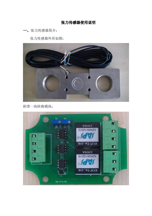
张力传感器使用说明一、张力传感器简介:张力传感器外形如图:附带一块转换模块:二、使用方法:1、将其串接在钢丝绳上。
2、需和远程控制箱配合使用,注意要将远程控制箱的18V 电源模块更换为12V 电源模块,同时把18V 继电器也换成12V 的继电器。
3、传感器的转换模块要放在远程控制箱内。
如图放置固定:固定处4、转换模块接线端子图:12V 正12V 负模拟量输出负模拟量输出正调整端口4-20mA 输出正4-20mA 输出负输出负(白)输出正(兰)电源正(黄)电源负(红)接线图:V-I/F 模块注意:张力传感器的配线不要进行延长,否则影响信号传输。
三、参数设置:1、#+A 进入参数设置。
2、设置张紧项,选择LAD ,只设置此项。
3、设置电机项,只设置电机输入点。
4、设置张力项,需设置的项目有张力→张力传感器输入点→量程/备压/起车张力值(此三项都要设置)→起车过程中最小张力值→起车最小张力值停车延时→运行过程中最小张力值→运行最小张力值停车延时→运行时张力调节值(增加值即上调张力,减小值即为下调张力,两项均设置)→皮带启动到运行的时间5、设置LAD项,只设置阀S1/S2/S3输出点。
LAD→阀S1/S2/S3输出点(三点都设置)6、设置LAD面板项,只设置其中的手动张力选择输入点,其余不设置。
LAD面板→手动张力选择输入点(两点都要设置)8、完毕后退出,显示以下界面注意:以上的参数必须设置,否则退不出参数。
设置时还要注意下面几项参数的关系,量程≧起车张力≧下调张力>上调张力≧运行最小张力≧起车最小张力≥备压张力。
张力传感器张力传感器(MC18/400/830/1898):MAGPOWR于1996年并入美塞斯,张力传感器,也叫张力检测器;张力传感器是张力控制过程中,用于测量卷材张力值大小的仪器。
张力传感器按其工作原理又可分为应变片型和微位移型。
应变片型是张力应变片和压缩应变片按照电桥方式连接在一起,当受到外压力时应变片的电阻值也随之改变,改变值的多少将正比于所受张力的大小;微位移型是通过外力施加负载,使板簧产生位移,然后通过差接变压器检测出张力,由于板簧的位移量极小,大约±200μm,所以称作微位移型张力检测器。
另外,由外型结构上又分为:轴台式、穿轴式、悬臂式等。
型号系列:称重检测器KOM-1系列 KOM-1-10KN KOM-1-20KN KOM-1-50KN KOM-1-100KN KOM-1-200KN称重检测器KOSD系列 KOSD-1000KN KOSD-2000KN称重检测器KOSD-40系列 KOSD-40-10KN KOSD-40-20KNKOSD-40-50KN KOSD-40-100KN KOSD-40-200KN锅炉张力计PST系列 PST-20KN PST-40KN PST-80KNPST-200KN钢丝绳张力检测器RTT系列 10~36mm纸带张力测量模块FMU系列纸带张力测量模块HTK系列纸带张力检测器KIP-1系列 KIP-1-10KN KIP-1-20KN双轴纸带张力检测器HTU系列 HTU-2Klb HTU-6KlbHTU-10Klb HTU-20Klb HTU-9KN HTU-27KN HTU-45KN HTU-89KN 检测器AST 31S系列DIN导轨检测器AST 3P系列DIN导轨张力传感器功能①小外形设计能最大限度的满足卷材的宽度②有着各种各样灵活多变的安装选择③坚固的连接带来长久的可靠性能④机械过载限制器保护过载机器⑤完整的惠斯通桥来确保测量精度⑥有英制和公制模式的国际通用设备张力传感器的安装螺钉安装,轴台安装,法兰安装张力传感器用途传感器的产品范围包括用于制药、化学、食品和其它需成批处理产业的高质量的测压元件、仪器和软件。
1、产品说明超薄式张力传感器,采用防尘防水防腐蚀设计,内置轴承,可配合隋轮辊安装或活轮辊安装。
具有输出信号线性好和响应快的特点。
外形小巧,特别适用于安装空间有限的场合。
由于内置温度补偿装置,所以无需额外的温度补偿。
该系列张力传感器普遍被应用于卷取控制设备和生产线上。
2、技术参数额定载荷:(N)250,500,750,1000,1500,30005000,6000,10000,20000,30000过载系数....................................1000%输入电压..................................12DC/AC张力信号输出...............................0-20mV应变片电阻值...........................350Ω/全桥综合误差.........................<±0.05%(超低)线性误差.................................<±0.5%重复性误差..............................<±0.02%环境湿度....................................95R.H.环境温度................................-30~+55℃温度漂移.................................0.004%/℃传感器接头规格................................WS20传感器材料..................................不锈钢3、产品特点☆输出信号稳定(无零点漂移)☆输出信号线性度好☆无需温度补偿网络☆可直接安装在设备立板或通过轴台座安装☆对高低张力具有同样的高灵敏性☆张力应变片与基体粘结强度高☆最大过载能力可达到1000%☆工业化防尘防水防腐蚀设计4、安装尺寸图5、安装尺寸表类型 A B C D E F G H I M。
IWPT SeriesIndustrial Wireless Pressure TransmitterWhilst every effort has been taken to ensure the accuracy of this document, we accept no responsibility for damage, injury, loss or expense resulting from errors or omissions, and reserve the right of amendment withoutnotice.This document may not be reproduced in any way without the prior writtenpermission of the company.Issue 2 September 2018Cynergy3 Components Ltd7 Cobham Road, Ferndown Ind Estate, WimborneDorset BH21 7PE, United KingdomTel:+44(0)1202897969,email:******************CONTENTS1. INTRODUCTION _______________________________________________________ 21.1 Safety Information____________________________________________________________ 21.2 Hardware Features ________________________________________________________ 22. UNPACKING __________________________________________________________ 23. PRODUCT IDENTIFICATION LABEL _____________________________________ 35. SETTING UP THE IWPT WIRELESS PRESSURE TRANSMITTER ___________ 46. TROUBLE-SHOOTING GUIDE __________________________________________ 57. SYSTEM PART NUMBERS______________________________________________ 68. SPECIFICATIONS______________________________________________________ 8 1. INTRODUCTION1.1 Safety InformationThis manual contains information that must be observed in the interest of your own safety and to avoid damage to assets. Please read this manual before installing and commissioning the device and keep the manual in an accessible location for all users.To satisfy FCC RF Exposure requirements for mobile and base station transmission devices, a separation distance of 20cm or more should be maintained between the antenna of this device and persons during operation. To ensure compliance operation at closer than this distance is not recommended. The antenna used for this transmitter must not be co-located or operating in conjunction with any other antenna or transmitter.1.2 Hardware FeaturesThe IWPT range of Wireless Pressure Transmitters has been designed to measure the Pressure of the medium connected and transmit the value to one of the IWR range of receivers where the value can be outputted as either a 4-20mA or 1-5Vdc signal.The IWR-1 has a single output and the IWR-5 has five outputs, each of which can be linked to an IWPT transmitter. The IWPT pressure transmitter works on the licence-free 2.4 GHz band.Ranges of up to 500m are possible using the standard transmitter and receiver unit with the optional 3dBi antenna giving a range of up to 750m. The transmitter is powered by a 3.6V lithium cell and care must be taken to insert the battery in the correct polarity.2. UNPACKINGThe instrument should be carefully inspected for signs of damage which may have occurred in transit. In the unlikely case that damage has been sustained, DO NOT use the instrument, but please retain all packaging for our inspection and contact your supplier immediately.3. PRODUCT IDENTIFICATION LABELThe unit delivered should be carefully inspected to ensure it is suitable for the application required. Detailed information on the product is included in the identification label and the user manual.Please ensure in particular, that the pressure range of the IWPT is suitable for the intended application and that the IWPT unit will not be subjected to pressures and/or temperatures greater than those specified in this manual.4. INSTALLING/CHANGING THE BATTERYA Lithium 3.6V battery is included inside the IWPT transmitter. The battery may be changed at any time but the correct polarity must be observed at all times! After the battery has been changed, the pushbutton SW1 should be pushed for 5s at the same time as the unit is switched on using SW3. This is to ensure the battery life count is set correctly when a new battery is installed.The internal LED will flash 5 times to indicate this procedure has been carried out successfully.The battery life is determined by the rate the transmitter sends the Pressure value to the receiver, this update rate can be selected using Dip Switch 1 and the default value is10s.Please dispose of all batteries as specified by the legislator according to the Closed Substance Cycle and Waste Management Act or country regulations.5.1 Mounting InstructionsEnsure that:-- The instrument is used on a pressure medium that is compatible with the wetted parts- The correct seal is used and that the maximum torque (see below) is not exceeded- Fluid is not allowed to freeze in the pressure port as the diaphragm may be ruptured- No sharp objects are inserted into the pressure port as the diaphragm may be damagedTighten the unit in place using a wrench on the 18mm A/F hexagon provided on the unit. Ensure that no more than 15Nm is applied, that the system is de-pressurised and that a suitable pressure seal is used.5.2 SETTING UP THE IWPT WIRELESS PRESSURE TRANSMITTER The IWPT instrument is shipped in a default configuration which allows the unit to connect with any default IWR receiver unit and transmit the measured pressure every 10s simply by switching the unit on using SW3 on the internal circuit board.If a different update rate is required, or a different network frequency channel is required these parameters can be selected using DIP Switch 1 as detailed below:Switches 1, 2, 3 & 4 select the RF Network the IWPT will transmit on. The default network for both the IWPT transmitter and IWR receiver is network 1.RF NETWORK 1 2 3 41 0 0 0 02 0 0 0 13 0 0 1 04 0 0 1 15 0 1 0 06 0 1 0 17 0 1 1 08 0 1 1 19 1 0 0 010 1 0 0 111 1 0 1 012 1 0 1 113 1 1 0 014 1 1 0 115 1 1 1 016 1 1 1 1Switches 5, 6 & 7 select the Transmission rate of the unit. This effectively sets how often the pressure value is sent to the receiver.Transmit time 5 6 710 seconds 0 0 020 seconds 0 0 130 seconds 0 1 060 seconds 0 1 1120 seconds 1 0 0600 seconds 1 0 11 second 1 1 05 seconds 1 1 1Switches 8, 9 and 10 set the Channel Number of the transmitter. This is used with the 5 channel receiver unit (IWR-5) to select which Pressure transmitter is linked to which4-20mA or 1-5Vdc output channel.Tx Channel Number 8 9 101 0 0 02 0 0 13 0 1 04 0 1 15 1 0 0The IWPT transmitter is now set up and ready to be used. Install the unit into the pipework as required and switch the unit ON using SW3. Pushbutton switch SW1 can be pushed to force the unit to transmit its current pressure and LED 1 will flash twice if the transmission has been received and acknowledged by an IWR receiver unit.If the unit has transmitted successfully the 4-20mA or 1-5Vdc output of the connected receiver unit will output a value reflecting the pressure level being measured.6. TROUBLE-SHOOTINGGUIDEProblem encountered Possible CausesLED1 doesn’t flash when pushbutton SW1 is pressed Unit not switched on, switch on using SW3. Battery not installed correctly.Battery needs replacing.LED1 only flashes once when SW1 is pressed IWR receiver not switched on.IWR receiver not set up for the same RF network.IWR receiver not within range of transmitter.If IWR-1 receiver is used, ensure that the transmitter is set to Tx Channel 1Output from IWR receiver isn’t equivalent to the Pressure being monitored IWR receiver set up incorrectly, see IWR user manual for further details.Check that the green external LED on the receiver is flashing when the transmitter pushbutton is pressed as receiver may be out of range.7. SYSTEM PART NUMBERSPart Number Pressure Range Receiver Output IWPT-G1000-00 0-1 Bar g 4-20mA or 1-5Vdc IWPT-G6000-00 0-6 Bar g 4-20mA or 1-5Vdc IWPT-GM1P9-00 -1-+9 Bar g 4-20mA or 1-5Vdc IWPT-G1002-00 0-10 Bar g 4-20mA or 1-5Vdc IWPT-G1602-00 0-16 Bar g 4-20mA or 1-5Vdc IWPT-CO184-00 -1-+24 Bar g 4-20mA or 1-5Vdc IWPT-G2502-00 0-25 Bar g 4-20mA or 1-5Vdc IWPT-G4002-00 0-40 Bar g 4-20mA or 1-5Vdc IWPT-G1003-00 0-100 Bar g 4-20mA or 1-5Vdc IWPT-G2503-00 0-250 Bar g 4-20mA or 1-5Vdc IWPT-G4003-00 0-400 Bar g 4-20mA or 1-5Vdc IWPTU-GP015-00 0-15psig 4-20mA or 1-5VdcIWPTU-GP030-00 0-30 psi g4-20mA or 1-5Vdc IWPTU-CO446-00 -14.5 to +150 psi g4-20mA or 1-5Vdc IWPTU-GP075-00 0-75 psi g4-20mA or 1-5Vdc IWPTU-GP100-00 0-100 psi g4-20mA or 1-5Vdc IWPTU-CO447-00 -14.5 to +350 psi g4-20mA or 1-5Vdc IWPTU-GP150-00 0-150 psi g4-20mA or 1-5Vdc IWPTU-GP300-00 0-300 psi g4-20mA or 1-5Vdc IWPTU-GP750-00 0-750 psi g4-20mA or 1-5Vdc IWPTU-GP1K5-00 0-1500 psi g4-20mA or 1-5Vdc IWPTU-GP3K6-00 0-3600 psi g4-20mA or 1-5Vdc IWPTU-GP5K8-00 0-5800 psi g4-20mA or 1-5Vdc IWPTL-G0050-00 0-50mbarg 4-20mA or 1-5VdcIWPTL-G0100-00 0-100mbarg 4-20mA or 1-5VdcIWPTL-G0250-00 0-250mbarg 4-20mA or 1-5VdcIWPTL-G0500-00 0-500mbarg 4-20mA or 1-5VdcIWPTL-G0750-00 0-750mbarg 4-20mA or 1-5VdcIWPTL-G1000-00 0-1000mbarg 4-20mA or 1-5VdcIWPTL-A0500-00 0-500mbarabs 4-20mA or 1-5Vdc IWPTL-A0750-00 0-750mbarabs 4-20mA or 1-5Vdc IWPTL-A1000-00 0-1000mbarabs 4-20mA or 1-5VdcPart Number Pressure Range Receiver Outputpsig 4-20mA or 1-5VdcIWPTLU-GP001-00 0-1g 4-20mA or 1-5VdcpsiIWPTLU-GP002-00 0-2g 4-20mA or 1-5VdcpsiIWPTLU-GP005-00 0-5psig 4-20mA or 1-5VdcIWPTLU-GP008-00 0-8g 4-20mA or 1-5VdcpsiIWPTLU-GP010-00 0-10g 4-20mA or 1-5VdcIWPTLU-GP015-00 0-15psipsiabs 4-20mA or 1-5VdcIWPTLU-AP005-00 0-5g 4-20mA or 1-5VdcpsiIWPTLU-AP010-00 0-10g 4-20mA or 1-5VdcIWPTLU-AP015-00 0-15psiPart Number Number of Output ChannelsIWR-1 OneIWR-5 FiveIANT-3 3 dBi AntennaIWPT-SA Swivel Adaptor (1/4” BSP)8. SPECIFICATIONSCynergy3 Components Ltd7 Cobham Road, Ferndown Ind Estate, WimborneDorset BH21 7PE, United KingdomTel:+44(0)1202897969,email:******************System PerformanceAccuracy (non-linearity & hysteresis <±0.25% / FS (BFSL) Setting Errors Zero & Full Scale,<±0.5% / FS Thermal Zero Shift <±0.04% / FS / °C Thermal Span Shift <±0.02% / °C typical Media Temperature -20 to +135 °C Ambient Temperature -20 to +50 °C Storage Temperature -20 to +80 °C Pressure Housing 303 Stainless Steel O Ring Seals VitonDiaphragm Ceramic Enclosure Material AcetalWeight 310g RF Transmitter Contains FCC W70MRF24J40MDME Power Requirements Lithium Ion C 3.6V Cell Battery Life 5 Years (10s transmission rate) Dimensions 132 x 79 x 52mm (L x W x D)Mounting Any Orientation。
张力传感器UPB()/SLM()/CLT()/TMT(轴台式圆饼式悬臂式圆筒式)上海宇泽机电设备有限公司SERVICE TEL 021.50923843:HTTP://WWW.ANYOUWEBT.1产品简介--------------------------------------“安优”品牌等四个系列张力传感器是在引进美国、德国和意大利同类张力传感器的技术上进行国产化改进的一款传感器,其量程范围大、过载能力强、线性度和重复度高、稳定性极好,采用了全密封整体结构使其响应频率大大提高,同时可防尘、防化学,各项关键参数均相当于欧美进口同类产品。
其中的应变片、温度补偿电路、防水防化防腐的胶水均采用德国原装进口。
“安优”品牌张力传感器由内至外的最优化工艺,确保用户长期稳定地使用,而无后顾之忧。
“安优”张力控制系统现已广泛应用于冶金、造纸、橡胶、胶卷、版、薄膜、涂布、造币、电源、印刷等各个行业。
UPB/SLM/CLT/TMT PS T.2基本工作原理------------------------------------“安优”品牌张力传感器采用应变片传感器原理,内置双悬臂梁,同时贴于悬臂梁上的四片应变片组成惠斯通全桥,当外部在悬臂梁上产生力矩时,此应变全桥失去平衡而输出差额电压,即传感器输出电压。
同时,为了保证传感器在一定温度波动范围内正确稳定地输出信号,其内置了一套温度补偿网络,从而使传感器输出的电压信号只与压力成线性正比。
组成惠斯通全桥的具体接线如下图.附:主要元件弹性体特种合金应变片德国(箔式)插座安装件(表面喷沙镀镍)--------------------HBM ----------WS16(WEIPU)----------T.3--------------------------------------主要规格3.1UPB(轴台式)张力传感器()............1:50......500%......10VDC/12VDC ......0-20mV ......120/......0.5%......0.02%......0.5%........-30~85......0.004%/......95R.H ......Ws16......2主要技术参数:最大工作压力UPB-M1UPB-M2张力范围过载系数输入电压信号输出应变片电阻Ω全桥线性误差<±重复度误差<±综合误差<±环境温度℃温度漂移℃环境湿度传感器接头本体材料特种合金12550/100/250/500(KG)0/2500/4000/(KG))6500/10000/16000(KG)(1)概述:UPB UPB 张力传感器采用了美国先进的传感器技术,全密封防腐蚀设计,单块式结构使得其响应频率大大提高,输出信号具有线性好和响应快的特点。