GE P1602压力传感器芯片产品说明书
- 格式:pdf
- 大小:203.92 KB
- 文档页数:2

®WIRINGUse 12 AWG wire maximum for electrical connections and 3/16˝ inner diameter rubber or plastic tubing for pneumatic connections. For your convenience we sell 3/16˝ I.D. rubber tubing, part number A-202, and 3/16˝ I.D. flexible vinyl tubing, part number A-220.See Figures 1 and 2 for wiring configurations and Figures 3 through 5for jumper designations.CAUTION•Ensure that the main supply pressure does not exceed 40 psi (276 kPa).•Ensure a minimum of 6 to 10 feet (1.8 to 3.0 m) of tubing between the transducer and the actuator.•For a 24 VAC supply voltage, ensure that the hot and neutral lines are not reversed. If more than one transducer is being powered from the same power supply, the hot and neutral lines should be the same for each transducer.* Do not connect 120 VAC to the electro-pneumatic transducer.Note:The transducer’s gage is for indication only. The transducer measures more precisely than what is displayed on the gage.WIRING DIAGRAMSFigures 1 and 2 illustrate typical wiring diagrams for the electro-pneumatic transducer.CAUTIONThis transducer contains a half-wave rectifier power supply and must not be powered from transformers powering other devices with non-isolated full-wave rectifier power supplies.ADJUSTMENTS - Jumper ConfigurationThe electro-pneumatic transducer is factory configured for a 4-20 mA input. To change the input, adjust the jumper settings as follows (see figures 3, 4 and 5.)©Copyright 2005Dwyer Instruments, Inc.Printed in U.S.A. 12/05FR# R1-443413-00TRANSDUCER OPERATION•Adjust the input signal to obtain a maximum output pressure for the appropriate range.•Ensure that the output is 15 or 20 psi (100 or 138 kPa).•Adjust the input signal to obtain a minimum output pressure.•Ensure that the output is 3 or 0 psi (20 or 0 kPa).CALIBRATIONAll electro-pneumatic transducers are factory calibrated to meet or exceed published specifications. If field adjustment is necessary, follow these instructions.1.Connect air to the Main port (see figure 6).2.Connect an accurate gage to the Branch port using a minimum of 6 to 10 feet (1.8 to3.0 m) of tubing.3.Connect the (+) and (–) terminals to an appropriate power source. The transducer can accept either a 24 VAC or VDC supply voltage. The maximum supply voltage should not exceed 30 VAC/VDC.4.Apply a low input signal to the (–) and (I) terminals (0 VDC or 4 mA).5.Adjust (Z) to obtain the desired low output pressure.6.Apply a high input signal to the (–) and (l) terminals (5/10 VDC or 20 mA).7.Adjust (S) to obtain the desired high output pressure.8.The zero and span controls are slightly interactive, so steps 4 through 7 should be repeated until the transducer is fully cali-brated.MANUAL OPERATION (select models)To manually control the transducer output, you will need to switch SW up for manual mode (see figure 6). Once in manual mode, you can increase or decrease the output by adjusting PB1 and PB2 (see figure 6).MAINTENANCEAfter final installation of the Series EPT-1 Electro-pneumatic Transducer, no routine maintenance is necessary. A periodic check of calibration is recommended following the procedure listed in the CALIBRATION section. Except for this, these transducers are not field serviceable and should be returned, freight prepaid, if repair is needed.Be sure to include a clear description of the problem plus any application information available. Contact customer service to receive a return goods authorization number before shipping.TRAN S DUCER 18-28 VAC TRAN S FORMER + HOT – NEUTRALCONTROLLER + OUTPUT– COMMON S HIELD/GROUNDLEGEND+ = S UPPLY VOLTAGE – = COMMON = INPUT+–TRAN S DUCER 18-28 VAC POWER S UPPLYCONTROLLER + OUTPUT– COMMON S HIELD/GROUNDLEGEND+ = S UPPLY VOLTAGE – = COMMON = INPUT+–+–MAINBRANCHZ S S W PB1PB2+========S UPPLY VOLTAGE COMMON INPUT ZERO S PANUP (MANUAL) DOWN (AUTO)INCREA S E DECREA S E+–Z S S W PB1PB2Figure 1: Wiring the electro-pneumatic transducer with a 24 VAC supply.Figure 2: Wiring the electro-pneumatic transducer with a 24 VDC supply.Figure 3: Jumper settings for electro-pneumatic transducers with 4-20mA input.Figure 4: Jumper settings for electro-pneumatic transducers with 0-5VDC input.Figure 5: Jumper settings for electro-pneumatic transducers with 0-10VDC input.Figure 6: Terminal locations on the electro-pneumatic transducer.。
nRF24L01+单片机2.4 GHz收发器产品说明书v1.0主要功能:全球通用的2.4 GHz ISM波段操作250kbps, 1Mbps and 2Mbps空中数据传输速率超低功率运行发射功率为0dBm(1.0mW)时,发射电流为11.3mA2Mbps空中数据传输速率,接收电流为13.5mA掉电电流为900nA待机-I电流26μA片内电压调整器1.9至3.6V电源供电范围增强型ShockBurst TM自动数据包处理自动包数据包事务处理6数据通道的MultiCeiver TM与nRF24L01嵌入式兼容空中数据速率250kbps 和1Mbps,与nRF2401A,nRF2402, nRF24E1和nRF24E2兼容低BOM成本±60ppm 16MHz晶振容许5V输入紧凑的20引脚4x4mm QFN封装应用无线 PC外围设备鼠标,键盘和遥控器三和一桌面捆绑先进的媒体中心遥控器网络电话耳机游戏控制器蓝牙模块运动手表和传感器消费电子产品射频遥控器家庭和商业自动化超低功率无线传感器网络RFID 射频识别资产跟踪系统玩具免责条款北欧半导体ASA有权做出随时更改,提高产品可靠性、功能或设计,不另行通知。
北欧半导体ASA不承担由于应用程序或使用任何所述产品或电路引起的责任。
所有应用程序的信息咨询,不构成说明书的组成部分。
极限值超过一个或多个限制的应力可能会造成设备永久性损坏。
这些应力等级只有在这样或那样的操作环境中提出,在规范中没有给出。
长时间暴露在限制值附近可能会影响设备的可靠性。
生命支持应用这些产品并非为因故障会引起人身伤害的维生装备,设备或系统设计的。
北欧半导体ASA客户使用或出售这些产品,他们将自担风险并同意完全赔偿北欧半导体ASA因使用不当或销售行为造成任何损害。
详细联系方式访问www.nordicsemi.no进入北欧半导体销售办事处和全世界的分销商网站总办公室:Otto Nielsens vei 127004 Trondheim电话: +47 72 89 89 00传真: +47 72 89 89 89www.nordicsemi.no写作惯例本产品规范遵循一套排版规则,文档一致,容易阅读。

ABP SERIESFor Use in Medical VentilatorsBasic Board Mount Pressure SensorsHigh Accuracy, Compensated/Amplified60 mbar to 1.6 bar | 1 psi to 15 psiDigital or Analog Output, Liquid Media CapableDESCRIPTIONThe ABP Series are piezoresistive siliconpressure sensors offering a ratiometricanalog or digital output for readingpressure over the specified full scalepressure span and temperature range.They are calibrated and temperaturecompensated for sensor offset,sensitivity, temperature effects andaccuracy errors (which include non-linearity, repeatability and hysteresis)using an on-board Application Specific Integrated Circuit (ASIC). Calibrated output values for pressure are updated at approximately 1 kHz for analog and2 kHz for digital. All products are designed and manufactured according to ISO 9001 standards.• Dry gases option: The input port is limited to non-corrosive, non-ionic media (e.g., dry air, gases) and should not be exposed to condensation. The gases are limited to media compatible with high temperature polyamide, silicone, alumina ceramic, silicon, gold, and glass.• Liquid media option: Includes an additional silicone-based gel coating to protect the electronics underport P1, which enables use withnon-corrosive liquids (e.g. water and saline) and in applications where condensation can occur. Since port P2 is designed for use with non-corrosive liquids, this option is often suitable for wet-wet differential sensing. DIFFERENTIATION• Enhanced accuracy helps the design engineer fully understand the error in measurement.• Wide supply voltage range offers design flexibility.• Power consumption when utilizing sleep mode option allows for use in battery-powered applications.FEATURES• Measures gage and differentialpressures• Total Error Band (see Figure 1): ±1.5 %FSS• Liquid media option: Allows for wet/wet operation on dual ported devices• Industry-leading long-term stability:±0.25 %FSS• Industry-leading accuracy: ±0.25%FSS BFSL• Wide pressure range: 60 mbar to 1.6 bar |1 psi to 15 psi• As small as 8 mm x 7 mm• High burst pressures (see Table 7)• Calibrated over temperature range of0°C to 50°C [32°F to 122°F]• Operates from a single power supply ofeither 3.3 Vdc or 5.0 Vdc• Output: Ratiometric analog or I2C- orSPI-compatible 12-bit digital• Power consumption: 2 uA typical whenutilizing sleep mode option• Meet IPC/JEDEC J-STD-020D.1 MoistureSensitivity Level 1 requirements• REACH and RoHS compliant• Options: Internal diagnostic function,liquid media, sleep mode, temperatureoutput32350389Issue AVALUE TO CUSTOMERS• Simplifies design-in: Small sizesaves room on the PC board (PCB),or simplifies design in smaller andlower power devices. Meets MoistureSensitivity Level 1 requirements, whichallows for unlimited shelf life whenstored at <30 ºC/85 %RH and, undermost storage conditions, allows forPCB soldering without any materialconcern about solder joint quality dueto aging of the sensor terminals, whichminimizes the concern about agingof the terminals prior PCB assembly.Pressure choices allow engineersto select range required for theirapplication. Leadless SMT, SMT, andDIP package options.• Cost-effective: Small size helpsengineers reduce design andmanufacturing costs while maintainingenhanced performance and reliabilityof the systems they design.• Accurate: Total Error Band (TEB) andwide pressure range enable engineersto optimize system performance byimproving resolution and systemaccuracy. Optional internal diagnosticsvalidate that the sensor readings arecorrect.• Flexible: Supply voltage range, varietyof pressure units, types, and ranges,output options, and wide operatingtemperature range simplify use in theapplication.• Versatile: Wet-media compatibility,sleep mode, and temperatureoutput options make the sensor aversatile choice for Internet of Thingsapplications.• Honeywell Brand: Utilizes proprietaryHoneywell technology, and is protectedby multiple global patents.POTENTIAL MEDICALAPPLICATIONSOxygen concentrators, patientmonitoring, sleep apnea equipment,ventilators/portable ventilators.PORTFOLIOHoneywell offers a varietyof board mount pressuresensors for potential use inmedical and industrial applications.To view the entire product portfolio,click here.FIGURE 1. TOTAL ERROR BANDTotal Error Band (TEB) is a single specification that includes allpossible sources of error. TEB should not be confused with accuracy, which is actually a component of TEB. TEB is the worst error that the sensor could experience. The TEB specification on a datasheet may be confusing. Honeywell uses the TEB specification in its datasheet because it is the most comprehensive measurement of a sensor’s true accuracy. Honeywell also provides the accuracy specification in order to provide a common comparison with competitors’ literature that does not use the TEB specification. Many competitors do not use TEB—they simply specify the accuracy of their device. Theiraccuracy specification, however, may exclude certain parameters. On their datasheet, the errors are listed individually. When combined, the total error (or what would be TEB) can be significant.All Possible Errors2Ratiometricity of the sensor (the ability of the device output to scale to the supply voltage) is achieved within the specified operating voltage.3The sensor is not reverse polarity protected. Incorrect application of supply voltage or ground to the wrong pin may cause electrical failure. 4Operating temperature range: The temperature range over which the sensor will produce an output proportional to pressure.5Compensated temperature range: The temperature range over which the sensor will produce an output proportional to pressure within the specified performance limits.6Temperature output option: Typical temperature output error over the compensated temperature range of 0°C to 50°C. Operation in Sleep Mode may affect temperature output error depending on duty cycle. 7Total Error Band: The maximum deviation from the ideal transfer function over the entire compensated temperature and pressure range. Includes all errors due to offset, full scale span, pressure non-linearity, pressure hysteresis, repeatability, thermal effect on offset, thermal effect on span, and thermal hysteresis.8Full Scale Span (FSS): The algebraic difference between the output signal measured at the maximum (Pmax.) and minimum (Pmin.) limits of the pressure range. (See Figure 2.)9Accuracy: The maximum deviation in output from a Best Fit Straight Line (BFSL) fitted to the output measured over the pressure range at25°C [77°F]. Includes all errors due to pressure non-linearity, pressure hysteresis, and non-repeatability.FIGURE 2. TRANSFER FUNCTION LIMITS 1Analog VersionsDigital Versions1Transfer Function “A” is shown. See Figure 3 for other available transfer functions.0102030405060708090100123456789101.5% Total Error BandP min.P max.Pressure (example unit)O u t p u t (%V s u p p l y )0.8 x Vsupply P max. – P min.Output (V) =x (Pressure applied – P min.) + 0.10 x VsupplyIdeal80%P max. – P min.Output (% of 214 counts) =x (Pressure applied – P min.) + 10%O u t p u t (% o f214 c o u n t s )010203040506070809010012345678910Pressure (example unit)P min.P max.1.5% Total Error BandIdealFIGURE 3. NOMENCLATURE AND ORDER GUIDEFor example, ABPDNNN150PGAA3 defines an ABP Series Amplified Basic Pressure Sensor, DIP package, NN pressure port, dry gases only, no diagnostics, 150 psi gage pressure range, analog output type, 10% to 90% of Vsupply (analog), transfer function,no temperature output, no sleep mode, 3.3 Vdc supply voltage.1 Custom pressure ranges are available. Contact Honeywell Customer Service for more information.2See the explanation of sensor pressure types in Table 4. 3The transfer function limits define the output of the sensor at a given pressure input. By specifying Pmin. and Pmax., the output at Pmin. and Pmax., the complete transfer function of the sensor is defined. See the graphical representations of the transfer function in Figure 3.to the operating pressure range. Exposure to higher pressures may cause permanent damage to the product. Unless otherwise specified this applies to all available pressure ports at any temperature with the operating temperature range.2Burst pressure: The maximum pressure that may be applied to the specified port (P1 or P2) of the product without causing escape of pressure media. Product should not be expected to function after exposure to any pressure beyond the burst pressure.3Common mode pressure: The maximum pressure that can be applied simultaneously to both ports of a differential pressure sensor without causing changes in specified performance.V SUPPLYV SUPPLY V OUT *Ground*Analog output version only.0.1 uF0.001 uF*FIGURE 4. RECOMMENDED FILTER CAPFIGURE 5. DIP PACKAGE DIMENSIONAL DRAWINGS (FOR REFERENCE ONLY: MM [IN].)DIP NN: No portDIP AN:Single axial barbed portFIGURE 5. DIP PACKAGE DIMENSIONAL DRAWINGS (CONTINUED)DIP RN: Single radial barbed portDIP RR: Dual radial barbed ports, same sideFIGURE 6. SMT PACKAGE DIMENSIONAL DRAWINGS (FOR REFERENCE ONLY: MM [IN].)SMT NN: No portSMT AN: Single axial barbed portSMT RN: Single radial barbed portSMT RR: Dual radialbarbed ports, both sides4,0FIGURE 7. LEADLESS SMT PACKAGE DIMENSIONAL DRAWINGS (FOR REFERENCE ONLY: MM [IN].)Leadless SMT NN: No portLeadless SMT AN: Singleaxial barbed port32350389-A-EN | A | 04/20© 2020 Honeywell International Inc. All rights reserved.WARRANTY/REMEDYHoneywell warrants goods of its manu-facture as being free of defective materi-als and faulty workmanship during the applicable warranty period. Honeywell’s standard product warranty applies un-less agreed to otherwise by Honeywell in writing; please refer to your order ac-knowledgment or consult your local sales office for specific warranty details. If war-ranted goods are returned to Honeywell during the period of coverage, Honeywell will repair or replace, at its option, without charge those items that Honeywell, in its sole discretion, finds defective. The foregoing is buyer’s sole remedy and is in lieu of all other warranties, expressed or implied, including those of merchantability and fitness for a particular purpose. In no event shall Honeywell be liable for consequential, special, or indirect damages.While Honeywell may provide applica-tion assistance personally, through our literature and the Honeywell web site, it is buyer’s sole responsibility to determine the suitability of the product in the ap-plication.Specifications may change without notice. The information we supply isbelieved to be accurate and reliable as of this writing. However, Honeywell assumes no responsibility for its use.m WARNINGPERSONAL INJURYDO NOT USE these products as safety or emergency stop devices or in any other application where failure of the product could result in personal injury.Failure to comply with theseinstructions could result in death or serious injury.m WARNINGMISUSE OFDOCUMENTATION•The information presented in this product sheet is for reference only. Do not use this document as a product installation guide.•Complete installation, operation, and maintenance information is provided in the instructions supplied with each product.Failure to comply with theseinstructions could result in death or serious injury.ADDITIONAL MATERIALSThe following associated literature is available at :• Product range guide • Installation instructions • Application noteFOR MORE INFORMATIONHoneywell Sensing and Internet ofThings services its customers through a worldwide network of sales offices and distributors. For application assistance, current specifications, pricing or the nearest Authorized Distributor, visit or call:USA/Canada +1 302 613 4491Latin America +1 305 805 8188Europe +44 1344 238258Japan +81 (0) 3-6730-7152Singapore +65 6355 2828Greater China+86 4006396841HoneywellSensing and Internet of Things 830 East Arapaho Road Richardson, TX 75081 。
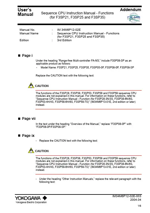
Addendum Manual No. : IM 34M6P12-02EManual Name : Sequence CPU Instruction Manual - Functions(for F3SP21, F3SP25 and F3SP35)Edition :3rdEditionPage iUnder the heading “Range-free Multi-controller FA-M3,” include F3SP08-SP as anapplicable product as follows:- Model Name: F3SP21, F3SP25, F3SP35, F3SP05-0P, F3SP08-0P, F3SP08-SPReplace the CAUTION text with the following text:CAUTIONThe functions of the F3SP28, F3SP38, F3SP53, F3SP58 and F3SP59 sequence CPUmodules are not explained in this manual. For information on these functions, refer to“Sequence CPU Instruction Manual - Function (for F3SP28-3N/3S, F3SP38-6N/6S,F3SP53-4H/4S, F3SP58-6H/6S, F3SP59-7S)” (IM34M6P13-01E, 2nd edition or later)instead.Page viiIn the text under the heading “Overview of the Manual,” replace “F3SP08-0P” with“F3SP08-0P/F3SP08-SP.”Page ix-Replace the CAUTION text with the following text:CAUTIONThe functions of the F3SP28, F3SP38, F3SP53, F3SP58 and F3SP59 sequence CPUmodules are not explained in this manual. For information on these functions, refer to“Sequence CPU Instruction Manual - Function (for F3SP28-3N/3S, F3SP38-6N/6S,F3SP53-4H/4S, F3SP58-6H/6S, F3SP59-7S)” (IM34M6P13-01E, 2nd edition or later)instead.- Under the heading “Other Instruction Manuals,” replace the relevant paragraph with the following text:User’sManual Sequence CPU Instruction Manual - Functions(for F3SP21, F3SP25 and F3SP35)z When creating programs using ladder language, refer to:- FA-M3 Programming Tool WideField2 (IM34M6Q15-01E)or- FA-M3 Programming Tool WideField (IM34M6Q14-01E); and- FA-M3 Programming Tool WideField – Application (IM34M6Q14-02E)or- Ladder Diagram Support Program M3 (IM 34M6Q13-01E)Page xUnder the title “Other Instruction Manuals,” replace the relevant paragraph with thefollowing text:z For information on the functions of F3SP28, F3SP38, F3SP53, F3SP58 and F3SP59 sequence CPU modules, refer to:- Sequence CPU Instruction Manual – Function (for F3SP28-3N/3S, F3SP38-6N/6S, F3SP53-4H/4S, F3SP58-6H/6S, F3SP59-7S) (IM34M6P13-01E, 2nd editionor later)Page A1-5, Table A1.2, “Device List”In the “Device” column,remove “1-ms timer,” and replace “100-µs timer” with “1-ms timer.”Page A1-5, Table A1.2, “Device List”In the “Quantity” column for F3SP25, correct values as follows:- For the number of link registersWrong: 2048Correct: 8192- For the number of extended shared registersWrong: 0Correct: 3072Page A1-7Replace the footnote under “Configuration Function” with the following text:* FA-M3 Programming Tool WideField2, FA-M3 Programming Tool WideField, or Ladder Diagram Support Program M3.Page A1-9, Table A1.3, “Configuration Ranges (3 of 4)”In the Item column, replace the condition for momentary power failure detection modewith the following text:Effective if power supply modules other than F3PU01-0N are used.Page A2-5, Section A2.4, “Programming Tools"- Replace the text with the following text:The FA-M3 programming tool WideField2 (abbreviated hereinafter as WideField2), FA-M3programming tool WideField, and Ladder Diagram Support Program M3 are programmingtools available for the FA-M3 system.- Replace the table in Section A2.4.1 with the following table:Description Software Model Supported CPUsFA-M3 Programming ToolWideField2 SF620-ECWF3SP05 F3SP28F3SP08 F3SP38F3SP21 F3SP53F3SP25 F3SP58F3SP35 F3SP59F3FP36Pages A3-3, B1-1, and C1-1In the text, replace "F3PU10-0N" with "F3PU10-0N/F3PU10-0S",and replace "F3PU20-0N" with "F3PU20-0N/F3PU20-0S."Pages A3-10, A6-25, A6-28, A6-31, A6-36, and A6-56In the text, replace “WideField” with “WideField2,” andchange the name of the manual to “FA-M3 Programming Tool WideField2(IM34M6Q15-01E).”Pages A4-10 and A4-33In the text, replace “F3SP58” with “F3SP58 and F3SP59.”Page A6-36Add the following CAUTION text:CAUTIONThe transmission rate and data format does not apply to downloading of program not viathe programming port, e.g. through the Ethernet interface module. If the transmission rateor data format is changed, the sequence CPU module must be switched off and switchedon again before the change will be reflected.Page A6-42, “(2) Response Format and Elements”In the table under “When Communication is Abnormal”, correct the number of bytes forcommand as follows:Wrong: 2Correct: 3Page B2-4- Replace the text under Section B2.3, “Programming Tools,” with the following text:The FA-M3 programming tool WideField2 (abbreviated hereinafter as WideField2), FA-M3programming tool WideField, and Ladder Diagram Support Program M3 are programmingtools available for the F3SP05-0P sequence CPU module.- Replace the table in Section B2.3.1 with the following table:Description Software Model Supported CPUsFA-M3 Programming Tool WideField2 SF620-ECWF3SP05 F3SP28F3SP08 F3SP38F3SP21 F3SP53F3SP25 F3SP58F3SP35 F3SP59F3FP36Pages Toc-6 and Toc-C1Replace the title of PART C with the following text:PART C for CPU module designed for the FA-M3 Value II system (F3SP08-0P andF3SP08-SP)Page C1-1- Add F3SC23- to F3SC22- as applicable FA-M3 Value II system controllers.- Replace “F3SP08-0P” with “F3SP08- P.”- Append the following text under “Overview”:F3SP08-0P and F3SP08-SP have exactly the same dimensions, internal circuitry andother characteristics, except that F3SP08-0P has M3.5-screw terminals butF3SP08-SP has M4-screw terminals.-Replace the CAUTION text under “Overview” with the following text:CAUTIONFA-M3 Programming Tool WideField R2.04 or later or FA-M3 Programming Tool WideField2 is required when using the F3SP08- P sequence CPU module.Page C1-9, Section C1.2.5, “External Dimensions”Replace the diagram with the following diagram.F3SP08-0P/F3SP08-SP Unit mmPage C1-10, Section C1.3.1, “Units”Replace the entire text under “Main Unit” with the following text:Main UnitFor the FA-M3 Value II system, the F3SC22- /F3SC23- is called a main unit andconsists of the following modules:module- F3BU04-0N Base- F3SP08-0P Sequence CPU module with power supply (M3.5 screws) andmemory- F3SP08-SP Sequence CPU module with power supply (M4 screws) and memorymodule- F3WD32-3F I/Omodule- F3WD64-3F I/Omodule- F3XD16-3F Inputmodule- F3YD14-5A OutputInstall the F3SP08- P sequence CPU module in the leftmost slot of the F3BU04-0N base module and the other I/O modules in slot 2 (or slots 2 and 3). In the remaining third and fourth slots (or only slot 4), install other necessary I/O modules or special modules.001 002 003 004001 002 003 004Main Unit F3SC22-1FF 3S P 08-0PF 3W D 32-3FI /O M o d u l eI /O M o d u l eMain Unit F3SC23-1FF 3S P 08-S PF 3W D 32-3FI /O M o d u l e I /O M o d u l e001 002 003 004001 002 003 004Main Unit F3SC22-2FF 3S P 08-0PF 3W D 64-3FI /O M o d u l eI /O M o d u l eMain Unit F3SC23-2FF 3S P 08-S PF 3W D 64-3FI /O M o d u l e I /O M o d u l e001 002 003 004001 002 003 004 Main Unit F3SC22-1AF 3S P 08-0PF 3X D 16-3FF 3Y D 14-5AI /O M o d u l eMain Unit F3SC23-1AF 3S P 08-S PF 3X D 16-3FF 3Y D 14-5AI /O M o d u l ePage C2-4, Section C2.3, “Programming Tools"- Replace the body text with the following text:The FA-M3 programming tool WideField2 (abbreviated hereinafter as WideField2) and FA-M3 programming tool WideField are programming tools available for the F3SP08-0P sequence CPU module.- Replace the table in Section C2.3.1 with the following table:Description Software ModelSupported CPUs FA-M3 Programming ToolWideField2SF620-ECWF3SP05 F3SP28 F3SP08 F3SP38 F3SP21 F3SP53 F3SP25 F3SP58 F3SP35 F3SP59 F3FP36- Replace the CAUTION text with the following:CAUTIONFA-M3 Programming Tool WideField2 or FA-M3 Programming Tool WideField R2.04 or later version is required when using the F3SP08- P sequence CPU module.。
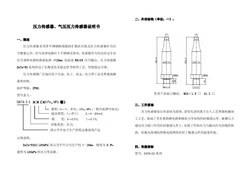
压力传感器、气压压力传感器说明书一、概述压力传感器采用带不锈钢隔离膜的扩散硅压阻式压力传感器作为信号测量元件,信号处理电路位于不锈钢壳体内,传感器信号经过经过专业信号调理电路转换成标准4-20mA 电流或RS485信号输出。
压力传感器DATA-52系列经过了长期老化及稳定性考核等工艺,性能稳定可靠。
压力传感器广泛地应用于石油、化工、冶金、电力等工业过程现场测量和控制。
防护等级:IP68。
型号意义:示例说明:DATA-5202(100kPa)表示为平升公司生产的4~20mA ,精度为0.5%,量程为100kPa 的压力变送器。
二、外形结构(单位:mm ):供货产品接口螺纹: M20×1.5 □ G1/2 □三、工作原理压力传感器是以单晶硅为基体,采用先进的离子注入工艺和微机械加工工艺,制成了具有惠斯顿电桥和精密力学结构的硅敏感元件。
被测压力通过压力接口作用在硅敏感元件上,实现了所加压力与输出信号的线性转换,经激光修调的厚膜电阻网络补偿了敏感元件的温度性能。
四、性能指标 型号:DATA-52系列通讯类型:1—串口; 2—4~20mA;精 度:0—0.5%; 1—0.1%;DATA-5 2 ××(×kPa 、MPa 等)量程:0—×,单位:kPa 、MPa (一般在标牌中标注) 采集类型:压力;唐山平升电子生产的变送器系列产品测量介质:液体或气体(对不锈钢壳体无腐蚀)量程:0-10MPa输出信号:4-20mA;RS485供电电源:12/24V DC精度等级:0.1%FS;0.5%FS环境温度:-10℃~80℃存储温度:-40℃~85℃过载能力:150%FS稳定性能:±0.05%FS/年; ±0.1%FS/年零点温度系数:±0.01%FS/℃满度温度系数:±0.02%FS/℃防护等级:IP68结构材料:外壳:不锈钢1Cr18Ni9Ti 密封圈:氟橡胶传感器外壳:不锈钢1Cr18Ni9Ti 膜片:不锈钢316L电缆:φ7.2mm聚氨酯专用电缆(配套2米,超出部分按长度加价)五、注意事项1.当收到压力传感器时请检查包装是否完好,并核对变送器型号与规格是否与您选购的产品相符。
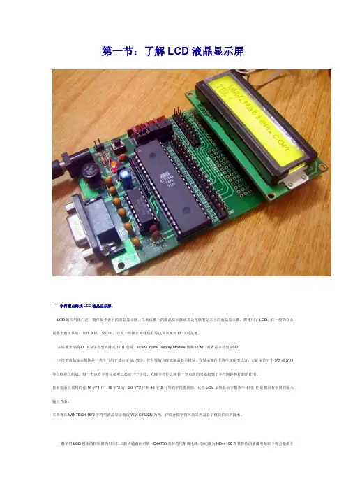
第一节:了解LCD液晶显示屏一:字符型点阵式LCD液晶显示屏:LCD的应用很广泛,简单如手表上的液晶显示屏,仪表仪器上的液晶显示器或者是电脑笔记本上的液晶显示器,都使用了LCD。
在一般的办公设备上也很常见,如传真机,复印机,以及一些娱乐器材玩具等也常常见到LCD的足迹。
本站要介绍的LCD为字符型点阵式LCD模块(liquid Crystal Display Module)简称LCM,或者是字符型LCD。
字符型液晶显示模块是一类专门用于显示字母,数字,符号等的点阵式液晶显示模块。
在显示器件上的电极图型设计,它是由若干个5*7或5*11等点阵符位组成。
每一个点阵字符位都可以显示一个字符。
点阵字符位之间有一空点距的间隔起到了字符间距和行距的作用。
目前市面上常用的有16字*1行,16字*2行,20字*2行和40字*2行等的字符模块组。
这些LCM虽然显示字数各不相同,但是都具有相同的输入输出界面。
本章将以WINTECH 16*2字符型液晶显示模块WM-C1602N为例,详细介绍字符兴高采烈晶显示模块的应用技术。
一般字符LCD模块的控制器为日本日立新华通讯社司的HD44780及其替代集成电路,驱动器为HD44100及其替代的集成电路以下将会略做介绍。
一般初学者由字符型LCD入手比较简单,学完之后,再进一步控制图案型LCD模块。
图1.1所示为16*2地的外观,表1.2为LCM的接脚及功能。
看她的样子在太酷爱,现在我拿她作为讲解实例。
字串8图1.1a:液晶显示模块WM-C1602N背后图1.1b: 液晶显示模块WM-C1602N丰姿图1.1c:液晶显示模块WM-C1602N规格字串4表1.2:液晶显示模块WM-C1602N的接脚及功能应用液晶显示模块WM-C1602N那得先对她的内部结构有所了解,下一节我将会带大家进一步的了解液晶显示模块WM-C1602N。
第二节:LCD液晶显示屏的内部结构液晶显示模块WM-C1602N的内部结构可以分成三部份:一为LCD控制器,二为LCD驱动器,三为LCD显示装置,如图示2.1所示:字串1图2.1:LCM内部方块图字串1目前大多数的LCD液晶显示器的控制器都有采用一颗型号为HD44780的集成电路作控制器。

NPA-500B-015AGEMeasurement & Control Solutions Advanced SensorsPressure Sensor Type NPAApplication Guide910-289 Rev. BAugust 2010Contents Pressure Sensor Type NPA1.Typical Application Circuits. . . . . . . . . . . . . . . . . . . . . . . . . . . . . . . . . . . . . . . . . . . . . . . . . . . .11.1General Description . . . . . . . . . . . . . . . . . . . . . . . . . . . . . . . . . . . . . . . . . . . . . . . . . . . .11.2Block Diagram . . . . . . . . . . . . . . . . . . . . . . . . . . . . . . . . . . . . . . . . . . . . . . . . . . . . . . . .11.3Analog Circuits. . . . . . . . . . . . . . . . . . . . . . . . . . . . . . . . . . . . . . . . . . . . . . . . . . . . . . . .21.4Digital Circuits . . . . . . . . . . . . . . . . . . . . . . . . . . . . . . . . . . . . . . . . . . . . . . . . . . . . . . . .31.5Output Impedance . . . . . . . . . . . . . . . . . . . . . . . . . . . . . . . . . . . . . . . . . . . . . . . . . . . . .31.6Output Short Protection . . . . . . . . . . . . . . . . . . . . . . . . . . . . . . . . . . . . . . . . . . . . . . . . .32.Pin Connections . . . . . . . . . . . . . . . . . . . . . . . . . . . . . . . . . . . . . . . . . . . . . . . . . . . . . . . . . . . .43.Digital Output . . . . . . . . . . . . . . . . . . . . . . . . . . . . . . . . . . . . . . . . . . . . . . . . . . . . . . . . . . . . . .53.1General. . . . . . . . . . . . . . . . . . . . . . . . . . . . . . . . . . . . . . . . . . . . . . . . . . . . . . . . . . . . . .53.2Bit Encoding. . . . . . . . . . . . . . . . . . . . . . . . . . . . . . . . . . . . . . . . . . . . . . . . . . . . . . . . . .53.3Mode 1 - Pressure Only. . . . . . . . . . . . . . . . . . . . . . . . . . . . . . . . . . . . . . . . . . . . . . . . .73.4Mode 2 - Pressure With Temperature . . . . . . . . . . . . . . . . . . . . . . . . . . . . . . . . . . . . . .83.5Data Transmission . . . . . . . . . . . . . . . . . . . . . . . . . . . . . . . . . . . . . . . . . . . . . . . . . . . . .93.6How to Read a Data Packet. . . . . . . . . . . . . . . . . . . . . . . . . . . . . . . . . . . . . . . . . . . . . .93.7How to Read a Data Packet Using a Microcontroller. . . . . . . . . . . . . . . . . . . . . . . . . . .93.8PIC1 Assembly Code Example . . . . . . . . . . . . . . . . . . . . . . . . . . . . . . . . . . . . . . . . . .103.98051 C++ Code Example. . . . . . . . . . . . . . . . . . . . . . . . . . . . . . . . . . . . . . . . . . . . . . .134.Package Dimensions . . . . . . . . . . . . . . . . . . . . . . . . . . . . . . . . . . . . . . . . . . . . . . . . . . . . . . .164.1Manifold Fitting. . . . . . . . . . . . . . . . . . . . . . . . . . . . . . . . . . . . . . . . . . . . . . . . . . . . . . .164.2Barbed Fitting. . . . . . . . . . . . . . . . . . . . . . . . . . . . . . . . . . . . . . . . . . . . . . . . . . . . . . . .174.3No Port. . . . . . . . . . . . . . . . . . . . . . . . . . . . . . . . . . . . . . . . . . . . . . . . . . . . . . . . . . . . .195.Suggested PCB Pad Layout. . . . . . . . . . . . . . . . . . . . . . . . . . . . . . . . . . . . . . . . . . . . . . . . . .206.Soldering. . . . . . . . . . . . . . . . . . . . . . . . . . . . . . . . . . . . . . . . . . . . . . . . . . . . . . . . . . . . . . . . .206.1Standard Reflow Soldering. . . . . . . . . . . . . . . . . . . . . . . . . . . . . . . . . . . . . . . . . . . . . .206.2Manual Soldering. . . . . . . . . . . . . . . . . . . . . . . . . . . . . . . . . . . . . . . . . . . . . . . . . . . . .20 ii Application GuidePressure Sensor Type NPA1.Typical Application Circuits1.1General DescriptionThe NPA series of pressure sensors combines GE's SenStable® silicon fusion bonded pressure die technology with packaged electronics to provide highly stable, amplified and calibrated pressure measurement in a cost effective surface mount package.The NPA is offered in a range of pressure ratings. Various port configurations are available to measure absolute, gauge and differential pressures. Versions are offered with either analogue or digital outputs.This application guide should be read in conjunction with product data sheet 920-477.1.2Block DiagramApplication Guide1Pressure Sensor Type NPA1.3Analog CircuitsNote:Standard analogue versions of NPA are configured for ratiometric operation as shown in Figure2. For the circuits in Figures 3 and 4, a special version of the NPA with pin 10 (Vgate) activated should be used.Typical output load resistor R L (to V supply or Ground) = 10 kΩ (minimum 2.5 kΩ)Typical output load capacitance C L = 10 nF (maximum 15 nF)2Application GuidePressure Sensor Type NPA1.4Digital CircuitsThe circuits in Figures 2,3 & 4 on Page 2 can also be used for digital outputs with the following conditions:•The load resistor or capacitance is not required•No pull-down resistor is allowed•If a line resistor or pull-up resistor is used, the requirement for rise time (≤5 μs) must be met1.5Output ImpedanceThe source impedance defined by voltage drop due to load current is not specified as such for the NPA. The sensor incorporates a unity gain buffer at the output to control the output voltage within a range of load current / resistances. An error compensation circuit tracks and reduces the amplifier offset voltage to <1 mV.1.6Output Short ProtectionThe NPA does not incorporate short protection. A resistor R SP, as specified in Table1 below, should therefore be connected in series with the output.Table 1: Short Protection ResistorAmbient Temp. (°C)Resistor R SP (ohm)Up to 8551Up to 125100To minimize the effect on measurement accuracy caused by this resistance in analog mode, the load impedance R L should be chosen to ensure that R L>>R SP.Application Guide3Pressure Sensor Type NPA2.Pin ConnectionsTable 2: Pin ConnectionsPin No.Pin Name Pin Function1NC Not connected2NC Not connected3VP Sensor interface positive output4VSSP Sensor interface ground5NC Not connected6VSS Ground supply7NC Not connected8SIG Analog out, Digital out9VDD Supply voltage10Vgate Gate control for external JFET regulation/overvoltage protection11VN Sensor interface negative output12VDDP Sensor interface positive excitation13NC Not connected14NC Not connected4Application GuideApplication Guide 5Pressure Sensor Type NPA3.Digital Output3.1GeneralThe NPA sensor is available in 2 versions with digital output interface:•Pressure data only: NPA-600 series•Pressure & temperature data: NPA-601 seriesThe bit encoding is similar to Manchester in that clocking information is embedded into the signal (falling edges of the signal occur at regular periods). This allows the protocol to be largely insensitive to baud rate differences between the two ICs communicating. In user applications, the NPA sensor will be transmitting information and another IC in the system (typically a microcontroller) will read the data.3.2Bit EncodingData bits are transmitted as a Manchester duty-cycle encoded signal:Start bit 50% duty cycle used to set up strobe time Logic 175% duty cycle Logic 025% duty cycleStop BitHigh signal for half a bit widthThere is a half stop bit time between bytes in a packet.Figure 5: Manchester Duty CycleBit Window31.25 μs @ 32 kHz baud ratePressure Sensor Type NPA6Application Guide3.2 Bit Encoding (cont.)An oscilloscope trace of the data transmission demonstrates the bit encoding. Figure 6 below shows a single packet of value 96 hex (= 10010110 bin = 150 dec) being transmitted. Because 96Hex is already even parity, the parity bit P is set to 0.1 0 1 0 1 1 0 PSPressure Sensor Type NPA3.3Mode 1 - Pressure OnlyThe sensor first transmits the high byte of pressure data, followed by the low byte. The data resolution is 14-bits, so the upper two bits of the high byte are always zero padded. There is a half stop bit time between bytes in a packet. That means that, for the time of half a bit width, the signal level is high. Combining the high and low data bytes provides a 14-bit number corresponding to the pressure reading (see Figure7 below).Figure 7: Digital Output Bridge ReadingsThe actual pressure reading is dependent on the calibration set points for zero and full-scale pressure. This is illustrated in the following example, for a sensor that has been calibrated with the following parameters:•Excitation: 5 V olts•Full-scale Pressure: 10” H2O•Full-scale Pressure: set to 90% of rail•Zero Pressure: set to 10% of rail.In this example, the sensor would deliver the analog/digital outputs shown in Table4 below.Table 3: Analog/Digital Outputs for ExamplePressure (in. H2O)Analog V% of Rail Voltage Digital Value*-1.250.00000.51016385 2.550819210 4.5901474511.25 5.010016383*this is the 14-bit number referenced in Figure7 above, in decimal formatApplication Guide73.4Mode 2 - Pressure With TemperatureThe second digital output mode is a digital pressure reading with a temperature reading, which is transmitted as a 3-data-byte packet (see Figure8 and Table4 below). The temperature byte represents an 8-bit value ranging from -50°C to +150°C.Figure 8: Digital Output Bridge Readings with TemperatureTable 4: Analog/Digital Outputs for ExampleT actual (°C)T O = 8-Bit Output Temperature-500-4013-3026-2038-1051064107720892596301024011550128601407015380166901791001911102041202171302301402421502553.5Data TransmissionData is transmitted in packets as shown in Figure 9 below.Figure 9: Transmission of data packets (NPA-600 pressure only mode)The total transmission time for both of digital output modes is shown in Table 5 below:3.6How to Read a Data PacketWhen the falling edge of the start bit occurs, measure the time until the rising edge of the start bit. This time (Tstrobe) is the strobe time. When the next falling edge occurs, wait for time period equal to Tstrobe, and then sample the signal. The data present on the signal at this time will be the bit being transmitted. Because every bit starts with a falling edge, the sampling window is reset with every bit transmission. This means errors will not accrue for bits downstream from the start bit, as it would with a protocol like RS232. It is recommended that when acquiring the start bit, the sampling rate should be at least 16x the nominal baud rate i.e. 16 x 32 kHz = 512 kHz.3.7How to Read a Data Packet Using a MicrocontrollerIt is best to connect the digital signal to a pin on the microcontroller that is capable of causing an interrupt on a falling edge. When the falling edge of the start bit occurs, it causes the microcontroller to branch to its ISR. The ISR enters a counting loop incrementing a memory location (Tstrobe) until it sees a rise on the digital signal. When Tstrobe has been acquired, the ISR can simply wait for the next nine falling edges (8-data, 1-parity). After each falling edge, it will wait for Tstrobe to expire and then sample the next bit.The digital line is driven by a strong CMOS push/pull driver. The parity bit is intended for error checking when the digital signal is driving long (>2m) interconnects to the microcontroller in a noisy environment. For systems in environments without noise interference, the user can choose to have the microcontroller ignore the parity bit.Table 5: Data Transmission TimesBaud Rate Bit Length IdleTime*Transmission Time (Pressure Only)Transmission Time (Pressure & Temperature)# BitsTotal Time(inc. Idle)# Bits Total Time (inc. Idle)32 kHz31.25 s1.0 ms20.51.64 ms31.01.97 ms*The idle time between packets can vary by a nominal ±15% between parts,and over a temperature range of -50 to +150°C.3.8PIC1 Assembly Code ExampleThe following code reads the digital transmission of pressure data (2 bytes). It is assumed that the NPA digital output is connected to the interrupt pin (PORTB,0) of the PIC and that the interrupt is configured for falling edge interruption. This code would work for a PIC running between 3 and 20 MHz.Pressure_high EQU 0x24;; memory location reserved for pressure high byte Pressure_low EQU 0x25;; memory location reserved for pressure low byte;; this byte must be consecutive from Pressure_highLAST_LOC EQU 0x26;; this byte must be consecutive from Pressure_low Tstrobe EQU 0x26;; location to store start bit strobe time.ORG 0x004;; ISR location ;;;;;;;;;;;;;;;;;;;;;;;;;;;;;;;;;;;;;;;;;;;;;;;;;;;;;;;;;;;;;;;;;;;;;;;;;;;;;;;;;;;;;;;;;;;;;;;;;;;;;;;;;;;;;;;;;;;;;;;;;;;;;;;;;;;;;;;;;;;;; Code to save any required state and to determine the source of the ISR goes here. ;;;; After the source is determined, if the interrupt was a transmission from NPA then ;;;; branch to NPA_TX. ;; ;;;;;;;;;;;;;;;;;;;;;;;;;;;;;;;;;;;;;;;;;;;;;;;;;;;;;;;;;;;;;;;;;;;;;;;;;;;;;;;;;;;;;;;;;;;;;;;;;;;;;;;;;;;;;;;;;;;;;;;;;;;;;;;;;;;;;;;;;;;;;NPA_TX:movlw Pressure_high; move address of Pressure_high (0x24) to W reg movwf FSR; FSR = indirect pointer, pointing to Pressure_highGET_Plow: movlw 0x02; Start Tstrobe counter at 02 to account formovwf Tstrobe; overhead in getting to this point of ISRclrf INDF; clear the memory location pointed to by FSRSTRB:incf Tstrobe,1; Increment Tstrobebtfsc STATUS,Z; if Tstrobe overflowed to zero thengoto RTI; something is wrong and return from interruptbtfss PORTB,0; look for rise in NPA signalgoto STRB; if rise has not yet happened increment Tstrobeclrf bit_cnt; memory location used as bit counterBIT_LOOP:clrf strb_cnt; memory location used as strobe counterclrf time_out; memory location used for edge time outWAIT_FALL:btfss PORTB,0; wait for fall in NPA signalgoto PAUSE_STRB; next falling edge occurredincfsz time_out,1; check if edge time out counter overflowedgoto RTI; edge time out occurred.goto WAIT_FALLPAUSE_STRB:incf strb_cnt,1;; increment the strobe countermovf Tstrobe,0;; move Tstrobe to W regsubwf strb_cnt,0;; compare strb_cnt to Tstrobebtfss STATUS,Z;; If equal then it is time to strobegoto PAUSE_STRB;; NPA signal for data, otherwise keep counting;; Length of this loop is 6 states. This must;; match length of the loop that acquired Tstrobebcf STATUS,C;; clear the carrybtfsc PORTB,0;; sample the NPA signalbsf STATUS,C;; if signal was high then set the carryrlf INDF,1;; rotate carry=NPA into LSB of register;; that FSR currently points toclrf time_out ;; clear the edge timeout counterWAIT_RISE:btfsc PORTB,0;; if rise has occurred then donegoto NEXT_BITincfsz time_out,1;; increment the edge time out countergoto WAIT_RISEgoto RTI;; edge time out occurred.NEXT_BIT:incf bit_cnt,1;; increment bit countermovlw 0x08;; there are 8 bits of datasubwf bit_cnt,0;; test if bit counter at limitbtfss STATUS,Z;; if not zero then get next bitgoto BIT_LOOPclrf time_out;; clear the edge time out counter WAIT_PF:btfss PORTB,0;; wait for fall of paritygoto P_RISEincfsz time_out,1;; increment time_out countergoto WAIT_PFgoto RTI;; edge timeout occurredP_RISE:clrf time_out;; clear the edge time out counter WAIT_PR:btfsc PORTB,0;; wait for rise of paritygoto NEXT_BYTEincfsz time_out,1;; increment edge time out countergoto WAIT_PRgoto RTI;; Edge time out occurredNEXT_BYTE:incf FSR,1;; increment the INDF pointermovlw LAST_LOCsubwf FSR,0;; compare FSR to LAST_LOCbtfss STATUS,Z;; if equal then donegoto WAIT_Plow ;;;;;;;;;;;;;;;;;;;;;;;;;;;;;;;;;;;;;;;;;;;;;;;;;;;;;;;;;;;;;;;;;;;;;;;;;;;;;;;;;;;;;;;;;;;;;;;;;;;;;;;; If here, then done reading the NPA signal and have the data ;;;; in Pressure_high & Pressure_low ;;;;;;;;;;;;;;;;;;;;;;;;;;;;;;;;;;;;;;;;;;;;;;;;;;;;;;;;;;;;;;;;;;;;;;;;;;;;;;;;;;;;;;;;;;;;;;;;;;;;;;;;WAIT_Plow:clrf time_outWAIT_PLF:btfss PORTB,0; wait for fall of PORTB,0 indicating goto GET_Plow; start of pressure low byteincfsz time_outgoto WAIT_PLFgoto RTI; edge timeout occurred RTI:;;;;;;;;;;;;;;;;;;;;;;;;;;;;;;;;;;;;;;;;;;;;;;;;;;;;;;;;;;;;;;;;;;;;;;;;;;;;;;; Restore any state saved at beginning of ISR ;;;;;;;;;;;;;;;;;;;;;;;;;;;;;;;;;;;;;;;;;;;;;;;;;;;;;;;;;;;;;;;;;;;;;;;;;;;;;;;bcf INTCON,INTF;; clear interrupt flagbsf INTCON,INTE;; ensure interrupt re-enabledretfie;; return from interrupt3.98051 C++ Code ExampleThe following code reads the digital transmission of pressure data (2 bytes). The code also includes functionality to switch the sensor power to reduce consumption in battery-powered applications.It is assumed that the NPA digital output is connected to the PORT 0 (0x80hex) of the 8051 microcontroller. This code is for a microcontroller running at 24.5 MHz. However, frequencies from 8 to 24.5 MHz can also be used, in which case the number of nop (No Operation) commands in the wait routine should be adjusted accordingly.Hi#define PWR_PIN 0x40#define SIG_PIN 0x80#define PORT P2/******************************************************************************* FUNCTION MACROS******************************************************************************/#define NPA_INIT(){SFRPAGE = CONFIG_PAGE;PORT_CONFIG |= PWR_PIN;PORT &= ~PWR_PIN; /* power */\PORT_CONFIG &= ~SIG_PIN;PORT |= SIG_PIN; /* signal */}#define NPA_ON() SFRPAGE = CONFIG_PAGE; PORT |= PWR_PIN;#define NPA_OFF() SFRPAGE = CONFIG_PAGE; PORT &= ~PWR_PIN;#define NPA_SIGNAL() (PORT & SIG_PIN)/******************************************************************************* Blocking wait function* Assuming MCU runs at 24.5MHz, 1 nop = 1/(24.5MHz ÷ 8) µs = ~0.33µs* Number of nops for 15 µs = 15 ÷ 0.33 = 45******************************************************************************/#define WAIT_15_US()_nop_(); _nop_(); _nop_(); _nop_(); _nop_(); _nop_(); _nop_(); _nop_() _nop_();_nop_(); _nop_(); _nop_(); _nop_(); _nop_(); _nop_(); _nop_(); _nop_() _nop_();_nop_(); _nop_(); _nop_(); _nop_(); _nop_(); _nop_(); _nop_(); _nop_() _nop_();_nop_(); _nop_(); _nop_(); _nop_(); _nop_(); _nop_(); _nop_(); _nop_() _nop_();_nop_(); _nop_(); _nop_(); _nop_(); _nop_(); _nop_(); _nop_(); _nop_() _nop_();/****************************************************************************** * Function : getNPAPressure* Description : reads from the NPA its output value* Parameters : pointer for return value* Returns : read value******************************************************************************/ UINT16 getNPAPressure (UINT16 *Pressure_value16){UINT16 Pressure_value1 = 0;UINT16 Pressure_value2 = 0;UINT8 i;UINT16 Pressure;UINT8 parity;NPA_ON();sleep(200); // wait for stabilizationSFRPAGE = CONFIG_PAGE;while (NPA_SIGNAL()); // wait until start bit starts// wait, TStrobewhile (NPA_SIGNAL() == 0x00);// first data byte// read 8 data bits and 1 parity bitfor (i = 0; i < 9; i++){while (NPA_SIGNAL()); // wait for falling edgeWAIT_15_US();if (NPA_SIGNAL())Pressure_value1 |= 1 << (8-i); // get the bitelsewhile (NPA_SIGNAL() == 0x00); // wait until line comes high again}// second bytewhile (NPA_SIGNAL());// wait, TStrobewhile (NPA_SIGNAL() == 0x00);// read 8 data bits and 1 parity bitfor (i = 0; i < 9; i++){while (NPA_SIGNAL()); // wait for falling edgeWAIT_15_US();if (NPA_SIGNAL())Pressure_value2 |= 1 << (8-i); // get the bitelsewhile (NPA_SIGNAL() == 0x00); // wait until line comes high again}\NPA_OFF(); // switch NPA off// check parity for byte 1parity = 0;for (i = 0; i < 9; i++)if (Pressure_value1 & (1 << i))parity++;if (parity % 2)return FALSE;// check parity for byte 2parity = 0;for (i = 0; i < 9; i++)if (Pressure_value2 & (1 << i))parity++;if (parity % 2)return FALSE;Pressure_value1 >>= 1; // delete parity bitPressure_value2 >>= 1; // delete parity bitPressure = (Pressure_value1 << 8) | Pressure_value2;*Pressure_value16 = Pressure;return TRUE; // parity is OK}/******************************************************************************* Function : cmdGetNPA Value* Description : converts digital pressure value to pressure in real units* Parameters : none* Returns : none* Notes : none******************************************************************************/void cmdGetNPA Value (void){UINT16 Pressure_value;float Pressure_float;float pressure_min = -1.25; // pressure corresponding to output value 0 decfloat pressure_max = 11.25; // pressure corresponding to output value 16383 dec// values dependant on specific sensor rating// values shown are for sensor with full range of -1.25 to +11.25 inH2Oprintf("cmdGetNPA Value\n");NPA_INIT(); // init the I/O pins used for the NPANPA_OFF(); // switch the NPA off until useif (getNPAPressure(&Pressure_value)){Pressure_float = ((float)Pressure_value * (pressure_max - pressure_min) / 16383 + pressure_min; // conversion to real pressure unitsSFRPAGE_UART();printf("Pressure %u, %2.1f\n", Pressure_value, Pressure_float);}}4.Package Dimensions4.1Manifold FittingFigure 10: Package Dimensions (mm) - Manifold Fitting4.2Barbed FittingThe recommended tube size for the barbed fitting package shown in Figure11 below is:•3/32” I.D. x 7/32” O.D. (1/16” Wall Thickness)Figure 11: Package Dimensions (mm) - Barbed Fitting, 1 PortPressure Sensor Type NPA18Application Guide4.2 Barbed Fitting (cont.)Figure 12: Package Dimensions (mm) - Barbed Fitting, 2 PortPressure Sensor Type NPA 4.3No PortFigure 13: Package Dimensions (mm) - No PortApplication Guide19Pressure Sensor Type NPA20Application Guide5.Suggested PCB Pad LayoutFigure 14: Suggested PCB Pad Layout (SOIC14 Wide Package)6.Soldering6.1Standard Reflow SolderingThe NPA sensor can be soldered using standard reflow ovens (including lead-free soldering) with the following conditions:•Maximum temperature: 250°C for 30 seconds •Solder paste: Use “No-Clean” solder paste only •PCB cleaning: Do not clean or wash circuit boards after solderingThe NPA is classified as moisture sensitivity level (MSL) 6, as defined in Jedec standard J-STD-20. Product is supplied on carrier tape/reels sealed in moisture-proof bags. Bags are labelled with guidelines on thermal conditioning prior to reflow soldering. Users should follow these instructions in conjunction with Jedec specification J-STD-033. Under normal factory conditions parts must be mounted within 8 hours of opening the bag. If parts are not mounted within this time, the taped parts should be removed from the reel and baked at 100°C for 24 hours.6.2Manual Soldering•Contact time: Limited to 5 seconds at up to 350°CPressure Sensor Type NPA Application Guide21 ©2010 General Electric Company. All rights reserved.Technical content subject to change without notice.910-289 Rev. BCustomer Support Centers U.S.A.GE Sensing & Inspection Technologies 1055 Mission CourtFremont, CA 94539U.S.A.Tel: 510-661-6000E-mail:**************United KingdomGE Sensing & Inspection Technologies Crown Industrial EstatesPriorswood RoadTaunton, Somerset TA2 8QYUnited KingdomTel: 44 (0) 1823 348311ChinaGE Sensing & Inspection Technologies 5F, Building 1, No.1 Huatuo Road,Zhangjiang High-Tech Park,Shanghai 201203ChinaTel.: +86 800 915 9966Japan GE Sensing Japan Ltd,.Shuwatsukishima Bld.4-6-13 Tsukishima Chuo-ku, Tokyo,Japan 104-0052Tel.: +81-3-3551-8711Fax: +81-3-3551-8721Korea GE Sensing & Inspection Technologies 837-2 Hansan-Ri Cheongbuk-Myeon PyongtaekShi Kyunggi-Do Korea 451-833Tel: 82-31-680-0610Singapore GE Sensing & Inspection Technologies 240 Tanjong Pagar Road GE Tower, #06-00Postal code 88540Singapore.Tel: +65 6326 3513NPA-500B-015A。

压电薄膜传感器技术手册智美康科技(深圳)有限公司 0755-******** 130******** 1/60目录表第一部分引言背景压电薄膜特性典型压电薄膜元件工作特性第二部分引线装接技术第三部分频率响应压电薄膜低频响应第四部分温度效应第五部分压电膜电缆及其特性第六部分压电基础第七部分热电基础第八部分基本电路概念电缆第九部分制造开关冲击传感器体育运动记分传感器乐器交通传感器第十部分振动传感音乐拾音机器监控轴承磨损传感器风扇叶片气流传感器断纱传感器自动售货机用传感器第十一部分加速度计第十二部分超声应用医用成像NDT(无损探伤)液位传感器第十三部分声频扬声器话筒第十四部分声纳第十五部分将来的应用有源振动阻尼硅基传感器灵敏表皮第十六部分压电薄膜的应用第十七部分压电薄膜论文索引智美康科技(深圳)有限公司 0755-******** 130******** 2/60智美康科技(深圳)有限公司0755-******** 130******** 3/60第十八部分超声油墨位面感测的讨论引言传感器材料是将一种形式的能量转换为另一种形式的能量,并被广泛地应用在传感探测方面。
微处理器应用的巨大增长推动了传感器在多种应用方面的需求。
今天,在180亿美元的全球传感器市场中压电聚合物传感器跻身在最快速发展的技术行列之中。
像任何其他新技术一样,在很多应用中,“压电薄膜”已被考虑用作传感器的解决方案。
自从压电膜聚合体被发现以来的20年中,这项技术已日趋成熟,实际应用层出不穷,技术的商业化进程正在加速。
本手册对压电聚合体技术、术语、特性以及传感器设计思考等提供了综述,同时还探索了近年来业已成功开发出来的诸多传感器的应用项目。
解决独特的传感方面问题是我们的应用工程师们特有的实力。
我们很高兴有机会在您的设计中考虑压电膜传感器的应用时为您提供帮助。
背景“压电”,希腊语叫做“压力”电,是在100多年前由Gurie兄弟所发现的。
他们发现,石英在电场的作用下会改变其外形尺寸,而相反,当受到机械变形时,则产生出电荷来。
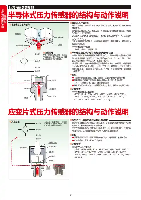
半导体式压力传感器的结构与动作说明应变片式压力传感器的结构与动作说明●半导体隔膜式压力传感器的结构与动作说明●特点●传感器芯片的结构半导体隔膜式压力传感器采用双重隔膜方式,由直接与测量介质接触的高耐腐蚀性金属隔膜(相当于Hastelloy哈氏合金C-22、SUS316L等)与通过封入的硅油检测压力的硅芯片(硅隔膜)构成。
通过压力导入口直接与测量介质接触的是SUS316L隔膜(或相当于Hastelloy哈氏合金C-22等),介质(空气、水、油及其他)不会浸入其中,能够稳定测量。
[连接螺丝的形状为G3/8时,与配管间采用O型圈密封(氟橡胶)。
]●可以制作能够测量正压、负压、连成压、绝对压力的各种传感器元件●直接接触介质的受压部可以采用相当于Hastelloy哈氏合金C-22、 SUS316L的材料制作,因此,耐腐蚀性能优良●用于检测压力的硅芯片,其隔膜厚度较大,因此,具有优良的耐压性能●半导体隔膜式压力传感器 VESW , VESX , VESY , VESZ , VHR3 , VHG3 , VAR3 , VAG3 , VPRNP , VPNPR , VPNPG , VNF , HS1 , HV1 , AS1 , AV1 , NS1 , NV1 , VESI , VESV , VSW2 , VST 等●应变片式压力传感器 VSD4 , NSMS-A6VB , HSSC , HSSC-A6V , VHS , VHST , HSMC2, HSMC , VPE , VPB , VPRT , VPRTF , VPRQ , VPRQF , 0VPVT , VPVTF , VPVQ , VPVQF , VPRF , VFM , VF , VFS , VTRF , VPRF2 , VPRH2 等硅芯片受压部(硅隔膜)与通常的IC制作工艺相同,利用杂质扩散原理形成硅应变片。
当向硅芯片施加压力时,电阻应变片的电阻值会随着其变形而改变,并转换为电信号。

压力传感器使用说明一、概述二、产品特点1.高精度:采用先进的传感器技术,能够以毫巴级的精度进行压力测量。
2.快速响应:具备快速响应的能力,能够实时反馈压力变化。
3.高可靠性:采用优质材料和稳定的电路设计,具备较高的可靠性和耐用性。
4.多种接口:支持多种数字和模拟接口,方便与其他设备的连接。
三、使用方法1.连接电源:将压力传感器与电源进行连接,注意正确连接正负极。
2.连接输出接口:根据实际需要,选择合适的数字或模拟输出接口,并与其他设备进行连接。
3.安装位置选择:根据实际应用情况,选择合适的安装位置,并确保传感器与被测物体表面充分接触。
4.初始化设置:根据实际需求,对传感器进行初始化设置,如量程范围、采样频率等。
5.数据读取:通过连接的接口,读取传感器输出的压力数值。
四、注意事项1.使用环境:应避免在高温、高湿、强腐蚀性环境中使用,以免影响传感器的性能。
2.防尘防水:如需在粉尘多或容易受潮等环境中使用,建议对传感器进行防尘防水处理。
3.振动保护:传感器在使用过程中应尽量避免受到强烈的振动,以免影响测量结果的准确性。
4.清洁维护:定期对传感器进行清洁维护,以确保传感器表面光滑无脏污,维护其测量准确性。
5.防电磁干扰:传感器与其他电磁设备的距离应保持一定的安全距离,以免受到干扰影响读取结果。
6.输电线路:如需将传感器连接到较远的距离,应选择合适的输电线路,避免信号损失或干扰。
五、常见问题及解决方法1.传感器无输出信号:检查电源连接是否正确,检查输出端口是否与其他设备连接正常。
2.输出信号不稳定:可能是传感器与被测物体连接不良,或者是环境干扰较大,需要重新连接或更换安装位置。
3.测量结果不准确:可能是传感器初始化设置不正确,或者是传感器老化等原因,需要重新设置或更换传感器。
六、维护保养1.定期清洁:使用软布蘸取少量清洁液轻擦传感器表面,不要使用具有腐蚀性的清洁剂。
2.频繁使用:如果需要经常使用传感器进行压力测量,建议定期校准和检查传感器的性能,确保测量结果的准确性。
APPLICATONSThe G2 pressure transducer combines performance with value to meet the demanding needs of the original equip-ment manufacturer in applications found in:• Off-road Equipment• Construction Machinery • Performance Racing • Railroad/Transportation • Compressor Control • HVAC and Refrigeration • Agricultural Implements• Process Automation and Control • Hydraulic & Pneumatic Sensing • Pump Monitoring FEATURES• 1% Total Error Band Accuracy • Broad Temperature Capability • All-welded pressure construction • High EMI/RFI rating• Ranges 30 psi through 20,000 psi • IP 67 Ingress rating • Diagnostic railsPERFORMANCE SPECIFICATIONSRef. Condition 21°C ±1°C (72°F ±2°F)Accuracy:Total Error Band includes combined effects of temper-ature, non-linearity (Terminal Point Method), hysteresis,non repeatabilty, zero offset and span setting errors ±1% of Span:From –20 to 85ºC (–4 to 185ºF)±1.5% of Span:From –40 to –20ºC (–40 to –4ºF)±1.5% of Span:From 85 to 125ºC (185 to 257ºF)Note:Static accuracy ±0.25% of span BFSL (Best Fit Straight Line Method); includes non-linearity, hysteresis and non-repeatable effects at reference temperature 72°F (21°C)Stability:Less than ±0.25% span/year Durability:Tested to 50 million cyclesENVIRONMENTAL SPECIFICATIONSTemperature:Compensated –40 to 125°C (–40 to 257°F)Operating –40 to 125°C (–40 to 257°F)Storage –40 to 125°C (–40 to 257°F)Humidity:0 to 100% R.H., no effectFUNCTIONAL SPECIFICATIONSSelect from over 25 pressure ranges starting at 30psi and running through 20,000 psi gauge.Compound (vacuum & pressure) ranges are also available, see “To Order” on back.Overpressure (F.S.): Proof Burst 750 psi & below 200% F.S. 1000% F.S. 1500 psi 200% F.S. 500% F.S. 3000 psi 200% F.S. 500% F.S. 5000 psi 150% F.S. 500% F.S. 7500 psi 120% F.S. 500% F.S. 10,000 psi 120% F.S. 240% F.S. 20,000 psi 120% F.S. 240% F.S.Vibration:Random vibration (20 g) over tempera-ture range (–40° to 125°C). Exceeds typical MIL.STD. requirements Shock:100gs, 6 msDrop Test:Withstands 1 meter on concrete 3 axis Response Time:Less than 1 msecWarm-up Time:Less than 500 msec typical Position Effect:Less than ±0.01% span, typicalELECTRICAL SPECIFICATIONSOutput Signals Available:Supply Voltage Output Excitation Current 0-5 Vdc, 3 wire 9-36 Vdc 5mA 0-10 Vdc, 3 wire 14-36 Vdc 5mA 1-5 Vdc, 3 wire 9-36 Vdc 4mA 1-6 Vdc, 3 wire 9-36 Vdc 4mA 0.5-4.5Vdc, 3 wire 9-36Vdc 4mA Ratiometric Output:0.5-4.5 Vdc, 3 wire 5 Vdc ±0.5 Vdc 3.5mA Current Output:4-20mA, 2 wire 9-36 VdcReverse Polarity & Miswired Protected: Yes Insulation Breakdown Voltage:100 VacInsulation Resistance:Greater than 100 megohms at 100 VdcCE Marked:Per DoCEMC Directive 2004/108/ECIEC/EN 61326-1:Edition 1.0 IndustrialIEC/EN 61326-2-3:Edition 1.0 Annex BB Industrial PED DirectiveThe Ashcroft ®Type G2†pressure transducer has been specifically designed with the high volume OEM in mind.A ±1% Total Error Band accuracy is accom-plished by marrying a high performance ASIC to a very stable, field proven polysilicon thin film pressure sensor. The sensor is electron beam welded to a pressure fitting of stainless steel, which provides excellent overpressure capability and outstanding durability in thep resence of shock and vibration. The circuitry is held within an internal cage and housed in an enclosure of reinforced Nylon.LOOK FOR THIS AGENCY MARK ON OUR PRODUCTSCable ConnectionHirschmann ConnectionMetri-Pack ConnectionFlying Lead Connection。
pg-irt1602说明书
【产品名称】红外体温计
【商品名/商标】
攀高
【结构与组成】攀高红外体温计主要由外壳、液晶屏、传感器及控制电路组成。
测量范围:34℃-43℃。
测量时间:约2秒。
测量距离:3-5cm。
【适用范围】
通过测量耳腔或额头热辐射来显示被测对象的体温。
【用法用量】本品有三色背光识别五种情景。
准确检测身体健康情况,当测量结果处于橙色偏高温或者红色高温时,会发出“哔哔”的警报提示。
方便老人孩子使用。
【注意事项】<34.0°C 红色背光加LO标识,表示超低温;>43.0°C红色背光&HI标识,表示超高温。
【生产厂家】深圳市攀高电子有限公司
附加说明:
攀高红外体温计主要由外壳、液晶屏、传感器及控制电路组成。
通过测量耳腔或额头热辐射来显示被测对象的体温。
本品有三色背光识别五种情景。
准确检测身体健康情况,当测量结果处于橙色偏高温或者红色高温时,会发出“哔哔”的警报提示。
方便老人孩子使用。
ABP2 SERIESBASIC BOARD MOUNT PRESSURE SENSORSThe calibrated/compensated ABP2 Series offers different configurations to choose the right sensor, with the right performance, at the right price, foryour application.FEATURES• Wide operating pressure ranges• Extended operating and compensated temperature ranges • Low Total Error Band• Industry-leading accuracy • Ultra-low power consumption • High burst pressures • Variety of pressure ports • Food grade compatible• Harsh media compatible with flourosilicone gel • Meets IPC/JEDEC J-STD-020E-MSL 1• NSF-169, LFGB, and BPA compliant materials • RoHS and REACH compliant materials •Suitable for portable IoT applicationsNOTICEThis is a Sneak Peek of a new product that isscheduled to be introduced to general sales in Q2 2020. This document contains preliminary specifications that are subject to change. Toobtain a product sample, please contact the Global Product Manager at *************************, +91-9011495648.ABP2 Series008344-5-EN | 5 | 5/21© 2021 Honeywell International Inc.NOTICE: EVALUATION PRODUCTSTHESE PRODUCTS ARE PROTOTYPE PRE-PRODUCTION ITEMS THAT HAVE YET TO COMPLETE ALL PHASES OR PRODUCT RELEASETESTINGS AND ARE FOR CUSTOMER EVALUATION ONLY. THESE ITEMS ARE SOLD “AS IS” WITHOUT WARRANTY EXPRESSED OR IMPLIED, INCLUDING THAT OF MERCHANTABILITY OR FITNESS FOR A PARTICULAR PURPOSE. IN NO EVENT WILL HONEYWELL BE LIABLE FOR ANY CONSEQUENTIAL, SPECIAL, OR DIRECT DAMAGES.PRELIMINARYThis publication does not constitute a contract between Honeywell and its customers. The contents may be changed at any time without notice. It is the customer’s responsibility to ensure safe installation and operation of the products. Detailed mounting drawings of all products illustratedare available upon request.PRODUCT NOMENCLATUREABP2 SERIESBASIC BOARD MOUNT PRESSURE SENSORSHoneywellAdvanced Sensing Technologies 830 East Arapaho Road Richardson, TX 75081 /ast1。
SENSORS FOR FOOD AND LIFE SCIENCES.TP - Series “Smart”Pressure TransmitterIntroductionThe Anderson-Negele “TP” series pressure transmitter is a microprocessor-based sensor specifically designed for sanitary fluid process applications in the Life Sciences industry. This product provides an extremely high level of performance combined with the flexibility of digital communication via the “HART” protocol. The “TP” series can be specified in several configurations including high temperature models that are available in direct or remote mount variations. The high temperature direct mount is also recommended for applications where a horizontal orientation is re-quired for display viewing, such as tank tops and overhead lines. All models comply with UL, “intrinsically safe” requirements for Class 1, Div. 1, Groups A-D. The units may be ordered with any of our wide variety of sanitary process fittings.The “TP” series simultaneously outputs an analog 4-20 mA signal while communicating digitally with a hand-held communicator or other “HART” host device. This allows configuration of parameters such as range, engineering units, tagging info, and other device specific information, from any accessible point inthe output loop. The analog output can even be “trimmed” or calibrated while online, if required. Also retained are internal, non-interactive zero and span analog adjustments. This provides the user with the immediate performance enhancements of this new product, with future compatibility with the “HART” protocol.As with all Anderson-Negele sensors, the “TP” series is designed to be cleaned and steam sterilized in place. The optional LCD display can be factory scaled to linearprocess engineering units, mA output, or 0-100%.2ANDERSON INSTRUMENT COMPANY 156 Auriesville Road Fultonville, NY 12072Phone 800-833-0081Fax 518-922-8997************************Tech. Support:*******************************Phone 800-833-008103705 / 2.0 / 2015-03-20 / PW / NAKEY MODEL #STYLE 0 Standard, Direct Mount Housing 1 Standard w/QDR 2 High Temp (direct mount)4 3 High Temp (remote mount)1,4 4 High Temp (direct mount) w/QDR* 4 5 High Temp (remote mount) w/QDR* 4SENSOR TYPE 1 PSIG 2 PSIA 3 PSIG (overpress./shift high) 4 PSIA (overpress./shift high)UPPER RANGE LIMIT (URL) 1 50 psig/psia 2 100 psig/psia 3 200 psig/psia 4 300 psig/psia 5 500 psig 6 1000 psig PROCESS CONNECTION 002 3/4" Tri-Clamp 3 016 1-1/2" CB "I" (male) 004 1-1/2" Tri-Clamp 017 2" CB "I" (male)005 2" Tri-Clamp 027 1-1/2" G&H "H" Line (male) 010 1-1/2" APC "K" 028 2" G&H "H" Line (male) 011 2" APC "K"123 1-1/2" CPM FlushmountCUSTOM CONFIGURATION000 Standard Configuration XXX Custom Configuration DISPLAY0 No Display B BAR G PSIG 2 R mAA PSIAQ Percent (%)MOUNTING1 Direct mount (Style 0, 1,2 or 4)Options listed below apply to Style 3 & 5 ONLY : A 5' Poly L 5' SS B 10' Poly M 10'SS C 15' Poly N 15' SS D 20' Poly P 20' SS E25' PolyQ 25' SSDIAPHRAGM MATERIAL1 316L Stainless Steel (Standard)2 Hastelloy "C" (Not Available in Connection 002)T P P1 Pipe/Wall mount bracket included with remote mount option (Style 3)2Vacuum shown as (-) PSIG for compound ranges 3Not available with Style 2 or 34Not available with Process Connection 002NOTE: Compound Range Ordering Examples: For 30-0-50 psig, select 50 psig URL For 30-0-60 psig, select 100 psig URL * UL Certification for Intrinsic Safety Pending。
MCU12单片机压力传感器模块使用说明一、线路及各端口1、线路图可参阅模块丝印实际线路。
2、±12V电源端分别接±12V电源。
3.输出端为压力传感器通过放大器放大的实际电压值。
4、输入端是报警电路的控制端。
二、使用说明(以实际电子秤为例)1、压力传感器空载时输出电压为V零。
本模块设定为0.1V以下。
2、压力传感器满载时(200g=10砝码),输出电压为V满,本模块设定为4.5V至5V之间。
3、有效输出电压V有效,等V满减去V零。
例:V零为0.1V,V满在200g时为4.6V,那么 V有效=4.6V-0.1V=4.5V4、根据上述已知满载时V有效电压为4.5V,那么每克输出电压也就知道了。
V每克=4.5V÷200g=0.0225V/g5、现将一个未知重量物体置于秤上已知输出电压Vx为3.6V,求X物体重量为多少?X(g)=3.60.1155.55 0.0225/0.0225/Vx V V Vg V g V g--=≈零6、单片机与压力传感器模块连接如图所示:通过A/D转换读入V零,V满进行校准求出V每克,然后读出 Vx电压值就可求出X物体重量了,并以XXX.XX克显示在单片机显示屏上。
7、本模块设定了一个报警电路OV 低电平关,5V(高电平)报警,它的输入端与单片机输出端口连接,当电子秤称重超过200g可报警。
设定值可自己设定。