安格斯AC-2工业冷冻机说明书
- 格式:pdf
- 大小:863.20 KB
- 文档页数:13

真空冷冻干燥机说明书(参考用)产品名称:真空冷冻干燥机产品型号:LYO-8(CIP)产品标准号:Q/NGAC1-031A搁板有效总面积:㎡最大捕水量:150Kg总功率:47KW外形尺寸:4915×2500×2960mm总重量:5200Kg冻干原理真空冷冻干燥就是把含有大量水分物质,预先进行降温冻结成固体,然后在必然真空条件下使水蒸汽直接从固体中升华出来,而物质本身剩留在冻结时的冰架中,因此它干燥后体积不变、疏松多孔冰在升华时要吸收热量,引发产品本身温度下降而减慢升华速度,为了增加升华速度,缩短干燥时刻,必需要对产品进行适当加热。
整个干燥进程是在较低温度下进行的。
冷冻干燥有下列长处:1、制品在冻干腔室内的无菌状态下完成干燥、解吸附水分和全压塞等操作。
2、适于液体加工,操作简便,作业进程容易简化,无菌环境便于控制。
3、能除去物质中95~99%的水分,稳固性好,易于长期保留药物的有效成份。
4、许多生物制品、药品、食物在水和热的作用下很容易产生变性或分解,为了长期保留,最适宜的方式是在低温下冻结干燥。
5、制品中水分的去除,无热处置进程。
6、制品冻干后的体积、形状大体不变,物质呈干粉状态,无干缩。
7、在冷冻干燥进程中,微生物的生长和酶的作用无法进行。
因此能维持原来的性状。
真空冷冻干燥系统操作规程:开机前预备:一、确认冻干箱内测温探头已安放准确二、确认冷凝器内化霜水已排放干净三、确认冷却水、紧缩空气、总电源稳供给冷冻干燥手动操作:1、旋开控制柜钥匙开关,进入冷冻干燥操作界面,点击“手动”,进入手动操作系统。
2、开循环泵1或循环泵2,确认泵的出口压力(~)左右。
3、开紧缩机一、板冷阀1,紧缩机二、板冷阀2,对制品进行预冻(按照预冻速度,选择开一台或两台紧缩机)。
4、当制品温度达到工艺所要求的温度后,恒温(即维持目前温度)一段时刻(由工艺决定,一般2~3小时)5、恒温结束后,对冷凝器进行制冷(当用一台紧缩机制冷制品时,另一台要同时制冷冷凝器),即关板冷阀一、板冷阀2,开冷凝器阀一、冷凝器阀2。

C H R I S TA L P H A 1 – 2 型冷冻干燥机使用说明书目录1·导言2·应用范围3·安装3·1 3·2 3·3 电源插座除霜水真空泵排气4·运转及操作能说明4·1 电源“Netz”开关4·2 温度毫巴“℃mbar”开关4·3 “C/ mbar”按钮5·连接TPR 250真空度传感器6·冷冻干燥一般知识6·1 冷冻6·2 主干燥6·3 后干燥6·4 干燥终结6·5 降霜7·在冷阱室或者是机器外(例如:冷冻冰箱)中冷冻,然后在搁板上干燥8·在真空下或隋性气体下关闭瓶子的压盖装置9·外冷冻(例如在冷浴中)并且干燥烧瓶中的液体。
10·机外冷冻(例如:在冷浴),干燥48接头干燥格筛上的安瓿里的液体。
11·机器的保养与维护11·1 真空泵11·2 排气过滤器11·3 冷阱室11·4 真空橡胶密封阀11·5 液化器12·故障提示12·1 断电12·2 真空度不够12·3 TPR 250真空度计校准12·4 冷阱或搁板温度达不到13·ALPHA 1-2技术规格1·导言什么是冷冻干燥?冷冻意味着从冷冻的物质中驱出水份,干燥是在真空状态下直接把结冰的水升华为气态达到的,被冻干的材料温度低于-10℃。
冷冻干燥的目的是干燥保存易脱水的产品,在加水以后要恢复原材料的特性。
在非常低温的状况下达到干燥,蛋白质保持无水,而其它主要的化学键保持质的量不变。
通过冷冻干燥,组织、组织提取物、细菌、疫苗及血浆之类的材料,成为干燥状态,从而不会发生酶的、细菌的及化学的改变。
可以说,冷冻干燥是保存生物特性敏感的组织及组织成份的最佳方法。
有关于冷冻机的使用说明书摘自-1. 目的:指导设备使用人员能正确对设备进行操作。
2. 范围:适用于所有冷冻机操作人员。
3. 如何操作冷冻机3-1要冷却货柜的内部(1)在起动发动机前,确保ON/OFF开关(前室和后室)被打到OFF。
(2)起动发动机,让其充分预热。
(3)按ON/OFF开关,运行指示LED点亮,并且冷冻机将运行。
显示器将显示货柜内部当前的温度。
(4)当货柜内部温度达到设定温度时,冷冻机将自动停止制冷,当温度再次上升时,冷冻机将自动复制冷。
即使制冷停止时,运行指示LED也保持点亮。
3-2停机再次按ON/OFF开关,制冷运行将停止,并且运行指示LED将会熄灭。
注意:*如果运行指示LED闪烁,冷冻机有问题。
如果发生任何其它类型的问题,货柜内的温度将上升。
在这种情况下,立即采取适当措施保护货物,并与“电装”授权的维修站联系,对冷冻机进行检查和修理。
*如果冷冻机已经有一周或更多时间没有使用,应以空转速度试运转5分钟或更长时间。
如果不执行运行,可能会损坏压缩机。
注释:*当后室的冷却方式为冷藏风扇方式时,若按下REAR(后室)开关,前室侧的冷冻机自动开始运行。
停止时一定要先关闭REAR(后室)。
*冷冻机要在发动机开关关掉之前停机。
这使得下次起动发动机比较容易。
*先前使用的温度设定被存储在控制面板的存储器中。
要在显示器上显示出当前温度设定时,按一下TEMP(温度)开关。
4. 改变货柜温度设定4-1 如何显示温度设定(1)按一次TEMP(温度)开关(∧或∨)。
*显示器将显示出当前设定的温度。
*5秒钟后,显示器将自动返回指示货柜内的温度。
4-2 如何更换FRONT(前室)侧温度设定(1)按一次MEMO(存储)开关的∧。
*显示前室侧的温度设定,“℃”将闪烁。
(2)按二次TEMP(温度)开关(∧或∨)。
*显示屏上的温度设定将闪烁。
(3)在温度设定值闪烁的同时,通过按TEMP(温度)开关(∧或∨),将设定值改变到想要的温度。
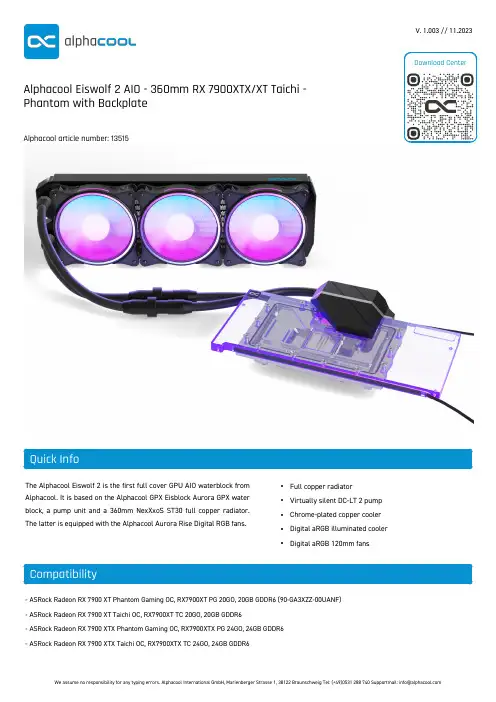
The Alphacool Eiswolf 2 is the first full cover GPU AIO waterblock from Alphacool. It is based on the Alphacool GPX Eisblock Aurora GPX water block, a pump unit and a 360mm NexXxoS ST30 full copper radiator.The latter is equipped with the Alphacool Aurora Rise Digital RGB fans.•Full copper radiator •Virtually silent DC-LT 2 pump •Chrome-plated copper cooler •Digital aRGB illuminated cooler •Digital aRGB 120mm fans- ASRock Radeon RX 7900 XT Phantom Gaming OC, RX7900XT PG 20GO, 20GB GDDR6 (90-GA3XZZ-00UANF)- ASRock Radeon RX 7900 XT Taichi OC, RX7900XT TC 20GO, 20GB GDDR6- ASRock Radeon RX 7900 XTX Phantom Gaming OC, RX7900XTX PG 24GO, 24GB GDDR6- ASRock Radeon RX 7900 XTX Taichi OC, RX7900XTX TC 24GO, 24GB GDDR6V. 1.003 // 11.2023Alphacool Eiswolf 2 AIO - 360mm RX 7900XTX/XT Taichi -Phantom with BackplateAlphacool article number: 135151x Eiswolf 2 (pump, cooler, backplate) 1x Radiator NexXxoS ST30 360mm3x Fans Rise Aurora 120mm1x Montage Set GPU Cooler12x M3x6mm Screw 12x M3x30mm Screw1x PWM Cable Y-Adapter 1x aRGB Adapter1x Plug toolThe Alphacool Eiswolf 2 is the first full cover GPU AIO waterblock from Alphacool. It is based on the Alphacool GPX Eisblock Aurora GPX water block, a pump unit and a 360mm NexXxoS ST30 full copper radiator. The latter is equipped with the Alphacool Aurora Rise Digital RGB fans.Fullcover Waterblock?The Eiswolf 2 graphics card AIO water block not only cools the G PU with liquid but also all relevant components that require active cooling. This includes the graphics memory, the VRM and, if necessary, other components that require direct cooling. By using the Eisblock G PX Aurora water cooler, the cooling capacity is identical to that of a DIY graphics card water cooler.Chrome-plated copperThe cooler is made entirely of chrome-plated copper. A chrome plating is much harder than a nickel plating and therefore less sensitive to acids, scratches and damage. It completely eliminates the risk of chipping nickel plating. Additionally, chrome plating looks much more homogeneous and provides a shine that cannot be achieved by nickel plating. Chrome-plated coolers have previously only been used in the industrial sector in areas where extreme influences act on the coolers.PumpThe Eiswolf 2 has a pump unit in place of the normal connection terminal. This pump unit houses the DC-LT 2 pump. An improved and quieter version of the well-known DC-LT Low Noise Ceramic Pump. Despite looking rather large, the pump unit is only 5 mm wider than a normal connection terminal.Fittings and TubingAs with all new AIO units, Alphacool uses only TPV hoses from the Enterprise Solution range for (usually reserved for servers and workstations) in the Eiswolf 2. The tubing is made of EPDM/PP and are extremely heat-resistant, durable, and free of plasticizers. All fittings are also based on the Enterprise Solution range and match the TPV hoses perfectly.ExpandabilityBy using the quick-release fastener, the Eiswolf 2 can be connected to another Alphacool AIO unit to achieve a larger loop in seconds. Alphacool offers various prefilled components with which the loop can be easily extended. For safety reasons, the quick-release fasteners are firmly screwed together and not just plugged together.Lighting and fansThe Eiswolf 2 cooler has a digital RGB LED lighting, also called addressable RGB LEDs. They run along the entire back of the graphics card cooler and provide complete illumination of the water cooler. The pump unit is more discreet and offers a green glowing logo for Nvidia and a red glowing logo for AMD cards. The name "Eiswolf" on the pump unit remains unlit, discreetly in the background. The fan used is the Aurora Rise with 120mm. Due to the special blade design, the fan is extremely quiet and the addressable RG B LEDs provide brilliant illumination. The Alphacool Aurora Rise fan convinces with a max. static pressure of 3.17mm/H2O and offers a max. air flow of 119.8m3/h. The PWM control allows the fan to be controlled over a wide speed range. In addition, it offers a zero control. It can therefore be regulated down to 0 rpm and then starts with approx. 350 rpm.NexXxoS RadiatorAs with all AIO units, Alphacool uses radiators from the world renowned NexXxoS series. The full copper radiators offer a much higher cooling capacity than aluminium radiators and have contributed significantly to Alphacool's worldwide success.The combination of all of the components results in a solution that is as simple as an AIO solution to install, but with the performance of a pre-assembled and prefilled custom loop.Technical note!Due to long storage times and various transport routes, the liquid in the Eiswolf 2 AIO remains still for a long time. The ingredients of the liquid can therefore deposit and lead to a brownish discoloration. As soon as the pump starts operating, the ingredients mix again and the liquid should regain an approximately clear color. This is not a reason for complaint as neither the performance nor the function of the AIO are restricted by this. If the discolouration of the cooling liquid does not disappear after the AIO has been put into operation, please contact our support team via E-Mail (******************).Youwillreceivequickanduncomplicatedhelpthere.Drawing。
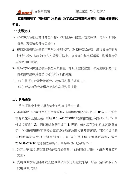
感謝您選用了“安格斯”冷凍機,為了您能正確高效的使用,請詳細閱讀說明書。
一、安裝要求:1、冷凍機安裝前請選擇地基平穩,四周空曠,暢通及避免腐蝕、污染、日曬、雨淋,方便安裝維修之場所;2、根據冷凍機製冷量選用匹配的冷卻水塔。
冷水機管路配管,請根據機身喉尺寸進行安裝,切勿將冷卻水管尺寸縮小,這樣會引起高壓超載,影響製冷效果及增加耗電量;3、風冷式冷凍機請必須安裝在距離牆壁一米以上空間位置,以免造成散熱不良引起高壓過載影響製冷效果及增加耗電量。
注:(1)電源負載及接地部分,請依照相關法規施工!(2)新安裝的冷凍機冷凍水管必須包保溫層!二、開機準備首次運轉冷凍機必須先檢查下列事項是否正確:1、電源電壓及相數是否符合型號規格,請對照銘牌所示。
[注3HP以上冷凍機電源是採用三相五線,電壓380~415V/50HZ電源相位線分另為R、S、T,中性線(零線)N,接地導線為雙色線用E表示;機內設有錯缺相保護器,當在第一次開機時出現不亮燈或亮紅燈並顯示故障代碼及警號時,可將相線任意兩相對換接妥後合上開關即可;3HP以下冷凍機採用單相電源,電壓220-240V/50HZ電源相位線為L,中線為N,地線為E。
]2、冷凍水喉及冷卻循環水喉是否接通管路,並保持閥門打開;(請參考安裝示意圖)3、先將冷凍水箱加滿水或其他冷凍介質後方可啟動水泵;(注:請根據要求來配用冷凍介質)4、請留意冷卻水泵運行方向及水塔風機是否逆轉(如水泵是三相,逆轉須將電源相位線中任意二相對換,接妥後再把開關合上即可)。
三、操作順序1、首先將總電源開關開啟ON位置;2、開啟冷卻水塔和冷卻水泵開關,此時注意冷卻水出入口閥門必須打開(注:風冷式冷凍機無須配備冷卻水塔)。
3、再開啟冷凍機運行開關,此時冷凍水泵開始運行,請注意冷凍水出入口閥門必須打開,經延時開關延時後壓縮機會自動運行,請查視及調節所需溫度。
4、關機時,請依相反的順序操作關機即可。
四、面板示意圖及操作說明1、開機:①打開冷凍機電箱內的空氣開關;②按“PUN”啟動鍵,開啟冷凍機,此時冷凍水泵啟動;③按“COMP1”壓縮機1鍵、“COMP2” 壓縮機2鍵開啟壓縮機(如:只有一台壓縮機時,按“COMP2” 壓縮機2鍵無效。
双螺杆制冷机组说明书全文共四篇示例,供读者参考第一篇示例:双螺杆制冷机组是一种新型高效节能的制冷设备,被广泛应用于各种工业和商业领域。
本说明书将详细介绍双螺杆制冷机组的工作原理、结构组成、技术特点以及维护保养方法,希望能为用户提供帮助。
一、工作原理双螺杆制冷机组是利用螺杆压缩机将低温低压的制冷剂吸入,经过螺杆机组内部的高速旋转,通过增压和压缩,将制冷剂排出高温高压,然后制冷剂通过冷凝器散热释放,温度降低,再经过膨胀阀膨胀降温,最终形成制冷效果。
二、结构组成双螺杆制冷机组通常包括螺杆压缩机、冷凝器、蒸发器、冷却塔、电控系统等组成部分。
1. 螺杆压缩机:负责将低温低压的制冷剂吸入,进行增压和压缩。
2. 冷凝器:将高温高压的制冷剂通过散热转化为高温高压气体。
3. 蒸发器:制冷剂通过膨胀阀进入蒸发器,与物体交换热量,并吸收物体内部的热量,形成冷却效果。
4. 冷却塔:用于冷却冷却剂循环水。
5. 电控系统:控制整个机组的运行和停止,保证机组的正常运行和节能效果。
三、技术特点1. 高效节能:双螺杆制冷机组采用螺杆压缩机,比传统往往的往往很重的闭式制冷机更为高效节能,能显著降低能耗和运行成本。
2. 稳定可靠:双螺杆压缩机具有结构简单、运行平稳、噪音低、寿命长等优点,能够稳定可靠地工作。
3. 温度控制精确:通过先进的电控系统,能够实现对温度的精确控制,保证制冷效果和产品质量。
4. 易安装维护:双螺杆制冷机组结构简单,安装调试简便快捷,且维护保养方便,降低了使用成本和维修成本。
四、维护保养方法1. 定期检查清洁:定期检查和清洁蒸发器、冷凝器、滤网等部件,保持散热效果良好。
2. 注重润滑保养:定期给螺杆压缩机加润滑油,保证螺杆机组的正常工作。
3. 注意温度控制:定期检查和校准电控系统,确保温度控制精确可靠。
4. 系统排气排水:定期排放系统内部的气体和水分,保持系统的清洁干净。
第二篇示例:双螺杆制冷机组是一种专门用于商业建筑和工业设施的制冷设备,其主要功能是将热量从内部环境排出,以保持室内环境的舒适温度。
全滚动轴承单机双级系列螺杆式制冷压缩机组使用说明书中华人民共和国THE PEOPLE’S REPUBLIC OF CHINA 大连冷冻机股份有限公司DALIAN REFRIGERATION CO.,LTD.承蒙惠购冰山牌制冷设备,谨此表示衷心感谢!在使用本设备之前,务请详细阅读本使用说明书,以便掌握正确的安装、调试及操作方法,这对机器正常、可靠地运转十分重要。
在设备正常使用后,也请妥善保管使用说明书,以便日后参考。
因产品改进和更新,本说明书内容可能会有所改变,恕不另行通知。
目录1 概述 (1)1.1产品特点、用途及使用条件 (1)1.2产品型号的组成及其代表意义 (1)2 全滚动轴承单机双级螺杆压缩机组的组成及工作原理 (1)2.1全滚动轴承单机双级压缩螺杆压缩机组系统原理 (2)2.2全滚动轴承单机双级螺杆压缩机组的主要零部件 (3)2.2.1全滚动轴承单机双级螺杆压缩机 (3)2.2.2联轴器 (3)2.2.3吸气过滤器 (3)2.2.4排气止回截止阀 (4)2.2.5能量调节电磁阀组 (4)2.2.6油分离器 (4)2.2.7油冷却器 (4)3机组主要参数 (6)3.1机组主要技术数据 (6)3.2性能参数 (8)4安装及开机前的准备 (8)4.1安装 (8)4.1.1基础 (9)4.1.2 机组的吊装 (9)4.1.3机组的安装 (9)4.1.4 管路连接 (9)4.1.5电气接线 (9)4.1.6 联轴器找正 (9)4.2开机前的准备 (10)4.2.1 系统排污 (10)4.2.2 系统试漏检验 (10)4.2.3系统真空试验 (11)4.2.4加油 (11)4.3充入制冷剂 (11)5操作 (11)5.1正常开机 (11)5.2正常停机 (12)5.3运转过程中注意事项 (12)5.4停机期间保护措施 (12)6.机组故障及消除办法 (12)7 检修 (14)8 液态工质冷却螺杆式制冷压缩机组 (14)8.1结构特征与工作原理 (14)8.2安装与使用 (16)附表1冷冻机油各品种的应用(GB/T16630-1996) (16)附表2R717(NH3)热力性质表 (17)附表3R22(CHF2C L)热力性质表 (18)1 概述本说明书介绍了大连冷冻机股份有限公司生产的全滚动轴承单机双级螺杆制冷压缩机组的结构特征、性能参数、操作方法和维修保养,以指导用户及专业制冷技术人员正确地使用。
一、安装要求:冷冻机安装前请选择地基平稳,四周空旷,畅通及避免腐蚀、污染、日晒、雨淋,方便安装维修之场所,根据冷冻机制冷量选用匹配的冷却水塔。
冷水机管路配管,请根据机身喉尺寸进行安装,切勿将冷却水管尺寸缩小,这样会引起高压过载,影响制冷效果及增加耗电量,风冷式冷冻机请必须安装在距离墙壁1m以上空间位置,以免造成散热不良引起高压过载影响制冷效果及增加耗电量。
注:1、电源负载及接地部分,请依照相关法规施工!2、新安装的冷冻机冷冻水管必须包保温层!二、操作方法首次运转必须先检查下列事项是否正确:1.电源电压及相数是否符合型号规格,请对照铭牌所示。
[注3HP以上冷冻机电源是采用三相五线,电压380~415V/50HZ电源相位线分另为R、S、T,中性线(零线)N,接地导线为双色线用E表示,内设有错缺相保护器,当在第一次开机时出现不亮灯或亮红灯并显示故障代码及警号时,可将相线任意两相对换接妥后合上开关即可;3HP以下冷冻机采用单相电源,电压220-240V/50HZ 电源相位线为L,中线为N,地线为E。
]2.冷冻水喉及冷却循环水喉是否接通管路,并保持阀门打开;(请参考安装示意图)3.先将冷冻水箱加满水或其它冷冻介质后方可启动水泵;(注:请根据要求来配用冷冻介质)4.请留意冷却水泵运行方向及水塔风机是否逆转(如水泵是三相,逆转须将电源相位线中任意二相对换,接妥后再把开关合上)。
三、操作顺序1.首先将总电源开关开启ON位置;2. 开启冷却水塔开关,此时注意冷却水出入口阀门必须打开(注:风冷式无须配备冷却水塔)。
3.再开启冷冻机运行开关,此时冷动水泵开始运行,请注意冷冻水出入口阀门必须打开,经延时开关延时后压缩机会自动运行,请查视及调节所需温度。
4.关机时,请依相反的顺序操作关机即可。
四、面板示意图及操作说明⑴开机:按“PUN”键启动机器:开冷冻泵-----延时(时间可设)------开冷却泵(冷却风机)------按“COMP1”“COMP2”键(“COMP1”“COMP2”可选择开启)------延时(时间可设)-------起动压缩机。

标准文档I R33F0E000控制器使用说明I R33F控制器是集压缩机控制、冷风机控制、温度控制、融霜控制于一体的多功能控制器。
温度设定显示或设定温度,参照以下流程:1)按“S e t”超过一秒,显示设定温度2)按“或“减小或增大设定值。
3)按“S e t”确认。
手动复位报警同时按“”和“超过5秒,可以重新设定手动复位报警。
手动融霜按”5秒以上,进入自动融霜关键点分析和临界点控制(下简称H A C C P)本控制器具有关键点分析和临界点控制功能,它能够监视食品温度,“H A”报警:超高温报警;”H F”报警:断电超时一分钟报警。
显示报警参数:按“S e t”和“或“可进行查看。
H A C C P报警删除:按“和“S e t”超5秒,屏幕出现”r e s”表明已删除。
取消已存报警:按“S e t”和“、“超5秒,即可。
连续循环同时按住“或“超过5秒,启动连续循环功能。
当连续循环设定时间达到或达到最低指定温度,连续循环停止。
设置默认参数当H d n=0时:1.关闭设备2.打开设备3.持续按“”,直到出现”s t d”注:只可为可视值(C或F类)参数设置默认值。
需更详细信息,参阅“运行参数汇总”。
当H d n〈〉0时:1.关闭设备2.打开设备3.持续按“”,直到出现”0”4.利用“、“,在0和”H d n”间选择默认参数。
5.持续按“”,直到出现”s t d”访问C类参数1.同时按“”“S e t” 5秒钟以上,显示屏出现00。
2.利用“、“,直到显示数字22,此密码为允许访问参数。
3.按“S e t”进行确认。
4.显示屏将显示第一个可修改的C型参数代码。
修改参数步骤参照以下修改参数一节访问F类参数1.按“” 5秒钟以上(如果报警被激活,先关掉蜂鸣器),显示屏将显示第一个可修改的F型参数代码。
修改参数步骤参照以下修改参数一节修改参数C型或F型参数显示后,按以下步骤操作:1.利用“、“翻到需要修改的参数。
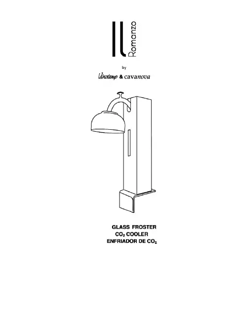
byPARTSYou will need:1.CO2 Froster (included)2.Table attachments: screw and nut (included)3.Teflon washer (included)4.CO2 fitting (included)5.CO2 cylinder/tank (not included)6.2 AA batteries for the LED light (not included, not shown)7.Philips head screw driver (not included, not shown)8.1 ½” adjustable wrench (not included, not shown)Please make sure you have all of these items before installing your new CO2 Froster.WARNING: This product works with liquid CO2 only. Never connect any other compressed gas cylinders with high pressure. A liquid CO2 cylinder with siphon tube is preferred to deliver liquid CO2. If a standard gas CO2 cylinder is used, the cylinder must be placed upside down to deliver liquid CO2. Install this product in a well ventilated area; otherwise a high level of CO2 may accumulate.InstallationPowering the LED Light StripThe LED light strip requires 2 AA batteries. To add the batteries, simply remove the black cover located at the top of the unit.Remove the black cover to access the batteries.Connecting the Unit to theCO2 Cylinder•A black tube is included whichfunnels the CO2 liquid betweenthe glass froster and the CO2tank. At the end of each tube arestainless steel loops which mustbe affixed to both the unit andthe tank.•Place the loop around the connector of the cylinder asshown, prior to connecting the black tube to the tank.• The other end of the black tube should now be looped around the glass froster as shown.• Insert the white Teflon washer provided to the end of the CO2 fitting.• Connect the Glass Froster to the CO2 cylinder using the fitting supplied. Using a wrench, turn the nut clockwise until it is tight.•Next, open the gas flow using the knob located at the top of theCO2 cylinder. Please make surethat the CO2 cylinder sitsvertically at all times. NOTE:Stand to the side of the cylinderwhen opening the cylinder valve.Open the cylinder valve slowly.Mounting the IL‐CO2FROSTYou must attach your new Glass Froster to a level and sturdy surface such as a table or counter top.•Position the Glass Froster near the edge of the surface.•Attach the nut provided to the screw. This will protect yoursurface and add stability.•Adjust the screw located on the underside until it is fastened tothe table or counter top.Using the IL‐CO2FROST•Now that your CO2 cylinder hasbeen installed, press the switchlocated on the upper part of theunit until you see the LED lightstrip illuminate and CO2 beingreleased.•The unit is now ready for use.Place a cup under the spout tofrost. This should only take 2seconds. Promptly remove thecup from the unit. You mayrepeat this process as manytimes as you would like. Werecommend about 3 times percup. After use, it is recommendedthat you close the CO2 cylinderand release any remaining gas bypressing the switch until all CO2has been released.Changing the CO2 CylinderWhen the frosting time exceeds 10 seconds, this is an indication that it is time to change the cylinder. Please follow these instructions carefully:1.Close the shut‐off valve of the cylinder.2.Press the switch of the Glass Froster until all pressure is released.3.Loosen the fitting connecting the unit to the cylinder.4.Finally, connect the unit to the new CO2 cylinder following the instructions outlined onthe previous page.Safety Precautions for the CO2 Cylinder•Gas cylinder contents are under high pressure.•Don't destroy or remove identification tags or labels.•Check to see cylinder valves are protected with protective caps.•Leave caps on until the gas is about to be used.•Do not roll or drop cylinders, or let them bump violently against each other.•Secure large cylinders (125 cu. ft) with a chain or strap positioned around the upper third of the cylinder.•Clear cylinder valve of any dust or dirt before attaching the regulator.•Stand to the side of the regulator when opening the cylinder valve.•Open cylinder valve slowly.•Store cylinders in a well‐ventilated area away from all sources of heat or flames.•Before returning cylinder, close the valve and replace the protective cap.•Mark empty cylinders "EMPTY".•Note: The standard CO2 tank has a valve at the top, the liquid at the bottom and vapor at the top. In order to get liquid, the tank must be placed upside down so the liquid can flow out of the bottom.•Note: Liquid CO2 tanks have a built‐in liquid tube that takes liquid at all times.WARNING•Never loosen the CO2 fitting without first releasing all the CO2 from the unit and closing the cylinder shut‐off valve.•Should a leak occur, close the valve and contact the manufacturer.Precautions1.Keep the cylinder away from all heat sources.2.Do not tamper with the gas flow.3.Prolonged direct exposure may cause scalding of the skin.e the Glass Chiller in a well ventilated location only.5.Keep these instructions for future reference.Contact our customer service at 1‐800‐777‐8466 or *****************TERMS AND CONDITIONSVinotemp International Corp. (“Seller”) and the person or entity that acquires these goods from Seller (“Purchaser”) hereby fully agrees to the following terms and conditions of the sale: Shipping fees are the responsibility of the Purchaser whether freightprepaid or freight collect. Seller assumes no responsibility for the goods sold to the Purchaser once the goods have left the Seller’s premises, including, but not limited to, late delivery by the carrier, or for events caused by any difficulty carrier incurs in attempting to fit the goods into the Purchaser’s designated location due to the size of the goods or any other reason. Purchaser assumes all responsibility for delivery, payment of freight, access, measurement, installation, hook-up, wiring, moving and storage of thegoods. The transportation of all goods is subject to the terms and conditions which the carrier imposes on Purchaser including, but not limited to, additional charges imposed per flight of stairs, and/or additional charges resulting from the carrier’s inability to safely and/or adequately use the building elevator to lift the goods. Any claim for damages incurred during shipment by the carrier of the goods are insured and handled directly with the carrier and must be noted at time of delivery. Any damages due to manufacture defects will be handled directly with Seller, subject to the Limited Warranty, below. If the item is damaged by the freight company, Purchaser may cancel the order only by paying for freight costs both ways and a 35% restocking fee.All sales are final, and unless authorized in writing by the Seller, Purchaser may not return the goods, under any circumstance. If Purchaser refuses to accept the goods, under any circumstance, the Purchaser is liable for the return and cost of freight both ways, and if Seller does take back the goods, there will be a restocking/service fee that is 35% of the purchase price of the goods(product must be in original packaging). If Purchaser returns goods claiming that the goods are defective and goods are found to be in working condition by the Seller, Purchaser is liable for the return and cost of freight both ways plus an a restocking/service fee that is 35% of the purchase price of the goods. Built-to-Order products (including Cabinets, Racking, and Accessories) are non-returnable. Purchaser must notify Seller of non-conforming goods within four days of delivery, after which time all goods aredeemed accepted. If an order has been placed and production has started, cancellation of your order will be a 15% charge. IfPurchaser tenders payment with a check that has insufficient funds (NSF), or stops payment on a check or credit card for anyreason, Purchaser agrees to pay for all costs associated with the Seller’s collection or litigation of such a claim, including without limitation general and special damages, court costs and attorneys’ fees. Finance charges begin the date of invoice. Collection fees plus NSF fee of $50 will be added to your invoice, which you agree to promptly pay. Title to the goods does not pass until payment is received in full by Seller and Seller retains a security interest in the goods until they are paid for in full, however, from deliver, Purchaser will insure the goods and for any damages caused by the goods (eighteen percent (18%) annual rate). Purchaserassumes and must immediately pay any “credit card arbitration” fees which the credit card companies charge during a dispute. Any disputes not resolved within 30 days from the invoice date will be reported to credit reporting agencies.LIMITED WARRANTY: Seller warrants that the goods will be free of defects in materials and workmanship as follows: Furniture style (wood) wine cabinets made in the U.S.: all cooling unit parts for a period of 5 (five) years; cabinetry and labor (uninstalled) for a period of 12 (twelve) months.Metal cabinet wine units: parts and labor for cooling system and cabinetry for a period of 12 (twelve) months.For Designer Series units: parts and labor for a period of 12 (twelve) months from date of sale, compressor parts 5 years.Thermoelectric Units: 90 (ninety) days (including Wine Coolers, Beer Dispensers, Humidor, Portofino Wood Cellars, andRefrigerators).Wine-Mate Split and Ducted Systems and other installed products and parts only for 1 year, no labor. Other Wine-MateCooling Systems are 5 years parts, 1 year labor. Wine Accessories, Racking Systems and Other items are not warranted. There is no warranty on parts purchased separately. If a purchaser claims a product is “defective”, they must obtain a letter from a qualified refrigeration technician at the customers cost, to verify that the unit was installed properly, with proper ventilation and the unit is truly malfunctioning due to manufacture defect.Removal or re-installation of unit is not included in warranted costs. Purchaser’s exclusive remedy is limited, at Seller’s option; to repair or replace defective part[s] with either new or reconditioned part[s]. Purchaser is responsible for shipping the unit pre-paid to designated facility and Seller will pay return shipping charges in the continental United States for items repaired under warranty within 12 (twelve) months from date of sale. Since the natural variation in texture, density, grain, color, tone and shade of wood is unavoidable; Seller does not guarantee the texture, color, tone or shade of the wood: nor does seller guarantee the colorfastness of wood or against peeling, chipping, cracking or scratching. Note: Unfinished wood is subject to warping; all wood surfaces must be sealed before placing cellar into service. Improper repair or placement of the unit will void the warranty. Any third party repair facility must be pre-approved in writing by Seller, before providing replacement parts under warranty.IL Romanzo units: Warranty 90 (ninety) days. Replacement part 12 (twelve) months from the date of sale.Non-New Units (Scratch & Dent/Refurbished/Floor Models), warranty for compressor units is 90 days from your dated invoice and 30 days for thermoelectric units (parts for function only, not cosmetic defects). These units are refurbished and sold as is; Purchaser assumes risks to the quality and performance of goods and assumes the costs of all necessary service or repair not covered herein.Element Grills (via Element Products LLC), grills have a 1 year parts warranty and a thirty day limited parts warranty on grill accessories. Warranty period is from the date of sale (not from shipping, delivery, nor installation).This Limited Warranty does not cover damage due to such things as accident, misuse, abuse, mishandling, neglect, acts of God, fires, earthquakes, floods, high winds, government, war, riot or labor trouble, strikes, lockouts, delay of carrier, unauthorized repair, or any other cause beyond the control of the Seller, whether similar or dissimilar to the foregoing. Seller is not responsible for any damages caused to Purchaser's property resulting from the goods. This limited warranty applies only inside the Continental US (Alaska, Puerto Rico, Hawaii and other territories/countries are not warranted.).Purchaser understands and acknowledges that the goods sold here are wine cellars, cigar humidors, and/or other similar units which house wine or cigars or other items. Purchaser assumes all risk of using these units, including risk of spoilage, humidity variations, temperature variations, leaks, fire, water damage, mold, mildew, dryness and similar and any other perils that might occur.Seller is not responsible for incidental or consequential damages, and there are no warranties, expressed or implied, which extend beyond the Limited Warranty described above. Warranty and liability are non-transferable. The implied warranties of merchantability and of fitness for a particular purpose are hereby expressly disclaimed. Some states do not allow the exclusion of incidental or consequential damages, or a waiver of the implied warranties of fitness and/or merchantability, so the above limitations may not apply to you. This warranty gives you specific legal rights and you may also have other rights which vary from state to state. Seller disclaims any indemnification for claims of infringement of any intellectual property of protectable nature. In the event of any dispute between Seller and Purchaser arising out of or relating to these terms and conditions or to the goods sold generally, Purchaser must first file a written claim with Seller within ten days of the occurrence giving rise to the claim and wait an additional thirty days for a response before initiating any legal action. The sale and all terms are subject to California law. Any legal proceeding arising out of or relating to these terms and conditions or to the goods sold Purchaser shall bring, solely and exclusively in the County of Los Angeles. In no event may Purchaser initiate any legal proceeding more than six months after the occurrence of the event giving rise to the dispute. Seller may make non-payment claims until debt is paid in full.HONEST FEEDBACK: In an effort to ensure fair and honest public feedback, and to prevent the publishing of libelous content in any form, your acceptance of this sales contract prohibits you from taking any action that negatively impacts Seller its reputation, products, services, management or employees, unless you have: (A) first communicated with Seller, and (B) your statement/claim has been substantiated or validated by a judgment. Should you not follow this process, Seller in its sole discretion, will provide you a seventy-two (72) hour opportunity to retract the content in question. If the content remains, in whole or in part, you will immediately be billed US$2,500, as liquidated damages, representing a fair estimation of damages, for it would be impracticable or extremely difficult to fix the actual damages. Should these charges remain unpaid for 30 calendar days from the billing date, your unpaid invoice will be forwarded to a collections firm and will be reported to consumer credit reporting agencies until paid.The above terms and conditions are the only ones governing this transaction and Seller makes no oral representations of any kind. These Terms and Conditions can only be modified in writing, signed by both Purchaser and Seller.To register your product, visit: /Warranty.aspxRegister your warranty within 10 days of receiving the unit.Please be sure to retain your proof of purchase.•Fast frosting of dry glasses and cups•Improves the taste of your drink or cocktail•Compact design requires minimum counter space•Energy‐efficient•Quiet operationPLEASE READ ALL INSTRUCTIONS PRIOR TO USE.VISIT US ONLINE:California Proposition 65 Warning:This product contains a chemical known to the State of California to cause cancer or birth defects or other reproductive harm.12 SERVICE & IMPORTANT NOTICEUpon receipt and inspection of unit, the supply cord must be replaced if it is damaged. ************************************************************. The manufacturer has a policy of continuous improvement on its products and reserves the right to change materials and specifications without notice.WARNING: Please do not place the unit within reach of children. For adult use only.Contact ***************** with any questions or visit732 S. Racetrack RoadHenderson, NV 89015Vinotemp is a registered trademark of Vinotemp International. All products, features, and services are subject to change without notice. We cannot guarantee the accuracy of the contents of this document. We disclaim liability for errors, omissions, or future changes.© 2014 Vinotemp International. All rights reserved.。
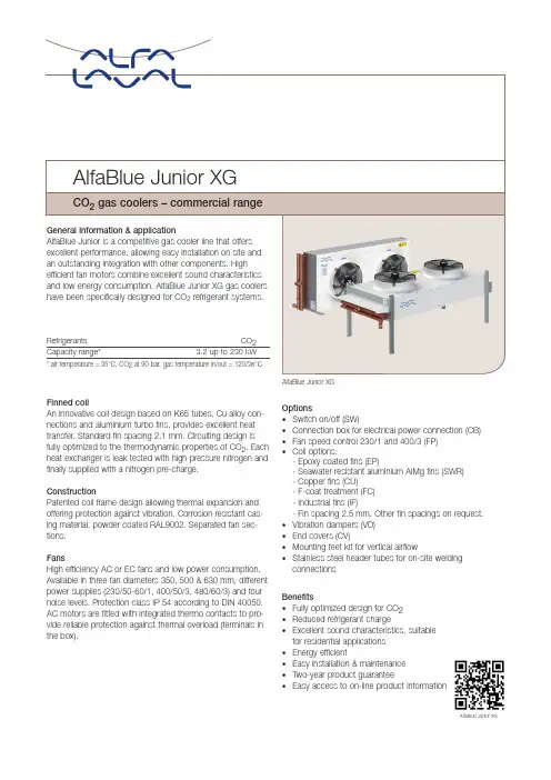
AlfaBlue Junior XGFinned coilAn innovative coil design based on K65 tubes, Cu alloy con-nections and aluminium turbo fins, provides excellent heatt ransfer. Standard fin spacing 2.1 mm. Circuiting design is fully optimized to the thermodynamic properties of CO 2. Each heat exchanger is leak tested with high pressure nitrogen and finally supplied with a nitrogen pre-charge.ConstructionPatented coil frame design allowing thermal expansion and offering protection against vibration. Corrosion resistant cas-ing material, powder coated RAL9002. Separated fan sec-tions.FansHigh efficiency AC or EC fans and low power consumption. Available in three fan diameters 350, 500 & 630 mm, differentpower supplies (230/50-60/1, 400/50/3, 480/60/3) and four noise levels. Protection class IP 54 according to DIN 40050. AC motors are fitted with integrated thermo contacts to pro-vide reliable protection against thermal overload (terminals in the box).AlfaBlue Junior XGOptions• Switch on/off (SW)• Connection box for electrical power connection (CB)• Fan speed control 230/1 and 400/3 (FP)• Coil options:- Epoxy coated fins (EP)- Seawater resistant aluminium AlMg fins (SWR) - Copper fins (CU)- F-coat treatment (FC) - Industrial fins (IF)- Fin spacing 2.5 mm. Other fin spacings on request.• Vibration dampers (VD)• End covers (CV)• Mounting feet kit for vertical airflow• Stainless steel header tubes for on-site welding connections Benefits• Fully optimized design for CO 2• Reduced refrigerant charge• Excellent sound characteristics, suitable for residential applications • Energy efficient• Easy installation & maintenance • Two-year product guarantee• Easy access to on-line product informationHow to contact Alfa LavalUp-to-date Alfa Laval contact details for all countries are always available on our website at AHE00029EN 1902Alfa Laval is a trademark registered and owned by Alfa Laval Corporate AB. Alfa Laval reserves the right to change specification without prior notification.SelectionSelection and pricing is to be performed with our Alfa Laval air heat exchanger selection software. Please contact our sales organization for details and full technical documentation.CertificationsThe Alfa Laval quality system is in accordance with ISO 9001. All products are manufactured according to PED.PackingAll units are packed and shipped in horizontal airflow position. AlfaBlue Junior 351, 352, 353, 501 & 502 units are mounted on a wooden pallet and covered with a sturdy cardboard box. All other models are mounted on a wooden pallet, wrapped with plastic foil and covered with an open crate.Design pressureDesign pressure 120 bar.XGtypeDimensions mm** Full dimensional details in instruction manual & websiteDimensions。
Operation ManualAir Cooled Thermo-con (Compact type)INR-244-831/INR-244-8321 Read Before UsingThank you for purchasing SMC’s Thermo -con (hereinafter referred to as the “product”). This “Operation Manual” (hereinafter referred to as “this manual”) briefly explains the essential safety instruction procedures to start and stop the product and reset its alarms. Read this manual before using.2 Safety InstructionsThis manual contains essential information for the protection of users and others from possible injury and/or equipment damage.• Read this manual before using the product, to ensure correct handling, and read the manuals of related apparatus before use. • Keep this manual in a safe place for future reference.• These instructions indicate the level of potential hazard by label of “Caution”, “Warning” or “Danger”, followed by important safety information which must be carefully followed.• To ensure safety of personnel and equipment the safety instructions in this manual and the product catalogue must be observed, along with other relevant safety practices.•This manual “Warning”, and “Caution” to present warning details in an easy -to-• During operation or maintenance of the product, do not disable the interlock function of any device. Otherwise unexpected personnel injury or damage to the product may occur.• When turning on/off the power observe the procedure. Otherwise unexpected malfunction or danger may occur.• When maintaining, cleaning or in case of emergency, turn off the power source.• After identifying a problem be sure to check the cause and take necessary countermeasures before turning on the power. • The product is operated at high voltage.• The compatibility of equipment is the responsibility of the person who designs the system or decides its specifications.Since the products specified here can be used in various operating conditions, their compatibility with the specific system must be based on specifications or after analysis and/or tests to meet specific requirements. • Only trained personnel should handle or operate the product.Transportation, installation and maintenance of the product can be dangerous and should be done by persons who have full knowledge and experience on the product and system. Cover panels of the product should be opened only by qualified service technicians or qualified personnel. • Do not modify or reconstruct the unit.• Do not service machinery/equipment or attempt to remove components until safety is confirmed.21) Inspection and maintenance of machinery/equipment should only be performed after confirmation of safe locked-out positions.2) When equipment is to be removed, confirm the safety process as mentioned above. Switch off electrical supplies and ensure any high temperature parts have cooled to ambient temperature.3) Before machinery/equipment is re-started, ensure all safety measures are taken so the product and system can be started in a safe manner. 4) Do not use this product outdoor (indoor use).• Do not use this product outside of the specifications. Contact SMC if it is to be used in any of the following conditions.1) Conditions and environments beyond the given specifications.2) Installations in conjunction with atomic energy, railway, air navigation, vehicles, medical equipment, food and beverage, recreation equipment, emergency stop circuits, press applications, or safety equipment.• If abnormal conditions occur, such as abnormal noise or smoke, or water leakage, take the following actions. 1) Shut down power.2) Contact an authorised SMC dealer for repair.• After shutting down the power supply, ensure a time interval at least 3sec between ON and OFF. Restarting the product within that interval may cause it to malfunction.• Do not use devices that generate electromagnetic radiation such as cellular phones near the product. There is a possibility that this can cause the product to malfunction.• This unit has several interlock functions, which activate when a dangerous operation or condition occurs to stop the product and make it safe. This is a function to protect personnel and restrict operation that may cause damage to the product or facility, and to remove dangers related to safety. • When dispose the product, contact an industrial waste disposal company for disposal of the product. To minimize the risk, drain the fluid from the product when it is scrapped. If the fluid is left inside, an accident and damage can result during transportation.• When the circulating fluid temperature is low, do not operate it at a low flow rate. It may freeze circulating fluid in the product when used at low temperature and low flow rate.• This unit does not use parts that meet the SCCR specifications.3 Specifications3.1 General Description and Intended UseThis product uses a built in pump to circulate liquid (water or 20% EG) at a constant temperature, controlled by Thermo-Electric (Peltier) Modules. This circulating fluid cools parts of the customer’s machine that generates heat.3 3.3 Performance ChartsValues on the performance charts are not guaranteed values butrepresentative values. Allow margins for safety when selecting the model3.3.1 Cooling Capacity INR-244-831*Cooling capacity decrease approx. 20W when high pressure pump option selectedINR-244-832*Cooling capacity decrease approx. 20W when high pressure pump option selected3.3.2 Heating Capacity INR-244-831*Heating capacity increase approx. 10W when high pressure pump option selectedINR-244-832*Heating capacity increase approx. 10W when high pressure pump option selected3.3.3 Pump CapacityINR-244-831 / INR-244-832J.S.T. Mfg.3.5 Model number of productThe product can be ordered with the model number configured as shown below.3.6 Product serial number codeThe production serial number code printed on the label indicates the year and month of production as per the following table: HEC-OM-Y008-B4 Special Features•Offset functionThis function controls the temperature slide by an offset value from setpoint temperature. When the circulating fluid travels to the target object,a certain deviation occurs between the temperature just before theobject and the set temperature of the product due to the influence ofambient temperature on the piping. In this case, if the deviation is inputas the offset value, the temperature of the circulating fluid just before theobject can match with the setting value. Internal sensor value for thealarm does not include the offset value. For example, if 0.1 °C is sethere, the actual reference temperature for control is lower than theindicated SV by 0.1 °C.•Setting value memory functionEven if the power is turned off the set values are saved and will berestored at power on.5 Installation5.1 Installation•Pay special attention to the safety of all personnel when installing andtransporting the product.•Do not install the product unless the safety instructions have been readand understood.•Leakage from the product may damage peripheral equipment. Install adrain pan under the product to capture leakage. Furthermore, mountdevices like a leak sensor on the installed drain pan to detect leakage sothat it can alert operators around the area.5.2 Environment•Do not use in an environment where the product is directly exposed towater, oil, corrosive gases, chemicals, salt water or steam.•The product should be installed upright on a stable base.•Do not install the product in a location where the air inlet and air outletvents are blocked. Also do not use the product in a sealed enclosure.•Do not use in an explosive atmosphere.•Do not mount the product in a location where it can be exposed toprolonged sunlight. Use a protective cover.•Do not mount the product in a location where it is subject to strongvibrations and/or shock. Check the product specifications.•Do not use the product where it can be exposed to strong electrical ormagnetic emissions.•Do not mount the product in a location where it is exposed to noisesources (such as discharging equipment, large relay and thyristor).•Do not mount the product in a location with an altitude of more than 2000meters.•Do not mount the product where it is exposed to materials such assilicone, which may generate harmful gas.•Install the product in a location where the ambient temperature range isbetween 10 to 35°C and the relative humidity range is between 35 to70%. No dew condensation is allowed on the unit.•Do not mount the product in a location exposed to radiant heat.5.3 Filter cover and Air filter1. Ensure that the power source and the power supply of the product areturned off (or the power plug must come off).2. Loosen the product screws (2 places). Attach the included filter coverand air filter (hook the protruding part of the filter cover on the product)and tighten screws to the required torque (M3: 0.63Nm).5 Installation Continued5.4 Piping•Ensure that the power source and the power supply of the product isturned off (or the power plug must come off )•Ensure the flow rate of the circulating fluid is as high as possible tomaintain the temperature stability. Therefore, the length of the externalpiping should be minimized and internal diameter should be as large aspossible. Piping must have sufficient strength for the maximumdischarge pressure of the circulating circuit.•Likewise, if a tube is bent or multiple elbow fittings are used, the pipingresistance will increase and the flow rate will decrease. If the flow ratefalls, the temperature stability will decrease.•If installing a tank externally, only a sealed tank should be used. Do notuse an open tank.•Ensure that the INLET and OUTLET for circulating fluid is connectedcorrectly. If any valves are used ensure that they do not restrict the flow,otherwise low flow may cause an alarm.•When installing piping or fittings, ensure sealant material does not enterinside the port. When using seal tape, leave 1.5 to 2 threads exposed onthe end of the pipe/fitting.•Be sure to correctly tighten the fittings to the required torque(Rc1/4:12 to14 N・m).5.5 Wiring•This product may use maximum current of 18A, depending on theoperating conditions. Select the power source with some margins.•Ensure that the power source and the power supply of the product isturned off before connecting the various connectors and power supplycable.•Supply disconnecting device according to IEC60947-3 for the productmust be provided in the end system.•Do not install the disconnecting device in the place where the operationis difficult. And also the switch of the disconnecting device must complywith the direction of the switch specified by IEC60447.•Ensure that a lock out facility is available on the power source. Ensurethat an Earth Leakage Breaker with proper capacity is used. Install itabove 0.6m from the floor.•Use the dedicated power supply for this product with SELV.•Preparation and wiring of power supply cable1) Attach the proper connector (e.g. crimped terminal) that matches thepower source to one end of accessory power supply cable.(Accessory cable: 16AWG, UL1007)2) Connect the connector to the power source, and the product.•Ensure that there is enough space between the power supply cable andthe communication cable of the product and power cables of otherequipment.•Ensure the power supply and ground (protective earth) connections aremade correctly.•Be sure to provide the grounding (16AWG). Do not connect the ground incommon with the ones for equipment that generates strongelectromagnetic noise or high frequency.•Connect the host to this unit with a twisted pair shield cable whenapplying communication function. When using the Communicationconnector, connect the circuit separated from the mains circuit byreinforced insulation.•Ensure that external instruments connecting to this product provide theenclosure complied with UL61010-1 and use the cable which providesflame resistance (over VW-1).5.6 Filling the product1. Ensure that the power source and the power supply of the product areturned off (or the power plug must come off).2. Remove the reservoir cap.3. If using Ethylene Glycol, refer to the suppliers Material Safety Data Sheet(MSDS) and wear Personal Protective Equipment (PPE) as appropriate.4. Fill the circulating fluid into the reservoir. Stop filling once the level offluid reaches the “H” mar k.5. Turn on the power switch to fill the piping with the fluid.6. When the piping is filled with the circulating fluid, the level of thereservoir decreases and low fluid level alarm arises accordingly. Then,turn off the power supply once again.7. Repeat the step from 4 to 6 until alarm doesn’t appear anymore.8. Then, replace the cap on the reservoir and tighten it securely.9. Keep the fluid level between H and L of the level indicator5 Installation Continued•Never touch the power switch with wet hands to avoid electrical shock.•Do not touch the surface when the set temperature is high. Temperatureof the tank and the chassis near the tank could be high.•Fluid other than water or Ethylene Glycol (up to 20%) should not be usedas circulating fluid. Using such fluid may lead to leakage or damage ofthe pump.•Operation of the pump with a large amount of air left in the piping forprolonged period may damage the pump. Remove air from piping beforestarting operation.•If the power switch is turned on without circulating fluid, the pump couldbe damaged.•Take care not to spill water over the product when supplying water to thereservoir. When a spill is made, wipe it off immediately and only supplypower after it has dried. If this procedure is neglected, it may causedamage to the product.•If a fluid with low conductivity such as DI water is used as circulating fluid,it can cause static electricity due to friction and damage the product.Take measures to minimize the static electricity from circulating fluid.•Do not use with flow rate of circulating fluid is zero. If the flow rate is zero,the temperature of circulating fluid cannot be detected and might beincreased or decreased. The pump might be broken as well.6 Operation6.1 Power UpWhen power is turned on, the controller setting number is indicated ondisplay panel for approx. 4 seconds.6.2 OperationThe product begins operation immediately after the power is turned on.The pump, fan and heat exchanger will be running and the product willbegin temperature control.6.3 Details of Controller/DisplayNo. Description Detail①Display1 Displays characters indicating temp. control or setting content.②Display2 Displays set temperature or each selected input value.③[▼] key (DOWN key)Decreases set data.④[▲] key (UP key)Increases set data.⑤[MODE] key Used to change screens and modes.⑥[FUNC] key Used to shift digits of SV⑦Output LEDOUT1: Lights up during heating.OUT2: Lights up during cooling.OUT3,4: Lights up when pump and fan are stopped.⑧Alarm(DI1) LED Lights up Level switch alarm occurs.⑨Alarm(DI2) LED Lights up thermostat alarm occurs.⑩Communication LED Flashes during communication. Normally, it remains on.⑪RDY LED Lights up when temp. control, pump and fan are stopped.6.4 SettingsController has two modes, Operation mode and Setting mode. Each modehas the following contents.6 Operation ContinuedOperation Mode: Initial modeUsed in normal operation (e.g. setting of target temperature/offset.)Setting Mode: Press and hold [MODE] key for 2 seconds.Used at maintenance and initial setting for controller/PID/Communication.•Setting of functions and data in each mode1) Press [MODE] key in each mode to select the required function.2) Increase or decrease data with the [▲] or [▼] key・Each press of the [▲] key increases the data by one count.・Each press of the [▼] key decreases the data by one count.・Holding the [▲] or [▼] key accelerates the increase or decrease.6.4.1 Operation ModeWhen the power supply switch is turned on, the product is in operationmode. The target temperature is shown as well as the current measuredtemperature. Each presses of the [MODE] key changes the operationmode display as follows.No. Modes FunctionSetting range(Min. increment)Default1Target Temp./Measured Temp.Indication and settingSets target temperatureSet with [▲] or [▼] key[INR-244-831]10.0 to 60.0︒C(0.1︒C)[INR-244-832]4.0 to 60.0︒C(0.1︒C)25.0Indicates currenttemperature on PV andtarget temperature on SV2Offset SettingSets the offset value of thePV.Set with [▲] or [▼] key-9.9 to 9.9︒C(0.1︒C) 0Ex. If set to 0.5, thetemperature is controlled toa value that is 0.5o C lowerthan displayed temperature(PV).3Heating outputindicatorIndicate the heating outputratio0.0 to 100.0% -4Cooling outputindicatorIndicate the cooling outputratio0.0 to 100.0% -Operation mode[MODE] keyTarget / Measured Temp. Indication and settingOffset settingHeating output indicatorCooling output indicatorSetting Mode<SET4> [▼][▲] key <SET17>Control setting mode Communication setting mode[MODE] key [MODE] keyControl Mode Communication parameterHeating proportional band Communication speedIntegral time Communication addressDerivative time Response delay timeHeating proportional cycleARWCooling proportional bandCooling proportional cyclePress and hold [MODE] key for 2 secTurn on the powerAir filterScrews formounting filterFilter coverThe protruding part①②③④⑤⑥⑦⑪⑩⑧⑨6.4.2 Setting ModeSetting mode can be shown by pressing and holding the [MODE] key for approx. 2 sec.Pressing the [MODE] key for approx. 2 sec again will return the setting mode to the Operation mode.Setting mode selection is indicated with ”and the required setting mode can be selected by increasing or decreasingthe indicated number with the [▲] or [▼] keySET4: Control Setting ModeSelecting “04” in Setting mode activates the control setting mode.activates the control setting mode. Each presses of the [MODE] key changes the operating mode as follows.Communication address settingResponse delay time setting7 Outline Dimensions (mm)INR-244-831INR-244-83289 Maintenance9.1 Daily Check1) Indication of display panel: Check temperature condition and confirm whether or not an alarm has occurred.2) Confirm that the panel, heat sink and filter are free from dust. A large amount of dust may impair the performance.3) Confirm there is no leakage of circulating fluid and check the condition of the piping (e.g. no tight bends or crushed pipes).4) Confirm there is no abnormal sound, smell or heating from the product.• When cleaning the panel, heat sink, filter use a vacuum cleaner to remove the dust. Do not use water or steam since it leads to rusting of the frame. 9.2 General MaintenanceReplace the circulating fluid regularly to avoid any problems due to algae or contamination.<Drain circulating fluid>1. Drain circulating fluid from the circulating fluid IN port.Loosen the reservoir cap to help draining. (Do not remove the cap)2. To drain from the piping, blow air (0.05MPa, about 1 minute) from the circulating fluid OUT to IN port. Close the reservoir cap while blowing.Clean air filter periodically to avoid declining performance. <Clean air filter>1. Loosen the screws (2 places), open the filter cover and remove thefilter.2. Clean the filter, then put it back to the product.•The repair and maintenance services of this unit are performed only at SMC factory. SMC does not provide on-site repair or maintenance service in a national or overseas situation.• It is recommended to prepare spare units to minimize downtime due to those repair and maintenance services.•Drain the fluid from the product when it is returned for the repair and maintenance service. If the fluid is left inside, an accident and damage can result during transportation.• Do not make any modification to the product.•Do not disassemble the product, unless required by installation instructions.• If fluid other than water is used, wash the circulating fluid circuit with water or DI water before returning the product to SMC. Products that have not been washed may not be accepted at the factory.10 Troubleshooting4-14-1, Sotokanda, Chiyoda-ku, Tokyo 101-0021 JAPAN Tel: + 81 3 5207 8249 Fax: +81 3 5298 5362 URL https://Note: Specifications are subject to change without prior notice and any obligation on the part of the manufacturer. © 2023 SMC Corporation All Rights ReservedGABCHIJKL DEFMScrews for maintenance Filter。
Refrigerators, Refrigerator-Freezers and FreezersExplosion-Proof Flammable Material Storage Cool-Lab,General Purpose35513551-1037503761-13551-13551-113750-137623555355637513762-13555-13556KG3751-13764A35573556-437523764-1A3557-23556-4KG375337703557-43556-63753B3771375437723755375637573761057-196-00•2/22/08Table of ContentsSafety Information (3)Alert Signals (3)Explosion-Proof Refrigerators and Freezers (4)Overview (4)Model3551,3551-1 (5)Model3555,3555-1 (6)Model3557,3557-2,3557-4 (7)Flammable Materials Storage Refrigerators and Freezers (8)Overview (8)Model3551-10,3551-11 (9)Model3556,3556KG (10)Model3556-4,3556-4KG (10)Model3556-6 (10)Cool Lab,General Purpose Laboratory Refrigerators and Freezers (11)Overview (11)Model3570,3570-1 (11)Model3751,3751-1 (11)Model3752 (12)Model3753,3753B (12)Model3754 (13)Model3755 (13)Model3756 (14)Model3757 (14)Model3761,3761-1 (15)Model3762,3762-1 (15)Model3764A,3764-1A (16)Model3770 (17)Model3771 (18)Model3772 (18)Unpacking and Installation (19)Shipping Carton (19)Unpacking (19)Location (19)Clearance (19)Electrical (20)Be Advised (20)Sealing Killark Box Conduit to Help Protect Against Explosions (21)Operation (24)Environmental Operating Conditions (24)Start-Up Procedure (24)Restart Procedure (24)Control Panel Lights(Model3753) (25)How to Save Energy (26)Safety Tips (26)Optional Equipment (27)Optional Buzzer Alarm (27)Troubleshooting (29)Maintenance (30)Cleaning of Units (30)Interior/Exterior and Door Gaskets (30)Condenser (30)Manual Defrost Procedure(Models3556-4,3556-6,3557-2,3557-4,3750,3750-1,3752and3752-1) (31)Manual Defrost Procedure(Model3772only) (32)Reversing the Front Door(Model3551) (33)Reversing the Front Door(Models3556,3557and3751) (34)Reversing the Front Door(Models3772) (35)Replacement Parts (37)Ordering Procedures (38)Warranty (40)2Thank you for selecting Thermo Scientific products for your equipment needs.These instructions contain impor-tant operating and safety information.The user must carefully read and understand these instructions before using the unit.Your unit has been designed to optimize function,reliability,safety and ease of use.It is the userʼs responsibility to install the bath in conformance with local electrical codes.Safety Information3WarningWarnings alert you to a possibility of personal injury.CautionCautions alert you to a possibility of damage to the equipment.NoteNotes alert you to pertinent facts and conditions.Hot SurfaceHot surfaces alert you to a possibility of personal injury if you come in contact with a surface during use or for a period of time after use.Alert SignalsWarningDANGER :RISK OF CHILD ENTRAP-MENT.BEFORE YOU THROW AWAY YOUR OLD REFRIGERATOR OR FREEZER:•TAKE OFF DOORS•LEAVE THE SHELVES IN THE PLACE SO THAT CHILDREN MAY NOT EASILY CLIMBINSIDE.Explosion-Proof Refrigerators and Freezers45MODEL 3551,3551-123-1/2”Wide,Two-door Refrigerator/FreezerFeatures:•Overall 11cu.ft.•Three adjustable shelves •Four door shelves •Hydraulic thermostat•Adjustable natural air-flow vent •Manual defrost •ABS plastic interior •White colorE XPLOSION -P ROOF U NITSsn o i s n e m i D r e b m a h C r e z .l o V l a t o T s n o i s n e m i D r o i r e t x E NOTE:Amps listed are at normal run mode,starting amps may be higher.E XPLOSION-P ROOF U NITSMODEL3555,3555-162”Wide,Chest freezerFeatures:•Overall18cu.ft.•Key lock•Storage basket•Keylock lid•Manual defrost•White colorNOTE:Amps listed are at normal run mode,starting amps may be higher. 6E XPLOSION-P ROOF U NITSFlammable Materials Storage Refrigerators and Freezers8F LAMMABLE M ATERIALS S TORAGE U NITSF LAMMABLE M ATERIALS S TORAGE U NITS11Cool Lab,General-Purpose Laboratory Refrigerators/FreezersMODEL 3750,3750-121.25”Wide,Refrigerator/freezerFeatures:•One-piece seamless interior •Two rustproof,slide-out shelves •Three in-door shelves •Adjustable foot •Drip tray•Manual defrost •White colorNOTE (3750and 3751):THESE UNITS ARE DESIGNED FOR FREE STANDING INSTAL-LATION ONLY .IT MAY BE INSTALLEDUNDER A COUNTER ONLY IF SUFFICIENT SPACE FOR AIRFLOW IS PROVIDED.C OOL L AB G ENERAL -P URPOSE L ABORATORY R EFRIGERATORS /F REEZERSMODEL 375221.25”Wide,Under-counter freezerFeatures:•Adjustable thermostat •Magnetic gasket•Hermetically-sealed compressor •Manual defrost •White colorMODEL 3753,3753B 24”Wide,Under-counter freezerFeatures:•Exterior thermostat•High temperature alarm •Reversible door •3slide out drawers •Key lock •White colorle d o M sn o i s n e m i D r e b m a h C r o t a r e g i r f e R F NOTE:Amps listed are at normal run mode,starting amps may be higher.12C OOL L AB G ENERAL-P URPOSE L ABORATORY R EFRIGERATORS/F REEZERSMODEL3754 24”Wide, Front Venting Refrigerator 0Clearance Front and Sides Features:•Automatic cycle defrost •2adjustable shelves •Built-in or freestanding MODEL3755 24”Wide, Front Venting Freezer 0Clearance Front and Sides Features:•Manual defrost •3shelves •Reversible door •Built-in or freestandingl e d o M s n o i s n e m i D r e b m a h C r o t a r e g i r f e R r FNOTE:Amps listed are at normal run mode,starting amps may be higher.1314C OOL L AB G ENERAL -P URPOSE L ABORATORY R EFRIGERATORS /F REEZERSNOTE:Amps listed are at normal run mode,starting amps may be higher.C OOL L AB G ENERAL-P URPOSE L ABORATORY R EFRIGERATORS/F REEZERSNOTE:Amps listed are at normal run mode,starting amps may be higher.1516C OOL L AB G ENERAL -P URPOSE L ABORATORY R EFRIGERATORS /F REEZERSNOTE:Amps listed are at normal run mode,starting amps may be higher.C OOL L AB G ENERAL-P URPOSE L ABORATORY R EFRIGERATORS/F REEZERS18C OOL L AB G ENERAL -P URPOSE L ABORATORY R EFRIGERATORS /F REEZERSMODEL 377124”Wide,Combination Refrigerator/FreezerFeatures:•4adjustable refrigerator shelves •2adjustable freezer shelves •Automatic defrost •Reversible doors •Key lock•Front mount thermostat•Designed to fit under overhead counters •White colorMODEL 377223.5”Wide,Combination Refrigerator/FreezerFeatures:•4adjustable refrigerator shelves •3fixed freezer shelves•Automatic defrost refrigerator •Manual defrost freezer •Reversible doors•2independent adjustable thermostat •2independent compressors •White colorNOTE:Amps listed are at normal run mode,starting amps may be higher.Unpacking and Installation20I NSTALLATIONCautionDO NOT REMOVE,under any cir-cumstance,the grounding prongs fromthe 3-prong power cord sup-plied with all units.CautionDO NOT USE electrical extension cords that may result in voltage loss and possible hazardousoperation.CautionRisk of electric shock.(For units with B,R27and R30options.)THis equipment has two power supply cords.Unplug all cords before mov-ing or servicing this equipment.WarningExplosion-proof units do not come with line cords.They require rigid conduit to be run directly in order to seal offthe fitting on thermostat housing.This should be done by a licensed electrician and follow all local and electrician and follow all local electrical codes.If any ques-tions pertaining to electrical safety arises,please refer to article 501of the National Electrical Code.I NSTALLATION22I NSTALLATIONFigure 2:Horizontal Conduit,Cutaway•Insert fiber rope material down into horizontal conduit opening.Pressing down firmly,work the material into the right hub and—most importantly—being sure the material COMPLETELY SURROUNDS THE WIRING,from the top to the bottom,completely blocking this end of the horizontal conduit.I NSTALLATION•Pour sealing compound down in between the two fiber rope dams filling the remaining space.Pour slowly, being careful not to trap air bubbles.Immediately wipe off any spilled sealing compound.•Screw conduit domed-cover back onto conduit opening.NOTE:INITIAL SETUP OF SEALING COMPOUND WILL OCCUR IN APPROXIMATELY30MINUTES HOW-EVER,THE SEALING COMPOUND REQUIRES A MINIMUM OF8HOURS ABOVE32ºF TO DEVELOP SUFFICIENT STRENGTH TO WITHSTAND EXPLOSIONS.23Operation241.O PERATION23845673772Control PanelO PERATION2627OptionalEquipment16789231010TEMPERATURE DISPLAY (4):Digital devices generally do not round off a reading.In the case of this temperature monitor,when the displayreports,say a value of 10degrees,that “10”can repre-sent any temperature from 10.0to 10.9degrees.Therefore,a very small change (0.1degree or less),or a minor electronic disturbance many cause the displayed temperature to change one digit.Only when the displayed temperature is changing within a period of 20seconds or greater can the change be related to real thermal changes in the space of time being monitored.READING AND ADJUSTING ALARM POINTS:To read or set alarm points press the Display button (10)under the HIGH (3)or LOW ALARM DISPLAY (9)and while keeping it depressed,turn the adjustment screw(s)located under ADJUST (2,8)slowly to set the desired alarm setpoint.(On dual alarm points,only ONE setting can be adjusted at a time.)NoteThe alarm status lamp (6)will flash rapidly and the audio will sound in short pulses during an adjustment.Optional Buzzer AlarmO PTIONAL E QUIPMENTALARM CONDITIONS:•HIGH SETPOINT ALARM:If the probe tempera-ture exceeds the HIGH setpoint(or falls belowthe LOW setpoint on dual setpoint models),theaudio alarm will sound the red ALARM statuslamp(6)will flash.The unitʼs audio alarm can temporarily besilenced by depressing the DELAY button(7).The alarm is shipped set with a30-minute delay.During the delay period,the alarm will chirpabout every30seconds and the alarm statuslamp(6)to flash during the delay period.If the alarm condition is still present at the endof the preset30-minute delay period,the audioalarm will turn on with full intensity.•LOW TEMPERATURE ALARM(9):This alarm istriggered by the temperature falling below thedesired setpoint.It is important that this lowalarm point be set at a lower temperature thanthe high alarm.RELAY OUTPUT:The relay output consists of a SPDT relay that changesstate with a loss of line power OR the presence of analarm condition.The contacts are rated at30V/1Amp.28Troubleshooting2930MaintenanceWarningDisconnectplug from electrical outlet before attempting any maintenance or repair of this unit.Any internal adjustments or repairs must be performed by a qualified service representative.NoteMake no attempt to service or repair a Thermo Scientific product under warranty before consulting your Thermo Scientific dealer.After the warranty period,such consultation is still advised,especially when the repair may be technically sophisticat-ed or difficult.If assistance is needed beyond what the distributor can pro-vide,please call Customer Service at 800-553-0039.No merchandiseshould be returned directly to the fac-tory without obtaining a ReturnMaterials Authorization (RMA)num-ber from Customer Service.M AINTENANCECautionDo not use any sharp instrument,blade or scraper to remove ice and frost on refrigerator surfacesbecause of the very real danger of puncturing the coolingcoil.CautionDo not use any electrical device to defrost the unit.When frost accumulates to 1/4"or more,the operating efficiency of the unit will beaffected.M AINTENANCECautionDo not use any sharp instrument,blade or scraper to remove ice and frost on refrigerator surfacesbecause of the very real danger of puncturing the cooling coil.CautionDo not use any electrical device to defrost the unit.When frost accumulates to 1/4"or more,the operating efficiency of the unit will be affected.Model 3772Illustrating drip pan positionM AINTENANCEM AINTENANCEM AINTENANCEscrewsthe top hinge while holdingthe opposite side of8.Removeplastic caps on the new middle hinge side.Remove screw and mount lower door and fasten middle hinge9.Remove the door handle by removing mounting screws and remount on opposite side10.Mount the upper door on pivot and fasten the upperhinge on opposite side then tighten screws11.For adjustment of doors,loosen screws and reposi-tion door into place and tighten screws12.Move handle to opposite side of doorM AINTENANCEReplacement PartsTo obtain replacement parts information and pricing,please call the Customer Service Department at1-800-553-0039and have the unitʼs model,serial and codenumbers available.This information is located on dataplates on the rear of the unit.Ordering ProceduresPlease refer to the Specification Plate for the completemodel number,serial number,and series number whenrequesting service,replacement parts or in any corre-spondence concerning this unit.All parts listed herein may be ordered from the ThermoScientific dealer from whom you purchased this unit orcan be obtained promptly from the factory.When serviceor replacement parts are needed we ask that you checkfirst with your dealer.If the dealer cannot handle yourrequest,then contact our Customer Service Departmentat563-556-2241or800-553-0039.Prior to returning any materials,please contact ourCustomer Service Department for a“Return MaterialsAuthorization”number(RMA).Material returned withoutan RMA number will be refused.One Year Limited WarrantyThis Thermo Scientific product is warranted to be free of defects in materials and workmanship for one(1) year from the first to occur of(i)the date the product is sold by the manufacturer or(ii)the date the product is purchased by the original retail customer(the“Commencement Date”).Except as expressly stated above,the MANUFACTURER MAKES NO OTHER WARRANTY,EXPRESSED OR IMPLIED,WITH RESPECT TO THE PRODUCTS AND EXPRESSLY DISCLAIMS ANY AND ALL WARRANTIES,INCLUDING BUT NOT LIMITED TO,WARRANTIES OF DESIGN,MERCHANT ABILITY AND FITNESS FOR A PARTICULAR PURPOSE.An authorized representative of the manufacturer must perform all warranty inspections.In the event of a defect covered by the warranty,we shall,as our sole obligation and exclusive remedy,provide free replace-ment parts to remedy the defective product.In addition,for products sold within the continental United States or Canada,the manufacturer shall provide free labor to repair the products with the replacement parts,but only for a period of ninety(90)days from the Commencement Date.The warranty provided hereunder shall be null and void and without further force or effect if there is any(i) repair made to the product by a party other than the manufacturer or its duly authorized service representa-tive,(ii)misuse(including use inconsistent with written operating instructions for the product),mishandling, contamination,overheating,modification or alteration of the product by any customer or third party or(iii)use of replacement parts that are obtained from a party who is not an authorized dealer of Thermo Scientific prod-ucts.Heating elements,because of their susceptibility to overheating and contamination,must be returned to the factory and if,upon inspection,it is concluded that failure is due to factors other than excessive high tempera-ture or contamination,the manufacturer will provide warranty replacement.As a condition to the return of any product,or any constituent part thereof,to the factory,it shall be sent prepaid and a prior written authorization from the manufacturer assigning a Return Materials Number to the product or part shall be obtained.IN NO EVENT SHALL THE MANUFACTURER BE LIABLE TO ANY PARTY FOR ANY DIRECT,INDIRECT, SPECIAL,INCIDENTAL,OR CONSEQUENTIAL DAMAGES,OR FOR ANY DAMAGES RESULTING FROM LOSS OF USE OR PROFITS,ANTICIPATED OR OTHERWISE,ARISING OUT OF OR IN CONNECTION WITH THE SALE,USE OR PERFORMANCE OF ANY PRODUCTS,WHETHER SUCH CLAIM IS BASED ON CONTRACT,TORT(INCLUDING NEGLIGENCE),ANY THEORY OF STRICT LIABILITY OR REGULATORY ACTION.For the name of the authorized Thermo Scientific product dealer nearest you or any additional information,contact us:2555Kerper Blvd.,Dubuque,Iowa,52004-0797Phone:563-556-2241or1-800-553-0039Fax:563-589-0516E-mail:********************Web:。
Page 1| 2CP5 & 2CP50 SERIESHVAC/Refrigeration Pressure Sensor SPECIFICATIONSFeaturesIntroductionApplications• UL recognized• Ceramic capacitive sensor• Durable, compact, low-cost design• Accurate performance over wide temperatures •Overvoltage and short circuit protectedThe 2CP series is ideal for demanding air conditioning and refrigeration applications where long-term reliability and accuracy is a must. The 2CP series provides proven reliability at a competitive price.Sensata Technologies has been a leading global supplier of pressure sensors and switches for over 50 years. The 2CP has many options, consult the factory to customize a 2CP to meet your application’s needs.• Discharge and suction pressure monitoring • Subcooling and superheat calculations • Compressor oil pressure monitoring • Condenser fan control• Compressor staging and unloading • Electronic expansion valve control•Remote systems diagnostics and trendingPage 2STANDARDSSEAL MATERIALSDIMENSIONAL DRAWINGSRev.02/08/18Page 3CONTACT USSensata Technologies, Inc. (“Sensata”) data sheets are solely intended to assist designers (“Buyers”) who are developing systems that incorporate Sensata products (also referred to herein as “components”). Buyer understands and agrees that Buyer remains responsible for using its independent analysis, evaluation and judgment in designing Buyer’s systems and products. Sensata data sheets have been created using standard laboratory conditions and engineering practices. Sensata has not conducted any testing other than that specifically described in the published documentation for a particular data sheet. Sensata may make corrections, enhancements, improvements and other changes to its data sheets or components without notice.Buyers are authorized to use Sensata data sheets with the Sensata component(s) identified in each particular data sheet. HOWEVER, NO OTHER LICENSE, EXPRESS OR IMPLIED, BY ESTOPPEL OR OTHERWISE TO ANY OTHER SENSATA INTELLECTUAL PROPERTY RIGHT, AND NO LICENSE TO ANY THIRD PARTY TECHNOLOGY OR INTELLECTUAL PROPERTY RIGHT, IS GRANTED HEREIN. SENSATA DATA SHEETS ARE PROVIDED “AS IS”. SENSATA MAKES NO WARRANTIES OR REPRESENTATIONS WITH REGARD TO THE DATA SHEETS OR USE OF THE DATA SHEETS, EXPRESS, IMPLIED OR STATUTORY, INCLUDING ACCURACY OR COMPLETENESS. SENSATA DISCLAIMS ANY WARRANTY OF TITLE AND ANY IMPLIED WARRANTIES OF MERCHANTABILITY, FITNESS FOR A PARTICULAR PURPOSE, QUIET ENJOYMENT, QUIET POSSESSION, AND NON-INFRINGEMENT OF ANY THIRD PARTY INTELLECTUAL PROPERTY RIGHTS WITH REGARD TO SENSATA DATA SHEETS OR USE THEREOF.All products are sold subject to Sensata’s terms and conditions of sale supplied at SENSATA ASSUMES NO LIABILITY FOR APPLICATIONS ASSISTANCE OR THE DESIGN OF BUYERS’ PRODUCTS. BUYER ACKNOWLEDGES AND AGREES THAT IT IS SOLELY RESPONSIBLE FOR COMPLIANCE WITH ALL LEGAL, REGULATORY AND SAFETY-RELATED REQUIREMENTS CONCERNING ITS PRODUCTS, AND ANY USE OF SENSATA COMPONENTS IN ITS APPLICATIONS, NOTWITHSTANDING ANY APPLICATIONS-RELATED INFORMATION OR SUPPORT THAT MAY BE PROVIDED BY SENSATA.Mailing Address: Sensata Technologies, Inc., 529 Pleasant Street, Attleboro, MA 02703, USA.Americas+1 (800) 350 2727***************************************Europe, Middle East & Africa +359 (2) 809 1826****************************Asia Pacific*************************.com China +86 (21) 2306 1500Japan +81 (45) 277 7117Korea +82 (31) 601 2004India +91 (80) 67920890Rest of Asia +886 (2) 27602006 ext 2808ORDERING OPTIONSAGENCY APPROVALS & CERTIFICATIONSFrom 0-15 psi (0015) to 0-750 psi (0750)From 0-1 bar (M001) to 0-50 bar (M050)UL recognized file #SA995RoHS, REACH available。
冷冻机说明书一、机器运输(1)冷水机运输移动时应做好必要的防护措施,防雨防撞。
(2)机器在搬运过程中,装卸车时要小心轻放,避免碰击。
二、机器安装(1)机器应安装在通风良好、干燥、无空气污染,环境温度不得高于45℃的室内,安装位置要平衡。
(2)冷水机的进出水管,循环冷却水管,要匹配正确,设计合理,设计合理连接不渗漏。
(3)制冷机组距周围墙壁阻碍物不得小于45CM。
三、电源连接(1)本机采用三相四线,电源线、(R,S,T)接380V电源火线(N)接零线,及注意接正确连接“接地线”。
(2)机组主电源:电源电压:380V±10%电频频率:50HZ±2%(3)电源电压波动超范围时,不能开动机器,如强制开启机器给机器带来损坏的,本公司不承担责任。
(4)机器内的控制连锁线路,电器等不得随意改动,如确应客户需要改动的,应于本公司联系,等到本公司查阅改动线路内容核实后再通知客户,否则本公司不承担改动后带来的后果。
四、机器运行(1)开机前仔细检查四周是否有异常,电线是否正确连接,紧固水管,安装是否正确,电压是否正常。
(2)打开自动补水阀门,查看冷水机的水箱是否已注满水(水冷式的还要查看冷却塔、水泵、水冷凝器等到外循环系统内加满水切勿无水或缺水运行)。
(3)打开电源开关,观看面板上的指示灯,及温度计显示,此时水泵已经工作,而温度计上的小点还在闪烁,主机要等延时4分钟再启动。
五、温度调节操作指南温度计上的指示灯从上到下排列的功能含义如下表:怎样设置温度上下限?同时按上下两个键,进入温度上限设置状态,这时数码显示器上显示的温度即为上限温度(“▲”键增0.1℃“▼”键减0.1℃,按住不放超过0.5秒则快速减)。
温度上限设置完成后、再同时按上下键才能保存数据。
可按同样方法设置温度下限。
注意控制器保证“上限>下限”这一规则。
注意:1、在设置状态,如果连接5秒没有按键,自动退出设置状态。
2、心须退出设置状态才能确保将设定值保存起来。
Ice-O-Matic11100 East 45th AveDenver, Colorado 8023914-1025-A SERVICE PARTS MANUALICE UNDERCOUNTER SERIES CUBERSMODEL-ICEU070ADate 10/9/15This is the list of service parts for the ICEU070Aundercounter ice machine.When ordering a part,be sure to confirm that thepart is for the correct model.Table of Contents Cabinet··············································Page2 Refrigeration System·······································Page3 Water System···········································Page4 Control System··········································Page5 Wiring Diagram··········································Page6Cabinet ItemPart NumberNumber Description 11011411-01Unit Base 21011411-02Insulated Storage Bin 31011411-03Curtain Bracket Right 41011411-04Curtain Bracket Left 51011411-05Curtain Bracket Upper 61011411-06Thumb Screw 71011411-07Curtain assy 81011411-08Plastic Plug 91011411-09Spring 101011337-17Bulb Holder 111011411-10Shock Absorber 121011337-03Evaporator Cover 131011411-11Panel,Left Side 141011411-12Panel,Right Side 151011411-13Panel,Rear 161011411-14Bracket Not Shown 9051127-02 Ice Scoop171011411-15Insulated Top Panel 191011411-16Thumb Screw 201011411-17Front Liner 211011411-18Front Plate 221011411-19Corner Protection Left 231011411-20Corner Protection Right 241011411-21Bracket,Front 251011411-22Panel,Front 261011411-23Logo,Ice-O-matic 271011411-24Front Switch Plastic Protection 281011411-25Air Filter Seat 291011411-26Slide,Air Filter 301011411-27Air Filter 311011411-28Bin Door 321011337-07Bushing 331011411-29Legs KitRefrigeration SystemItemPart NumberNumber Description 11011411-30Compressor (Embraco)21011411-31Start Capacitor(Embraco)3 *1011411-68 Overload (Embraco)4 *Includes 3 & 4 Rel ay (Embraco)51011411-34Valve Body 61011411-35Valve Core 71011411-36Cap 81011357-42Fan Motor (1011411-37 NLA)8a1011411-38Fan Blade 91011337-48Condenser 111011337-49Filter 121011337-58Mechanical Filter131011337-56Hot Gas Valve Body 13a 1011337-57Coil 141011411-39Evaporator assy 151011411-40Suction Line assy Includes Cap Tube and Accumulator 221011337-46Metal Clip 231011411-41Bulb Holder The Cubigel Compressor and Starting Components are No Longer Available.Item PartNumber Number Description 11011337-28Water Inlet Valve1a1011411-42Flow Control 21011411-43Tube,per meter 31011411-44Water Inlet Elbow assy 41011411-45O Ring51011411-46Metal Bracket 61011337-31Water Pump 71011411-47Tube81011411-48Spray System Assy 91011411-49Plastic Plug 101011411-50Plastic Plug 111011411-51Spray Cover Kit 121011337-38Tee Tube 131011337-42Plastic Nut 141011337-39Tube 151011411-52Tube161011411-53Bin Drain 171011337-34O Ring 181011337-32Drain Filter 191011411-54Spray System Seat 201011411-55O RingNot Shown211011411-64Water Inlet Adapter 221011411-65Water Inlet AdapterO RingItemPart NumberNumber Description 11011411-56Warning Light -Reset Button 21011411-57Master Lighted Switch 31011411-58Switch 41011337-64Terminal Board 51011411-59Bin Thermostat 61011337-68Evap.Thermostat 71011411-60Cover 81011411-61Metal Control box 91011411-62PC Board -Cleaning Remind 101011411-63Condenser Sensor Black Plug 11 1011411-70 Condenser Sensor White Plug, From 2012 Serial Number12345678910Wiring Diagram。
冷冻机使用、维修规范本规范是用于公司内活塞式及螺杆式冷冻机冷冻机的使用:一、1.车间冷冻机安装使用前要首先建立设备档案卡(车间、设备科)悬挂设备包保卡。
2.冷冻机属大型设备,使用者与维修人员必须经过严格的岗前培训、考试合格并持证上岗,3.严格按照“四懂三会”的要求对操作工和维修人员进行定期学习培训和现场指导,让其知道应急情况下的处理措施以及故障隐患的现场分析与判断。
每年不小于4学时。
二、冷冻机的规格与使用参数:冷冻机的性能参数主要包括制冷量、进气压力、排气压力、进气温度、排气温度、电机转速、电流、电压等(详见说明书)。
冷冻机必须在说明书规定的性能范围内使用,任何一项参数不在规定的范围之内时都应当对系统和设备本身进行严格检查,直到达到正常使用条件为止。
三、冷冻机的日常管理规定:1.车间操作工时刻注意冷冻机的运行状况,运行中有无异响、杂音等不正常现象,介质泄漏量是否正常。
冷冻机的点检内容主要有:振动是否正常及各部位连接螺栓是否紧固、冷冻机的回油量是否符合要求、循环冷却水是否达到工艺要求、通过视镜观察油位是否在规定范围内及油质是否正常、根据仪表盘读数准确记录电机电流、电压、油温、油压、进气温度、进气压力、排气温度、排气压力等工艺参数,并以此判断冷冻机运行状况及运行缺陷。
2.保全工、机电人员每天定时对冷冻机进行巡检,除1包括的各项巡检内容外,及时处理能够在开车时解决的运行缺陷。
机电人员巡检电气设备并用测温仪测量电机运行温度,判断电机的运行状况。
3.车间操作工要坚守岗位,冷冻机必须由操作工亲自操作或在操作工的监督下由别人代操作,非经主任以上人员允许,任何人严禁私自操作,操作工必须全程掌控设备的操作过程。
四、交接班内容及规定:1.冷冻机的运行状况、参数变化、停机时间及原因。
2. 相关人员及上级领导提示的关于运行设备的注意事项及防范措施。
3.故障处理时间、原因、处理人及处理后存在遗留问题。
4.原有设备缺陷变化及发展。