华硕主板Z87-K说明书
- 格式:pdf
- 大小:3.46 MB
- 文档页数:78
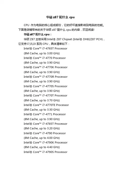
华硕z87配什么cpuCPU作为电脑的核心组成部份,它的好坏直接影响到电脑的性能。
下面是店铺带来的关于华硕z87配什么cpu的内容,欢迎阅读!华硕z87配什么cpu:华硕Z87主板采用Intel® Z87 Chipset (Intel® DH82Z87 PCH),它支持I7,I5,I3系列CPU,具体清单如下:Intel® Core™ i7-4765T Processor(8M Cache, up to 3.00 GHz)Intel® Core™ i7-4770 Processor(8M Cache, up to 3.90 GHz)Intel® Core™ i7-4770K Processor(8M Cache, up to 3.90 GHz)Intel® Core™ i7-4770R Processor(6M Cache, up to 3.90 GHz)Intel® Core™ i7-4770S Processor(8M Cache, up to 3.90 GHz)Intel® Core™ i7-4770T Processor(8M Cache, up to 3.70 GHz)Intel® Core™ i7-4770TE Processor(8M Cache, up to 3.30 GHz)Intel® Core™ i7-4771 Processor(8M Cache, up to 3.90 GHz)Intel® Core™ i7-4785T Processor(8M Cache, up to 3.20 GHz)Intel® Core™ i7-4790 Processor(8M Cache, up to 4.00 GHz)Intel® Core™ i7-4790K Processor(8M Cache, up to 4.40 GHz)Intel® Core™ i7-4790S ProcessorIntel® Core™ i7-4790T Processor (8M Cache, up to 3.90 GHz)Intel® Core™ i5-4670 Processor (6M Cache, up to 3.80 GHz)Intel® Core™ i5-4670K Processor (6M Cache, up to 3.80 GHz)Intel® Core™ i5-4670R Processor (4M Cache, up to 3.70 GHz)Intel® Core™ i5-4670S Processor (6M Cache, up to 3.80 GHz)Intel® Core™ i5-4670T Processor (6M Cache, up to 3.30 GHz)Intel® Core™ i5-4690 Processor (6M Cache, up to 3.90 GHz)Intel® Core™ i5-4690K Processor (6M Cache, up to 3.90 GHz)Intel® Core™ i5-4690S Processor (6M Cache, up to 3.90 GHz)Intel® Core™ i5-4690T Processor (6M Cache, up to 3.50 GHz)Intel® Core™ i5-4570 Processor (6M Cache, up to 3.60 GHz)Intel® Core™ i5-4570R Processor (4M Cache, up to 3.20 GHz)Intel® Core™ i5-4570S Processor (6M Cache, up to 3.60 GHz)Intel® Core™ i5-4570T Processor (4M Cache, up to 3.60 GHz)Intel® Core™ i5-4570TE ProcessorIntel® Core™ i5-4590 Processor (6M Cache, up to 3.70 GHz)Intel® Core™ i5-4590S Processor (6M Cache, up to 3.70 GHz)Intel® Core™ i5-4590T Processor (6M Cache, up to 3.00 GHz)Intel® Core™ i5-4460T Processor (6M Cache, up to 2.70 GHz)Intel® Core™ i5-4460S Processor (6M Cache, up to 3.40 GHz)Intel® Core™ i5-4460 Processor (6M Cache, up to 3.40 GHz)Intel® Core™ i5-4440S Processor (6M Cache, up to 3.30 GHz)Intel® Core™ i5-4440 Processor (6M Cache, up to 3.30 GHz)Intel® Core™ i5-4430S Processor (6M Cache, up to 3.20 GHz)Intel® Core™ i5-4430 Processor (6M Cache, up to 3.20 GHz)Intel® Core™ i3-4330 Processor (4M Cache, 3.50 GHz)Intel® Core™ i3-4330T Processor (4M Cache, 3.00 GHz)Intel® Core™ i3-4330TE Processor (4M Cache, 2.40 GHz)Intel® Core™ i3-4340 Processor (4M Cache, 3.60 GHz)Intel® Core™ i3-4340TE ProcessorIntel® Core™ i3-4350 Processor (4M Cache, 3.60 GHz)Intel® Core™ i3-4350T Processor (4M Cache, 3.10 GHz)Intel® Core™ i3-4360 Processor (4M Cache, 3.70 GHz)Intel® Core™ i3-4360T Processor (4M Cache, 3.20 GHz)Intel® Core™ i3-4370 Processor (4M Cache, 3.80 GHz)Intel® Core™ i3-4370T Processor (4M Cache, 3.30 GHz)Intel® Core™ i3-4170T Processor (3M Cache, 3.20 GHz)Intel® Core™ i3-4170 Processor (3M Cache, 3.70 GHz)Intel® Core™ i3-4160T Processor (3M Cache, 3.10 GHz)Intel® Core™ i3-4160 Processor (3M Cache, 3.60 GHz)Intel® Core™ i3-4150T Processor (3M Cache, 3.00 GHz)Intel® Core™ i3-4150 Processor (3M Cache, 3.50 GHz)Intel® Core™ i3-4130T Processor (3M Cache, 2.90 GHz)Intel® Core™ i3-4130 Processor (3M Cache, 3.40 GHz)Intel® Pentium® Processor G3470Intel® Pentium® Processor G3460T (3M Cache, 3.00 GHz)Intel® Pentium® Processor G3460 (3M Cache, 3.50 GHz)Intel® Pentium® Processor G3450T (3M Cache, 2.90 GHz)Intel® Pentium® Processor G3450 (3M Cache, 3.40 GHz)Intel® Pentium® Processor G3440T (3M Cache, 2.80 GHz)Intel® Pentium® Processor G3440 (3M Cache, 3.30 GHz)Intel® Pentium® Processor G3430 (3M Cache, 3.30 GHz)Intel® Pentium® Processor G3420T (3M Cache, 2.70 GHz)Intel® Pentium® Processor G3420 (3M Cache, 3.20 GHz)Intel® Pentium® Processor G3320TE (3M Cache, 2.30 GHz)Intel® Pentium® Processor G3260T (3M Cache, 2.90 GHz)Intel® Pentium® Process or G3260 (3M Cache, 3.30 GHz)Intel® Pentium® Processor G3258 (3M Cache, 3.20 GHz)Intel® Pentium® Processor G3250T (3M Cache, 2.80 GHz)Intel® Pentium® Processor G3250Intel® Pentium® Processor G3240T(3M Cache, 2.70 GHz)Intel® Pentium® Processor G3240(3M Cache, 3.10 GHz)Intel® Pentium® Processor G3220T(3M Cache, 2.60 GHz)Intel® Pentium® Processor G3220(3M Cache, 3.00 GHz)Intel® Celeron® Processor G1850(2M Cache, 2.90 GHz)Intel® Celeron® Processor G1840T(2M Cache, 2.50 GHz)Intel® Celeron® Processor G1840(2M Cache, 2.80 GHz)Intel® Celeron® Processor G1830(2M Cache, 2.80 GHz)Intel® Celeron® Processor G1820TE(2M Cache, 2.20 GHz)Intel® Celeron® Processor G1820T(2M Cache, 2.40 GHz)Intel® Celeron® Processor G1820(2M Cache, 2.70 GHz)相关阅读推荐:CPU依靠指令来自计算和控制系统,每款CPU在设计时就规定了一系列与其硬件电路相配合的指令系统。

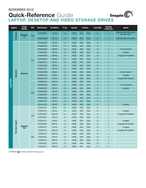
NOVEMBER 2012Quick-Refere nce GuideLAPTOP, DESKTO P AND VIDEO STORAGE DRIVESSeagate Partner Program MembersVisit the Sales Tools section to access the latestproduct roadmap, end-of-life schedule and product information. DistributorsEMEA SPP Support00-800-6890-8282US Sales Support1-800-SEAGATE or 1-405-324-4700Visit for more information or call 1-800-SEAGATE (1-800-732-4283) © 2012 Seagate Technology LLC. All rights reserved. Printed in USA. Seagate, Seagate Technology and the Wave logo are registered trademarks ofSeagate Technology LLC in the United States and/or other countries. Barracuda, FAST Factor, G-Force Protection, Pipeline, SmartAlign, SV35 Series and Momentus are either trademarks or registered trademarks of Seagate Technology LLC or one of its affiliated com-panies in the United States and/or other countries. The FIPS logo is a certification mark of NIST, which does not imply product endorsement by NIST, the U.S., or Canadian governments. All other trademarks or registered trademarks are the property of their respective owners. When referring to drive capacity, one gigabyte, or GB, equals one billion bytes and one terabyte, or TB, equals one trillion bytes. Your computer’s operating system may use a different standard of measurement and report a lower capacity. In addition, some of the listed capacity is used for formatting and other functions, and thus will not be available for data storage. Actual data rates may vary depending on operating environment and other factors. The export or re-export of hardware or software containing encryption may be regulated by the U.S. Department of Commerce, Bureau of Industry and Security (for more information, visit ). Seagate reserves the right to change, without notice, product offerings or specifications. QR502.13-1211US, November 2012NOVEMBER 2012Quick-Reference GuideLAPTOP, DESKTOP AND VIDEO STORAGE DRIVESNew Seagate Model Number KeyDesktop, laptop and video storageST 500 DX 001BRANDCAPACITYSEGMENTATTRIBUTES2 letters ST= Seagate MX= Maxtor2 to 4 digits 80 = 80GB 500 = 500GB 1500 = 1500GB Capacities >9999GB: 10 = 10TB 15 = 15TB2 lettersDX = Desktop Premium DM = Mainstream DL = Entry LevelLX = Laptop Premium LM = Laptop Mainstream LT = Laptop Thin VX = Surveillance VM = DVR VT = DVR Thin3 digits, non-intelligent Varies for:Z-heights Form Factor RPM Cache Interface SED, FIPS Drop Sensor Interface SpeedView a brief training presentation on how our model number format has changed at /seagate/ModelNumber 1 One gigabyte, or GB, equals one billion bytes and one terabyte, or TB, equals one trillion bytes when referring to hard drive capacity.2 See FIPS 140-2 Level 2 Certificate at /groups/STM/cmvp/documents/140-1/1401vend.htm.3 7mm z-height expanded to 9.5mm enables compatibility with standard laptop chassis.4 Advanced Format 4K sector drive with SmartAlign™ technology resolves misalignment conditions.5 Seagate ships this drive in both 4K- and 512-byte sectors. SmartAlign technology is included on 4K sector drives. Both drives are functionally and physically equivalent.。
华硕z790p说明书
华硕Z790P是一款主板,以下为其简要说明书:
1. 主板型号:华硕Z790P
2. 支持处理器类型:Intel LGA1151 第9/8 代 Core 处理器
3. 内存插槽:4个 DDR4 DIMM 插槽,支持双通道技术,最高支持64GB内存
4. 扩展插槽:3个PCI-Express 3.0 x16插槽、3个PCI-Express 3.0 x1插槽
5. 存储接口:6个SATA 6Gb/s接口,1个M.2接口
6. 后部扩展接口:1个USB 3.1 Type-C接口,1个USB 3.1 Type-A接口,4个USB3.0接口,2个USB 2.0接口,1个HDMI接口,1个DisplayPort接口,1个RJ45网口等
7. 网络功能:内置千兆以太网控制器,支持LAN保护、ROG GameFirst IV等技术
8. 音频功能:8通道高清音频,内置SupremeFX音效,以及ROG Sonic Studio III等技术
9. 散热技术:内置ROG散热模块,多达8个4针风扇接口,支持水冷散热系统
10. 游戏特色功能:支持ROG GameFirst IV网络优化、ROG Overwolf游戏助手、ROG Aura Sync 灯效等功能
此说明书只是提供主要规格和功能的概述,详细使用方法和操作指南请参考华硕官方网站提供的完整用户手册。

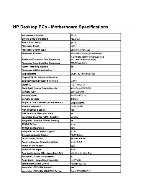
HP Desktop PCs - Motherboard SpecificationsMotherboard Supplier ASUSSystem BIOS Core Brand Asus/AMIBoard Form Factor uATXProcessor Brand AMDProcessor Socket Type Socket-A (PGA462)Processor Families AthlonXP (Thoroughbred,Barton),Maximum Processor Core Frequency <=2.16Ghz (2700+) Thoroughbred <=2.2GHz Barton (3200+)Processor Front Side Bus Frequency 266/333/400MHzHyper Threading Support naProcessor VRM SpecificationChipset Name Crush18D (nForce2 400) Chipset "North Bridge" & RevisionChipset "South Bridge" & Revision MCP2Super I/O ITE IT8712F-AFlash BIOS Device Type & Density 4Mb Flash EEPROM Memory Type DDR SDRAMMemory Speed PC2700/PC2100 Memory Sockets 2 DIMMSingle or Dual Channel System Memory Single channel Maximum Memory Up to 2.0GBAGP Graphics Support YesAGP Graphics Maximum Mode naIntegrated Graphics (UMA) Supplier Up onlyIntegrated Graphics Shared Memory naTV-Out Device noneTV-Out Configuration noneIntegrated AC'97 Audio Support none5.1 channel Audio Support AC'97 DownAC'97 Codec Device Realtek ALC650 Passive Speaker Output (amplified) M,LI,LO,SOAudio SP-DIF Output noneAudio SP-DIF Input noneRear Audio Jacks (Mic,Line-In,Line-Out) Mic, Line-In, Line-Out Internal CD-Audio In Connector 2Front Audio Line-In/Headphone/Mic LI/HP/MICEthernet MAC/PHY Device Realtek 8201BL Integrated IEEE-1394 Support YesIntegrated IEEE-1394 MAC/PHY Device Agere FW802C-PHYOnboard 1394 Maximum Transfer Rate (Mbps)400MbpsIEEE-1394 Ports (Total) 2IEEE-1394 Front Ports (on pin header) 1IDE/ATAPI UDMA Modes ATA-100/66/33Expansion Slots (AGP/PCI) 1 AGP, 3 PCIUSB Interface Specification (2.0/1.1) USB 2.0USB Ports (Total) 6USB Front Ports (on pin headers) 2USB Rear Ports (at rear I/O area) 4Serial, Parallel, Floppy, PS2 Kbd &Mouse Ports1S, 1P, 1F, PS2 K+MFan Headers (CPU, System, Chipset) CPU, System1CPU Fan Speed Control (for active fansink) YesSystem Fan Speed Control YesSuffix (Legend Below) -UL6EUGraphics card (up, not on motherboard) LLAN on motherboard (ethernet)E1394 on motherboardCopyright Hewlett-Packard Co. 1994-2003This information is subject to change without notice andis provided "as is" with no warranty.Hewlett-Packard shall not be liable for any direct,indirect, special, incidental or consequential damagesin connection with the use of this material.。

Important NoticesImproper handling of a vehicle , especially while raised and supported by jack stands, ramps or other mechanical means, can cause serious bodily injury or even death. It is strongly rec-ommended that a trained, experienced mechanic, with proper equipment, do the installation.The seller nor the manufacturer assumes no liability, expressed or implied, for the improper installation or use of this product or its components. Before using, the user shall determine the suitability of the products for it’s intended use. The user assume all responsibility and risk in connection there within.It is the buyer’s responsibility to have all suspension, drivetrain, steering, and other compo-nents checked for proper tightness and torque after the fi rst 100 miles and every 3,000 miles by a qualifi ed professional mechanic.Extreme care should be taken while operating your vehicle to prevent vehicle rollover or loss of control. Both can result in serious injury or death. Do not add or modify parts to this kit or use outside it’s intended purpose. Follow all safety regulations and warnings per state and federal laws.Note: Final fi tment of the wheel to caliper is the responsibility of the customer.Note: It is important to read and understand this ENTIRE installation manual, before starting the installation.Kit Contents1 Pair of calipers w/pads2 Rotors2 Retaining plate2 Preload spacers (C-clip applications)4 Caliper bolts8 T-bolts8 Nuts2 Disc brake mounting plate assembly (1 Left and 1 Right)1 stainless steel brake line kitTools and Equipment That May Be RequiredDifferent models and years of vehicle use different-sized fasteners, and every effort has been taken to correctly identify the proper sized tool for each step of the installation. Occasionally, however, manufacturers use alternate fasteners, so it’s advisable to check that each tool cor-rectly fi ts the fastener before loosening or tightening it. The following tools and equipment may be needed:9/16” socket wrench12mm socket14mm wrenchTorque wrenches capable of 10-148 lb-ft settingsSeveral ragsSmall funnel or suitable means of fi lling master cylinder reservoirBrake bleed bottle1 pair of jack stands or other means of supporting vehicleHydraulic pressPair of PliersStep 1-Remove WheelsWARNING - Brake fl uid will damage most painted surfaces. Immediately clean spilled brake fl uid from any painted surfaces. Be sure the cap is securely installed on the master cylinder. If the cap is loose or removed, it is likely more fl uid willdrip.Note: All Photographs Show Left Side Installation, unless noted otherwise.Break loose the lug nuts on both rear wheels before jacking up the car.Refer to the Owners Manual for the correct location when jacking up the vehicle. Jack up the vehicle and secure on a pair of jack stands. Never leave any vehicle supported with only a jack - always use jack-stands.After securing the vehicle at a convenient height, remove the rear wheels.Note: If you remove the bottom lug nut last while holding the bottom of the tire, it will lessen the chances of the wheel tilting on it’s own and make removal easier.Step 2 -Removal of Drum Brakes and AxleRemove brake drums from thebrake assembly.Remove the hard line from thewheel cylinder attached to thebacking plate.For c-clip applications- Removethe differential cover, unbolt thecross shaft and remove it from thevehicle. See factory service manualfor additional information.Using a 9/16” socket, remove thefour nuts that hold each axle shaftinto the axle and remove the axleshafts from the axle. Some leakagemay occur.Remove the backing plate from theaxle housing.Wipe clean grease and contami-nants from all surfaces.For semi-fl oat applications- Pressthe old bearings and seals fromthe axle shafts. C-clip applicationsdo not need the removal of the oldbearings and seals unless parts areneeded to be replaced.Install the disc brake mounting plate onto the axle flange with new supplied retaining bolts. The mounting plate is directional, insurethat the plate is installed on the correct side.Step 3 -Install Disc Mounting PlateIn order to install this kit, remove the factory bolts from the axle fl ange. If installing on a C-clip application do not remove the fac-tory bolts.Install the supplied bolts (longer than factory bolts) in the axle fl ange.Adjust the internal parking brake shoes with the adjuster until there is just enough room to slide the ro-tor over the shoes. Refer to the fac-tory service manual for additional information.STEP 4 -Install Axle ShaftsApply grease to the outside of the bearing seal assembly and slide the preload spacer onto the seal. The grease will help hold the spacer in place.Slide the axle shaft into the axle housing by hand, lining it up with the differential. The axle shaft should not be forced, damage mayoccur.On C-clip retained axles, slide the axles all the way into the axle hous-ing using care to avoid damage to the splines or the bearing surface. Reinstall the C-clip and the cross shaft. Ensure that all old silicone is cleaned from the differential hous-ing and the differential cover, and reinstall the differential cover using a new gasket or silicone. Fill thehousing with new oil.Using a hydraulic press, press the new bearing and retaining collar onto the axle shaft. Refer to the factory service manual for more details.Grease the shaft where the axle shaft seal will be installed, theninstall the seal.Install the retaining plate and new preload spacer on axle shaft. Notice the direction the preload spacer is facing in the photo to the right. The chamfer side faces inboard.STEP 5 -Install the Rotor and CaliperInstall the rotor on the axle.Install the brake pads in the caliper.Using a 12mm socket wrench in-stall the caliper onto the mounting plate. Torque the bolts to 15-18 ft-lbs.Line up the access holes located on the axle shafts with the retainer bolts. Using a 9/16” socket wrench tighten the four nuts to 25 - 30 ft-lbs.STEP 4 -(Continued)Install Axle ShaftsSTEP 6 -Install Stainless Steel Brake LinesInstall the caliper end of the stainless steel brake line by fi rst placing a copper crush washer on either side of the banjo fi tting.Insert the banjo bolt into the caliper using a 14mm wrench or socket to tighten it. Insert the stainless steel brake line fi tting through the chassis bracket, and screw it onto the hard line fi tting by hand a few turns, to ensure that it is properly engaged. Tighten the hard line fi tting.Check to ensure that the brake line is not binding in any way, nor interfering with any suspension component.Note that you will need to purchase shorter metal brake lines from an automotive pats supplier.If the brake line is not properly routed, a catastrophic failure could occur. If you are unsure that the line is routed properly and safely, do not drive the car. Please call our Tech Support Dept. for assistance if you have any doubt as to the brake line routing.Install the emergency brake cable at the mounting plate and adjust, refer to the factory service manual.If realignment is necessary, loosen the banjo bolt, and realign the brake line, or loosen the inboard end of the line, and slightly re-clock the fitting.Weld the brake line mounting tab onto the axle tube. Install the brake line through the tab and install the c-clip to secure the line.STEP 7-Bleed BrakesComplete installation on both sides of the vehicle before bleeding the system. Note: The calipers and lines will need to fi ll with fl uid, quickly draining the master cylinder reservoir. Keep a close watch on the fl uid level when initially bleeding the system. Do not allow the master cylinder reservoir to run dry and draw in air. Doing so may require the brake system to be serviced by a certifi ed brake technician.Refer to owners manual for torque used on bleed screws.After initially bleeding the system, gently tap the caliper body with a non-marring mallet or hammer to dislodge any small air bubbles and re-bleed.After bleeding, apply a constant pressure to the brake pedal and check all connections, including bleed screws, and both ends of the line for leaks.Brake fl uid will damage most painted surfaces. Immediately clean spilled brake fl uid from any painted surface, including the caliper. Though caliper paint is designed to resist harsh chemicals, prolonged exposure will damage the fi nish.STEP 8-Reinstall wheelsCheck wheel to caliper clearance before installing wheels!Reinstall the wheels and torque the lug nuts to your wheel manufacturer’s specifi cations. It may be necessary to snug the bolts before lowering the vehicle and then torque the wheels when the car is on the ground. Alternatively, an assistant may depress the brake pedal while you tighten the wheel nuts to the proper torque setting.Carefully test-drive the vehicle in a safe area at low speed to insure all components are working correctly.。
1、启动阶段1)红灯每2秒闪一次,且伴为“哔-,哔-”警示音:电调未检测到油门信号。
2)绿灯闪烁N次:上电时自动进行锂电节数检测,闪烁N次表示当前锂电为N节。
2、行驶阶段1)油门摇杆处于中点区域,红色和绿色LED均熄灭。
2)前进时,红色LED恒亮;当油门处于正向最大(100%油门)时,绿色LED也会点亮。
3)倒退时,红色LED恒亮。
3、相关保护功能触发时,LED状态含义:1)红灯持续闪烁(单闪,“☆,☆,☆”方式闪烁):电池电压太低,电调进入电池低压保护状态。
2)绿灯持续闪烁(单闪,“☆,☆,☆”方式闪烁):电调温度过高,电调进入过热保护状态。
故障现象解决方法可能原因1、电池电压没有输入到电调;1、检查电池与电调是否连接可靠,如有焊接不良,请重新焊好;上电后电机无鸣音,指示灯也未闪亮06编程设定说明08电调状态指示灯(LED)说明09保护功能说明10故障快速处理01声明Seaking Pro 120A • Seaking Pro 160A船用无刷电子调速器使用说明书· 调试请将船模架起,确保船桨不会碰到人或其他物体,以免发生安全事故。
03产品特色· 轻量化设计,适合竞赛要求。
· 出色的防水性能(160A电调采用塑封工艺,120A电调采用纳米镀膜工艺),一般情况下无需做防水处理即可直接使用(注:使用后请将电调插头吹干,以免锈蚀)。
· 内置超强开关模式BEC,持续电流达到4A,瞬间达到8A,且支持 6V和7.4V 切换,轻松驱动各种强力舵机及高压舵机。
· 采用好盈专利铜片导热技术,配合水冷模块和极低热阻的内部MOSFET,使得电调的耐流能力及可靠性大大增强。
· 使用顶级竞赛核心程序,具有一流的操控手感及丰富的调节选项,适应各种比赛环境。
· 行业首创的超速功能(即:开启Turbo进角),让马达瞬间释放更强动力,轻松超越竞争对手。
Dome CameraHardware ManualZ81, Z82, Z872022/03/09Table of ContentsPrecautions 3Regulatory Compliance (4)Safety and Compliance Information (5)Introduction 7List of Models (7)Package Contents (8)Physical Description (8)Installation Procedures 10Mounting on the Ceiling (10)Waterproof RJ-45 Connector (12)Waterproof Tail Cable (12)Access the Camera 13PrecautionsRead these instructionsRead all the safety and operating instructions before using this product.Heed all warningsAdhere to all the warnings on the product and in the instruction manual. Failure to follow the safety instructions given may directly endanger people, cause damage to the system or to other equipment.ServicingDo not attempt to service this product yourself as opening or removing covers may expose you to dangerous voltage or other hazards. Refer all servicing to qualified service personnel.TrademarksACTi and ACTi logo are registered trademarks of ACTi Corporation. All other names and products used in this manual are registered trademarks of their respective companies.LiabilityEvery reasonable care has been taken during the writing of this manual. Please inform your local office if you find any inaccuracies or omissions. ACTi will not be held responsible for any typographical or technical errors and reserves the right to make changes to the product and manuals without prior notice.Regulatory ComplianceFCC Part 15This equipment has been tested and found to comply with the limits for digital device, pursuant to part 15 of the FCC Rules. These limits are designed to provide reasonable protection against harmful interference when the equipment is operated in a commercial environment. This equipment generates, uses, and can radiate radio frequency energy and, if not installed and used in accordance with the instruction manual, may cause harmful interference to radio communications. Operation of this equipment in a residential area is likely to cause harmful interference in which case the user will be required to correct the interference at his own expense.This product complies with Part 15 of the FCC Rules. Operation is subject to the following two conditions: ∙ This device may not cause harmful interference.∙This device must accept any interference received, including interference that may cause undesired operation.LVD/EMC DirectiveThis product complies with the European Low Voltage Directive 2014/35/EUand EMC Directive 2014/30/EU.WEEE Directive –2012/19/EUThe product this manual refers to is covered by the Waste Electrical &Electronic Equipment (WEEE) Directive and must be disposed of in a responsible manner.Safety and Compliance InformationInstallation and removal of the unit and its accessories must be carried out by qualified personnel. You must read all of the Safety Instructions supplied with your equipment before installation and operation.Installation∙This device is a class A product and may cause radio interference. Take measures if necessary.∙Make sure the camera operates in an environment where the temperature and humidity meet requirements. Keep the camera from excessive pressure, vibration, moisture, dust, and intensive electromagnetic radiation.∙Use a power adapter or a PoE device that meets requirements. Otherwise, the device may be damaged.∙Make sure the length of the power cable between the power adapter and the camera is not too long, otherwise the voltage of the camera is lowered, causing the camera to work abnormally. If it is required to lengthen the power cable, lengthen the cable between the power adapter and the mains.∙Do not hold the tail cable by hand for weight bearing. Otherwise, the cable connector of the camera could be loosened.∙Do not cut the tail cable. Exposed tail cables may cause short circuit and damage the camera.∙When connecting to an external interface, use an existing connection terminal, and ensure that the cable terminal (latch or clamp) is in good condition and properly fastened. Ensure that the cable is not tense during mounting, with a proper margin reserved to avoid poor port contact or loosening caused by shock or shake.∙The end of the tail cable must be kept under good protection. Take waterproof measures to protect the tail cable.∙During the process of transportation, special attention is required for the protection of the transparent dome cover to prevent friction, scratch and contamination, etc. In order to keep the cover clean, do not remove the protective film on the cover during mounting. After mounting is finished, remove the film before the device is powered on.∙Contact professionals for maintenance information. Do not attempt to dismantle the device by yourself. We shall not assume any responsibility for problems caused by unauthorized repair or maintenance.Maintenance∙If there is dust on the front glass surface, remove the dust gently using an oil-free brush ora rubber dust blowing ball.∙If there is grease or a dust stain on the front glass surface, clean the glass surface gentlyfrom the center outward using anti-static gloves or an oil-free cloth. If the grease or thestain still cannot be removed, use anti-static gloves or an oil-free cloth dipped withdetergent and clean the glass surface gently until it is removed.∙Do not use organic solvents, such as benzene or ethanol when cleaning the transparentdome cover.∙Never look at the transmit laser while the power is on. Never lookpowered on.∙Use of controls or adjustments to the performance or proceduresother than those specified herein may result in hazardous laseremissions.IntroductionList of ModelsThis hardware manual contains the following models:2MP Outdoor Zoom Dome with D/N, Adaptive IR, ExtremeWDR, SLLS, 4.4x Zoom Lens4MP Outdoor Zoom Dome with D/N, Adaptive IR, ExtremeWDR, SLLS, 4.4x Zoom Lens4MP Outdoor Zoom Dome with D/N, Adaptive IR, SuperiorWDR, SLLS, 4.3x Zoom LensPackage ContentsContact your local dealer if the package is damaged or incomplete. The attachments may vary with models, please see the actual model for details.∙Camera∙Quick Installation Guide∙Screw Pack∙Drill Template∙Cable glandPhysical DescriptionZ81 / Z82Z87Installation ProceduresMounting on the Ceiling1.Locate the positions of the holes; paste the drill template stickers on the surface and thenuse a Ø6-6.5mm drill bit to drill 30 mm-depth guide holes according to the positionsmarked by drill template.2.Insert the plastic anchors and drill a hole to lead the cables out of the ceiling.3.Loosen the fixing screw, then remove the housing.6.Adjust the lens viewing direction, and then tighten the screw.Waterproof RJ-45 ConnectorNOTE: The preceding installation process is for concealed installation, during which holes are punched on the wall and cables are penetrated into the wall. If open installation is adopted, cables are not penetrated into the wall but threaded out from the outlet on one side of the base.Attach the seal ring to the Ethernet interface. Mount the waterproof components in order. Then insert the cable into the Ethernet interface and screw thewaterproof bolt in.NOTE: You can crimp the inner wires of the cable with the RJ45 plug first and then cover the waterproof components. You may also cover the waterproof components first.Waterproof Tail CableConnect the tail cables and then take the following steps to protect the tail cables from water using waterproof tapes. The figures are for your reference only.Connect the tail cables, and protect the cables and cable connections using insulating tapes. Then wrap all the tail cables together using insulating tapes.Choose a start point for waterproof tapes and protect the tail cables using waterproof tapes.NOTE: ∙ Avoid short circuit when insulating the cables.∙ Use self adhesive waterproof tapes that will stick together with the twisted cables. ∙Tighten waterproof tapes when wrapping the cables and make sure the cable connections are fully covered. Wrap with take and protect unused cable connections, as well.∙ You are recommended to put the waterproof cables in a waterproof junction box whichneeds to be purchased separately.Insert in orderSeal ring 123Access the CameraConfigure the IP AddressesIn order to be able to communicate with the camera from your PC, both the camera and the PC have to be within the same network segment. In most cases, it means that they both should have very similar IP addresses, where only the last number of the IP address is different from each other. There are 2 different approaches to IP Address management in Local Area Networks – by DHCP Server or Manually.Using DHCP Server to Assign IP AddressesIf you have connected the computer and the camera into the network that has a DHCP server running, then you do not need to configure the IP addresses at all – both the camera and the PC would request a unique IP address from DHCP server automatically. In such case, the camera will immediately be ready for the access from the PC. The user, however, might not know the IP address of the camera yet. It is necessary to know the IP address of the camera in other to be able to access it by using a Web browser.If you work with our cameras regularly, there is a better way to discover the cameras in the network– by using IP Utility. The IP Utility is a light software tool that can not only discover the cameras, but also list lots of valuable information, such as IP and MAC addresses, serial numbers, firmware versions, etc, and allows quick configuration of multiple devices at the same time.The IP Utility can be downloaded for free from /IP_UtilityWith just one click, you can launch the IP Utility and there will be an instant report as follows:You can quickly see the camera model in the list. Double-click on the IP address to automatically launch the default browser of the PC with the IP address of the target camera filled in the address bar of the browser already.Using the Default Camera IP AddressIf there is no DHCP server in the given network, the user may have to assign the IP addresses to both PC and camera manually to make sure they are in the same network segment.When the camera is plugged into network and it does not detect any DHCP services, it will automatically assign itself a default IP:192.168.0.100Whereas the default port number would be 80. In order to access that camera, the IP address of the PC has to be configured to match the network segment of the camera.Manually adjust the IP address of the PC:In the following example, based on Windows 7, we will configure the IP address to192.168.0.99 and set Subnet Mask to 255.255.255.0 by using the steps below:1 23 4Manually adjust the IP addresses of multiple cameras:If there are more than 1 camera to be used in the same local area network and there is no DHCP server to assign unique IP addresses to each of them, all of the cameras would then have the initial IP address of 192.168.0.100, which is not a proper situation for network devices – all the IP addresses have to be different from each other. The easiest way to assign cameras the IP addresses is by using IP Utility:With the procedure shown above, all the cameras will have unique IP addresses, starting from 192.168.0.101. In case there are 20 cameras selected, the last one of the cameras would have the IP 192.168.0.120.Later, by pressing the “Refresh”button of the IP Utility, you will be able to see the list of cameras with their new IP addresses.Please note that it is also possible to change the IP addresses manually by using the Web browser. In such case, please plug in only one camera at a time, and change its IP address by using the Web browser before plugging in the next one. This way, the Web browser will not be confused about two devices having the same IP address at the same time.Access the CameraNow that the camera and the PC are both having their unique IP addresses and are under the same network segment, it is possible to use the Web browser of the PC to access the camera. You can use Microsoft Internet Explorer to access the cameraWhen using Internet Explorer browser, the ActiveX control for video stream management will be downloaded from the camera directly – the user just has to accept the use of such control when prompted so. No other third party utilities are required to be installed in such case. NOTE: If Windows does not prompt you to install ActiveX, follow these steps to turn off UAC: Click the Start button, and then go to Control Panel. In the search box, type UAC, then click Change User Acount Control Settings. Move the slider to Never Notify position, and then click OK. After UAC is turned off, log in again.The following examples in this manual are based on Internet Explorer browser in order to cover all functions of the camera.Assuming that the camera’s IP address is 192.168.0.100, you can access it by opening the Web browser and typing the following address into Web browser’s address bar:http://192.168.0.100Before logging in, you need to setup the root Account and Password of the camera. The password must contain upper and lower case letters, numbers and special characters.Then use this newly setup Account and Password to login to the Web Configurator.Copyright © 2022, ACTi Corporation All Rights Reserved7F, No. 1, Alley 20, Lane 407, Sec. 2, Ti-Ding Blvd., Neihu District, Taipei, Taiwan 114, R.O.C.TEL : +886-2-2656-2588 FAX : +886-2-2656-2599Email:**************。
第1章 - 简介 1 1-1 主板规格 1 1-2 包装内容 4 1-3 主板布局 5 1-4 I/O 背板 6 第2章 - 安装8 2-1 安装前的准备工作 8 2-2 安装I/O 挡板8 2-3 固定主板至系统机箱底部 8 2-4 安装CPU 和CPU 散热器 9 2-5 安装系统内存 10 2-6 安装扩展卡 11 2-7 连接线缆 12 2-8 LED 状态指示 15 2-9 主板之板载按钮 16 第3章 - BIOS 的设置 17 3-1 进入BIOS 主界面 17 3-2 控制键位 17 3-3 主题说明17 3-4 Main(BIOS 主界面) 18 3-5 Performance (性能设置) 18 3-6 Advanced(高级BIOS 功能设置) 20 安 装 使 用 手 册 芯片组、LGA1150插槽主板3-8 Security(安全设置) 26 3-9 Exit(退出BIOS设置程序)26第4章– 安装设备驱动器27 TRIXX工具30第1章- 简介1-1 主板规格CPU中央处理器支持最新LGA1150插槽接口的Core i3 / i5 / i7 / Pentium / Celeron系列处理器;支持22nm、Intel®第四代核心系列处理器芯片组Intel Z87芯片组绘图处理芯片Intel® HD图形处理器最大Shared Memory可达1024MB三个板载的显示输出接口、可支持三屏幕显示系统内存4条240针DDR3 DIMM内存扩充槽支持1.5伏DDR3-1066/1333/1600+ MHz双通道内存(non-ECC、unbuffered)最大可达32GB系统内存USB输出接口8个USB 2.0 输出(4个接口在IO背板,4个为主板板载);传输可达480Mbps4个USB 3.0 输出(2个接口在IO背板,2个为主板板载);传输可达4.8GbpsS1、S3和S4模式支持(wake-up)唤醒功能SATA接口Intel® Z87芯片组原生支持:4个SATA3.0接口,传输率达6Gb/s支持RAID 0/1/5/10/AHCI(Advanced Host Controller Interface)板载网卡Realtek 8111系列千兆网络芯片板载声卡Realtek ALC892编码译码器支持7.1声道高保真音效支持板载S/PDIF输出支持音频接口侦测功能扩充插槽1条PCI-Express 3.0 x16扩充插槽1条PCI-Express 2.0 x1扩充插槽1条PCI扩充插槽1条MINI PCIE扩充插槽I/O控制芯片板载NCT5532系列I/O芯片支持硬件监控技术:可侦测风扇转速、CPU及系统温度I/O背板接口1个PS/2键盘鼠标二合一接口1个HDMI接口1个DVI接口1个VGA接口2个USB3.0接口4个USB2.0接口1个RJ45网络接口6孔式音频接口I/O板载接口1个24针ATX 电源接口1个8针ATX 12伏电源接口4个USB 2.0接口2个USB 3.0接口4个SATA 3.0接口1个前置面板接头(FPANEL)1个S/PDIF接头1个前置音源接头(F_AUDIO)1个COM口接头(JCOM1)1个CPU风扇和2个系统风扇电源接头BIOS2个64Mb SPI Flash(以AMI BIOS为基础)支持ACPI(Advanced Configuration and Power Interface)支持双BIOS切换特点蓝宝黑钻电感全固态薄膜电容双BIOS及切换开关8声道高保真音频、SATA 3.0接口电源、重置按钮、LED灯显示CMOS清除按钮Windows硬件监控工具USB 3.0接口I Charge主板尺寸Micro- ATX板型、245 x 220 mm操作系统支持Windows 7和Windows 81-2包装内容蓝宝主板包装盒内,包含以下附件主板此图片为样品,请以实物为准安装手册驱动光盘I/O 挡板SATA 连接线此图片为样品,请以实物为准1-3主板布局下图显示各零件在主板上的位置。
90-MIBG50-G0EAY0GZASUS AM3+ M5A88-M S/V/L M-ATX ∙Product Group:Motherboards∙Manufacturer:ASUS∙SKU: CS21960∙Product Name:ASUS SKT-AM3+ M5A88-M S/V/L M-ATX∙Web Address:∙Model Number:M5A88-M∙Package Type:Retail∙BIOS:o16Mb Flash ROMo AMI BIOSo PnPo DMI 2.0o WfM 2.0o SM BIOS 2.5o ACPI 2.0ao ASUS EZ Flash 2o ASUS CrashFree BIOS 3∙Chipset:AMD 880G + SB850∙CPU Interface:Socket AM3+∙Max. CPU Support:o Sempron 145o Athlon II X2 275o Athlon II X3 460o Athlon II X4 655o Phenom II X2570o Phenom II X3 740o Phenom II X4 975o Phenom II X6 1100T∙RAM Technology:DDR3 (Dual Channel)∙RAM Slots:4 x 240-Pin∙RAM Speeds:o DDR3 1066o DDR3 1333o DDR3 1600 (O.C)o DDR3 1866 (O.C)o DDR3 2000 (O.C)∙Max. Memory Support:16GB∙Expansion Slots:o 1 x PCI Express 2.0 x16o 2 x PCI Express 2.0 x1o 1 x PCI∙Storage Controller(s):o 6 x S-ATA/600o RAID 0/ 1 / 5 / 10∙On-Board LAN:Realtek 8111E 1 x Gigabit LAN Controller∙On-Board Audio:Realtek ALC 892 8-Channel High Definition Audio CODEC ∙On-Board Video:Integrated ATI Radeon HD 4250∙Back Panel I/O Ports:o 1 x PS/2 Keyboard/Mouse combo porto 1 x DVI-Do 1 x HDMIo 1 x VGAo 1 x LANo 2 x USB 3.0o 4 x USB 2.0o 1 x Optical S/PDIF Outputo 6 x Audio∙Internal I/O Connectors:o 1 x 24-pin ATX Powero 1 x 4 pin ATX 12V Powero 4 x USB 2.0o 1 x COMo 1 x S/PDIF Out headero 1 x Print port headero 1 x Front panel audio connector (AAFP)o 1 x MemOK! Buttono 1 x Core Unlocker switch∙Form Factor:o Micro ATXo244mm x 244mm∙Gross Weight:1.11Kg∙Special Features:o AM3+ CPU Support Readyo Dual Intelligent Processors -TPU & EPUo Core Unlocker -Unlock the Potential, Turbocharge your Performance!o GPU Boost Instant -iGPU Level Up!∙Package Contents:o User Guideo Quick Start Guideo 2 x S-ATA 6Gb/s Leadso Driver CDo Backplate90-MIBG50-G0EAY0GZ。
华硕z77主板bios设置方法
想知道怎么设置华硕Z77主板吗?下面是店铺带来华硕z77主板bios设置方法的内容,欢迎阅读!
华硕z77主板bios设置方法:
安装并下载u大师u盘启动盘制作工具。
把之前准备好的U盘插入电脑的USB插口,这个时候U盘启动盘会自动识别并选为默认。
我们点击“一键制作USB启动盘”选项,当程序提示是否继续时,我们只需确定U盘没有重要数据,这样便开始制作了。
当制作完成后,我们只需要点击软件右下角的“模拟启动”如果出现了U盘装机大师的页面(如下)便表示制作完成了。
华硕z87主板bios设置方法:
我们把制作成功的U盘启动盘,插入电脑USB插口,连接电脑后立马重启。
当电脑开机画面出现的时候,我们连续按下电脑开机画面出现时,连续按下U盘启动快捷键“F12”,直接进入一个启动项选择的窗口。
完成上述操作后,我们选中【01】运行U盘大师win8PE装机维护版(新机器)按下回车“Enter“键,进入U盘装机大师主菜单界面。
进入【01】运行U盘大师win8PE装机维护版(新机器)页面后,双击打开“PE一键装机”。
打开“PE一键装机"工具后,软件便会自动识别提取GHO目录下的GHO文件。
我们只需要点击“执行”就可以了。
点击“确定”后,会出现一个弹跳窗口,我们依旧点击“确定”,完成操作。
此时,画面将会出现一个正在压缩GHO的窗口,无需任何操作,只需要耐心等待就可以了。
解压完成后,弹跳出的提示框会提示是否立即重启,这个时候我们直接点击立即重启就即可。