NBR 1201g - Pintura interna de tanques
- 格式:pdf
- 大小:37.36 KB
- 文档页数:7

NBR1200电信级防攻击宽带路由器产品介绍V2.0福建星网锐捷网络有限公司版权所有侵权必究目录1 产品图片 (1)2 产品概述 (2)3 产品特性 (3)4 技术参数 (7)5 典型应用 (9)6 订购信息 (10)1 产品图片图1-1NBR1200电信级防攻击宽带路由器2 产品概述RG-NBR1200是锐捷网络公司推出的电信级防攻击宽带路由器。
它主要定位于以太网/光纤/ADSL接入的普教中小学、政府、企业机构、网吧、酒店等网络环境。
RG-NBR1200采用RISC架构高性能通讯专用网络处理器。
固化带有2个百兆以太网WAN口,1个独立的光模块扩展插槽,插上模块就提供了3个WAN口,4个百兆以太网LAN口,一个Console配置口。
RG-NBR1200拥有先进的硬件架构,出色的小包转发能力。
内置高性能防火墙,具备防病毒、防攻击能力。
丰富的内网安全特性和智能的带宽管理功能。
人性化的WEB管理和监控界面。
NBR1200的最大带机数为250台。
3 产品特性高速稳定的硬件架构●采用PowerPC RISC高性能通讯专用网络处理器,内嵌锐捷网络自主研发的RGNOS网络操作平台,提供电信级产品的高性能和高稳定性。
●支持硬件端口镜像功能,不影响网络性能,兼容常见信息监控过滤系统,并且监控口在提供监控功能的同时,还可以继续使用,不会影响任何功能。
●内置电信级宽频开关电源,具有防雷、防过压、防浪涌设计,适应电压不稳定场合。
灵活的内外网应用●最多3个百兆WAN口,4个百兆LAN口,所有接口可自动识别网线和交叉线。
●支持VRRP热备份协议和基于Ping/DNS的线路检测,实现多台设备、多条宽带线路的负载均衡和线路备份。
●支持基于目的地址或源地址的负载均衡和强大精细化的策略路由。
●支持电信网通自动选路功能,实现“电信数据自动走电信线路,网通数据自动走网通线路”。
支持南方、北方选路策略,实用效果更好。
●支持采用NAT或公网模式(路由模式)上网。

玻妞新版说明书-CAL-FENGHAI.-(YICAI)-Company One1说明书改版形式:图文结合,上图下文,形象说明框架:1,安全注意事项2,产品组成1)包装内容:主机、适配器、安全绳、遥控器、清洁环、清洁布2)技术参数3)部件名称:产品每个按键部位介绍3,产品使用步骤:1)使用前检查:2)安装清洁布3)连接适配器与DC延长线4)连接安全绳5)喷清洁液6)产品工作:连接电源、打开电源开关,吸附、开始工作7)产品暂停8)结束工作4,维护保养:清洁布保养,机器主机5,灯效及提示音6,故障排除1.安全注意事项使用本产品前请仔细阅读此说明书。
请保存好说明书。
1.产品不能由8岁以下的儿童、身体或者精神上有障碍的人使用。
若需要使用,请在监护人的监督指导下进行。
请不要让儿童靠近处于工作状态的产品,或将产品作为玩具玩耍。
2.仅当室外温度在0度以上40度以下、无大风、无雨,空气干燥的情况下方可在室外使用此产品。
产品工作温度:0℃~40℃(32℉~104℉)。
产品储藏温度:-10℃~50℃(14℉~122℉)。
3.第一次使用前务必充电5小时左右,保证内置锂电池充满电(绿灯亮)后使用。
4.本产品在工作时,请始终保持产品处于通电状态。
产品内置锂电池仅用于维持产品在突然断电情况下、在限定时间内保持吸附在玻璃上不跌落,不作为正常工作供电。
5.使用前请检查安全绳是否破损,绳结是否松脱。
使用时系好安全绳,并将安全绳绑住屋内的固定物,以免发生危险。
6.本产品在使用过程中,请确保有人在旁看护,必要时可以为产品提供帮助。
7.请勿在无框玻璃,有弧度玻璃、破损缝隙及凹凸不平玻璃上使用本产品,以避免玻璃破碎、产品跌落等风险。
8.严禁在大面积潮湿或油性玻璃上使用,以避免产品打滑造成跌落的风险。
产品使用存放需远离热源或易燃物。
9.请勿将本产品放在水中或其他液体中,请勿直接对机器喷水,造成电击危险;禁止用潮湿的手触碰插头或产品。
10.高层户外使用本产品时,建议在楼下地面设置危险警示区,禁止人员靠近。
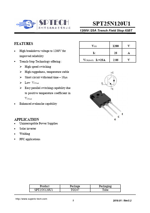
1200V /25A Trench Field Stop IGBTSPT 25N120U1FEATURES∙High breakdown voltage to 1200V for improved reliability∙Trench-Stop Technology offering : High speed switchingHigh ruggedness, temperature stable Short circuit withstand time – 10μs Low V CEsatEasy parallel switching capability dueto positive temperature coefficient in V CEsat∙Enhanced avalanche capabilityAPPLICATION∙Uninterruptible Power Supplies ∙Solar inverter ∙Welding ∙PFC applicationsProductPackage Packaging SPT 25N120U1TO247TubeV CE 1200 V I C25 A V CE(SAT) I C =25A2.05VMaximum RatingsParameter Symbol Value Unit Collector-Emitter Breakdown Voltage V CE1200 V DC collector current, limited by T jmaxT C = 25°C T C = 100°C I C5025ADiode Forward current, limited by T jmaxT C = 25°C T C = 100°C I F5025AContinuous Gate-emitter voltage V GE±20 V Transient Gate-emitter voltage V GE±30 V Turn off safe operating area V CE ≤1200V,T j ≤ 150°C- 75 APulsed collector current, V GE= 15V ,t p limited by T jmaxI CM75 AShort Circuit Withstand Time, V GE= 15V,VCE≤ 600VTsc 10 μs Power dissipation , Tj=25℃Ptot 210 W Operating junction temperature T j-40...+150°C Storage temperature T s -55...+150°CSoldering temperature, wave soldering 1.6mm(0.063in.) from case for 10s- 260 °CThermal ResistanceParameter Symbol Max. Value Unit IGBT thermal resistance,junction - caseRθ(j-c) 0.61 K/WDiode thermal resistance,junction - caseRθ(j-c) 1.2 K/WThermal resistance,junction - ambientRθ(j-a) 40 K/W Electrical Characteristics of the IGBT(T j= 25℃ unless otherwise specified):Parameter Symbol Conditions Min Typ Max Unit StaticCollector-Emitterbreakdown voltageBV CES V GE=0V , I C=250μA 1200 - - V Gate threshold voltage V GE(th)V GE=V CE, I C=250μA 5.4 6.0 6.6 VCollector-Emitter Saturation voltage V CE(sat)V GE=15V, I C=25AT j = 25°CT j = 150°C--2.052.652.45-VZero gate voltage collector current I CESV CE = 1200V, V GE = 0VT j = 25°CT j = 150°C----1001000μAGate-emitter leakage current I GES V CE = 0V, V GE = ±20V - - 100nA Transconductance g fs V CE=20V, I C=25A - 13 - SParameter Symbol Conditions Min Typ Max Unit DynamicInput capacitance C iesV CE = 25V, V GE = 0V,f = 1MHz - 1865 -pFOutput capacitance C oes- 70 - Reverse transfercapacitanceC res- 45 -Gate charge Q G V CC = 960V, I C = 25A,V GE = 15V- 137 - nCShort circuit collector current I C(SC)V GE=15V,t SC≤10usV CC=600V,T j,start=25°C- 140 - ASwitching Characteristic, Inductive LoadParameter Symbol Conditions Min Typ Max Unit Dynamic , at T j = 25°CTurn-on delay time td(on)V CC = 600V, I C = 25A,V GE = 0/15V,R g=42Ω- 62 - nsRise time t r -22-nsTurn-on energy E on -3.3-mJTurn-off delay time td(off)-297-nsFall time t f -94 -nsTurn-off energy E off- 0.65 -mJElectrical Characteristics of the DIODEParameter Symbol Conditions Min. Typ. Max. Unit Dynamic , at T j = 25°CDiode Forward Voltage V FM I F = 25A- 3.1 - VReverse Recovery Time T rrI F= 25A,di/dt= 600A/μs - 420 - nSReverse Recovery Current I rr- 17 - A Reverse Recovery Charge Q rr- 2570 - nCFig. 1 FBSOA characteristicsFig. 2 Load Current vs. FrequencyFig. 3 Output characteristicsFig. 4 Saturation voltage characteristics0.11101001101001000I C (A )VCE(V)01020304050600.1110100I C (A )f (KHz)010203040506012345I C (A )V CE (V)1020304050600123456I C (A )V CE (V )25℃150℃V GE = 20V17V15V 13V11V9VV GE = 15Vt P = 10μs50μs 100μs500μs1msDCT a =25°C, T j ≤150C , V GE =15VD=0.5, V CE =600V,V GE =0/15V, R g =42Ω,T j ≤150C110℃80℃Fig. 5 Switching times vs. gate resistorFig. 6 Switching times vs. collector currentFig. 7 Switching loss vs. gate resistorFig. 8 Switching loss vs. collector current101001000510152025303540455055t , S W I T C H I N G T I M E S[n s ]R g (Ω)td(off)tf td(on)tr101001000102030405060t , S W I T C H I N G T I M E S [n s ]I C (A)td(off)tf td(on)tr00.511.522.533.540510152025303540455055S w i t c h i n g l o s s (m J )R g (Ω)Eoff Eon024681012102030405060S w i t c h i n g l o s s (m J )I c (A)Eoff EonCommon EmitterV CC =600V, V GE = 15V, I C =25A Ta=25℃ Common EmitterV CC = 600V, V GE = 15V, R G =42Ω Ta=25℃Common EmitterV CC =600V, V GE = 15V, I C =25A Ta=25℃Common EmitterV CC = 600V, V GE = 15V, R G =42Ω Ta=25℃Fig. 9 Gate charge characteristicsFig. 10 Capacitance characteristics0369121550100150V G E (V )Qg (nC)240V640V 960V101001000100001112131C a p a c i t a n c eV CE (V)Ciss(pF)Coss(pF)Crss(pF)Common Emitter I C = 25A ,Ta=25℃Common Emitter VGE = 0V, f = 1MHz Ta=25℃。

CLEANING PACKAGES PackagesSYS-050-50000000 (Utility)SYS-050-5001000 (Anti-static)Shop Cleaning PackageSYS-050-52000000 (Utility)SYS-050-5201000 (Anti-static)Vehicle Cleaning PackageSYS-050-53000000(Utility) SYS-050-5301000(Anti-static)Office Cleaning Package AccessoriesSYS-050-50100000(Plastic) SYS-050-50110000(Metal Tools)Shop Cleaning Accessories (no hose)SYS-050-52100000(Plastic) SYS-050-52110000(Metal Tools)Vehicle Cleaning Accessories (no hose)SYS-050-53100000(Plastic) SYS-050-53110000(Metal Tools)Office Cleaning Accessories (no hose)VAC HOLSTERSHolstersSYS-030-52201005Aluminum Vac Holster 1 1/2" & 2" ClawSYS-030-52201000Aluminum Vac Holster For 1 1/2" DetailerSYS-030-522CREVI PVC Crevice Tool HolsterEurovac Cleaning ToolsHolster, Hose & ClawSYS-050-52200000Vac Holster w/15' Hose & ClawSYS-050-52300000Vac Holster w/25' Hose & ClawWET SEPARATORSSYS-050-54500000Mobile Wet Pick-up w/1 1/2" HoseSYS-050-54800000In-Line Wet SeparatorSYS-050-54800100Mobile Wet Separtor 18" SSCLEANING WANDS1 1/2" WandsCLE-UNE-20A13800 1 1/2" x 54" Alum. Wand - Type 9CLE-UNE-20A50000 1 1/2" x 54" 1 Piece Straight Wand (Metal Cpg)CLE-UNE-21A500001-1/2" x 54" 1 Piece Two Curve Wand (Metal Cpg)CLE-UNE-21AP5660 1 1/2" x 56" Alum Wand w/ABS CplgCLE-UNE-22A50000 ** 1 1/2" x 54" 2 pc. Aluminum Wand Metal CplgCLE-UNE-25AHIUP51-1/2" x 60" One Curve Extension WandCLE-UNE-250000001-1/2" x 60" Straight Extension WandCLE-UNE-25HIUPAW1-1/2" x 60" Straight Alum Ext. Wand Alum CplgCLE-UNE-36AP5000 1 1/2" x 36" Aluminum Extension w/ABS CplgCLE-UNE-36P5000 1 1/2" x 36" Plastic Straight Wand2" WandsCLE-UNE-300000002" x 45" One Curve WandCLE-UNE-31AB00002" x 56" Two Curve WandCLE-UNE-32CWC1502" X 54" 2 Piece Two Curve Wand (Fits 1-1/2" Tools)2-1/2" WandsCLE-EUR-0A25C4202-1/2" x 42" 1 Bend Aluminum Nozzle3" WandsCLE-EUR-0A30C4203" x 42" 1 Bend Aluminum WandCLE-EUR-0A30C6003" x 60" 1 Bend Alum Wand3 1/2" WandsCLE-EUR-0A35C420 3 1/2" x 42" 1 Bend Aluminum WandMisc Wand PartsCLE-UNE-200CM8A52" x 8" Steel Adaptor (Fits 1-1/2" Tools)CLE-UNE-21NA5000 1 1/2" Wand Metal Coupling NutSame as picture above CLE-UNE-21NP5000 1 1/2" Wand Plastic Coupling NutCLE-UNE-21R50000 1 1/2" Wand Metal Coupling Ring FLOOR TOOLS1 1/2" Floor ToolsCLE-UNE-313500001-1/2" x 9" Aluminum Wall & Stair BrushCLE-UNE-5355H0011-1/2" x 14" Floor Tool w/ horsehair bristlesCLE-UNE-545500001-1/2" x 14" Floor Tool w/ squeegeeCLE-UNE-598500001-1/2" X 11" Rug & Floor ToolCLE-UNE-63550000 **1-1/2" x 14" Aluminum Floor Tool w/ nylon bristlesCLE-UNE-646500001-1/2" x 14" Aluminum Carpet ToolCLE-UNE-650500001-1/2" x 18" Metal Floor Tool w/ wheelsCLE-UNE-9135000011" Black Air Turbine on wheels - Type 92" Floor ToolsCLE-UNE-314000002" x 13" Aluminum Gulper ToolCLE-UNE-700000002" x 20" Metal Floor Tool w/ wheels2-1/2" Floor ToolsCLE-EUR-0A25C42B Duck Bill Brush Attachment for 2-1/2" Alum Nozzle3" Floor ToolsNo Picture Available CLE-EUR-FT30X1903" x 19" Alum Floor Tool3 1/2" Floor ToolsNo Picture Available CLE-EUR-FT35X190 3 1/2" x 19" Alum Floor ToolCLE-EUR-0A35C42B Duck Bill Brush Attachment fo 3-1/2" Alum NozzleMisc Floor Tool PartsCLE-UNE-635B00006355 Replacement Nylon Brush FLOOR SWEEPSYS-030-501000002" Floor Sweep w/manual slidegate - no tube, bends inc. GULPER/UTILITY TOOLCLE-UNE-2355BK00 1 1/2" x 5" Black Gulper/Utility ToolCLE-UNE-31900000 1 1/2" Orange Claw ToolCLE-UNE-30900000 1 1/2" x 6" Alum Utility NozzleCLE-UNE-321000002" x 4 1/2" Yellow ClawDISPENSING TOOLCLE-JBD-0U156A0O 3 1/2"W STD Car Detailer 400psi Alum ValveCLE-JBD-0U156CA0 3 1/2"W STD Car Detailer 400psi Alum Valve Closed Spray CREVICE TOOLSCLE-UNE-208000002" x 15" Aluminum Crevice ToolCLE-UNE-209ST0002" x 24" Steel Crevice Tool1 1/2" Crevice ToolsCLE-UNE-611A1000 **1-1/2" x 11" Metal Crevice ToolCLE-UNE-611F0000 ** 1 1/2" x 11" Plastic Crevice ToolCLE-UNE-617FBK001-1/2" x 17" Plastice Crevice ToolCLE-UNE-624A10001-1/2" x 24" Aluminum Crevice Tool2" Crevice ToolsCLE-UNE-202000002" x 18" Straight Alum. Pick Up NozzleCLE-UNE-208000002" x 15" Aluminum Crevice ToolCLE-UNE-209ST0002" x 24" Steel Crevice ToolCLE-EUR-200X2502" x 39" Crevice Nozzle2 1/2" Crevice ToolsCLE-EUR-250X250 2 1/2" x 39"L Alum. Crevice Nozzle BRUSH TOOLSCLE-UNE-312000001-1/2" X 5" Aluminum Dust BrushCLE-UNE-313500001-1/2" x 9" Aluminum Wall & Stair BrushCLE-UNE-907G00001-1/2" x 3" Dust Brush - No ReducerCLE-UNE-907GMR00 **1-1/2" x 3" Dust Brush - w/ ReducerUPHOLSTERY TOOLS1 1/2" Upholstery ToolsCLE-UNE-307000001-1/2" x 5" Aluminum Upholstery ToolCLE-UNE-909MR000 **1-1/2" x 5" Upholstery Tool w/ ReducerAdaptors for Brush & Upholstery ToolsCLE-UNE-502000001-1/2" x 1-1/4" Grey Plastic ReducerCLE-UNE-609BK000 1 1/4" Black Adaptor PlasticCLE-UNE-703000001-1/2" X 1-1/4" Aluminum Reducer Misc Upholstery PartsCLE-UNE-307B0000307 Series Replacement BrushCLE-UNE-909B0000909 Series Replacement Brush See above picture CLE-UNE-703000001-1/2" X 1-1/4" Aluminum ReducerTOOL ADAPTORSSee above picture CLE-UNE-703000001-1/2" X 1-1/4" Aluminum ReducerCLE-UNE-200CM8A5 **2" x 8" Steel Adaptor w/ 1-1/2" Tool CplgCLE-UNE-16C000001-1/2" Tool to 2" Hose Extension/Adaptor OVERHEAD TOOLSCLE-UNE-401UE3B04" to 8" Overhead ToolCLE-UNE-403UE3B01" x 4" Pipe Cleaning AttachmentHOSE & TOOL RACKCLE-JBD-IT20B000Hose & Tool Rack - White (Accessories not included)CLE-JBD-IT200000Hose & Tool Rack - Chrome (Accessories not included)FREIGHT: F.O.B. EUROVAC PLANT - ONTARIO, CANADA。

APT75DQ120BGDatasheet Ultrafast Soft Recovery Rectifier DiodeFinalOctober 20181Revision History (1)1.1Revision E (1)1.2Revision D (1)1.3Revision C (1)1.4Revision B (1)1.5Revision A (1)2Product Overview (2)2.1Features (2)2.2Benefits (2)2.3Applications (2)3Electrical Specifications (3)3.1Absolute Maximum Ratings (3)3.2Electrical Performance (3)3.3Dynamic Characteristics (4)3.4Typical Performance Curves (5)3.5Reverse Recovery Overview (8)4Package Specification (9)4.1Package Outline Drawing (9)1Revision HistoryThe revision history describes the changes that were implemented in the document. The changes arelisted by revision, starting with the most current publication.1.1Revision ERevision E was published in October 2018. In this revision, the new template and format was applied.The following is a summary of changes in the revision E of this document.Product image was updated.Product features were updated. For more information, see .Product Overview (see page 2) The lead thickness in the package outline drawing was updated. For more information, see Package.Outline Drawing (see page 9)1.2Revision DRevision D was published in June 2011. In this revision, forward voltage maximum was changed from 3.1V to 3.3 V.1.3Revision CRevision C was published in May 2011. The following is a summary of the changes in revision C of thisdocument.Removed patent information.Changed maximum lead thickness from 0.79 mm (0.031 in.) to 1.016 mm (0.040 in.).1.4Revision BRevision B was published in August 2005. In this revision, the I was changed to 100 μA.RM1.5Revision ARevision A was published in June 2005. It is the first publication of this document.This section outlines the product overview for the APT75DQ120BG device.2.1FeaturesThe following are key features of the APT75DQ120BG device:Ultrafast recovery timesSoft recovery characteristicsLow forward voltageLow leakage currentAvalanche energy ratedRoHS compliantAEC-Q101 qualified2.2BenefitsThe following are benefits of the APT75DQ120BG device:High switching frequencyLow switching lossesLow noise (EMI) switchingHigher reliability systemsIncreased system power density2.3ApplicationsThe APT75DQ120BG device is designed for the following applications:Power factor correction (PFC)Anti-parallel diodeSwitch-mode power supplyInverters/convertersMotor controllersFreewheeling diodeSwitch-mode power supplyInverters/convertersSnubber/clamp diodeSnubber/clamp diode3Electrical SpecificationsThis section shows the electrical specifications for the APT75DQ120BG device.3.1Absolute Maximum RatingsThe following table shows the absolute maximum ratings for the APT75DQ120BG device.All ratings: T = 25 °C unless otherwise specified.CTable 1 • Absolute Maximum RatingsSymbol Parameter Ratings UnitV R Maximum DC reverse voltage1200VV RRM Maximum peak repetitive reverse voltage1200V RWM Maximum working peak reverse voltage1200I F(AV)Maximum average forward current (T = 112 °C, duty cycle = 0.5)C75AI F(RMS)RMS forward current121I FSM Non-repetitive forward surge current (T = 45 °C, 8.3 ms)J540E AVL Avalanche energy (1 A, 40 mH)20mJT , TJ STG Operating and storage temperature range–55 to 175°CT L Lead temperature for 10 seconds300The following table shows the thermal and mechanical characteristics of the APT75DQ120BG device.Table 2 • Thermal and Mechanical CharacteristicsSymbol Characteristic Min Typ Max UnitRθJC Junction-to-case thermal resistance0.31°C/WWt Package weight0.22oz6.2gMaximum mounting torque10lbf-in1.1N-m3.2Electrical PerformanceThe following table shows the static characteristics of the APT75DQ120BG device.Table 3 • Static CharacteristicsSymbol Characteristic Test Conditions Min Typ Max UnitV F Forward voltage I = 75 AF 2.8 3.3VI = 150 AF 3.5I = 75 A, T = 125 °CF J 2.2I RM Maximum reverse leakagecurrent V = 1200 VR100μAV = 1200 V, T = 125 °CR J500C J Junction capacitance V = 200 VR50pF3.3Dynamic CharacteristicsThe following table shows the dynamic characteristics of the APT75DQ120BG device.Table 4 • Dynamic CharacteristicsSymbol Characteristic Test Conditions Min Typ Max Unitt rr Reverse recovery time I = 1 AFdi/dt = –100 A/µsFV = 30 VRT = 25 °CJ32nst rr Reverse recovery time I = 75 AFdi/dt = –200 A/µsFV = 800 VRT = 25 °CC 325Q rr Reverse recovery change715nC I RRM Maximum reverse recovery current5At rr Reverse recovery time I = 75 AFdi/dt = –200 A/µsFV = 800 VRT = 125 °CC 420nsQ rr Reverse recovery charge3340nC I RRM Maximum reverse recovery current13At rr Reverse recovery time I = 75 AFdi/dt = –1000 A/µsFV = 800 VRT = 125 °CC 195nsQ rr Reverse recovery change5810nC I RRM Maximum reverse recovery current42A3.4Typical Performance CurvesThis section shows the typical performance curves for the APT75DQ120BG device.Figure 1 • Maximum Transient Thermal ImpedanceFigure 2 • Forward Current vs. Forward Voltage Figure 3 • RRT vs. Current Rate of ChangeFigure 4 • Reverse Recovery Charge vs. Current Rate of Figure 5 • Reverse Recovery Current vs. Current RateFigure 4 • Reverse Recovery Charge vs. Current Rate of ChangeFigure 5 • Reverse Recovery Current vs. Current Rate of ChangeFigure 6 • Dynamic Parameters vs. Junction TemperatureFigure 7 • Maximum Average Forward Current vs. Case TemperatureFigure 8 • Junction Capacitance vs. Reverse VoltageFigure 8 • Junction Capacitance vs. Reverse Voltage1. 2. 3. 4. 5. 3.5Reverse Recovery OverviewThe following illustration shows the diode test circuit for the APT75DQ120BG device.Figure 9 • Diode Test CircuitThe following illustration shows the diode reverse recovery waveform and definitions for the APT75DQ120BG device.Figure 10 • Diode Reverse Recovery Waveform and DefinitionsI —Forward conduction current.F di /dt—Rate of diode current change through zero crossing.F I —Maximum reverse recovery current.RRM t —Reverse recovery time, measured from zero crossing where diode current goes from positive to rr negative, to the point at which the straight line through I and 0.25 I passes through zero.RRM • RRM Q —Area under the curve defined by I and t .rr RRM rr4Package SpecificationThis section shows the package specification for the APT75DQ120BG device.4.1Package Outline DrawingThis section shows the TO-247 package drawing of the APT75DQ120BG device. Dimensions are inmillimeters and (inches).Figure 11 • Package Outline DrawingMicrosemi HeadquartersOne Enterprise, Aliso Viejo,CA 92656 USAWithin the USA: +1 (800) 713-4113Outside the USA: +1 (949) 380-6100Sales: +1 (949) 380-6136Fax: +1 (949) 215-4996Email:***************************© 2018 Microsemi. All rights reserved. Microsemi and the Microsemi logo are trademarks of Microsemi Corporation. All other trademarks and service marks are the property of their respective owners.Microsemi makes no warranty, representation, or guarantee regarding the information contained herein or the suitability of its products and services for any particular purpose, nor does Microsemi assume any liability whatsoever arising out of the application or use of any product or circuit. The products sold hereunder and any other products sold by Microsemi have been subject to limited testing and should not be used in conjunction with mission-critical equipment or applications. Any performance specifications are believed to be reliable but are not verified, and Buyer must conduct and complete all performance and other testing of the products, alone and together with, or installed in, any end-products. Buyer shall not rely on any data and performance specifications or parameters provided by Microsemi. It is the Buyer's responsibility to independently determine suitability of any products and to test and verify the same. The information provided by Microsemi hereunder is provided "as is, where is" and with all faults, and the entire risk associated with such information is entirely with the Buyer. Microsemi does not grant, explicitly or implicitly, to any party any patent rights, licenses, or any other IP rights, whether with regard to such information itself or anything described by such information. Information provided in this document is proprietary to Microsemi, and Microsemi reserves the right to make any changes to the information in this document or to any products and services at any time without notice.Microsemi, a wholly owned subsidiary of Microchip Technology Inc. (Nasdaq: MCHP), offers a comprehensive portfolio of semiconductor and system solutions for aerospace & defense, communications, data center and industrial markets. Products include high-performance and radiation-hardened analog mixed-signal integrated circuits, FPGAs, SoCs and ASICs; power management products; timing and synchronization devices and precise time solutions, setting the world's standard for time; voice processing devices; RF solutions; discrete components; enterprise storage and communication solutions; security technologies and scalable anti-tamper products; Ethernet solutions; Power-over-Ethernet ICs and midspans; as well as custom design capabilities and services. Microsemi is headquartered in Aliso Viejo, California, and has approximately 4,800 employees globally. Learn more at www. .053-4229。

Meggitt SA, Route de Moncor 4, Case postale, 1701 Fribourg, SwitzerlandTel: +41 26 407 11 11Fax: +41 26 407 13 01*****************.com/energyInformation contained in this document may be subject to export control regulations of the European Union, USA or other countries. Each recipient of this document is responsible for ensuring that transfer or use of any information contained in this documentcomplies with all relevant export control regulations. ECN N/A.DATA SHEETKEY FEATURES AND BENEFITS•From the vibro -meter ® product line •Voltage output signal: 100 or 500 mV/ g •Frequency response: 0.5 to 14 000 Hz (100 mV/ g versions) 0.2 to 3 700 Hz (500 mV/ g versions)•Temperature range:−55 to 120 °C (100 mV/ g versions) −55 to 90 °C (500 mV/ g versions)•Isolated electronics with internal shield for reduced noise and improved bias-voltage stability•Ground isolated from case•Available as a sensor only or with an integral cable•Available in standard versions andEx versions certified for use in hazardous areasAPPLICATIONS•General-purpose vibration monitoring in harsh industrial environments and /or hazardous areasDESCRIPTIONThe CE620 piezoelectric accelerometer with integrated electronics from Meggitt’svibro -meter ® product line is a general-purpose vibration sensor designed for the monitoring and protection of machinery in harsh industrial environments.The CE620 is an industry standard IEPE (integrated electronics piezo electric) vibration sensor that requires a constant current power supply and provides a dynamic vibration output signal (AC voltage) on a bias level (DC voltage). It is available with a sensitivity of either 100 or 500 mV/ g .The CE620 is available as a sensor only or fitted with an integral cable that is protected by astainless-steel overbraid. Sensor only versions allow one of a range of different cable assemblies to be used to connect the sensor to the monitoring system, depending on the application and environment.The CE620 is available in standard versions for use in standard (non-hazardous) areas andEx versions for installation in hazardous areas (potentially explosive atmospheres).For specific applications, contact your local Meggitt representative.(sensor only version)DATA SHEETCE620 piezoelectric accelerometer with integrated electronics 2 / 9Document reference DS 262-214Version 9 – 02.12.2022SPECIFICATIONSNote: Unless otherwise stated, all values listed are typical values, referenced at 24°C (75°F). OperatingSensitivity•100 mV/g versions(ordering option code B100):100 mV/g ±5%•500 mV/g versions(ordering option code B500):500 mV/g ±5%Dynamic range•100 mV/g versions:±80g peak•500 mV/g versions:±16g peakTransverse sensitivity:<5%Linearity:±1% maximumFrequency response•100 mV/g versions:1 to 9000Hz (±10%).0.5 to 14000Hz (±3dB).•500 mV/g versions:0.4 to 1600Hz (±10%).0.2 to 3700Hz (±3dB).Resonant frequency•100 mV/g versions:25kHz nominal•500 mV/g versions:16kHz nominalTemperature response (sensitivity deviation)•−55°C (−67°F):−10% typical•120°C (−248°F):+5% typicalNote: Reference at 20°C (68°F).ElectricalPower supply voltage(for current source):22 to 28V DCPower supply current:2 to 10mABias voltage (4mA supply)•100 mV/g versions(ordering option code B100):12V DC nominal•500 mV/g versions(ordering option code B500):10V DC nominalOutput impedance:50Ω nominalResidual electrical noise•100 mV/g versions:30μg/√H z at 1Hz, 6μg/√H z at 10Hz,5μg/√H z at 100Hz, 5μg/√H z at 1000Hz•500 mV/g versions:20μg/√H z at 0.1Hz, 6μg/√H z at 1Hz, 2μg/√H z at 10Hz,2μg/√H z at 100Hz, 2μg/√H z at 1000HzGrounding:Isolated from case (machine ground), internally shielded Internal isolation(case to shield):100MΩ minimumReverse polarity:ProtectedOvervoltage:ProtectedDocument reference DS 262-214Version 9 – 02.12.2022DATA SHEETCE620 piezoelectric accelerometer with integrated electronics3 / 9EnvironmentalTemperature range •100 mV/ g versions(ordering option code B100):−55 to 120 °C (−67 to 248 °F)•500 mV/ g versions(ordering option code B500):−55 to 90 °C (−67 to 194 °F)Humidity:IP68 (according to IEC 60529)Shock vibration limit:5 000 g peak Continuous vibration limit :500 g peak Base strain sensitivity:0.000 2 g peak / μεElectromagnetic sensitivity (50 Hz, 0.03 T):0.2 gPotentially explosive atmospheresAvailable in Ex approved versions for use in hazardous areasType of protection Ex ia: intrinsic safety (ordering option code A2)EuropeEC type examination certificateI M1Ex ia I MaII 1 GD (Zones 0, 1, 2, 20, 21, 22)Ex ia IIC T4 GaEx ia IIIC T135°C Da LCIE 20 ATEX 3039 XInternationalIECEx certificate of conformityEx ia I MaEx ia IIC T4 GaEx ia IIIC T135°C Da IECEx LCIE 20.0026XRussian FederationEA ЭC RU certificate of conformity *PO Ex ia I Ma X 0Ex ia IIC T4 Ga X Ex ia IIIC T135°C Da XEA ЭC RU C-CH.A Д07.B.03042/21* N ot engraved/marked on the products.For specific parameters of the mode of protection concerned and special conditions for safe use, refer to the Ex certificates that are available from Meggitt SA.For the most recent information on the Ex certifications that are applicable to this product, refer to the Ex product register (PL-1511) document that is available from Meggitt SA.Approvals Conformity:European Union (EU) declaration of conformity (CE marking)Electromagnetic compatibility (EMC):EMC compliant (2014/30/EU).EN 61326-1.Environmental management :RoHS compliant (2011/65/EU)Hazardous areas:Ex approved versions(see Potentially explosive atmospheres on page 3)DATA SHEETCE620 piezoelectric accelerometer with integrated electronics 4 / 9Document reference DS 262-214Version 9 – 02.12.2022PhysicalCase material:Stainless steel (AISI316L, DIN1.4404)Dimensions:See Mechanical drawings starting on page5Weight•Sensor only versions:85 g (0.19 lb) approx.•Integral cable versions:60 g/m (0.04 lb/ft) approx.ConnectorSensor version:Sensor only versions (PNR 444-620-000-111).See Sensor only versions on page5.Connector type:MIL-C-5015-10SL-4P – rugged circular, threaded coupling, 2-pinconnector with keyway.Note: Mates with MIL-C/DTL-5015 type connectors, as used by therecommended cable assemblies.Connector pinouts (pin allocation)•Pin A(+):Power supply and output signal•Pin B(−):CommonRecommended cable assemblies:EC318, EC319, EC622 and EC632 (see Accessories on page7) CableSensor version:Integral cable versions (PNR 444-620-000-211).See Integral cable versions on page6.Cable type:Cable: Teflon® FEP cable, twisted-pair shielded, Ø4.8 ± 0.2mm.Conductors: 2 × 0.5 mm2 twisted cores.Overbraid: Stainless steel (AISI316L).Outer diameter: Ø5.2 ± 0.3mm (0.20″).Maximum temperature: 200°C (392°F).Weight: See Physical on page4.Cable pinouts (flying lead allocation)•Red (+) wire:Power supply and output signal•White(−) wire:CommonMountingStud or adaptor:1/4″-28UNF-2A (see Accessories on page7)Torque:2.4 N•m (1.8 lb-ft).Refer also to the CExxx and PVxxx vibration sensors(piezoelectric accelerometers and piezoelectric velocity sensors)installation manual.CalibrationDynamic calibration at factory. No subsequent calibration necessary.Document reference DS 262-214Version 9 – 02.12.2022DATA SHEETCE620 piezoelectric accelerometer with integrated electronics5 / 9MECHANICAL DRAWINGSSensor only versionsCE620 accelerometerSensitivity (B)100 mV/ g 100500 mV/ g500Ordering number (PNR):444 - 620 - 000 - 111Environment (A)Standard 1Explosive (Ex)2A B CConnector (C)01MIL-C-5015-10SL-4PNotesAll dimensions in mm (in) unless otherwise stated.For the sensor only versions of the CE620, the sensor mates with MIL-C/DTL-5015 type connectors. Not all combinations of sensor ordering option codes (A , B and C ) are available.See also Ordering information on page 7 and the ECxxx cable assemblies in Accessories on page 7.M8 × 1.251/4 ″-28UNF-2A46.5(0.16 ″)(0.26 ″)(0.02 ″)1/4 ″-28UNF 1/4 ″-28UNF-2A46.5(0.16 ″)(0.26 ″)(0.02 ″)Adaptor studsDATA SHEETCE620 piezoelectric accelerometer with integrated electronics 6 / 9Document reference DS 262-214Version 9 – 02.12.2022Integral cable versionsMECHANICAL DRAWINGS(continued)M8 × 1.251/4 ″-28UNF-2A46.5(0.16 ″)(0.26 ″)(0.02 ″)1/4 ″-28UNF 1/4 ″-28UNF-2A46.5(0.16 ″)(0.26 ″)(0.02 ″)Sensitivity (B)100 mV/ g100Ordering number (PNR):444 - 620 - 000 - 211Environment (A)Standard 1Explosive (Ex)2Integral cable length (L)055 m 1010 mA B C LCable (C)72Integral FEP cable with overbraidAll dimensions in mm (in) unless otherwise stated.For the integral cable versions of the CE620, the length of cable is defined at the time of ordering. Not all combinations of sensor ordering option codes (A , B , C and L ) are available. See also Ordering number (PNR) below and the Ordering information on page 7.Adaptor studsCE620 accelerometerDocument reference DS 262-214 Version 9 – 02.12.2022DATA SHEET CE620 piezoelectric accelerometer with integrated electronics7 / 9ORDERING INFORMATIONTo order, please specify the version(s) of the CE620 piezoelectric accelerometer with integrated electronics required…Standard (non-Ex) versions:Type Designation Ordering number (PNR)CE620100mV/g sensor only version444-620-000-111-A1-B100-C01 CE620500mV/g sensor only version444-620-000-111-A1-B500-C01 CE620100mV/g integral cable version – 5m cable length 444-620-000-211-A1-B100-C72-L05 CE620100mV/g integral cable version – 10m cable length 444-620-000-211-A1-B100-C72-L10 Ex versions (for use in hazardous areas):Type Designation Ordering number (PNR)CE620100mV/g sensor only version444-620-000-111-A2-B100-C01 CE620100mV/g integral cable version – 5m cable length 444-620-000-211-A2-B100-C72-L05 CE620100mV/g integral cable version – 10m cable length 444-620-000-211-A2-B100-C72-L10 NotesOnly CE620 sensors with the specific ordering numbers (PNRs) listed above are available to order.That is, not all combinations of sensor ordering option codes (A, B, C and L) are available.For example, Ex versions of the CE620 sensor with a sensitivity of 500mV/g are not available.ACCESSORIESSuppliedItem Type Part number (PNR)•Adaptor studs1/4-28UNF(1/4″-28UNF-2A to 1/4″-28UNF-2A)809-601-000-011M8×1.25(1/4″-28UNF-2A to M8×1.25)809-601-000-021 Note: One of each of these type of adaptor studs is supplied with a CE620, that is, one M8×1.25 and one1/4″-28UNF.OptionalItem Type Part number (PNR)•Adaptor studs M8×1(1/4″-28UNF-2A to M8×1)809-601-000-031DATA SHEETCE620 piezoelectric accelerometer with integrated electronics 8 / 9Document reference DS 262-214Version 9 – 02.12.2022Optional(continued)Item Type Part number (PNR)•Cable assemblies EC318.Standard version with a 2-pin MIL-C/DTL-5015 type connector,2-wire RADOX® cable.922-318-000-002EC318.Standard version with a 2-pin MIL-C/DTL-5015 type connector,2-wire RADOX® cable and cable protection (flexible stainless-steelhose).922-318-000-403EC319.Splashproof version with a 2-pin MIL-C/DTL-5015 type connector,2-wire RADOX® cable.922-319-000-002EC319.Splashproof version with a 2-pin MIL-C/DTL-5015 type connector,2-wire RADOX® cable and cable protection (sealed, flexiblestainless-steel hose).922-319-000-103EC622.Standard version with a 2-pin MIL-C/DTL-5015 type connector,2-wire Polyurethane (PUR) cable, IP67cable boot (overmold).922-622-000-001EC632.Higher-temp. version with a 2-pin MIL-C/DTL-5015 type connector,2-wire Teflon® FEP cable, IP67cable boot (overmold).922-632-000-001EC632.Higher-temp. version with a 2-pin MIL-C/DTL-5015 type connector,2-wire Teflon® FEP cable, IP67cable boot (overmold) and cableprotection (stainless steel (AISI316L) overbraid).922-632-000-101NotesThe cable length must be specified when ordering a cable assembly.When ordering a EC31x cable assembly, the ordering option code -L or -U is used to specify the overall cable length.EC31x cable assemblies can be specified with any cable length.When ordering a EC6x2 cable assembly, the ordering option code -L is used to specify the overall cable length.EC6x2 cable assembles must be specified with a standard length of 2, 5, 10, 15, 20 or 30m (corresponding to ordering option codes of L2000, L5000, L10000, L15000, L20000 or L30000, respectively).Refer to the cable assembly product drawings for further information.Item Type Part number (PNR)•Mounting adaptor MA122_012(1/4″-28UNF-2A to M6, with a conic base)809-122-000-012•Insulating stud MA122_021(1/4″-28UNF-2A to M6, with a conic base)809-122-000-021ACCESSORIES(continued)Meggitt (Meggitt PLC) is a leading international engineering company, headquartered in England, that designs and delivers high-performance components and subsystems for aerospace, defence and selected energy markets. Meggitt comprises four customer-aligned divisions:Airframe Systems, Engine Systems, Energy&Equipment and Services&Support.The Energy&Equipment division includes the Energy Sensing and Controls product group that specialises in sensing and monitoring solutions for a broad range of energy infrastructure, and control valves for industrial gas turbines, primarily for the Power Generation, Oil & Gas and Services markets. Energy & Equipment is headquartered in Switzerland (Meggitt SA) and incorporates the vibro-meter® product line, which has over 65 years of sensor and systems expertise and is trusted by original equipment manufacturers (OEMs) globally.All information in this document, such as descriptions, specifications, drawings, recommendations and other statements, is believed to be reliable and is stated in good faith as being approximately correct, but is not binding on Meggitt (Meggitt SA) unless expressly agreed in writing. Before acquiring and/or using this product, you must evaluate it and determine if it is suitable for your intended application. You should also check our website at /energy for any updates to data sheets, certificates, product drawings, user manuals, service bulletins and/or other instructions affecting the product.Unless otherwise expressly agreed in writing with Meggitt SA, you assume all risks and liability associated with use of the product. Anyrecommendations and advice given without charge, whilst given in good faith, are not binding on Meggitt SA. Meggitt (Meggitt SA) takes no responsibility for any statements related to the product which are not contained in a current Meggitt SA publication, nor for anystatements contained in extracts, summaries, translations or any other documents not authored and produced by Meggitt SA.The certifications and warranties applicable to the products supplied by Meggitt SA are valid only for new products purchased directly from Meggitt SA or from an authorised distributor of Meggitt SA.In this publication, a dot (.) is used as the decimal separator and thousands are separated by thin spaces. Example: 12345.67890.Copyright© 2022 Meggitt SA. All rights reserved. The information contained in this document is subject to change without prior notice. Sales offices Local representative Head officeMeggitt has offices in more than 30countries. For a complete list, please visit our website.Meggitt SARoute de Moncor 4Case postale1701 FribourgSwitzerlandTel: +41 26 407 11 11Fax: +41 26 407 13 01*****************.com /energy Document reference DS 262-214Version 9 – 02.12.2022DATA SHEETCE620 piezoelectric accelerometer with integrated electronics9 / 9 RELATED PRODUCTSCE630Piezoelectric accelerometer(100 or 500 mV/g output, side connector):Refer to corresponding data sheetCE687Piezoelectric accelerometer(4 to 20 mA output proportional to g):Refer to corresponding data sheetPV660Piezoelectric velocity sensor(4 mV/m m/s output):Refer to corresponding data sheetPV685Piezoelectric velocity sensor(4 to 20 mA output proportional to mm/s):Refer to corresponding data sheet。
Programmable AttenuatorRCDAT-4000-120Product OverviewMini-Circuits’ RCDAT-4000-120 is a general purpose, single channel programmable attenuator suitable for a wide range of signal level control applications from 1 MHz to 4 GHz. The Attenuator provides 0 to 120 dB attenuation in 0.25 dB steps. Its unique design maintains linear attenuation change per dB, even at the highest attenuation settings.The attenuator is housed in a compact and rugged package with SMA female connectors on the bi-directional input and output RF ports, a standard Ethernet port (RJ45) and a USB type Mini-B power and control port.The attenuator can be controlled via USB or Ethernet (supporting both HTTP and Telnet network protocols). Full software support is provided and can be downloaded from our website any time at /softwaredownload/patt.html. The package includes our user-friendly GUI application for Windows ® and a full API with programming instructions for Windows ® and Linux ® environments (both 32-bit and 64-bit systems).USB / Ethernet50Ω 0 – 120 dB, 0.25 dB step 1 to 4000 MHzTrademarks: Windows is a registered trademark of Microsoft Corporation in the United States and other countries. Linux is a registered trademark of Linus Tor-valds. Mac is a registered trademark of Apple Corporation. Pentium is a registered trademark of Intel Corporation. Neither Mini-Circuits nor the Mini-Circuits RCDAT-series attenuators are affiliated with or endorsed by the owners of the above referenced trademarks.Mini-Circuits and the Mini-Circuits logo are registered trademarks of Scientific Components Corporation.Rev. JECO-012291EDR-11169Case Style: MS1897Software PackageThe Big Deal• Wide attenuation range, 120 dB • Fine attenuation resolution, 0.25 dB• Short attenuation transition time (650 ns)• Compact size, 2.5 x 3.0 x 0.85”• USB and Ethernet controlIncluded AccessoriesModel No.DescriptionQty.MUSB-CBL-3+3.3 ft. USB cable1Applications• Automated Test Equipment (ATE)• WiMAX, 3G, 4G, LTE, DVB Fading Simulators • Laboratory Instrumentation • Handover system Evaluation • Power level cycling1 Attenuator RF ports are interchangeable, and support simultaneous, bidirectional signal transmission, however the specifications are guaranteed for the RF in and RF out as noted on the label. There may be minor changes in performance when injecting signals to the RF Out port.2 Max accuracy defined as ±[absolute error+% of attenuation setting] for example when setting the attenuator to 110 dB attenuation the maximum error at 3500 MHz will be: ±(-7.0+0.1x110)= ±(-7.0+11)= ± 4.0 dB3 Isolation is defined as max attenuation plus insertion loss; this is the path loss through the attenuator when initially powered up. After a brief delay (~0.5 sec typically) the attenuator will revert to a user defined “power-up” state (either max attenuation or a pre-set value).4 Total operating input power from both RF In and RF Out out ports. Compression level not noted as it exceeds max safe operating power level.5 Tested with 1 MHz span between signals.6 Minimum Dwell Time is the time the RCDAT will take to respond to a command to change attenuation states without communication delays. In PC control add communication delays (on the order of msec for USB) to get actual response time.7Attenuation Transition Time is specified as the time between starting to change the attenuation state and settling on the requested attenuation state. Electrical Specifications 1 at 0°C to 50°CAbsolute Maximum RatingsOperating Temperature0°C to 50°CStorage Temperature-20°C to 85°CV USB Max.6VDC voltage at RF port16VTotal RF power for RF In & RF Out @ 1 to 10 MHz+13 dBm @ 10 to 6000 MHz+23 dBmPermanent damage may occur if any of these limits are exceeded. Operating in the range between operating power limits and absolute maximum ratings for extended periods of time may result in reduced life and reliability.Block DiagramConnectionsRF In (SMA female)RF Out (SMA female)USB(USB type Mini-B female)Network (Ethernet/LAN)(RJ45 socket)RCDAT response to communication interruptUSBSimultaneous, bidirectional RF signal transmission with symmetrical performanceRJ45(Ethernet)inchConnectionsRF IN (SMA female)RF OUT (SMA female)USB(USB type Mini-B female)Network (Ethernet/LAN)(RJ45 socket)4X #2-56 UNCQBracket OptionTop ViewBottom View2X SMA FEMALEInstruction for mounting bracket:1. Tool required: Phillips head screwdriver2. Mount the bracket over threaded holes on the bottom side with the fasteners provided with the bracket.Outline Drawing (MS1897)Typical Performance Curves-3.0-2.0-1.00.01.02.00100020003000400050006000Frequency (MHz)Attenuation Accuracy @ +25°Cvs. Frequency over Attenuation settingsA c c u r a c y (dB )-3.0-2.0-1.00.01.02.0Frequency (MHz)Attenuation Accuracy @ 0°Cvs. Frequency over Attenuation settingsA c c u r a c y (dB )-3.0-2.0-1.00.01.02.0Frequency (MHz)Attenuation Accuracy @ +50°Cvs. Frequency over Attenuation settingsA c c u r a c y (dB )0.030.060.090.0120.0150.0Frequency (MHz)vs. Frequency over Attenuation settings 0.030.060.090.0120.0150.0Frequency (MHz)vs. Frequency over Attenuation settings A t t e n u a t i o n (d B )0.030.060.090.0120.0150.0Frequency (MHz)vs. Frequency over Attenuation settings A t t e n u a t i o n (d B )A t t e n u a t i o n (dB )11000 2000 3000 4000 5000 60001 1000 2000 3000 4000 5000 60001 1000 2000 3000 4000 5000 60001 1000 2000 3000 4000 5000 60001 1000 2000 3000 4000 5000 60001 1000 2000 3000 4000 5000 6000Attenuation relative to Insertion Loss @ +25°C vs. Frequency over Attenuation settingsAttenuation relative to Insertion Loss @ 0°C vs. Frequency over Attenuation settingsAttenuation relative to Insertion Loss @ +50°Cvs. Frequency over Attenuation settingsFrequency (MHz)Frequency (MHz)Frequency (MHz)Frequency (MHz)Frequency (MHz)Frequency (MHz)Typical Performance Curves (Continued)Frequency (MHz)Attenuation Setting (dB)A t t e n u a t i o n A c c u r a c y (dB )24681012I n s e r t i o n L o s s (d B )Insertion Loss @ Input Power=0dBm Insertion Loss @ Input Power +20 dBmvs. Frequency over TemperaturesI n s e r t i o n L o s s (d B )Insertion Loss @ Input Power=+20dBm Insertion Loss @ Input Power 0dBm vs. Frequency over Temperatures1 1000 2000 3000 40005000 6000Frequency (MHz)Input VSWR @ +25°Cvs. Frequency over Attenuation settings1.01.21.41.61.82.02.22.4I n p u t V S W R (:1)vs. Frequency over Attenuation settings1 1000 2000 3000 4000 5000 6000Frequency (MHz)Output VSWR @ +25°Cvs. Frequency over Attenuation settings1.01.21.41.61.82.02.22.4O u t p u t V S W R (:1)vs. Frequency over Attenuation settings1 1000 2000 3000 4000 5000 6000Frequency (MHz)Input IP3 @ 0dB Attenuation vs. Frequency over TemperaturesI P 3(d B m )IP3@0dB Attenuation Frequency (MHz)Software & Documentation Download:• Mini-Circuits’ full software and support package including user guide, Windows GUI, DLL files, programming manual and examples can be downloaded free of charge from /softwaredownload/patt.html • Please contact ****************************** for supportGraphical User Interface (GUI) for Windows Key Features:• Manual attenuation setting• Sweep and Hop attenuation sequences directed from the PC, or entire sequence loaded into RCDAT.• Attenuator address configuration and Firmware upgrade • Attenuation at power up may be set to selected attenuation level or last attenuation state recorded.• USB, HTTP or Telnet control of RCDAT • Setting Ethernet configurationApplication Programming Interface (API)Programming manual: https:///softwaredownload/Prog_Manual-6-Programmable_Attenuator.pdfWindows Support:• API DLL files exposing the full switch functionality• ActiveX COM DLL file for creation of 32-bit programs • .Net library DLL file for creation of 32 / 64-bit programs• Supported by most common programming environments (refer to application note AN-49-001 for summary of tested environments)Linux Support:• Full attenuator control in a Linux environment is achieved by way of USB interrupt commands.ModelDescriptionRCDAT-4000-120USB/Ethernet Programmable AttenuatorOrdering Information Additional NotesA. Performance and quality attributes and conditions not expressly stated in this specification document are intended to be excluded and do not form a part of this specification document.B. Electrical specifications and performance data contained in this specification document are based on Mini-Circuit’s applicable established test performance criteria and measurement instructions.C. The parts covered by this specification document are subject to Mini-Circuits standard limited warranty and terms and conditions (collectively, “Standard Terms”); Purchasers of this part are entitled to the rights and benefits contained therein. For a full statement of the Standard Terms and the exclusive rights and remedies thereunder, please visit Mini-Circuits’ website at /MCLStore/terms.jspIncluded Accessories Part No.DescriptionMUSB-CBL-3+3.3 ft (1.0 m) USB Cable: USB type A(Male) to USB typeMini-B(Male)Optional AccessoriesDescriptionUSB-AC/DC-5 8,9AC/DC 5V DC Power Adapter with US, EU, IL, UK, AUS, and China power plugsMUSB-CBL-3+ (spare) 3.3 ft (1.0 m) USB Cable: USB type A(Male) to USB type Mini-B(Male)MUSB-CBL-7+ 6.6 ft (2.0 m) USB Cable: USB type A(Male) to USB type Mini-B(Male) CBL-RJ45-MM-5+ 5 ft (1.5 m) Ethernet cable: RJ45(Male) to RJ45(Male) Cat 5E cableBKT-66-02+Bracket Kit8 The USB-AC/DC-5 may be used to provide the 5VDC power input via USB port if operating the RCDAT with Ethernet control. Notrequired if using USB control.9 Power plugs for other countries are also available, Plugs for other countries are also available, if you need a power plug for a country not listed please contact ******************************。
Pirani Standard Gauge PVG-500 PVG-502 Quick Reference Card Pirani Standard GaugePVG-500PVG-502Operating ManualIncl. EC Declaration of Conformitytqna69e1 2 (2012-03)Product IdentificationIn all communications with Agilent, please specify the in-formation on the product nameplate. For convenient refe-rence copy that information into the space provided below.ValidityThis document applies to products with the following partnumbers:W filamentPVG500KF16 (DN 16 ISO-KF, w/o switching functions)PVG500KF16S (DN 16 ISO-KF, with switching functions)PVG500CF16 (DN 16 CF-R, w/o switching functions)PVG500CF16S (DN 16 CF-R, with switching functions)Ni filamentPVG502KF16S (DN 16 ISO-KF, with switching functions)PVG502CF16S (DN 16 CF-R, with switching functions)The part number (PN) can be taken from the product name-plate.We reserve the right to make technical changes without priornotice.All dimensions in mm.Intended UseThe Pirani Standard Gauges PVG-500 and PVG-502 havebeen designed for vacuum measurement of gases in thepressure range of 5×10⁻⁴ … 1000 mbar.They must not be used for measuring flammable or com-bustible gases in mixtures containing oxidants (e.g. atmos-pheric oxygen) within the explosion range.They can be operated in connection with an Agilent controlleror with another controller.SafetySymbols UsedInformation on preventing any kind of physical injury.Personnel QualificationsGeneral Safety Instructions•Adhere to the applicable regulations and take the nec-essary precautions for the process media used.Consider possible reactions between the materials andthe process media.Consider possible reactions (e.g. explosion) of theprocess media due to the heat generated by the product.•Adhere to the applicable regulations and take the neces-sary precautions for all work you are going to do and con-sider the safety instructions in this document.•Before beginning to work, find out whether any vacuumcomponents are contaminated. Adhere to the relevant re-gulations and take the necessary precautions when hand-ling contaminated parts.Communicate the safety instructions to all other users.Liability and WarrantyAgilent assumes no liability and the warranty becomes nulland void if the end-user or third parties•disregard the information in this document•use the product in a non-conforming manner•make any kind of interventions (modifications, alterationsetc.) on the product•use the product with accessories not listed in the productdocumentation.The end-user assumes the responsibility in conjunction withthe process media used.Gauge failures due to contamination or wear and tear, aswell as expendable parts (e.g. filament), are not covered bythe warranty.Technical DataMeasurement principle thermal conductance accordingto PiraniMeasurement range(air, O2, CO, N2)5×10⁻⁴ … 1000 mbarAccuracy (N2)1×10⁻³ … 100 mbar ±15% of reading-4-3VDC 0 … +10.3VDC +1.9 … +10.0logarithmic1.286 V/decadeError signalFilament ruptureVV0 … +0.5+0.1Output impedance Ω2×4.7Switching functions SP1, SP2Threshold value indi-cation and settingone tactile switch at measure-ment value output. Press brieflyfor threshold indication. Keeppressing or press repeatedly forthreshold setting.Setting range 2×10⁻³ … 500 mbarHysteresis 10% above lower thresholdRelay contactclosedopen30 V, 0.5 ADC, floatingat low pressure (LED is lit)at high pressure, error, missingsupply(max. starting current)Power consumption W ≤1Fuse required 1)AT(slow)1Electrical connection FCC 68 / RJ45 applianceconnector, 8-pin, maleSensor cable 8-pin plus shieldingCable length ≤100 m (8×0.14 mm2)Grounding concept → "Power Connection"Vacuum connection tosignal commonconnected via 1 MΩ(voltage difference <15 V)Supply common tosignal commonconducted separately, fordifferential measurementMaterials exposed tovacuumDIN 1.4301, DIN 1.4305,DIN 1.4435, glass, Ni,NiFeFilamentPVG-500PVG-502WNiInternal volume cm3≈1.5Admissible pressure bar(abs.)10, limited to inertgases1)Agilent controllers fulfill these requirements.Admissible temperaturesOperation °C +5 … +60Vacuum connection °C 80Filament °C 110Storage °C –20 … +65Relative humidity % ≤80 at temperatures up to≤+31 °C, decreasing to 50at +40 °CUse indoors only, altitude up to2000 m NNMounting orientation anyDegree of protection IP40Dimensions mmWeightDN 16 ISO-KFDN 16 CF-Rgg80100Measurement Signal vs. Pressurep = 10((U-c)/1.286)⇔U = c + 1.286 × log10 pvalid in the range 5×10⁻⁴ mbar <p< 1000 mbar3.75×10-4 Torr <p< 750 Torr5×10-2 Pa <p< 1×10⁵ PaU p c U p c[V] [mbar] 6.143 [V] [micron] 2.448[V] [µbar] 2.287 [V] [Pa] 3.572[V] [Torr] 6.304 [V] [kPa] 7.429[V] [mTorr] 2.448where p pressureU measurement signalc constant (depending on pressure unit)Gas Type DependencePressure reading (gauge adjusted for air)10101001010101010101001010p (mbar)peff(mbar)Calibration factors for the pressure range below 1 mbarp eff = C × pressure readingGastypeCalibrationfactor CGas type Calibrationfactor CHeNeArKrXe0.81.41.72.43.0H2air, O2, CO, N2CO2water vaporfreon 120.51.00.90.50.7InstallationVacuum ConnectionDANGERDANGER: overpressure in the vacuum system>1 barInjury caused by released parts and harmcaused by escaping process gases can result ifclamps are opened while the vacuum system ispressurized.Do not open any clamps while the vacuum sys-tem is pressurized. Use the type of clamps whichare suited to overpressure.DANGERDANGER: overpressure in the vacuum system>2.5 barKF connections with elastomer seals (e.g.O-rings) cannot withstand such pressures. Pro-cess media can thus leak and possibly damageyour health.Use O-rings provided with an outer centeringring.The gauge may be mounted in any orientation. Tokeep condensates and particles from getting into themeasuring chamber preferably choose a horizontalto upright position and possibly use a seal with acentering ring and filter. If adjustment should bepossible after the gauge has been installed, be sureto install it so that the button can be accessed with apin (→ "Adjusting the Gauge").Remove the protective lid and install the product to the vac-uum system.and filterKeep the protective lid.Original: English tqna69e1 (2012-03)2tqna69e1 3 (1209) PVG50x.omPower ConnectionMake sure the vacuum connection is properly made (→ "Vacuum Connection").If no sensor cable is available, make one according tothe following diagram.Electrical connection Pin 1 Supply Pin 2 Supply common, GND Pin 3 Measurement signal or thresholds SP1/2Pin 4 Gauge identification Pin 5 Signal commonPin 6, 8 Relay SP2, closing contact Pin 7, 8 Relay SP1, closing contact FCC-68connectorConnect the sensor cable to the gauge and the control-ler.OperationWhen the supply voltage is applied, the measurement signal is available between pins 3 and 5 (relationship between measurement signal and pressure → "Technical Data"). Allow a stabilization period of at least 10 minutes. It is advis-able to operate the gauge continuously, irrespective of the pressure.Gas Type DependenceThe measurement value is gas dependent. The pressure reading applies to dry air, O 2, CO and N 2. For other gases, it has to be corrected (→ "Technical Data").If the gauge is operated with an Agilent controller, a cali-bration factor for correction of the actual reading can be ap-plied (→ of the corresponding controller).Adjusting the GaugeThe gauge is factory calibrated. Due to long time operation or contamination, a zero drift could occur. Periodically check the zero and adjust it if necessary.For adjusting the zero, operate the gauge under the same ambient conditions and in the same mounting orientation as normally.The gauge is adjusted to default values. However, it can also be adjusted to other pressure values, if the exact pressure value is known (reference measurement).If you are using a seal with centering ring and filter,check that they are clean or replace them if necessary (→ "Deinstallation").Activate the gauge and operate it at atmospheric pres-sure for at least 10 minutes.Press the button with a pin (max. ø1.1 mm) and theATM adjustment is carried out: The gauge is adjusted to 1000 mbar (10 VDC) by default. By pressing the button >5 s the pressure value is increased towards 1200 mbar (or, by pressing it again, decreased towards 500 mbar) until the button is released or the limit is reached.Evacuate to p << 10-4mbar (recommended) or to apressure in the range of 10-4 … 10-2 mbar and wait at least 2 minutes.Press the button with a pin and the HV adjustment iscarried out: The gauge is adjusted to 1.2×10⁻⁴ mbar (1.1 VDC) by default. By pressing the button >5 s the pressure value is increased toward 1×10⁻² mbar until the button is released or the limit is reached.Switching FunctionsThe setpoints are adjustable within a pressure range of 2×10⁻³ … 500 mbar (voltage range of 2.67 … 9.61 VDC). Each switching function provides a floating relay contact (→"Electrical Connection").The status of the switching func-tion is indicated by a LED.Status LED Relay off onoff litdeenergized energizedMeasurement signalAdjusting the SetpointsThe status of the relay and LED is not affected by pressing the button.Press the button <SP1> with a pin (max. ø1.1 mm):The gauge changes to the switching function mode and outputs the current lower threshold value at the measurement value output for about 5 s. When the button is kept depressed for more than 5 s, thethreshold setting is modified until the button is released or until the limit of the setting range is reached.The upper thresh-old is 10% above the lower one (hysteresis).When the button is pressed again within 5 s the thresh-old setting is adjusted in the reverse direction.Release the button. The gauge resumes operationafter 5 s and the connected controller displays the current measurement value.The adjustment procedure for <SP2> is the same as de-scribed for <SP1>.DeinstallationDANGERDANGER: contaminated partsContaminated parts can be detrimental to health and environment.Before beginning to work, find out whether any parts are contaminated. Adhere to the relevant regulations and take the necessary precautions when handling contaminated parts.Vent the vacuum system.Put the gauge out of operation.Unplug the sensor cable.Maintenance, RepairIn case of severe contamination or a malfunction, the sensor can be replaced.Gauge failures due to contamination or wear and tear, as well as expendable parts (e.g. filament), are not covered by the warranty.Agilent assumes no liability and the warranty becomes null and void if any repair work is carried out by the end-user or third parties.Spare PartsWhen ordering spare parts, always indicate:• all information on the product nameplatefor gaugeOrdering number PVG500KF16, PVG500KF16S PVG500CF16, PVG500CF16SPVG500KF16RSPVG500CF16RSPVG502KF16S PVG502CF16SPVG502KF16RS PVG502CF16RSProducts that are not clearly declared as "free of harmful substances" are decontaminated at the expense of the customer.Products not accompanied by a duly completed declaration of contamination are returned to the sender at his own expense.Separating the componentsAfter disassembling the product, separate its components according to the following criteria:• Contaminated componentsContaminated components (radioactive, toxic, caustic, or biological hazard etc.) must be decontaminated in accor-dance with the relevant national regulations, separated according to their materials, and disposed of. • Other componentsSuch components must be separated according to their materials and recycled.We, Agilent, hereby declare that the equip-ment mentioned below complies with the pro-visions of the Directive relating to electromag-netic compatibility 2004/108/EC.(EMC: generic immunity standard) (EMC: generic emission standard) (Safety requirements for electrical equip- • EN 61326-1:2006 (EMC requirements for electrical equip-ment for measurement, control and laboratory use)Manufacturer / SignatureAgilent Technologies, 121 Hartwell Avenue, Lexington, MA 02421, USA 19 May 2010John Ehmann General Manager121 Hartwell AvenueLexington, MA 02421, USA Tel: +1 781 861 7200 Fax: +1 781 860 5437*******************************。
Data SheetLBR20 4G LTE Advanced WiFi RouterOverviewThe Orbi™ 4G LTE Advanced WholeHome WiFi Router delivers up to 2.2Gbpshigh-performance WiFi on 4G LTEnetworks. It has a sleek, modern designwith high-gain internal antennas for upto 2,000 sq ft of coverage. The Orbi™4G LTE Advanced WiFi Router withintegrated cellular modem is compatiblewith select Orbi AC Satellites to create amesh WiFi system, supporting seamless4K streaming and gaming everywhere inyour home.Mobile SIM, required for operation, isincluded4.FeaturesAlways-on Internet. Seamlessly switch over to 4G LTE when your existing Internet service fails.Super-fast WiFi up to 2.2Gbps†. Enjoy seamless 4K HD video streaming & gaming everywhere in your home. Increase WiFi Coverage.Add an Orbi AC Satellite to createa Mesh WiFi System and expand your WiFi coverage (sold separately).Use Your Cellular Service f or Your Internet Connection. Compatible with AT&T, T-Mobile , Verizon Wireless and other major 4G LTE service providers3. Not compatible with Sprint. Select a data plan & activate a SIM card from your preferred provider, or use the SIM card option included4.Data SheetLBR204G LTE Advanced WiFi RouterHouse DiagramGet Startedwith the Orbi appUse the Orbi app to setupand manage your Orbi WiFi. Available on Google Play ™ and Apple ® App Store.NETGEAR Armor empowers you to eliminatevulnerabilities or simply know the status of your home network and devices, anytime, anywhere. Get instant notifications when malicious threats are detected, block unknown devices from joining your home network or take action on vulnerabilities as they are discovered easily through the Orbi App.Better WiFi. Anywhere.Data SheetLBR204G LTE Advanced WiFi RouterLTE antenna connector (not included)LTE antenna connector (not included)WAN/LAN1 and LAN2 portsLTE NanoSIM cardSyncOrbi 4G LTE Advanced WiFi Router (LBR20)Data SheetLBR204G LTE Advanced WiFi RouterThis product comes with a limited warranty that is valid only if purchased from a NETGEAR authorized reseller. /warranty* 90-day complimentary technical support following purchase from a NETGEAR authorized reseller.** Orbi AC Satellites sold separately.†M aximum wireless signal rate derived from IEEE 802.11 specifications. Actual data throughput and wireless coverage will vary and be lowered by network and environmental conditions, including network traffic volume, device limitations, and building construction. NETGEAR makes no representations or warranties about this product’s compatibility with future standards. Up to 2,200Mbps wireless speeds achieved when connecting to other 802.11ac 2,200Mbps devices.‡Actual LTE speed may vary depending on network conditions and Internet data plans.1 NETGEAR Armor ™ is free during the trial period. A yearly subscription, after the trial period, protects all of your connected devices. Visit /armor2 Circle ® includes the Free Basic Plan. Fees apply for a Premium Plan. Visit /circle for more information.3 Network must support subset of the 4G LTE Bands listed under the T echnical Specifications.4Fees apply based on data service plan selected.For regulatory compliance information, visit /about/regulatoryFor indoor use only.NETGEAR, the NETGEAR Logo, NETGEAR Armor, and Orbi are trademarks of NETGEAR, Inc. Apple and the Apple logo are trademarks of Apple Inc., registered in the U.S. and other countries. App Store is a service mark of Apple Inc., registered in the U.S. and other countries. Google Play and the Google Play logo are trademarks of Google LLC. Any other trademarks mentioned herein are for reference purposes only. © 2021 NETGEAR, Inc.NETGEAR, Inc. 350 E. Plumeria Drive, San Jose, CA 95134-1911 USA , /supportD-NA-LBR20-1Technical Specifications• Orbi AC2200 LTE WiFi Router (866 + 866 + 400Mbps)†• AC2200 Simultaneous Tri-band WiFi*******************:Supports256-QAM - 866Mbps — 2x2 @ 5GHz: Supports 256-QAM - 866Mbps — 2x2 @ 5GHz: Supports 256-QAM • IEEE ® 802.11a/b/g/n/ac • LTE Cat 18 up to 1.2Gbps ‡• NA - 4G band (LTE-FDD): B2,4,5,7,12,13,14,17,25, 26,29,30,66,71- 4G band (LTE-TDD): B41 - 3G band: B2,4,5Physical Specifications• Dimensions: 6.7 x 3.1 x 8.9 in (170 x 79 x 226 mm)• Weight: 1.72 lb (0.78 kg)What’s In the Box?• One (1) Orbi 4G LTE Advanced WiFi Router (LBR20)• One (1) 2m Ethernet cable• One (1) 12V/2.5A power adapter • Quick start guide• Third party SIM card & activation instructionsWhat Do I Need for Orbi to Work?• High-speed Internet connection • Activated LTE SIM card • Orbi app • D O NOT purchase a second Orbi Router if you need to expand your WiFi coverage • T o expand your Orbi WiFi system, purchase an Orbi AC Satellite (RBS50, RBS50Y, RBS40, RBS40V, RBW30 or RBS20), sold separately, for additional WiFi coverage• EU & AU- 4G band (LTE-FDD): B1,3,5,7,8,20,28 - 4G band (LTE-TDD): B38,40,41 - 3G band: B1,3,5,8• MU-MIMO capable for simultaneous data streaming• Implicit & Explicit Beamforming for 2.4GHz & 5GHz bands • T wo (2) 10/100/1000Mbps Gigabit Ethernet ports - O ne (1) WAN/LAN & one (1) LAN • T wo (2) External LTE antenna connectors (antennas not included)• Security - C omprehensive anti-virus & data theft protection for your PC, Mac ® and mobile devices with NETGEAR Armor ™ - S tandards-based WiFi Security (802.11i, 128-bit AES encryption with PSK) - G uest WiFi Network is easy to setup separate & secure Internet access for guests • Voice Control- Amazon Alexa™- The Google © Assistant• C ircle ® — Smart Parental Controls to manage content and time online for all your devices. Learn more at /circle。
Page:1of 5::::::============================================================================================::::Sample Description Style/Item No.Test RequestedConclusionSample Receiving Date Testing PeriodTest Method Test Result(s)No.:CE/2014/45755Date :2014/05/06Test Report*CE/2014/45755*NIPPON POLYTECH CORP.2014/04/28The following sample(s)was/were submitted and identified by/on behalf of the applicant as :370-1NIBUKATA-MACHI HACHIOJI-SHI TOKYO 193-0822JAPANBuyer/Order No.NPR-80/ID120YR-HF NB-040403Sample Submitted By NIPPON POLYTECH CORP.FLEX PHOTOIMAGE MASK NPR-80/ID120YR-HF 2014/04/28TO 2014/05/06Please refer to next page(s).Based on the performed tests on submitted samples,the test results of Cadmium,Lead,Mercury,Cr(VI),PBBs,PBDEs comply with the limits as set by RoHS Directive 2011/65/EU Annex II;recasting 2002/95/EC.As specified by client,with reference to RoHS Directive 2011/65/EU Annex II todetermine Cadmium,Lead,Mercury,Cr(VI),PBBs,PBDEs contents in the submitted sample.Please refer to nextpage(s).Page:2of 5No.:CE/2014/45755Date :2014/05/06Test Report*CE/2014/45755*NIPPON POLYTECH CORP.370-1NIBUKATA-MACHI HACHIOJI-SHI TOKYO 193-0822JAPANTest Result(s):Result No.1mg/kg With reference to IEC 62321-5:2013and performed by ICP-AES.2n.d.100mg/kg With reference to IEC 62321-5:2013and performed by ICP-AES.2n.d.1000mg/kg With reference to IEC 62321-4:2013and performed by ICP-AES.2n.d.1000mg/kg With reference to IEC 62321:2008and performed by UV-VIS.2n.d.1000mg/kg -n.d.1000mg/kg 5n.d.-mg/kg 5n.d.-mg/kg 5n.d.-mg/kg 5n.d.-mg/kg 5n.d.-mg/kg 5n.d.-mg/kg 5n.d.-mg/kg 5n.d.-mg/kg 5n.d.-mg/kg 5n.d.-mg/kg -n.d.1000mg/kg 5n.d.-mg/kg 5n.d.-mg/kg 5n.d.-mg/kg 5n.d.-mg/kg 5n.d.-mg/kg 5n.d.-mg/kg 5n.d.-mg/kg 5n.d.-mg/kg 5n.d.-mg/kg5n.d.-1.2.3.4.Monobromodiphenyl ether Hexabromodiphenyl ether Test Item(s)Mercury (Hg)Hexavalent Chromium Cr(VI)Sum of PBBsCadmium (Cd)Dibromobiphenyl Note :With reference to IEC 62321:2008and performed by GC/MS.Decabromobiphenyl Sum of PBDEsHeptabromobiphenyl Octabromobiphenyl Pentabromodiphenyl ether Nonabromobiphenyl Tetrabromodiphenyl ether Nonabromodiphenyl ether Heptabromodiphenyl ether Octabromodiphenyl ether Hexabromobiphenyl Decabromodiphenyl etherDibromodiphenyl ether Tribromodiphenyl ether n.d.=Not DetectedMDL =Method Detection Limit "-"=Not Regulatedmg/kg =ppm ;0.1wt%=1000ppm Limit MDL MethodORANGE PASTEUnit Lead (Pb)Pentabromobiphenyl Monobromobiphenyl Tribromobiphenyl Tetrabromobiphenyl PART NAME No.1Test ReportPage:3of5No.:CE/2014/45755Date:2014/05/06*CE/2014/45755* NIPPON POLYTECH CORP.370-1NIBUKATA-MACHI HACHIOJI-SHI TOKYO193-0822JAPANTest ReportPage:4of5No.:CE/2014/45755Date:2014/05/06*CE/2014/45755* NIPPON POLYTECH CORP.370-1NIBUKATA-MACHI HACHIOJI-SHI TOKYO193-0822JAPANPage:5of 5No.:CE/2014/45755Date :2014/05/06Test Report*CE/2014/45755*NIPPON POLYTECH CORP.370-1NIBUKATA-MACHI HACHIOJI-SHI TOKYO 193-0822JAPAN**End of Report ***The tested sample /part is marked by an arrow if it's shown on the photo.*。