DSK120 SOD-123FL系列规格书推荐
- 格式:pdf
- 大小:605.49 KB
- 文档页数:2


PINNING PIN 12DESCRIPTION Cathode AnodeFeatures◆◆◆Glass passivated deviceIdeal for surface mouted applications Low reverse leakageMetallurgically bonded constructionHigh temperature soldering guaranteed:250°C/10 seconds,0.375”(9.5mm) lead length, 5 lbs. (2.3kg) tensionMechanical DataCase : JEDEC 6OD-123FL molded plastic bodyTerminals : Solderable per MIL-STD-750,Method 2026 Polarity : Polarity symbol marking on body Mounting Position : AnyWeight : 0.00 7 ounce, 0.02 grams◆◆◆◆◆◆◆ Ratings at 25 C ambient temperature unless otherwise specified.Single phase half-wave 60Hz,resistive or inductive load,for capacitive load current derate by 20%.Maximum Ratings And Electrical CharacteristicsParameter SYMBOLSUNITS Marking CodeF1F2F3F4F5F6F7Maximum repetitive peak reverse voltageV RRM 501002004006008001000V Maximum RMS voltageV RMS 3570140280420560700V Maximum DC blocking voltageV DC 501002004006008001000V Maximum average forward rectified current at TL(see fig.1)I (AV)1.0A Peak forward surge current 8.3ms single half sine-wavesuperimposed onrated load (JEDEC Method)I FSM 25A Maximum instantaneous forward voltage at 1.0A V F 1.3V Maximum DC reverse current TA=25℃at rated DCblocking voltageTA=125℃I R 550u A Typical junction capacitance (NOTE 1)C J 4pFMaximum Reverse Recovery Time t rr 150250500Typical thermal resistance (NOTE 2)R JA 180.0℃/W Operating junction temperature range T J -55to +125℃Storage temperature rangeT STG-55to +150℃ns Note:3.Measured at 1MHz and applied reverse voltage of 4.0V D.C.1.Averaged over any 20ms period.2.Measured with IF=0.5A, IR=1A, Irr=0.25A.4.Thermal resistance junction to ambient, 6.0 mm2 coppeer pads to each terminal.FR107FR106FR105FR104FR103FR102FR101Reverse Voltage - 50 to 1000 Volts Forward Current - 1.0 AmpereSURFACE MOUNT FAST RECOVERY RECTIFIER0.20.40.60.81.01.20.0255075100125150175Fig.1 Forward Current Derating CurveA v e r a g e F o r w a r d C u r r e n t (A )Case Temperature (°C)Fig.3 Typical Instaneous Forward CharacteristicsI n s t a n e o u s F o r w a r d C u r r e n t (A )0.5 1.0 1.5 2.02.50.00.010.11.010Instaneous Forward Voltage (V)Fig.2 Typical Reverse Characteristics0.11.0101002040608010012000140percent of Rated Peak Voltage (%)Reverse I n s t a n e o u s C u r r e n t (A )R e v e r s e μFig.4 Typical Junction CapacitanceJ u n c t i o n C a p a c i t a n c e ( p F )1.0101000.1110100Reverse Voltage (V)0510152025300010100Fig.5 Maximum Non-Repetitive Peak Forward Surage CurrentP e a k A )F o r w a r d S u r a g e C u r r e n t (Number of Cycles135 Reverse Voltage - 50to 1000 Volts Forward Current - 1.0 AmperePACKAGE OUTLINEPlastic surface mounted package; 2 leadsSOD-123FLThe recommended mounting pad sizeReverse Voltage - 50 to 1000 Volts Forward Current - 1.0 Ampere。

◇ Glass passivated device◇ Ideal for surface mouted applications ◇ Low leakage current◇ Metallurgically bonded construction ◇ High temperature soldering: 250℃/10 seconds at terminalsMECHANICAL DATA◇ Case:JEDEC SOD-123FL,molded plastic overpassivated chip◇ Terminals:Solder Plated, solderable per MIL-STD-750, Method 2026 ◇ Polarity: Color band denotes cathode end ◇ Weight: 0.003 ounces, 0.01 gram ◇ Mounting position: AnyMAXIMUM RATINGS AND ELECTRICAL CHARACTERISTICSRatings at 25℃ ambient temperature unless otherwise specified.Single hase,half wave,60Hz,resistive or inductive load.For capactive load,derate current by 20%.NOTES:1.Averaged over any 20 ms period.2. Thermal resistance junction to ambient, 6.0 mm 2 coppeer pads to each terminal.3.Measured with I F =0.5A, I R =1A, I rr =0.25A.SOD-123FLDimensions in millimetersFEATURESREVERSE VOLTAGE: 100 - 1000 VCURRENT: 1.0 ASOD1F1 --- SOD1F7ELECTRICAL CHARACTERISTICSSymbol Unit C jpFNOTES: 4.Pulse test:300µs pulse width,1% duty cycle.5.Measured at 1.0MHz and applied average voltage of 4.0V DC.Typical junction capacitance (NOTE 5)forward voltage at 1.0AMaximum DC reverse current @T A =25℃at rated DC blockjing voltage @T A =125℃µA VI R V FParameterMaximum instantaneous (NOTE 4)-Min -----4-501.3Max.5.0Typ.-REVERSE VOLTAGE: 100 - 1000 VCURRENT: 1.0 ASOD1F1 --- SOD1F70.012410Pulse Width=300usA M P E R E SC A P A C I T A N C E , p FµA M P E R E SA V E R A G E F O R W A R D C U R R E N T ,A M P E R E SFIG.1 --TY PIC A L FOR WA R D C H A R A C TE R ISTIC FIG.2 -- TY PIC A L JU N C TION C APA C ITA N C EIN ST AN T AN EOU S FOR WAR D VOLT AGE,V R EVER SE VOLT AGE,VOLT SI N S T A N T A N E O U S R E V E R S E C U R R E N TI N S T A N T A N E O U S F O R W A R D C U R R E N TFIG.3 -- TYPICAL INSTANTANEOUS FIG.4 -- FOR WA R D D E R A TIN G C U R VE AMBIEN T T EMPER AT U R E,INSTANTANEOUS REVERSE VOLTAGE,V51015202530354010987654321000.60.81.21.00204060801001201401600.40.20.110100REVERSE CHARACTERISTICSREVERSE VOLTAGE: 100 - 1000 VCURRENT: 1.0 ASOD1F1 --- SOD1F7。
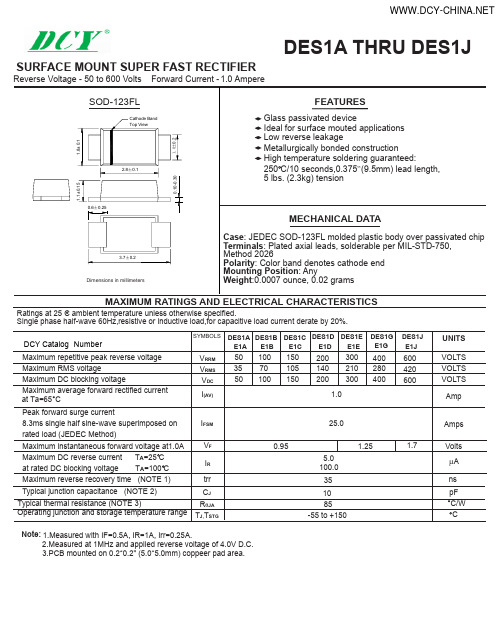
DES1J DES1GDES1EDES1D DES1C DES1B DES1A DCY Catalog DES1A THRU DES1JSURFACE MOUNT SUPER FAST RECTIFIERMAXIMUM RATINGS AND ELECTRICAL CHARACTERISTICSSYMBOLSUNITS 10070100400280400150105150600420600VOLTS VOLTS VOLTS AmpAmps Volts V RRM V RMS V DC I (AV)I FSM V F 1.025.01.25Maximum repetitive peak reverse voltage Maximum RMS voltageMaximum DC blocking voltageMaximum average forward rectified current Peak forward surge current8.3ms single half sine-wave superimposed on rated load (JEDEC Method)Maximum instantaneous forward voltage at1.0A Maximum DC reverse current T A =25 C at rated DC blocking voltage T A =100 C I R 5.0100.0A µRatings at 25 C ambient temperature unless otherwise specified.Single phase half-wave 60Hz,resistive or inductive load,for capacitive load current derate by 20%.E1B E1C E1D E1E E1JE1G Maximum reverse recovery time (NOTE 1)Typical junction capacitance (NOTE 2)C J pF Operating junction and storage temperature rangeNote:R θJA T J ,T STG8510-55 to +150CTypical thermal resistance (NOTE 3)°C/W 2.Measured at 1MHz and applied reverse voltage of 4.0V D.C.1.Measured with IF=0.5A, IR=1A, Irr=0.25A.3.PCB mounted on 0.2*0.2" (5.0*5.0mm) coppeer pad area.35ns 503550E1A trr 2001402003002103000.951.7Numberat Ta=65°CRATINGS AND CHARACTERISTIC CURVES DES1A THRU DES1J1.00.80.60.40.20 25 50 75 100 125 150 1750.01 0.1 1 10 1001001010.1REVERSE VOLTAGE,VOLTSt,PULSE DURATION,sec.FIG. 5-TYPICAL JUNCTION CAPACITANCEFIG. 6-TYPICAL TRANSIENT THERMAL IMPEDANCEFIG. 2-MAXIMUM NON-REPETITIVE PEAK FORWARDSURGE CURRENTFIG. 1- FORWARD CURRENT DERATING CURVEA V E R A G E F O R W A R D R E C T I F I E D C U R R E N T ,A M P E R E SJ U N C T I O N C A P A C I T A N C E , p FP E A K F O R W A R D S U R G E C U R R E N T ,A M P E R ES1001010.10.01PERCENT OF PEAK REVERSE VOLTAGE,%FIG. 4-TYPICAL REVERSE CHARACTERISTICSI N S T A N T A N E O U S R E V E R S E C U R R E N T ,M I C R O A M P E R E ST R A N S I E N T T H E R M A L I M P E D A N C E ,C /WAMBIENT TEMPERATURE, CFIG. 3-TYPICAL INSTANTANEOUS FORWARDCHARACTERISTICSI N S T A N T A N E O U S F O R W A R D C U R R E N T ,A M P E R E SINSTANTANEOUS FORWARD VOLTAGE,VOLTS0 0.4 0.8 1.2 1.6 1.8NUMBER OF CYCLES AT 60 HzThe cruve graph is for reference only, can't be the basis for judgment(曲线图仅供参考)!。

Features and Benefits• Illumination lamp lights up a wide area around V-grooves•Rugged and compact hand held design for demanding environmental conditions• Fast splice (13 sec) at low loss and fast heating (25 sec) for single fiber 1• Simple operation with fixed V-groove • Splicer is compatible with Seikoh Giken 2 and Diamond 3 SOCs • Internal battery charging•70 cycles for S123C/M4 V2 models with a single battery, and 160 cycles for S123M8/M12 v2 models with two batteries 4•Available for all METRO/LAN/FTTx fibers including ultra bend-insensitive fibers (e.g. EZ-Bend ® Fiber)OverviewWith its low profile and new super rugged body, the FITEL ® S123 Version 2 Series Fusion Splicer offers speedy operation for FTTx, LAN, backbone or long-haul installations. The lightweight, durable metal body frame and rubber protection corners provide robust protection, enabling use in challenging locations without compromising splicer performance. The S123 v2 Splicer is water resistant to IPX2 and dust resistant to IP5X.Product DescriptionA large battery capacity makes it possible to perform up to 70 cycles of splicing and heating for the S123C/M4 v2 models with a single battery, and 160 cycles for the S123M8/M12 v2 models with a dual battery configuration.Combining portability, power flexibility and field ruggedness, the S123 v2 Splicer delivers fast and consistent splicing with outstanding mobility and extreme ease-of-use. It also offers a splice-on-connector (SOC) solution.•Easy maintenance – Toolless electrode replacement/mirror free alignment system• Easy software upgrade via the Internet•Easily exchanged fiber holder systems (tight holder/fiber holder/SOC holder)•PC interface software to allow user management of splicing programs and results• Auto-start shrink sleeve oven feature • Improved GUI to further enhance ease-of-use• Large memory for storing data (2,000 splice data) and image (100 images)•RoHS compliantAuthorized Distributor of FITEL Products in the Americas1 By using semi-auto mode for splicing and pre-heating mode for heating2 Seikoh Giken is a registered trademark of SEIKOH GIKEN CO., LTD3 Diamond is a registered trademark of Diamond SA4By using semi-auto mode for splicing and regular mode for heatingRoHSIP525 Axis Shock2 | Under Tough EnvironmentsThe S123 v2 Fusion Splicer passed manufacturer testing based on criteria below 5 :• Drop resistant – 76 cm drops from 5 different angles• Water resistant – IPX2 rating drip proof6• Dust resistant – IP5X rating dust proof7S123C v2S123M4 v2S123M8 v2S123M12 v2Product Line-UpModel ApplicationS123C-A v2Splicing for single fiber (with soft case)S123C-B v2Splicing for single fiber (with hard case)S123M4-A v2Splicing for single to 4 ribbon fiber (with soft case)S123M4-B v2Splicing for single to 4 ribbon fiber (with hard case)S123M8 v2Splicing for single to 8 ribbon fiberS123M12 v2Splicing single to 12 ribbon fiber5 Above tests were performed at the manufacturer’s Furukawa Electric Co. Labs, and do not guarantee that the machine will be undamaged under these conditions.6 IPX2 rating drip proof means that the machine can be exposed to 3 mm/min drip from 4 different angles with 15° tilt for 2.5 min each and still functions.7 IP5X rating dust proof means that the machine can be exposed to dust particles with a diameter of 0.1 to 25 μm for 8 hours and still functions.Dust ResistantWater ResistantDrop ResistantApplicable Fibers SMF(ITU-T G.652), MMF(ITU-T G.651), DSF(ITU-T G.653), NZDSF(ITU-T G.655), BIF/UBIF (Bend insensitive fiber, ITU-T G.657)Cladding Diameter125 μmCoating Diameter250 to 900 μm for single fiber; 280 to 400 μm for ribbon (thickness) (S123M4, S124M8, S123M12) Fiber Cleave Length 5 to 10 mm (S123C); 10 mm (S123M4, S124M8, S123M12)Average Splice Loss SM: 0.05 dB, MM: 0.03 dB, DSF: 0.08 dB, NZDSF: 0.08 dBSplice Time Single fiber: 13 seconds; Ribbon fiber: 15 secondsHeat Time6Single fiber: 25 seconds (S922: 40 mm sleeve, S921: 60 mm sleeve) (Preheat mode) 7 (S123C, S124M4) Ribbon fiber: 35 seconds (S924: 40 mm sleeve) (Preheat mode) 8Splice Programs Max. 150 Heat Programs Max. 18 Automatic Heating Start Available Applicable Sleeves20/40/60 mmFiber Holding Tight holder (Loose tube applicable) or Fiber Holder System (S213C) Fiber holder system (S123M4, S124M8, S123M12)Tension Test 1.96 NReturn Loss of Splice60 dB or moreFiber Image Magnification58X (S123C), 48X (S123M4), 28X (S123M8), 20X (S123M12)Splice Memory Max. 1500 splices (S123C, S123M4); Max. 1000 splices (S123M8, S123M12)Image Capture Capacity Last 100 images to be automatically captured + Up to 24 images to be stored permanentlyDimension S123, S123M4: 127W × 199D × 81H mm (not including shock absorber) 159W × 231D × 104H mm (including shock absorber)S123M8, S123M12: 127W × 199D × 105H mm (not including shock absorber) 159W × 231D × 130H mm (including shock absorber)Weight S123C, S123M4: 1.4 kg (without battery), 1.6 kg (with S943B battery)S123M8, S123M12: 1.6 kg (without battery), 2.0 kg (with two S943B batteries)Monitor 3.5” color LCD monitorData Output USB ver.2.0 miniDisplaying Language20 languages (e.g. English, Spanish, Japanese, Chinese)Battery Capacity Typical 70 splice/heat cycles with S943B battery (S123C, S124M4) 9Typical 160 splice/heat cycles with two S943B batteries (S123M8, S124M12) 10Wind Protection Max. wind velocity of 15 m/sOperating Temperature-10 to + 50 °C (without excessive humidity)Storage Temperature-40 to +60 °C (without excessive humidity)Power Source AC Input 100 to 240 V (50/60 Hz), DC Input 11 to 17 V without any change of hardware8The first heating after turning on the power can be longer that usual heating time9 The number of the splicing and heating cycles the machine can produce using a fully charged battery at room temperature of 20° C, semi-auto mode for splicing and regular mode for heating. Depending on the condition of the batteries and operation environment, the number can vary.10T he number of the splicing and heating cycles the machine can produce using a two fully charged battery at room temperature of 20° C, semi-auto mode for splicing and regular mode for heating. Depending on the condition of the batteries and operation environment, the number can vary.S123 v2 Fusion Splicers | 3Compatible with Spice-on-Connectors (SOC)FITEL Splicer SOC PartnersCONNECTORS4 | Standard PackageItem P/N QuantityS123C-A S123C-B S123M4-A S123M4-B S123M8S123M12 1.) S123C v2 Main body S123-C-A-0001-V211————1.) S123M4 v2 Main body S123-M4-A-0003-V2——11——1.) S123M8 v2 Main body S123-M8-A-0003-V2————1—1.) S123M12 v2 Main body S123-M12-A-0003-V2—————12.) Soft Carrying Case SCC-011—1———3.) Hard Carrying Case HCC-01————113.) Hard Carrying Case HCC-02—1—1——4.) Battery Pack S943B1111 1 or 2 1 or 25.) Spare Electrodes S9691111116.) AC Adaptor for S123 v2S976A1111117.) AC Cable Cord—1111118.) Electrode Sharpener D51111111119.) Cleaning Brush VGC-0111111110.) Fiber Reformer (4)S122-X-A-0007—— 1 pair 1 pair——10.) Fiber Reformer (8/12)S122-X-A-0008———— 1 pair 1 pair User Manual—111111◆♦⌧⍓❝❝Cleaning Brush⍓Spare ElectrodesElectrode Sharpener❞❞Fiber ReformerItemP/N Quantity 1.) Soft Carrying Case SCC-0112.) Battery ChargerS958C 13.) AC Adaptor for S958C S977A 14.) Cooling Tray CTX-0115.) Angled Stand AGS-0116.) Working Belt WBT-0117.) USB CableUSB-0118.) Car Cigarette Cable CDC-0119.) Tripod AdaptorTPA-01110.) Tight Holder16 mm Cleave length 10 mm Cleave length S712T-016 S712T-010 1 pair 1 pair 11.) Fiber Holder160 μm coated fiber 250 μm coated fiber 500 μm coated fiber 900 μm coated fiberLoose Tube Fiber (left side) Loose Tube Fiber (right side)S712S-160S712S-250S712S-500S712S-900 S712S-LT-L S712S-LT-L1 pair 1 pair 1 pair 1 pair 1 pair 1 pair12.) SOC Holders <For Ferrule>Seiko Giken FC/SC connector (9 mm)Seiko Giken FC/SC connector (5 mm)Seiko Giken LC connector (9 mm)Seiko Giken LC connector (5 mm)Diamond E-2000/F-3000 connector <For Cordage>Seiko Giken Cordage (5 mm)Seiko Giken Cordage (9 mm)Diamond Cordage (5 mm)S712C-SGS9-L S712C-SGS5-L S712C-SGL9-L S712C-SGL5-L S712C-DM25-L S712C-SGC5-R S712C-SGC9-R S712C-DMC5-R 11111 11 1<Tool>Diamond Mount WTX-011 Smart FuseSoftware Interface for MachineSF-011S123 v2 Fusion Splicers | 5CategoryCodeDescriptionX Fiber Holder Type12316 mm Tight Holder S712T-01610 mm Tight Holder S712T-010Fiber Holder System Y . Number of Battery Packs (S943)01*2*Without battery pack 1 pack 2 packs* With 1 S958 battery charger and 1 S977 AC adapterAngled Stand in Action⍓Working Belt in ActionWorking Belt asShoulder Pack◆♦⌧⍓❝❞S123 v2 Fusion Splicers | 6。
小体积、低成本、简单电路日本石塚CRD恒流二极管应用介绍应用采用超小体积SOD-123FL封装(类似电阻1206封装)的日本石塚CRD恒流二极管适用于多个小功率LED串联电路,输入电压220V或110V,亦可用于低压电路,每串串联个数可达92pcs(LED Vf =3.2V);该系列CRD应用时不需其它外围辅助元件,电路简单稳定、成本低,只需经市电整流滤波,再加上CRD即可;普遍适用于T5、T8 LED日光灯管、LED灯条模组、LED射灯、LED台灯、LED球泡灯及其它LED照明装饰类产品。
特点* 小体积、低成本◆采用超小SOD-123FL封装,狭小的空间也完全可以适用;* 高稳定性◆即使输入电压及LED VF值变动也可提供恒定电流输出;* 高效率◆串灯合适,效率可高达90%以上;* 负温度系数特性◆环境温度升高,CRD抑制输出电流,保护LED。
备注:(低厚度SOD-123FL封装,SOD-123FL封装器件可直接替代电路板中的SOD-123(JEDEC DO219)封装器件。
SOD-123FL封装的瓦特/ mm2 热性能比SOD-123提高达149%,比SMA提高达90.5%,比PowerMite提高达26.5%。
SOD123FL厚度(最大为1mm)比标准SOD123封装低25%或以上,适宜电路板空间受限的便携应用。
SOD-123FL封装的引脚结构和线夹设计,允许低正向电压。
附带线夹的内部设计比引线粘结封装具有更好的浪涌电流能力,适合瞬态电压抑制应用)。
共9页之第1页常用恒流二极管主要参数型号恒流范围值(MA)最高耐压(V)恒流启动电压(V)最佳压降6-20V S-562T 5.0-6.0 100 4.56-20V S-103T 8.0-12.0 50 3.56-15V S-123T 9.0-14.0 50 3.86-15V S-153T 12.0-15.0 50 4.36-15V S-183T 15.0-18.0 50 4.6常规应用电路①常规220V/100V单串应用电路共9页之第2页②常规220V /100V多串应用电路备注:常规应用图中参数仅供参考,88PCS LED/串是在LED电流为20MA/VF=3.2V的情况所采用的串法,实际应用需依据所采用电解电容和所要求的LED电流及此时的VF值来调整串数。