303b红外测温仪产品说明
- 格式:doc
- 大小:100.50 KB
- 文档页数:3
标题:探秘HP303B气压计数据手册1. 引言近年来,气压计作为一种重要的大气观测设备,被广泛应用在气象、环境监测、航空航天等领域。
HP303B气压计作为一款性能优异的气压传感器,备受关注。
本文将从数据手册的角度出发,深入探讨HP303B气压计的技术特点和应用价值。
2. 技术特点HP303B气压计采用了先进的MEMS技术,具有高精度、低功耗、温度补偿等特点。
在数据手册中,可以详细了解其工作原理、接口定义、电气特性等技术参数,深入理解其技术特点。
3. 应用价值数据手册中还介绍了HP303B气压计的应用范围和场景,包括气象观测、气候监测、无人机导航等领域。
通过数据手册的详细介绍,可以更好地了解HP303B气压计在各种应用场景下的性能表现和优势。
4. 深度评估通过对HP303B气压计数据手册的深入研读和分析,可以更全面地了解其技术特点和应用价值。
本文也将结合个人的观点和理解,对其优势和劣势进行评估,为读者提供更多维度的参考。
5. 个人观点作为一款先进的气压传感器,HP303B在高精度和低功耗方面表现突出,但在特殊环境下的稳定性和耐用性还有待提高。
对于不同的行业应用来说,HP303B都有着广阔的市场前景,但在实际使用过程中需要根据具体需求进行精细化调节和优化。
6. 总结与回顾通过本文的探讨,我们对HP303B气压计的技术特点和应用价值有了更深入的了解。
在今后的使用和研究过程中,我们可以更加灵活地应用这些知识,为相关领域的发展和创新贡献自己的力量。
结尾语:如此看来,通过数据手册的深入解读,我们对HP303B气压计的技术细节和应用情况都有了清晰的认识。
希望本文能够对大家有所启发,也欢迎各位多提宝贵意见。
HP303B气压计作为一款先进的气压传感器,具有高精度、低功耗等技术特点,广泛应用于气象、环境监测、无人机导航等领域。
本文将从数据手册的角度出发,深入探讨HP303B气压计的性能特点、应用场景及其在不同行业中的优势和劣势。
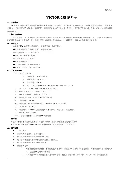
VICTOR303B说明书一、产品简介VICTOR303B是一种专业手持式非接触红外线测温仪,使用简单,设计严谨,测量准确度高,测温量程范围宽等特点。
它具有激光瞄准,带背光源LCD显示器,超温报警,发射率可调及自动关机功能。
使用时,只须将探测窗口对准物体,就能快速准确地测量物体的温度。
二、基本工作原理一切温度高于绝对零度物体,均会依据其本身温度的高低发射一定比例的红外辐射能量。
辐射能量的大小及按波长的分布与它的表面温度有着十分密切的关系。
依据此原理,能准确地测定物体的红外发射能量,便得出被测物体的准确温度。
三、产品特点◆采用HEIMANN红外测温探头,测量精度高,性能更稳定;◆具有测量温度高(阀值可设置)、声音提示功能;◆背光型液晶(LED)数字显示;◆华氏、摄氏两种模式选择;◆发射率0.1~1.00可调;◆内置激光瞄准器;◆自动关机功能(节省电池耗费);◆体积小巧、结构合理、操作方便。
四、主要技术指标(一)、正常工作条件:1.环境温度: 10℃~30℃;2.储存温度: -10℃~40℃3.相对湿度:≤90%;4.电源:一只9V电池(NEDA1604/6F22或同等型号);(二)、基本尺寸: 97mm×43mm×160mm(长×宽×高)。
(三)、重量(净重):125g(不含电池)。
(四)、LCD显示分辨力(精确度):0.1℃/℉。
(五)、测量范围:-20℃~550℃(-4℉~1022℉)。
(六)、消耗功率:≤50mw。
(七)、测量误差:±2.0℃或±2%(在0℃-25℃为±3.0℃)取大值。
(八)、测量时间:≤0.5秒。
(九)、测量距离:D:S=12:1(测量距离与物体目标比,测量条件:真空介质)。
(十)、自动关机时间:60秒。
(十一)、安全设计标准:符合欧洲CE安全规范。
EMC/RFI在强度3伏特/米的射频电磁场中,可能影响读数,但是仪器性能不会受到永久影响。
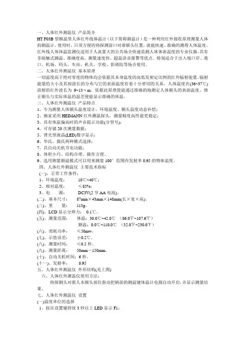
一、人体红外测温仪产品简介HT-F03B型额温型人体红外线体温计(以下简称额温计)是一种利用红外接收原理测量人体的测温计。
使用时,只须方便的将探测窗口对准额头位置,就能快速、准确的测得人体温度。
红外线人体体温监测仪适用于人流量大的公共场合快速监测人体体表温度的专业仪器。
具有非接触式测温、准确度高、测量速度快、超温语音报警等优点。
特别适合于出入境口岸、港口、机场、码头、车站、机关、学校、影剧院等场合使用。
二、人体红外测温仪基本原理一切温度高于绝对零度的物体均会依据其本身温度的高低发射定比例的红外辐射能量。
辐射能量的大小及其按波长的分布与它的表面温度有着十分密切的关系。
人体温度在(36~37℃)放射的红外波长为9~13чm。
依据此原理便能通过准确的地测定人体额头的表面温度,修正额头与实际体温的温差便能显示准确的体温。
三、人体红外测温仪产品特点1、专为测量人体额头温度设计,环境温度、额头温度动态补偿;2、独家采用HEIMANN红外测温探头,测量精度高性能更稳定;3、具有体温偏高时的声音提示功能(分型号);4、可存储20次测量数据;5、背光型液晶(LED)数字显示;6、华氏、摄氏两种模式选择;7、具自动关机节电功能;8、体积小巧、结构合理、操作方便。
9、选用测量额温模式可以用来测量100°范围内发射率0.95的物体温度。
四、人体红外测温仪主要技术指标(一)、正常工作条件:1、环境温度:10℃~40℃;2、相对温度:≤85%;3、电源:DC3V(2节AA电池)。
(二)、基本尺寸:87mm×43mm×148mm(长×宽×高)。
(三)、重量:113g。
(四)、LCD显示分辨力:0.1℃。
(五)、测量范围:体温:30.0℃~42.0℃(86.0℉~107.6℉)额温:0.0℃~110.0℃(32.0℉~230.0℉)(六)、消耗功率:≤50mw。
(七)、示值误差:±0.2℃。
VICTOR303B说明书一、产品简介VICTOR303B是一种专业手持式非接触红外线测温仪,使用简单,设计严谨,测量准确度高,测温量程范围宽等特点。
它具有激光瞄准,带背光源LCD显示器,超温报警,发射率可调及自动关机功能。
使用时,只须将探测窗口对准物体,就能快速准确地测量物体的温度。
二、基本工作原理一切温度高于绝对零度物体,均会依据其本身温度的高低发射一定比例的红外辐射能量。
辐射能量的大小及按波长的分布与它的表面温度有着十分密切的关系。
依据此原理,能准确地测定物体的红外发射能量,便得出被测物体的准确温度。
三、产品特点◆采用HEIMANN红外测温探头,测量精度高,性能更稳定;◆具有测量温度高(阀值可设置)、声音提示功能;◆背光型液晶(LED)数字显示;◆华氏、摄氏两种模式选择;◆发射率0.1~1.00可调;◆内置激光瞄准器;◆自动关机功能(节省电池耗费);◆体积小巧、结构合理、操作方便。
四、主要技术指标(一)、正常工作条件:1.环境温度: 10℃~30℃;2.储存温度: -10℃~40℃3.相对湿度:≤90%;4.电源:一只9V电池(NEDA1604/6F22或同等型号);(二)、基本尺寸: 97mm×43mm×160mm(长×宽×高)。
(三)、重量(净重):125g(不含电池)。
(四)、LCD显示分辨力(精确度):0.1℃/℉。
(五)、测量范围:-20℃~550℃(-4℉~1022℉)。
(六)、消耗功率:≤50mw。
(七)、测量误差:±2.0℃或±2%(在0℃-25℃为±3.0℃)取大值。
(八)、测量时间:≤0.5秒。
(九)、测量距离:D:S=12:1(测量距离与物体目标比,测量条件:真空介质)。
(十)、自动关机时间:60秒。
(十一)、安全设计标准:符合欧洲CE安全规范。
EMC/RFI在强度3伏特/米的射频电磁场中,可能影响读数,但是仪器性能不会受到永久影响。
BWD3K320B型干式变压器微电脑控制仪使用说明书桓仁温度测控仪表厂提示:为避免变压器初次通电时,产生的瞬时高压及拉孤现象,请在变压器通电正常运行正常后,再接通温控器电源。
一、概述BWD_3K320B型电脑温控器是我厂为风冷干式电力变压器可靠运行而设计的新一代多功能型电脑温度控制器。
利用预埋在干式电力变压器三相绕组线包中拓三只Pt100铂热电阻来检测干式电力变压器线包的温升,并根据温升自动控制冷动风机的启停、超温报警直至超高温跳闸以保证干式电力变压器的安全运行。
由于采用目前先进的RISC单片计算机并结合先进的I2C存储与调整技术,根据JB/T7631_94标准设计而成,使得温控器具有结构简单,运行可靠抗干扰能力极强的特点。
同时温控器还具有“黑匣子”功能,可记录停电前三个绕组线包的温度及本机的工作状态. 其主要特点有:▲先进的电路设计技术,可更有效抑制零点漂移.同时机内全部采用低温度系数元器件,能有效的抑制温度漂移。
▲先进的抗干扰设计技术,温控器采用先进的PCB设计,模似滤波技术与多重数字滤波技术相结合,对电源瞬变,共模,串模及空间射频等干扰均有极强的抑制能力.▲RISC单片计算机内置WATCHDOG和上、掉电检电路,使得温控器在各种条件下均能正常工作而不需另设复位键。
避免了工作人员靠近变压器主体操作对人身安全造成伤害的危险. ▲完善的检测保护功能,能有效地判断传感器短路及开路故障.当温控器因传感故障不能检测温度时将强迫风机启动以保障变压器的安全,同时机内声光报警,接通报警触点远传故障信息以便及时外理.▲风机检测保护功能。
为避免风机长时期不启动而锈蚀堵转,温控器设有定时启动风机功能。
同时通过面板的轻触键也可启动风机以检测风机功能。
▲温控器可通过模似输入温度值而检测温控的控制功能. ▲操作简便,用户通过温控器面板上的轻触键即可设置各种控制温度参数.智能化设置方法能自动判断设置的温度范围。
设置好的温度参数停电后也不会丢失。
红外线测温仪的性能及使用介绍红外线测温仪是一种用于测量目标表面温度的仪器,口袋里的温度计就是一种红外线测温仪。
其原理基于物体辐射热学的基本原理,即所有物体温度高低都会发出不同程度的红外辐射,利用红外线测温仪可以将这种辐射转换为温度值。
性能介绍测温范围红外线测温仪的测温范围通常根据不同的型号会有所不同。
一般来说,它们可以测量的范围在-50℃至+650℃之间,而高端产品甚至能够达到更宽泛的范围。
但是,对于极低或极高温度的测量仍然需要特殊的定制。
精度通常来说,红外线测温仪的精度达到小数点后一位甚至是两位。
然而,这种仪器的精度受到很多因素的影响,比如仪器自身的扰动、环境温度、湿度和气流等等。
因此,在使用红外线测温仪时,需要考虑到这些因素,避免误差。
距离比距离比是指测量距离与測量点大小之比。
这个比例对于红外线测温仪的精度至关重要。
通常来说,红外线测温仪的距离比是8:1或12:1左右,也就是说,如果在距离1m处测量,其测量点大小只有10cm的左右。
解析度解析度是表示传感器能够读取的最小温度变化值。
通常来说,红外线测温仪的解析度为0.1至0.2摄氏度之间,高端产品可以达到更高的分辨率。
然而,如果目标温度不是非常稳定,解析度可能会下降。
响应时间响应时间是指传感器从测量目标获取信号到显示其真实温度所需的时间。
一般来说,红外线测温仪的响应时间是0.1秒至1秒不等。
使用方法准备工作在使用红外线测温仪之前,需要进行一些准备工作。
首先,确定测量的对象和红外线测温仪的距离比。
然后,清洁和干燥测量表面,避免表面有杂质影响测量结果。
最后,选择与目标温度相匹配的测量范围。
测量过程在实际的测量过程中,需要将红外线测温仪对准目标,在屏幕上读取温度。
在屏幕底部经常会有最小、最大和平均温度等指标显示。
如果需要更好的精度,可以使用一些内置的计算程序来调整显示的数值。
如果测量结果出现问题,可以将测量距离、环境温度和湿度等因素控制在可容忍的范围。
酒精传感器(型号:MQ303B)使用说明书版本号:1.4实施日期:2017-9-20郑州炜盛电子科技有限公司Zhengzhou Winsen Electronic Technology Co., Ltd声明本说明书版权属郑州炜盛电子科技有限公司(以下称本公司)所有,未经书面许可,本说明书任何部分不得复制、翻译、存储于数据库或检索系统内,也不可以电子、翻拍、录音等任何手段进行传播。
感谢您使用本公司的系列产品。
为使您更好地使用本公司产品,减少因使用不当造成的产品故障,使用前请务必仔细阅读本说明书并按照所建议的使用方法进行使用。
如果您没有依照本说明书使用或擅自去除、拆解、更换传感器内部组件,本公司不承担由此造成的任何损失。
您所购买产品的颜色、款式及尺寸以实物为准。
本公司秉承科技进步的理念,不断致力于产品改进和技术创新。
因此,本公司保留任何产品改进而不预先通知的权力。
使用本说明书时,请确认其属于有效版本。
同时,本公司鼓励使用者根据其使用情况,探讨本产品更优化的使用方法。
请妥善保管本说明书,以便在您日后需要时能及时查阅并获得帮助。
郑州炜盛电子科技有限公司半导体气体传感器系列MQ303B 酒精传感器产品描述MQ303B 气体传感器所使用的气敏材料是在清洁空气中电导率较低的半导体材料。
当传感器所处环境中存在酒精蒸气时,传感器的电导率随空气中酒精气体浓度的增加而增大。
使用简单的电路即可将电导率的变化转换为与该气体浓度相对应的输出信号。
传感器特点 高灵敏度、快速响应恢复、长寿命、低功耗、低成本、外型小巧应用 对酒精具有高的灵敏度和快速的响应性能,适于便携 式酒精探测器和汽车燃火系统等等。
技术指标 表1气体传感器敏感部分是一个微型球体,内嵌加热丝和金属电极,这种敏感元件安装在有防爆功能的双层100目不锈钢网的金属壳内。
(如图1)产品型号 MQ303B 产品类型 半导体气体传感器标准封装 金属封装 检测气体 酒精 检测浓度 20-500ppm 酒精 标准电路条件加热电压 V H 0.9V ± 0.1V AC or DC回路电压 V c ≤6V DC 负载电阻 R L 可调加热电阻 R H 4.0Ω ± 0.5 Ω(室温)加热功率P H ≤ 140 mW 标准测试条件下传感器特性零点 V 0 0.01-0.45V 灵敏度 V S 1.0-2.5V(125ppm 酒精) 浓度斜率α≤0.6(R 300ppm /R 50ppm 酒精)标准测试条件温度、湿度20℃±2℃; 55%±5%RH 标准测试电路 Vc:3.0 V ±0.1 V DC ; V H : 0.9 V ±0.1 V DC预热时间不少于48小时图1 元件外形结构图基本测试电路传感器特性图3 元件灵敏度特性曲线灵敏度特性图反映了元件电阻和气体浓度之间的关系。

Model UT301A/B/CUT302A/B/CUT303A/B/C OPERATING MANUALTitlePage55577910101011111215151515161616171Table of ContentsIntroductionContacting Uni-Trend Safety Information Features DisplayButtons and ConnectorHow the Thermometer works.Operating the ThermometerLocating a Hot or Cold Spot Distance and Spot Size Field of View Emissivity Trigger LockSwitching o C/ oF HOLDTypical MeasurementsTesting Contactors (Starters)Testing Enclosed RelaysTesting Fuses and Buss Connections Testing Electrical Connections2171819202021212121212222232324242424Table of ContentsTitlePageScanning Walls for Air Leaks or Insulation Deficiencies Testing BearingsTesting Belts and SheavesChecking Hydronic Radiant Heat Applications Measuring Grille, Register, or Diffuser Discharge TemperatureChecking for Blockage in Air-To-Air Evaporators or Condensers MaintenanceChanging the Battery Cleaning the Lens Cleaning the Housing Troubleshooting CE Certification Specifications InfraredLaser Electrical PhysicalEnvironmental3691322Table Title PageList of Tables1. Symbols2. Buttons and Connector3. Surface Emissivity4. Troubleshooting47789101111Figure TitlePageList of Figures1 Symbols and Safety Markings2 Infrared Thermometer3 Thermometer Display4 Buttons and Connector5 Locating Hot or Cold Spot6 Distance and Spot Size 7Field of View5To contact Uni-Trend. call (852) 2950 9168 or visit Uni-Trend web site at IntroductionThe Model UT301A/B/C, UT302A/B/C and UT303A/B/C Infrared Thermometer (hereafter, the “Thermometer”)can determine the surface temperature by measuring the amount of infrared energy radiated by the target’s surface. They have different distance to spot (D:S) figure and different temperature range, details see the contents.The Thermometers are non-contact infrared thermometer with low consumption design so that they can be used for a longer time, which can solve the frequently changing battery and low battery issues during measurement.Intelligent design can make measurement easier and quicker. The Thermometer can intelligently select battery or USB power source.This Manual uses UT303A/B/C as illustration.Contacting Uni-TrendSafety Information6Table 1 and Figure 1 show various symbols and safety markings that are on the Thermometer and in this manual.Table 1. Symbolsl than actual temperature measurements.Do not use in a manner not specified by this manual or the protection supplied by the equipment may be impaired.CautionTo avoid damaging the thermometer or the equipment under test protect them from the following:l l l l EMF (electro-magnetic fields) from arc welders, induction heaters, etc.Static electricity.Thermal shock (caused by large or abrupt ambient temperature changes – all 30 minutes from the Thermometer to stabilize before use).Do not leave the Thermometer on or near objects of high temperature.Figure 1. Symbols and Safety MarkingsFeaturesThe Thermometer includes:l l l lll l Single-spot Laser SightingIntelligent USB power sourceBacklit DisplayTwo level white colour Backlit Display (when usingUSB power up, this feature will be on automatically).Current Temperature Plus MIN, MAX, DIF, AVGTemperature Displays/Easy Emissivity SelectorTrigger LockedlllDegree Celsius and Fahrenheit TemperatureSelectableTripod mountOne 9V BatteryThermometer features are shown in Figure 2.DisplayThe primary temperature display reports the current orlast IR temperature read until the 8-second hold timeelapses.Figure 2. Infrared Thermometer7The secondary temperature display reports a choice of Array maximum, minimum, difference between maximum andminimum temperature or average value.You can toggle through the maximum, minimum,difference and average IR temperatures anytime thedisplay is on. The MAX, MIN, DIF and AV temperaturesare constantly calculated and updated when the triggeris pressed. After the trigger is released, the MAX, MIN,DIF and AV temperatures are held for 8 seconds.Figure 3. Thermometer Display89Buttons and ConnectorTable 2. Buttons and Connector10How the Thermometer WorksInfrared thermometers measure the surface temperature of an opaque object. The Thermometer’s optics sense infrared energy, which is collected and focused onto a detector. The Thermometer’s electronics then translate the information into a displayed temperature reading which appears on the display. The laser is used for aiming purposes only.Operating the ThermometerThe Thermometer turns on when you press the trigger. The Thermometer turns off when no activity is detected for 8 seconds.To measure temperature, aim the Thermometer at the target, pull and hold the trigger. Release the trigger to hold a temperature reading.Be sure to consider distance-to-spot size ratio and filed of view. The laser is used for aiming only.To find a hot or cold spot, aim the Thermometer outside the target area. Then, slowly scan across the area with an up and down motion until you located the hot or cold spot. See Figure 5.Figure 5. Locating Hot or Cold Spot11As the distance (D) from the target being measured increases, the spot size (S) of the area measured by the unit becomes larger. The spot size indicates 90%encircled energy. The maximum D:S is obtained when the Thermometer is 600mm (60 in) form the target resulting in a spot size of 20mm (2 in). See Figure 6.Figure 6. Distance and Spot SizeMake sure that the target is larger than the spot size.The smaller the target, the closer you should be to it.See Figure 7.Figure 7. Field of ViewEmissivity describes the energy-emitting characteristics of materials. Most organic materials and painted or oxidized surfaces have an emissivity of about 0.95.If possible, to compensate for inaccurate readings that may result from measuring shiny metal surfaces, cover the surface to be measured with masking tape or flat black paint (<150 o C / 302 o F) and use the high emissivity setting. Allow time for the tape or paint to reach the same temperatures as the surface beneath it. Measure the temperature of the tape or painted surface.If you cannot use paint or use tape, then you could improve the accuracy of your measurements with the emissivity selector. Even with emissivity selector, it can be difficult to get a completely accurate infrared measurement of a target with a shiny or metallic surface. The Thermometer allows you to adjust the unit’s emissivity for the type of surface before measured. Refer to Table 2. But it is only a typical case. You could base on your own case and materials to have different setting.To adjust values for emissivity, follow the below procedure:1.2.3.Press SET to select emissivity set up, icon E on the display is blinking. The Thermometer steps through emissivity set up, trigger lock and switching o C / o F.Press to increase the value by 0.01 or press and hold to access quick setting. The maximum value is 1.00.Press to decrease the value by 0.0 or press and hold to access quick setting. The minimum value is 0.10.12Table 3. Surface EmissivityMeasure Surface METALSAluminumOxidizedAlloy A3003OxidizedRoughenedBrassBurnishedOxidizedCopperOxidizedElectrical Terminal Blocks HaynesAlloyInconelOxidizedSandblasted Electoropolished Switch Setting0.2-0.40.30.1-0.30.30.50.4-0.80.60.3-0.80.7-0.950.3-0.60.15Measure SurfaceIron CastOxidizedUnoxidizedMoltenIron WroughtDullLeadRoughOxidizedMolydbenumOxidizedNickelOxidizedPlatinumBlackSteelCold-RolledSwitch Setting0.6-0.950.20.2-0.30.90.40.2-0.60.2-0.60.2-0.50.90.7-0.913Table 3. Surface EmissivityMeasure Surface IronOxidizedRustedNON-METALS Asbestos AsphaltBasaltCarbon Unoxidized Graphite Carborundum CeramicClayConcreteCloth Switch Setting0.5-0.90.5-0.70.950.950.70.8-0.90.7-0.80.90.950.950.950.95Measure SurfaceGround SheetPolished SheetZincOxidizedGlassPlateGravelGypsumIceLimestonePaper (any colour)PlasticOpaqueSoilWaterWood, (natural)Switch Setting0.4-0.60.10.10.850.950.8-0.950.980.980.950.950.9-0.980.930.9-0.9514T o lock or unlock the trigger, follow the below procedures: 1. Press SET to select trigger lock setting, the is blinking.2. Press to select ON or OFF.When the trigger is locked, the Thermometer is on for continues measurement, there is no need to pull the trigger.When the trigger is unlocked, user needs to pull the trigger for measurement. When you release the trigger, the Thermometer will keep hold the measurement result automatically.1. Press SET to choose o C / o F selection mode,2. Press to select o C or o F.The display will remain activated 8 seconds after the trigger is released. HOLD appears in the upper middle of the display. When the trigger is pulled again, the Thermometer will begin measuring in the last function selected.Typical MeasurementsThis section describes a variety of measurements often performed by technicians.User could select to turn on or off the backlight and laser whenever you are making readings with the Thermometer. But if you are using USB to power up the Thermometer, the two levels white colour backlight will be on automatically.Relatively high emissivity normally means emissivity setting of about 0.95.Relatively low emissivity normally means emissivity setting of about 0.30.When user cannot identify the emissivity of the object llll15to be measured, user could cover the surface to be measured (temperature >150o C) with black electric tape (emissivity of about 0.95). Allow time for the tape to reach the same temperature as the object to be measured. Measure and record the temperature of the tape.Target the Thermometer to the object to be measured, adjust the emissivity setting to make it as the same temperature as the tape. At this time, the Thermometer emissivity setting is close to the emissivity of the object to be measured, measurement could be started.1. 2. 3. 4.Press SET to select emissivity. Press / to selectrelatively low emissivity for bright contacts, or 0.7mid level for darkened contacts.Press MODE to select MAX.Measure line and load side of one pole withoutreleasing trigger.A temperature difference between the line and loadsides of a pole indicate increased resistance ofone point and a contactor may be failing.1.2.3.4.5.Press SET and then press / to set emissivity torelatively low for uninsulated connectors or relativelyhigh for plastic encased relays or for bakeliteenclosed relays or insulated connectors.Press MODE to select MAX.Start to scan.Measure the relay casing, looking for hot spots.Measure electrical connections on relay terminalslooking for hot spots.1.2.3.4.5.Press SET and then press / to set emissivity torelatively high for paper covered fuse body orinsulated connections.Press MODE to select MAX.Scan the paper covered length of fuse.Without releasing the trigger, scan each fuse.Unequal temperatures between fuses may indicatevoltage or amperage imbalance.Press SET and then press / to set emissivity torelatively low, for metal fuses and caps and insulated16176.7.buss connections.Press MODE to select MAX.Scan each end cap on each fuse/Press SET and then press / to set emissivity torelatively low for uninsulated connectors or buss connections or relatively high for insulated connections.1.Scan the conductor, moving toward direction ofelectrical connector (quick connect, wire nut, buss connection, or lug).2.Turn off heating, cooling, and blower.Press SET to select emissivity. Press / to selectemissivity relatively high for painted surfaces or window surfaces.Press MODE to select MIN when opposite side ofwall is at lower temperature and or select MAX when opposite side of wall is at higher temperature.Measure an interior partition wall surface temperature.Do not release the trigger. Record this temperature as your baseline (or benchmark) for a “perfectly”insulated wall.Face the wall to be scanned. Stand 1.5m away toscan a 5cm spot on the wall.Scan horizontal rows of wall from top to bottom, orhorizontal rows of ceiling from wall to wall. Look for greatest deviations from baseline temperature to identify problems. This completes the insulation test scan.1.2.3.4.5.6.Turn on the blower (no heat, no cooling) and retest. If test results with the blower on are different than results with the blower off, this may indicate air leaks inconditioned envelope walls. The air leaks are caused by duct leaks that create a pressure differential across the conditioned space envelope.WarningTo avoid injury when testing bearings:Do not wear loose clothing, jewelry, or anything around neck when working around moving parts such as motors, belts, blower, and fans.Make sure an electrical disconnect is within reach and operating correctly and freely.Do not work alone.Press SET and then press / to select relatively high emissivity.Press MODE to select MAX.Enable motor and allow it to reach steady state operating temperatures.Disable the motor if possible.Measure the two motor bearing temperatures Compare the two motor bearing temperatures.Unequal temperatures or a high temperature can indicate a lubrication or other bearing problem that is resulting from excess friction.Repeat the sequence for the blower bearings. 1.2.3.4.5.6.7.l l l1819Press SET and then press / to select relativelyhigh emissivity.Press MODE to select MAX.Enable the motor and allow it to reach a steadystate operating temperatures.Aim the Thermometer at the surface to be measured.Start recording temperatureSlowly move the Thermometer up the belt towardsecond sheave.1.2.3.4.5.6.If belt is slipping, sheave temperature will be high from friction.If belt is slipping, belt temperature will remain high between sheaves.If belt is not slipping, belt temperature will reduce between sheaves.If inner surfaces of sheaves are not a true “V”shape, this indicates belt slippage and will continue to operate at elevated temperatures until sheave is replaced.Sheaves must be properly aligned (include “pitch& yaw”) for belt and sheaves to operate at appropriate temperatures. A straight edge or taut string, can be used to check alignments.Motor sheave should operate at a temperature consistent with blower sheaves.If motor sheave is at a higher temperature at motor shaft than at outer circumference, belt is probably not slipping.If outer circumference of sheave is at higher temperature than sheave at motor shaft, then belt is probably slipping and sheaves may be misaligned.l l l l l l l l1. 2. 3.4.Press SET and then press / to select relatively high emissivity.Press MODE to select MAX.To locate radiant heat tubes in floor, temporarily elevate the loop temperature to create hotter spots for identifying tubing runs.Before releasing trigger, press MODE to toggle between MIN, MAX, DIF floor temperatures and record the temperature for future comparison and trending under similar conditions.Radiant heat tubes in the floor will normally run parallelto the outside walls. Starting at the floor wall juncture, scan parallel to the wall while moving into the room away from the wall. Parallel to the outside wall you should find parallel isothermal rows indicating the location of heat tubes below the surface. Perpendicular to the outside wall, you should find rising and falling temperatures at equal distances. High temperatures indicate you are scanning a heat tube beneath the floor surface, low falling temperatures indicate a space between the heat tubes.1.2.3.4.5.Press SET and then press / to select relatively high emissivity.Aim the Thermometer at the discharge air grille, register, or diffuser.Measure discharge temperature.Release trigger to freeze the temperature reading for 8 seconds and record this temperature.Grille, register, or diffuser temperature should be equivalent to discharge temperature at the air handler.201. 2. 3. 4. 5. 6.Remove panels to gain access to coil return bendsor hairpins.Press SET and then press / to select relativelyhigh emissivity for copper tube.Start the refrigeration system.Aim the Thermometer at coil turn bends/hairpins.Start recording temperature.Take temperature of each return bend/hairpin.All evaporator return bends/hairpins should beat or slightly above evaporator saturationtemperature from the pressure/temperaturechart.All condenser return bend/hairpins should beat or slightly less than condenser saturationtemperature.If a group of return bends/hairpins do not conformto expected temperatures, that indicates ablocked or restricted distributor or distributortube.MaintenanceTo install or change the 9V battery, open the batterycompartment the battery as shown in Figure 2.Blow off loose particles using clean compressed air.Carefully wipe the surface with a moist cotton swab.The swab may be moistened with water.Use soap and water on a damp sponge or soft cloth.To avoid damaging the Thermometer, do NOTsubmerge it in water.Cautionlll21TroubleshootingTable 4. TroubleshootingCE CertificationThe Thermometer conforms to the following standards:l EN61326-1 EMCl EN60825-1 SafetyCertification testing was conducted using a frequency range of 80 to 100MHz with instrument in three orientations. 2223Measurement Range (UT301A)------------------------------------------------ -18oC to 350oC (0oF to 662oF)Measurement Range (UT301B)------------------------------------------------ -18o C to 450o C (0o F to 842oF)Measurement Range (UT301C)------------------------------------------------ -18o C to 550o C (0o F to 1022oF)Measurement Range (UT302A)------------------------------------------------ -32o C to 450o C (-26o F to 842oF)Measurement Range (UT302B)------------------------------------------------ -32o C to 550o C (-26o F to 1022oF)Measurement Range (UT302C)------------------------------------------------ -32o C to 650o C (-26o F to 1202oF)Measurement Range (UT303A)------------------------------------------------ -32o C to 650o C (-26o F to 1202oF)Measurement Range (UT303B)------------------------------------------------ -32o C to 850o C (-26o F to 1562oF)Measurement Range (UT303C)------------------------------------------------ -32o C to 1050o C (-26o F to 1922oF)o C/4oF)Temperature than less 0o C , Accuracy add to 1o C(2oF)(Assumes ambient operating temperature of 23 to 25o C (73 to 77oF))Repeatability ----------------------------------------------------------------------- 0.5% of reading or 1o C/2oF Response Time (95%) -----------------------------------------------------------250ms Distance to Spot (D:S) (UT301A/B/C)----------------------------------------12:1Distance to Spot (D:S) (UT302A/B/C)-------------------------------- --------20:1Distance to Spot (D:S) (UT303A/B/C)----------------------------- -----------30:1o C (0.1oF)Secondary Display Information ------------------------------------------------ Maximum, Minimum, Differential, AverageSpecificationsSighting ----------------------------------------------------------------------------Single point laserPower ---------------------------------------------------------------------------------- Class 2 (II) operation; Output <1mV, wavelength 630 to 670mmPower Supply -------------------------------------------------------------------- 6F22 9V BatteryPower Consumption ------------------------------------------------------------ At least 30 hours battery life (Alkarine), At least 10 hours battery life (General Purpose) Weight ----------------------------------------------------------------------------- 0.322kgSize ---------------------------------------------------------------------------------17.69cm (H) x 16.36 cm (L) x 5.18cm (W) Operating Temperature Range ---------------------------------------------- 0o C to 50o C (32o F to 120o F)Relative Humidity ----------------------------------------------------------------0 to 75% noncondensingStorage Temperature ---------------------------------------------------------- -20o C to 65o C (-4o F to 150o F)24** END **This operating manual is subject to change without notice.25All rights reserved.Manufacturer:Uni-Trend Technology (Dongguan) LimitedDong Fang Da DaoBei Shan Dong Fang Industrial Development District Hu Men Town, Dongguan CityGuang Dong ProvinceChinaPostal Code: 523 925Headquarters:Uni-Trend Group LimitedRm901, 9/F, Nanyang Plaza57 Hung To RoadKwun TongKowloon, Hong KongTel: (852) 2950 9168Fax: (852) 2950 9303Email:******************2627。
0-300 度便携式红外线测温仪简介一、OT-8830 型 0-300 度便携式红外线测温仪技术指标红外量程-32 ~ 380ºCb分辨率0.1ºC/ºFb误差±1.5%b距离比13:1b发 射 率可调 0.10-1.0 (步长 0.01)b响应时间<1 秒光谱响应8-14μ m激光瞄准<1mW 650nm 激光等级 II 级K 型热电偶量程 -50 ~ 1370ºCK 型分辨率0.1º up to 200ºC,1º over 1370ºC20 个数据储存有自动获取目标的发射率 有C/ºF 转换有自动数据保持有最大值/最小值显示 有平均值/差值显示有高/低温报警有超量程提示有自动关机有自动上锁有尺寸180 x 106 x 48 毫米重量250 克配件:9V 电池,K 型温度探头,工具盒。
二、0-300 度便携式红外线测温仪/红外线测温仪工作原理了解红外测温仪的工作原理、技术指标、环境工作条件及操作和维修等是用户正确地选择和 使用红外测温仪的基础。
光学系统汇集其视场内的目标红外辐射能量,视场的大小由测温仪 的光学零件以及位置决定。
红外能量聚焦在光电探测仪上并转变为相应的电信号。
该信号经 过放大器和信号处理电路按照仪器内部的算法和目标发射率校正后转变为被测目标的温度 值。
除此之外,还应考虑目标和测温仪所在的环境条件,如温度、气氛、污染和干扰等因素 对性能指标的影响及修正方法。
三、非接触红外测温仪和传统的接触类测温仪有何不同(0-300 度便携式红外线测温仪)非接触红外测温仪接触类测温仪1.非接触测温对物体无影响1.接触测温对被测物温度场有影响2.检测物体表面温度2.不适合测瞬态温度3.反应速度快,可测运动中的物体和瞬态温度 3.不便于测运动中的物体4.测量范围宽4.测量范围不够宽,且耗材5.测量精度高,分辨率小5.不适合测量有毒、高压等危险场合6.可对小面积测温使用7.可同时对点,线,面测温8.可测绝对温度,也可测相对温度四、红外线测温仪/红外线测温仪OT8861,OT8863 ,OT8865,OT8862,OT810,OT811,SUMMIT-350,BK8111,BK8110 , BK7110A ,SIR-100B,VA6520,VA6530 F62 ,F68,F63,F59,F-561,F-66,F-566 , F-568,CENTER350,CENTER352,CENTER358,AZ8866,AZ8868,AZ8870,AZ8871, AZ8872 ,AZ8877,AZ8878,AZ8879 ,AZ8886,AZ8889,AZ8890,AZ8895,AZ9811 , OT880H,OT882H,OT883H,VC305,VICTOR 306,VICTOR 307,VICTOR 308,VICTOR 310,VICTOR T60,AZ-8888,AR-300,AR-350 ,AR-842A,AR-852B,AR-862A,AR-872O, AR-872,AR-872A,AR-882,AR-882A,AR-892,AR-922,MT -4,ST -20,ST- 60, ST -80,TN-18,TN-20,TN-30,TN-80 ,TN-425,TN-435,TM631,TM656,TM660, TM630,TM672,TM643,TES-1326S,TES-1327,TES-1327K,OT8867H,OT8868H, OT8869H,OT8858,OT8859,OT8829,OT8838,OT8839,OT8856H,OT8857H,OT8830,OT8833,OT8835,OT8831,OT8832,OT8855,TN-688 ,TN-677,TN-675, TN-350B,SIR-50B,SIR-10B,TM330,TM300五、非接触红外测温仪和传统的接触类测温仪有何不同非接触红外测温仪接触类测温仪1.非接触测温对物体无影响1.接触测温对被测物温度场有影响2.检测物体表面温度2.不适合测瞬态温度3.反应速度快,可测运动中的物体和瞬态温度 3.不便于测运动中的物体4.测量范围宽4.测量范围不够宽,且耗材5.测量精度高,分辨率小5.不适合测量有毒、高压等危险场合6.可对小面积测温使用7.可同时对点,线,面测温8.可测绝对温度,也可测相对温度六、产品别名:红外线测温仪,红外线测温仪型号,远红外线测温仪,手持式红外线测温仪, 高温红外线测温仪,便携式红外线测温仪,工业红外线测温仪,红外线测温仪价格 红外测 温仪,便携式红外测温仪,红外线体温计,人体红外线测温仪,非接触式红外线测温仪,0-300 度便携式红外线测温仪。
胜利305b测温枪说明书摘要:一、产品简介二、产品特点三、使用方法四、注意事项五、故障处理六、售后服务正文:胜利305b测温枪是一款高精度的非接触式红外测温设备,广泛应用于工业、医疗、家居等领域。
以下是关于该产品的主要特点、使用方法、注意事项、故障处理及售后服务的详细介绍。
一、产品简介胜利305b测温枪采用先进的红外测温技术,能够快速、准确地测量物体的表面温度。
该产品具有精度高、反应速度快、抗干扰能力强等优点,是各类行业理想的测温工具。
二、产品特点1.高精度:胜利305b测温枪采用进口红外传感器,测量精度可达±0.5℃。
2.快速响应:测温枪响应速度快,能够在短时间内获取准确温度读数。
3.抗干扰能力强:胜利305b测温枪具备较强的抗环境干扰能力,适应各种复杂环境。
4.非接触测量:测温枪采用非接触式测量,避免交叉感染风险,保障使用者安全。
5.数据存储:测温枪可存储多达500组测量数据,方便用户查看和管理。
三、使用方法1.将测温枪对准被测物体的表面,确保枪口与物体表面平行。
2.按下测温枪的测量键,等待短暂时间后,测温枪会显示物体的表面温度。
3.如需查看历史数据,按下测温枪的菜单键,选择所需数据查看。
四、注意事项1.使用前请务必阅读说明书,了解产品性能和操作方法。
2.测温枪应在正常环境下使用,避免阳光直射或强烈反射表面。
3.保持测温枪清洁,避免灰尘和污垢影响测量精度。
4.长时间不使用测温枪时,请将其放置在干燥、阴凉的地方。
五、故障处理1.若测温枪无法正常工作,请检查电池电量是否充足。
2.若测温枪显示不准确,请确保枪口与物体表面平行,并重新测量。
3.若测温枪出现其他故障,请联系售后服务人员进行处理。
六、售后服务本公司为您提供完善的售后服务,如产品在使用过程中出现任何问题,请随时联系我们,我们将竭诚为您解决。
总之,胜利305b测温枪是一款性能优越、操作简便的测温设备,为您的工作和生活带来便利。
红外测温仪UT303C概述红外测温仪是一种可以将被测温度转化为红外辐射能量进行测量的仪器。
UT303C是一款便携式红外测温仪,也是一款多功能、高精度、低成本的红外测温仪。
技术参数•测量范围:-50℃ ~ 600℃•分辨率:0.1℃•精度:±1.5%或±1.5℃(较大者)•距离至点比:12:1•响应波长:8μm ~ 14μm•工作温度:0℃ ~ 50℃•相对湿度:10%RH ~ 90%RH特点UT303C采用更高质量的传感器和计算机板,可以提供更精确的测量结果。
该测温仪还有以下几个特点:非接触式UT303C可以通过红外线非接触式测量温度,避免了测温时接触式温度计可能会造成的干扰。
实时显示溶解温度UT303C可以实时显示金属熔化点的温度,非常适用于金属冶炼和加工过程的温度测量。
自动数据记录UT303C可以自动记录测量数据,同时可以设置最大值、最小值、平均值的记录,方便后续数据分析和比较。
全功能和低功耗UT303C不仅可以进行红外线温度测量,还具备了最大值、最小值、平均值、数据保存等功能,功能完备。
同时,该测温仪也具有低功耗,电池寿命长的特点。
显示屏幕大UT303C有一个大的2.0英寸液晶显示屏幕,上面能够清楚地显示当前测量的结果。
应用领域UT303C适用于以下领域:工业和建筑UT303C能够快速和准确地测量机器设备、管道、锅炉、熔炉、电气设备等的温度,以及房屋的保温性。
医疗保健UT303C可以测量人体表面的温度,是一种专业的医疗测温仪器。
粮食种植UT303C可以用于测量粮食、灌木、果实和蔬菜的温度。
其他领域UT303C还可以在军事、环保、食品加工等领域中发挥作用。
结论红外测温仪UT303C具备多个优势:精准测量、可靠性高、非接触式、实时数据记录、多功能和低功耗。
通过红外线测温,UT303C被广泛应用于工业和建筑、医疗保健、粮食种植和其他领域。
红外测温仪说明书此红外线温度计是用于测量物体表面的温度,这是适用于各种热,危险或难以到达的对象,而不接触安全,快速。
本单元包括光学,温度传感器信号放大器,处理电路和LCD的显示屏。
光学收集的物体发出的红外能量和聚焦到传感器。
然后将传感器转换的能量转换为电信号。
这个信号将被证明是数字在LCD上显示的信号放大和处理电路之后。
为了避免潜在的局面可能会造成伤害或损害的人,请注意以下事项:1在您使用本机,检查塑料外壳仔细。
如果有任何损坏,请不要使用它。
2,不要直接对准眼睛或间接反射的表面上的激光。
3,不要在爆炸性气体,蒸汽或灰尘多的环境中使用本机。
为了避免单位或目标的伤害,请从下列情况下保护1 EMF(电磁场)弧焊机,感应加热器。
2热冲击(造成较大或环境温度变化剧烈,30分钟让设备在使用前要稳定。
3,请勿将本机上或附近高温物体。
距离与光点尺寸1当进行测量,要注意距离与光点尺寸。
从目标表面的距离的增加(D)中,由单元测量的区域的点的大小(S)变大。
该单位的光斑大小的距离为12:1***本机配备了配备有激光,这是用来瞄准。
2 视场角:确保目标大于测温仪的光点大小。
较小的目标越近测量距离。
当精度是至关重要的,确保目标至少是两倍大的光斑尺寸。
发射率大多数有机材料和涂有油漆或氧化表面具有0.95(预先设定的单位)的发射率。
读数不准确,将导致测量光亮或抛光金属表面。
为了弥补,覆盖目标表面用胶带或哑光黑漆。
测量磁带或涂漆的表面时,磁带或涂漆的表面时,磁带或涂漆达到相同的温度下的材料。
作业工作单位:1打开电池盖,正确插入9V电池;扣动扳机打开本机上;瞄准目标表面和扣动扳机,然后将温度显示在液晶显示屏上。
本机配备有激光,它仅用于瞄准。
2定位热点:为了找到一个热点,目的是温度计的利益之外,然后扫描整个用向上和向下运动,直到找到热点。
F.液晶显示屏和按钮1数据保持图标2扫描图标3Laser上的图标4Backlight上的图标5Low电池图标6Temperature单元7温度读数2个按钮:图5(1)触发:当扣动扳机,液晶数字显示读数与扫描图标。
303系列培养箱使用说明
303电热恒温培养箱
一、用途:
主要供工农业生产、科学研究实验、医疗等单位做细菌培养、育种、发酵及其他恒温实验用。
二、产品特点:
1、外形美观,人性化设计。
2、控温仪表采用指针式,数显式,智能数显PID功能仪表【购买前选择】,微电脑控温,控温精度高,操作方便。
3、采用钢化玻璃观察门,安全可靠,观察方便。
耐高温硅橡胶条,密封保温性能佳,抗老化性能好。
4、智能仪表具有定时功能可定时0-9999分钟
5、外壳采用烤漆处理,经久耐用。
三、技术参数
303-A数显智能温控
303-AS数显智能控温,内胆304不锈钢制造
结构:
本培养箱工作室内没有风机,箱体内靠空气自身比重来促进室内热空气循环。
电阻炉本系列于燥箱采用数字式控温仪控温,比老式的热胀式控制器更加精密,且读数直观;灵敏度高,操作简便,是工厂及科研单位等企业理想的干燥设备。
箱体有一供放置试品的工作室,工作室内有试品搁板,试品可置于其上进行干燥,如遇试品较大可抽去搁板,工作室与箱体外壳间有相当厚度的保温层,中以玻璃纤维作保温材料。
电炉箱门间有一玻璃门,以供观察工作室内之情况。
本培养箱加热元件位于箱体底部,热空气自动上浮,下部设有通风孔,上部设有排风孔,使箱体内空气更加均匀,控温仪及全部电气操纵设备均装于箱体左侧,控制层有侧门可以卸下,以备检查或修理线路时用。
热电偶位于箱体内的上部,热电偶外部装有保护套可以保护热电偶在取放物料时不受损伤。
智能控温仪表采用PID功能智能仪表,具有定时。
超温保警等功能,控温精度高操作方便。
上海博珍仪器设备制造厂供应马弗炉、。
UT302+/303+ SERIESINFRARED THERMOMETERS* Ring laser (UT302C+/UT303C+)Unique patented display methodthat covers entire measured area,user will know exactly where the measurement is taking place.133Scheduled measurement (UT302C+/UT303C+/UT302D+/UT303D+): Set a start time and interval, device will auto turn on at start time, perform a measurement,then turn off, and repeat the procedure once for every interval time. Interval range from 1 min to96 hours, number of measurement and data storage can be up to 99 sets.Laser signal Temperature range (Temperature range (Accuracy (Accuracy (Repeatability D:S ratioResponse timeEmissivity Spectral responsePower Display Product net weight Product colorProduct size Standard accessories Standard individual packing Standard quantity per carton Standard carton measurement Standard carton gross weight Auto power offLow battery indication LCD displayHigh/low LED alarm Data hold ℃/℉ selectionMAX/MIN/AVG/DIF mode Lock measurement Data storageScheduled measurementBacklight Operating temperature Storage temperature Operating humidityTripod mounting hole High/low audible alarmFeatures ● ±1.5℃ temperature measurement accuracy ● User defined visual and audio alarm ● High contrast EBTN color display ● MAX/MIN/AVG/DIFF/Hold modes ● Dual lasers (UT302D+/UT303D+)● Temperature recording up to 99 groups (UT302C+/UT303C+/UT302D+/UT303D+)● Date/time display (UT302C+/UT302D+/UT303C+/UT303D+)● Time scheduled measurement (UT302C+/UT303C+/UT302D+/UT303D+)Laser power Normal status: High limit ﹥temperature﹥low limitTemperature﹥high limit Temperature﹤low limitUT305 Series Infrared ThermometersUT305 series infrared thermometers can measure temperature by laser or contactwith k-type temperature probe. UT305 has a 50:1 D:S ratio, so it can measure longrange temperature points of interest with great accuracy. UT305 also has 99 sets ofdata storage and USB data transmission. They are ideal tools for industrial qualityinspection such as HVAC and electronics manufacturing.UT305C99UT305S Infrared ThermometerPower Product net weight Display Product size Standard individual packing Standard accessories Standard quantity per carton Standard carton measurement Standard carton gross weight UT305S infrared thermometer can measure temperature by laser.UT305S has a 50:1 D:S ratio, so it can measure long range temperature points of interest with great accuracy. UT305S also has 99 sets of data storage and USB data transmission. It is an ideal tool for industrial quality inspection such as HVAC and electronics manufacturing. ● °C/°F selection ● Laser switch ● Data hold/LCD backlight ● Auto power off● Tripod mounting hole● Low battery indication MAX/MIN/AVG/DIFF mode● High/low alarm Certificates Temperature range (℃)Temperature range (℉)Accuracy Repeatability Resolution High/low temperature LED alarm LCD display Trigger lock D:S ratio Response time Emissivity Laser type Laser power Laser wavelength Spectral response Data storage UT305SSPECIFICATIONS Temperature range Accuracy D:S ratio Response time Emissivity Spectral response Laser power UT306A Mini Infrared ThermometerGENERAL CHARACTERISTICS Power Display Product net weight Product color Product size Standard accessories Standard individual packing Standard quantity per carton Standard carton measurement Standard carton gross weight UT306A is a portable non-contact thermometer. This device’s miniature design is convenient to carry and suitable for everyday temperature measurement needs. UT306A is designed to counter environmental interference, ensuring accurate temperature readings undervarious measurement environments.Auto power offLow battery indicationData hold ℃/℉ selection MAX/MIN/AVG modeLock measurementBacklight Laser Operating temperature Storage temperature Operating humidity Drop test Features 100UT309EHigh temperature LED indicatorLow temperatureLED indicator UT309 series professional infrared thermometers can determine surface temperature through the energy radiated by the target surface. It isdesigned to meet some of the highest protec�on ra�ngs in UNI-T'sproduct line, IP65 and 3m drop proof. With a rapid response rate of 250ms,high measurement accuracy, and mul�ple scanning modes, UT309 proves to be a necessary tool for engineers and technicians working in various fields such as electrical distribu�on inspec�on, HVACR maintenance,transporta�on equipment inspec�on, instrument repair, and many more.Cer�ficates Temperature range (°C)Temperature range (°F)Accuracy (°C)Accuracy (°F)Resolu�on D:S ra�o Emissivity Laser type Response �me Laser type Laser power Laser wavelength Spectral response LCD display Data storage with date and �me Scheduled measurement Monitoring measurement IP ra�ng Drop proofSpecifica�ons Features°C/°F selec�on High/Low temperature alarm Data hold/LCD backlight Low ba�ery indica�onProduct size Product net weight Power Standard accessories Display Standard individual packing Standard quan�ty per carton Standard carton measurement Standard carton gross weight Characteris�cs107UT309 SeriesProfessional Infrared Thermometers 。
VICTOR303B说明书
一、产品简介
VICTOR303B是一种专业手持式非接触红外线测温仪,使用简单,设计严谨,测量准确度高,测温量程范围宽等特点。
它具有激光瞄准,带背光源LCD显示器,超温报警,发射率可调及自动关机功能。
使用时,只须将探测窗口对准物体,就能快速准确地测量物体的温度。
二、基本工作原理
一切温度高于绝对零度物体,均会依据其本身温度的高低发射一定比例的红外辐射能量。
辐射能量的大小及按波长的分布与它的表面温度有着十分密切的关系。
依据此原理,能准确地测定物体的红外发射能量,便得出被测物体的准确温度。
三、产品特点
◆采用HEIMANN红外测温探头,测量精度高,性能更稳定;
◆具有测量温度高(阀值可设置)、声音提示功能;
◆背光型液晶(LED)数字显示;
◆华氏、摄氏两种模式选择;
◆发射率0.1~1.00可调;
◆内置激光瞄准器;
◆自动关机功能(节省电池耗费);
◆体积小巧、结构合理、操作方便。
四、主要技术指标
(一)、正常工作条件:
1.环境温度: 10℃~30℃;
2.储存温度: -10℃~40℃
3.相对湿度:≤90%;
4.电源:一只9V电池(NEDA1604/6F22或同等型号);
(二)、基本尺寸: 97mm×43mm×160mm(长×宽×高)。
(三)、重量(净重):125g(不含电池)。
(四)、LCD显示分辨力(精确度):0.1℃/℉。
(五)、测量范围:-20℃~550℃(-4℉~1022℉)。
(六)、消耗功率:≤50mw。
(七)、测量误差:±2.0℃或±2%(在0℃-25℃为±3.0℃)取大值。
(八)、测量时间:≤0.5秒。
(九)、测量距离:D:S=12:1(测量距离与物体目标比,测量条件:真空介质)。
(十)、自动关机时间:60秒。
(十一)、安全设计标准:符合欧洲CE安全规范。
EMC/RFI
在强度3伏特/米的射频电磁场中,可能影响读数,但是仪器性能不会受到永久影响。
﹡注意:在3V/m频率350MHz~550MHz的电磁场中,最大误差是8℃(46.4℉)。
五、使用方法
●安全条款
1.当激光光束打开时,请小心使用;
2.请不要将激光光束对着人或动物的眼睛;
3.请不要将激光光束射向物体表面反射到人的眼睛里;
4.请不要将激光光束射向任何可爆气体。
●测量步骤方法
1.为了测得精确的温度值,本测温仪装好电池后,应放置10分钟后方可进行测量,如果移置新环境(新地点)
时,也需要10分钟后开始测量。
2.将探测窗口对准被测物体抠动把手的测量键,测温仪自动开启,提示‘滴’的一声,同时显示测量结果。
注意:测量时选好待测物体的发射率,同时根据待测物体大小调整测量距离。
六、按键及LCD显示符号说明
七、贮存和清洁
㈠、探头防护镜片是红外线测温仪最易损坏的部分,因此必须小心保护探头镜片。
㈡、探头镜片的清洗方法:用棉签或软布沾水或酒精轻轻擦拭。
㈢、电池请勿充电或丢入火中,请将使用过的电池丢弃于指定的回收地点,使用不合格电池可能会导致起火或爆炸。
㈣、注意:当长时期不使用本产品时,应将电池取出。
㈤、本产品不得浸水或阳光直接暴晒
㈥、请勿将产品重摔或碰撞,否则会导致其损坏。
㈦、未按有效距离或未对准被测的中心位置,均可能导致被测量物体偏差,建议可重复测试一遍或多遍。
八、质量承诺与售后服务
产品自购买起一年内保修
注意:非正常使用或自行拆机造成的损坏不在保修范围内。
提示:请妥善保管你的保修卡和购买凭据以备保修之用。
九、附件清单
1.说明书一份;
2.合格证各一份;
3.一只9V电池;。