双向模拟开关ISL43681和ISL43741中文
- 格式:pdf
- 大小:799.12 KB
- 文档页数:19
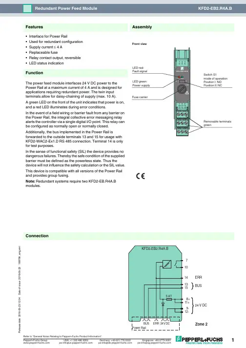
16-05-23 12:04D a t e o f i s s u e 2016-05-23189784_e n g .x m l14131571024 V DC9-12-8+11+BUSERR ConnectionAssembly•Interface for Power Rail•Used for redundant configuration •Supply current ≤ 4 A •Replaceable fuse•Relay contact output, reversible •LED status indicationFunctionThe power feed module interfaces 24V DC power to the Power Rail at a maximum current of 4A and is designed for applications requiring redundant power. The twin input terminals allow for daisy-chaining of supply (max. 10A).A green LED on the front of the unit indicates that power is on, and a red LED illuminates during error conditions.In the event of a field wiring or barrier fault from any barrier on the Power Rail, the integral collective error messaging relay alerts the controller via a single digital I/O point. This relay can be configured as normally open or normally closed.Additionally, the bus implemented in the Power Rail isforwarded to the outside terminals 13 and 15 for usage with KFD2-WAC2-Ex1.D RS 485 connection. Terminal 14 is only for test purposes.In the sense of functional safety (SIL) the device provides no dangerous failures. Thereby the safe condition of the supplied barrier must be defined as the powerless state. Thus the device will not influence the safety calculation or the SIL value.This device is compatible with all versions of the Power Rail and provides group fusing.Note: Redundant systems require two KFD2-EB.R4A.B modules.FeaturesFront view16-05-23 12:04D a t e o f i s s u e 2016-05-23189784_e n g .x mlSupplyConnection terminals 11+, 12-terminals 8+, 9-Rated voltage U n20 ... 30 V DCThe maximum rated operating voltage of the devices plugged onto the Power Rail must not be exceeded.Power dissipation ≤ 2.4 WOutputSupply Output current: ≤ 4 A Fault signal relay output: NO contactContact loading30 V AC/ 2 A / cos φ ≥ 0.7 ; 40 V DC/ 2 A Energized/De-energized delay approx. 20 ms / approx. 20 msFuse rating5 Arecommended maximum utilization of the fuse: 80 %Directive conformity Electromagnetic compatibilityDirective 2014/30/EU EN 61326-1:2013 (industrial locations)ConformityElectromagnetic compatibility NE 21:2006Degree of protection IEC 60529:2001Ambient conditions Ambient temperature -20 ... 60 °C (-4 ... 140 °F)Mechanical specifications Degree of protection IP20Mass approx. 100 gDimensions 20 x 119 x 115 mm (0.8 x 4.7 x 4.5 in) , housing type B2Mountingon 35 mm DIN mounting rail acc. to EN 60715:2001Data for application in connection with Ex-areasStatement of conformityTÜV 00 ATEX 1618 X Group, category, type of protection, temperature class ¬ II 3G Ex nA nC IIC T4Directive conformityDirective 2014/34/EU EN 60079-0:2012+A11:2013 , EN 60079-15:2010International approvals FM approval Control drawing 116-0160Approved for Class I, Division 2, Groups A, B, C, D; Class I, Zone 2, IIC UL approvalApproved for Class I, Division 2, Groups A, B, C, D; Class I, Zone 2, IIC CSA approval Control drawing 116-0160Approved for Class I, Division 2, Groups A, B, C, D; Class I, Zone 2, IIC IECEx approval IECEx UL 16.0051Approved for Ex nA nC IIC T4 Gc General information Supplementary informationStatement of Conformity, Declaration of Conformity, Attestation of Conformity and instructions have to be observed where applicable. For information see .16-05-23 12:04D a t e o f i s s u e 2016-05-23189784_e n g .x mlPower feed module KFD2-EB2The power feed module is used to supply the devices with 24 V DC via the Power Rail. The fuse-protected power feed module can supply up to 150individual devices depending on the power consumption of the devices. Collective error messages received from the Power Rail activate a galvanically-isolated mechanical contact.Power Rail UPR-03The Power Rail UPR-03 is a complete unit consisting of the electrical insert and an aluminium profile rail 35mm x 15mm. To make electrical contact, the devices are simply engaged.Profile Rail K-DUCT with Power RailThe profile rail K-DUCT is an aluminum profile rail with Power Rail insert and two integral cable ducts for system and field cables. Due to this assembly no additional cable guides are necessary.Power Rail and Profile Rail must not be fed via the device terminals of the individual devices!Accessories。
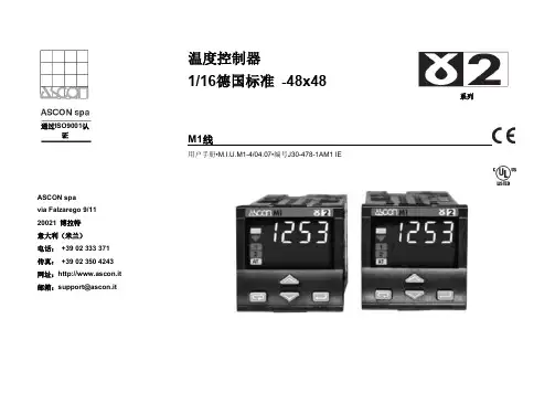
ASCON spa via Falzarego 9/11 20021 博拉特 意大利(米兰) 电话: +39 02 333 371 传真: +39 02 350 4243 网址:http://www.ascon.it 邮箱:support@ascon.it温度控制器1/16德国标准 -48x48系列M1线用户手册•M.I.U.M1-4/04.07•编号J30-478-1AM1 IE通过ISO9001认证温度控制器1/16德国标准-48x48M1线对电气安全和电磁兼容的注释在安装控制器前,请先认真阅读下列指导。
第二类仪器,后面板安装。
控制器按照以下内容设计:电气设备规则根据欧洲共同体第93/68/EEC号指令修正的欧洲共同体第73/23/EEC号指令(设备、系统和安装)以及电气设备EN61010-1 :93 + A2:95中关于强制保护要求的规则。
电磁兼容规则根据欧洲共同体第n°92/31/EEC、93/68/EEC和98/13/EEC号指令修正的欧洲共同体第n089/336/EEC号指令,并遵守以下规则:射频排放规则:EN61000-6-3 : 2001 居住环境EN61000-6-4 : 2001 工业环境射频抗扰度规则:EN61000-6-2 : 2001 工业设备和系统让安装者了解其应遵守安全要求和EMC规则至关重要。
该设备不具备可供用户使用的部件,且需要使用专用设备并通过专业工程师来操作。
因此,用户不能轻易直接对设备进行维修。
为此,生产商可为客户提供技术援助和维修服务。
欲知详情,敬请联系最近的代理商。
所有关于安全和电磁兼容信息和警告都在注释侧面标明了标志。
目录1 安装 ..................................................................................................................... 第4页 2 电气连接 ............................................................................................................. 第8页 3 产品编码 ............................................................................................................. 第14页 4 操作 ..................................................................................................................... 第18页 5 自动调准 ............................................................................................................. 第28页 6 技术规范 . (29)(可选)指示专用主要通用输入单一动作资源 工作模式 单一动作 控制警告重新传输设置点 特殊功能通过自动选择模糊调整单次对焦自动调整单次对焦固有频率RS485通讯接口参数化监督1 安装只有合格人员才能进行安装在安装控制器前,请遵守该手册中的指令,特别是标有标志的安装防范,该标志与欧洲共同体关于电气保护和电磁兼容的指令有关。
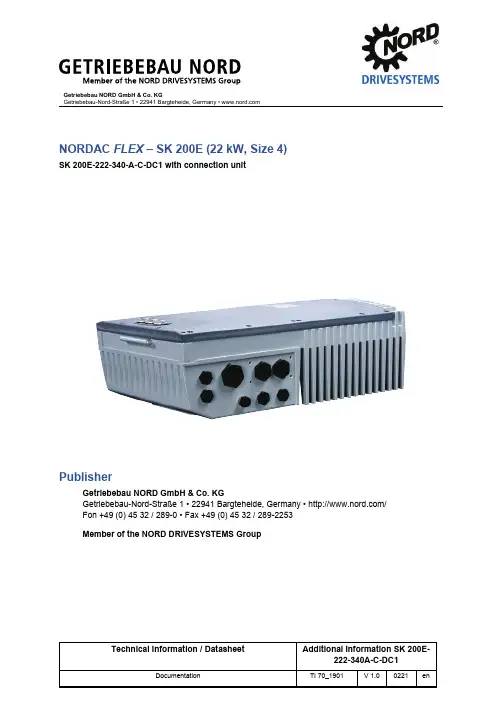
Getriebebau NORD GmbH & Co. KGGetriebebau-Nord-Straße 1 • 22941 Bargteheide, Germany • NORDAC FLEX – SK 200E (22 kW, Size 4)SK 200E-222-340-A-C-DC1 with connection unitPublisherGetriebebau NORD GmbH & Co. KGGetriebebau-Nord-Straße 1 • 22941 Bargteheide, Germany • / Fon +49 (0) 45 32 / 289-0 • Fax +49 (0) 45 32 / 289-2253Member of the NORD DRIVESYSTEMS GroupDocumentation – Additional Information SK 200E-222-340A-C-DC1 2 / 7TI 70_1901 - 0221Validity of documentThe following information applies for the following types of NORDAC FLEX series frequency inverters. • Frequency inverterSK 200E-222-340-A-C-DC1 (part number: 275137817)• Connection unitSK TI4-4-2xx-4-C-DC1 (part number: 275279914)Destruction of the frequency inverter through use of an incorrect connection unitIf the frequency inverter is not operated with the corresponding connection unit, this will result in overload of electrical components and thus to the destruction of the device.• Only operate the frequency inverter with the corresponding connection unit.The devices differ from standard devices basically in the permissible supply voltage and the connection terminals to be used for this purpose. The devices are based on the standard firmware of the NORDAC PRO SK 200E series.• The frequency inverter is to be used exclusively with the corresponding connection unit.• The connection unit is to be used exclusively with the corresponding frequency inverter.The following documents are therefore the basis for the device:1. BU 0200, edition 4920 (Part no.: 6072001)Safety information, hardware description, installation notes and software description for the basic device2. BU 0210, edition 1620 (Part no.: 6072101)Description of the POSICON function3. BU 0550, edition 1919 (Part no.: 6075501)for the description of PLC functionality4. and the following information identifying the differences of the device in comparison with BU 0200with regard to the hardware description and installation information.Documentation – Additional Information SK 200E-222-340A-C-DC1TI 70_1901 - 02213 / 71 GeneralThe following deviations from the manual apply.Chapter 1.6 Standards and approvalsThere is no approval according to UL, CSA, RCM or EAC as well as CE EX or EAC Ex !2 Assembly and installationThe following deviations from the manual apply.Chapter 2.3 Braking resistor (BR) Chapter removed.No braking resistor can be connected.Chapter 2.4.2 Electrical connection of the power unit Paragraph3. Mains cable connection: to terminals L1-L2/N-L3 and PE (depending on the device)is replaced by3. Mains cable connection: to terminals DC+ / DC- and PEDocumentation – Additional Information SK 200E-222-340A-C-DC14 / 7TI 70_1901 - 0221Chapter 2.4.2.1 Mains connection (L1, L2(/N), L3, PE) This chapter is replaced byChapter 2.4.2.1 Mains connection (DC+, DC-, PE)WARNINGElectric shockDangerous voltages can be present at the mains input and the motor connection terminals, even when the device is not in operation.• Before starting work, check that all relevant components (voltage source, connection cables, connection terminals of the device) are free of voltage using suitable measuring equipment. • Use insulated tools (e.g. screwdrivers). • DEVICES MUST BE EARTHED.Supply voltage connectionIncorrect DC supply connection results in destruction of the frequency inverter. • Observe correct polarityFuse protection must be provided by a suitable DC fuse (see technical data). For connection to or isolation from the mains, components (main switch or contactor) with suitable DC rating must be used. Isolation from or connection to the mains must always be carried out for all poles.InformationInput chokeFor improved EMC characteristics and in order to minimise the back-flowing current, an input choke can be incorporated into the mains supply cables. • Inductance: 0.3 to 0.5 mH • Nominal current: ≥ 50 AJumper positionThe jumpers for the line filters (2) must be set according to the figure (only jumpers on the right are set).CY = ONDocumentation – Additional Information SK 200E-222-340A-C-DC1TI 70_1901 - 02215 / 7Connection schemeChapter 2.4.2.3 Brake resistor (+B, -B) Chapter removed.3 Display, operation and optionsNo deviations4 CommissioningNo deviations5 ParametersNo deviations6 Operating status messagesNo deviationsDocumentation – Additional Information SK 200E-222-340A-C-DC1 6 / 7TI 70_1901 - 02217 Technical DataThe following deviations from the manual apply.Chapter 7.1 General dataFunction SpecificationPulse frequency 3.0 … 16.0 kHz, factory setting = 6 kHzPower reduction > 6 kHzAmbient conditions 3K4 IP66Hardware status EAAFirmware status V2.2 R0All other specifications remain unchanged.Chapter 7.2.2 Electrical data 400 V2) FLA – Full Load Current, maximum current for the entire mains voltage range as stated above3) FLA (S1-40°C)4) Fan cooling, temperature controlled ON= 55°C, OFF= 50°C,Run-on time if the 50°C limit is undershot and with the removal of the enable: 2 minutesDocumentation – Additional Information SK 200E-222-340A-C-DC1TI 70_1901 - 02217 / 78 Additional informationThe following deviations from the manual apply.Chapter 8.3.3 EMC of the deviceFigure 33, The wiring recommendation is to be applied analogously. • Mains connection: Instead of L1, L2/N, L3, now use DC+, DC- according to the labelling on the terminal strip • Braking resistor n/aChapter 8.4.4 Reduced output current due to low voltage Chapter removed.Chapter 8.5 Operation on the RCD Chapter removed.9 Maintenance and service informationNo deviations。
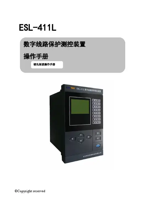
ESL-411L©Copyright reserved目录1装置简介 (1)2技术指标 (1)2.1额定工作电源 (1)2.2额定交流数据 (1)2.3交流回路过载能力 (2)2.4功率消耗 (2)2.5出口触点 (2)2.6主要技术数据 (2)2.6.1过流一段、过流二段、过流三段保护 (2)2.6.2重合闸功能 (3)2.6.3后加速功能 (3)2.6.4低周减载功能 (4)2.6.5小电流接地选线及零序过流保护 (4)2.6.6过负荷保护 (5)2.6.7失压保护 (5)2.6.8遥测精度 (5)2.6.9遥信分辨率 (5)2.7绝缘性能 (6)2.7.1绝缘电阻 (6)2.7.2介质强度 (6)2.8冲击电压 (6)2.9抗干扰能力 (6)2.10机械性能 (6)2.11环境条件 (6)3装置结构 (7)4装置硬件 (7)4.1装置命名规则 (7)4.2装置重量 (7)4.3硬件说明 (7)4.3.1CPU主板 (7)4.3.2出口板 (8)4.3.3工作电源 (8)4.3.4人机对话板(MMI板)使用说明 (8)5保护原理 (12)5.1保护启动 (12)5.2低压闭锁方向过流保护功能 (12)5.3零序过流保护功能 (13)5.4PT断线监视及母线绝缘监察功能 (13)5.5小电流接地选线功能 (14)5.6过负荷保护 (14)5.7周减载功能 (15)5.8重合闸功能 (15)5.9失压保护功能 (16)5.10控制回路断线 (16)5.11遥测功能 (17)5.12遥信采集 (17)5.13遥控 (17)6安装调试 (17)6.1通电前检查 (17)6.2装置通电检查 (17)6.2.1装置带电检查 (18)6.2.2LCD显示检查 (18)6.2.3装置遥信输入回路检查 (18)6.2.4电流电压刻度值检查 (18)6.2.5通道系数检查 (18)6.3传动试验 (18)6.3.1手动合闸检查 (18)6.3.2手动跳闸检查 (18)6.4绝缘性能检查 (18)6.5定值输入 (18)7运行维护 (18)7.1装置投运前检查 (18)7.2保护动作信号 (19)7.3LCD显示 (19)7.4运行与维护 (19)8贮存保修 (19)8.1产品包装 (19)8.2运输条件 (19)8.3贮存条件 (19)8.4保修时间 (19)9供应成套性 (20)9.1随产品供应的文件 (20)9.2随产品供应的配套件 (20)10订货须知 (20)11附录 (20)附录1:ESL-411L状态字说明 (20)附录2:ESL-411L控制字说明 (22)附录3:ESL-411L软压板清单 (23)附录4:ESL-411L定值清单 (23)附录5:ESL-411L配置清单 (24)附录6:ESL-411L遥控说明 (26)附录7:ESL-411L通道系数定义 (26)附录8:ESL-411L遥信说明 (27)12附图 (28)附图1:ESL-411L模拟量输入原理图 (28)附图2:ESL-411L出口板原理图 (29)附图3:ESL-411L端子定义 (31)1装置简介ESL-411L数字线路保护测控装置是由北京易艾斯德科技有限公司自主研发生产的新一代数字保护测控装置,产品采用国际先进的DSP和表面贴装技术,工艺成熟可靠,适用于66kV及以下电压等级,是线路单元的间隔层设备。
Sinteso™ 产品目录1. 火灾报警控制器 (1)FS1120 CI1142/S/H47 智能感知型系统控制器 (1)FS1120 CC114x-CT/S/H67 智能感知型系统控制器 (2)FS1120 CI1142/S/Rack 智能感知型系统控制器(上柜式) (3)FS1120 CC114x-/S/Rack 智能感知型系统控制器(上柜式) (4)S11/EU消防辅助设备扩充机柜(上柜式) (5)2. Sinteso智能感知型探测设备 (6)FDO221-CN 光电感烟探测器 (6)FDT241-CN 感温探测器 (7)FDOOT241-CN 烟温复合型探测器 (8)FDB221 探测器底座 (9)FDB222 探测器底座(薄型) (9)FDSB291-CN 蜂鸣器底座 (10)FDM229-CN 手动报警按钮(碎玻式) (11)FDM228-CN 手动报警按钮(可复位式) (12)FDHM228-CN 消火栓报警按钮(可复位式) (13)FDCI225-CN 输入模块(4路) (13)FDCO224-CN 输出模块(4路) (14)FDCIO223-CN 输入输出模块(2路) (15)FDCL221-CN 线路隔离模块 (16)3. 通用产品 (17)OP520光电感烟探测器 (17)HI520电子感温探测器 (17)SO520非编址探测器底座 (17)DO1101A-Ex 集合型光电感烟探测器(防爆型) (18)DT1101A-Ex 集合型电子感温探测器(防爆型) (18)DB1101A 集合型探测器底座 (18)FDL241-9-CN 线型光束感烟探测器 (19)FDLB291 线型光束感烟探测器底座 (19)DLR1191 三棱反射镜 (20)DLR1192 反射板 (20)DLR1193 反射板 (20)DLH1191A 三棱反射镜加热元件 (20)FDF241-9 红外火焰探测器 (21)FDFB291底座 (22)DF119X防雨罩 (22)MV1 红外火焰探测器安装支架 (22)MWV1 红外火焰探测器球窝铰链 (22)SB3 防爆隔离栅 (23)EOL22(EX)非编址回路终端电阻(防爆型) (23)4. 控制器功能扩展部件 (25)E3M140 FDnet回路卡 (25)E3M080 非编址回路卡 (25)E3L020 输入输出联动卡(16路) (25)E3I040 层显转换卡(LON总线) (26)E3I020 RS232通讯卡 (26)K3I050显示驱动卡 (26)E3G070 通用控制卡 (27)E3G080灭火控制卡 (27)E3H020 网络通讯卡 (28)E3X102 主CPU卡 (28)E3X103 主CPU卡 (28)B3Q565 操作显示终端 (29)TPS11R 打印机(用于上柜式控制器) (29)TPS11W 打印机(用于壁挂式控制器) (29)FC9342 联动控制盘 (30)5. 辅助设备 (31)HY2114 警铃 (31)HSG1010 声光报警器 (31)BN3002C 吸顶式音箱 (32)ZA2725A 壁挂式音箱 (32)HGM2100-24 应急广播控制器 (33)HGM2425 广播功率放大器(250W) (34)HD210 火警电话分机 (35)HD220 手提火警电话 (36)HD230 电话插孔 (36)HDM2100-24 多线式火警通讯盘24路 (37)HY5711B 总线式火警通讯盘 (38)HY5714B总线式火警电话插孔 (39)HY5716B总线式火警电话分机 (39)BCH1936 立柜(带玻璃门) (40)BCH1950 双琴台 (40)BCB8005壁挂电源8A (41)BCB8002上柜电源20A (41)BCB8003上柜电源30A (42)ZA1952/15浮冲备用电池 (42)ZA1952/24浮冲备用电池 (42)ZA1952/38浮冲备用电池 (42)NP24-12 24AH/12V 电池 (42)NP38-12 38AH/12V 电池 (42)附件1 Sinteso智能感知型火灾自动报警及联动控制系统设计参考 (43)附件2 火灾报警系统的安装指南 (52)型号功能描述/技术参数部件号设备外观1. 火灾报警控制器FS1120CI1142/S/H47100720588FS1120 CC114x-CT/S/H67100720589FS1120CI1142/S/Rack100720590FS1120 CC114x-/S/Rack100720591S11/EUBCH1950或BCH1936 100673990型号功能描述/技术参数 部件号 设备外观FDO221-CN-10... +60 -30... +75 2. Sinteso 智能感知型探测设备100718388型号功能描述/技术参数部件号设备外观FDT241-CN100718389200+50-25...-25...+70-30...+75FDOOT241-CN100718390280+70-25...-30...+751...20FDB221 FDB222FDB221 探测器底座(瑞士生产)●可编址探测器底座,明装或暗装形式均适用。
目录1. 一般调试说明 (21.1 输入输出口定义和说明:如表3-3和3-4所示.......................2 1.2 打开变频器开关...................................................3 1.3 输入密码 (3)1.4 初始化(可选项...................................................4 1.5 定位(可选项.....................................................5 1.6 判定电机旋转方向(可选项.........................................5 1.7 自学习...........................................................6 1.8 门机演示运行.....................................................7 1.9 门机正常状态设置.................................................9 1.10 力矩保护的设定.................................................11 1.11 门机与控制柜连接设置...........................................122. 高级调试步骤 (142.1 准备............................................................14 2.2 设置电机参数....................................................14 2.3 设置电机定位角..................................................14 2.4 设置电机旋转方向................................................15 2.5 设置门刀类型. (16)2.6 自学习..........................................................16 2.7 门机演示运行....................................................16 2.8 门机正常状态设置................................................16 2.9 开关门曲线......................................................173. 参数列表. (183.1 监视参数组......................................................18 3.2 现场调整参数(Field AdjustEEPROM..............................19 3.3 调节器参数Regulator ............................................20 3.4 马达参数MotorParameter ........................................20 3.5 驱动器参数Drive ScalingParameters .............................21 3.6 增强参数EnhancedParameters ....................................21 3.7 VF 参数.........................................................23 4. 常见故障的处理方法 (234.1 自学习故障......................................................23 4.2 门机不开门......................................................24 4.3 控制系统接收不到到达信号........................................24 4.4 门运行到开门限位处无停止........................................24 4.5 开门或关门时撞门 (24)4.6 开始开门或开始关门时速度过快....................................24 4.7 开关门过程中门机有抖动..........................................25 4.8 电机堵转.. (25)4.9 关门不到位时开门................................................25 4.10 门刀噪声.......................................................25 4.11 查看故障. (25w u g a o r1. 一般调试说明在门机调试之前务必保证以下事项:z电梯控制柜里门机类型设为13z根据系统地址表设置门机的相应地址z门刀底板上有防扒刀片螺栓,防扒刀片被提起z电梯处在检修状态z轿顶急停按钮被按下z轿顶与变频器之间电缆正确连接z门机安装完毕,且接线正确,未上电之前,手推拉门,门运行有阻力,拔下电机三相动力插头P4,门运行顺畅。
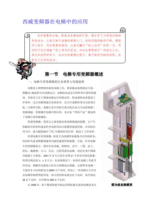
西威变频器在电梯中的应用图为垂直梯模型行研发了堪称“绿色电梯”的OH5000系列无齿轮电梯,该型号电梯采用了最先进的稀土永磁同步电机(曳引机)核心技术,配合意大利SIEI(西威:GEFRAN集团专门研发和生产运动控制变频器的子公司)的AVy系列矢量交流同/异步变频器,使西子奥的斯电梯成为中国国内无齿轮化潮流的代表产品。
与传统的齿轮电梯相比,OH5000系列无齿轮电梯在满负荷运转时最多可节能40%,平均节能则超过25%以上,相当于一年的电梯只用了三个季度的用电,将“绿色、环保”的概念演绎得淋漓尽致。
同时,OH5000系列无齿轮电梯也大大减少了磨损、热能、机械能等各类损耗,被专家鉴定为“国际先进新产品”,还被奥的斯全球总部认定为“性价比全球第一”。
2004年西子奥的斯OH5000无齿轮电梯进入市场后,引起了非常大的反响,不但引起了各房产商和建筑商的认可还得到了各地政府的大力支持。
这一举措,使电梯的核心组件——SIEI(西威)-AVy系列矢量交流同/异步变频器成为电梯行业一颗璀璨的启明星。
随着国家大力提倡节能措施,着重推荐同步变频技术和同步电梯的使用,SIEI——一个响策电梯行业的品牌随即推出了AVS、AVGL系列无机房矢量交流同步变频器,AVO、ACAC系列能量回馈型矢量交流同步变频器,AVRy系列能源再生型矢量交流同步变频器,AVRUy系列分体式大功率型矢量交流同步变频器,以及AVDL系列能源再生一体型矢量交流同步变频器。
西威现有的电梯专用变频器系列A VGL无机房变频器A VS无机房变频器A VRy能源再生变频器A Vy电梯通用型变频器变频器功能有提升空间和更新趋势变频器功能有提升空间和更新趋势变频器功能有提升空间和更新趋势该款变频器暂无功能更新等信息※ 本章节内容以AVy 系列矢量交流变频器为例,详细介绍电梯专用变频器的实际应用。
二、AVy 系列矢量交流变频器的特点与功能1、硬件构造与调试软件的特点相同的硬件结构,不同的软件设计;以及便捷的调试软件。
能源控制器Ⅰ型使用说明书青岛东软载波科技股份有限公司能源控制器类型标识代码分类说明NC X X X X-XXXX 能源控制器场景远程通信本地通信总线通信产品代号NC-能源控制器1-公变2-专变1-4G2-5G0-无1-HPLC2-微功率无线3-双模1-RS-4852-M-bus3-CAN由不大于8位的英文字母和数字组成。
英文字母可由生产企业名称拼音简称表示,数字代表产品设计序号能源控制器的功能模块类型标识代码分类见下表。
功能模块类型标识代码分类说明G X X X X-XXXX功能模块功能模块类型功能模块类型属性接口数量温度级别产品代号G-功能模块K-控制模块X-遥信模块B-本地通信模块Y-远程通信模块M-模拟量采集模块T-其他功能模块类型无补充属性,则为X;本地通信模块:Z-窄带电力线载波H-HPLCJ-微功率无线S-双模通信模块(载波&无线)M-MBUS通信模块R-RS485通信模块C-CAN通信模块T-其它信道远程通信模块:2-无线公网2G3-无线公网3G4-无线公网4G5-无线公网5GA-230MHz专网L-以太网有线网络N-公共交换电话网F-光纤有线网络T-其他信道多功能组合模块类型属性定义为:Z。
对外物理接口数量:1~9-1~9路物理接口1-C12-C23-C34-Cx由不大于8位的英文字母和数字组成,必须包含版本信息。
英文字母可由生产企业名称拼音简称表示,数字代表产品设计序号尊敬的用户:首先衷心感谢您选择青岛东软载波科技股份有限公司的产品。
青岛东软载波科技股份有限公司成立于1993年6月,2011年2月在创业板上市,现已形成以智能制造为基础,芯片设计为源头,能源互联网与智能化应用两翼齐飞的产业布局。
公司发展战略是以集成电路设计为基础,开展以融合通信为平台的技术研发;布局“芯片、软件(模组)、终端、系统、信息服务”产业链,聚焦能源互联网、智能化应用这两个战略新兴领域,打造国际一流企业。
VFGL旋转开关功能对照表MON1与MON0之故障及功能对照表MON1 →0MON0 →0 →状态表示→E0 没有异常→E1 速度异常过低时检出(SW_TGBL)→E2 速度过大时检出(SW_TGBH)→E3 逆转时检出(SW_TGBR)→E4 AST异常时检出(SW_AST)→E5 逆变器过电流时检出(SS_IOCFO)→E6 整流器过电压时检出(SS_COVH)→E7 整流器电压不足时检出(SS_LVLT)→E8 #LB线圈故障断电时检出(SS_CFLB)→E9 #5线圈故障断点检出(SW_CF5)→EA 抱闸接点ON/OFF故障时检出(SW_CFBK)→EB 机厢直接传输信号异常(ST_STSCE)→EC 厅站直接传输信号异常(ST_STSHE)→ED 系统异常(ST_SYER)→EE 驱动不能再启动(SD_DNRS)→EF 控制不能再启动(SW_NRS)VFGL旋转开关功能对照表故障检查记录时,MON1与MON0之对照表MON1 →1 或5 *1MON0 →0 →控制S/W NRS →E00 没有异常不能再启动原因→E01 温度异常(SW_THMFT)→E02 紧急停止运行纪录1次(SW_EST1)→E03 CC-WDT3次检出(SS_CCWC3)→E04 SLC-WDT3次检出(SS_SLCWC3)→E05 过电流检出(SW_SOCR)→E06 回生电阻负荷大(SW_SOLR)→E07 41DG闸锁线路异常(SW_E41)→E08 终端限位异常(SW_TSCK)→E09 PAD异常检出(SW_PAD)→E0A 称数值异常检出(SW_WGER)→E0B E1板异常(SW_E1FBC)→E0C UHS/DHS开关异常(SW_UDHSE)→E0D DZ检查回路异常(SW_DZCER)→E0E #5接触器短接故障(SW_5ONER)→E0F #LB 接触器短接故障(SW_LBONER)→1 →状态表示→E10 没有异常→E11 复位后重试不能(SW_RSRTC)→E12 士力铊16次异常检出(ST_SELD)→E13 直接传输CPU传送异常(ST_STER)→E14 电容器异常检出(ST_CAPC)→E15 手动按钮异常(ST_HDOK)→E16 模式与测试数据偏差异常(SD_OVJP)→E17 #LB线圈连续5次异常断电检出(ST_DFLB)→E18 #5线圈连续5次异常断电检出(ST_DF5)→E19 抱闸接点回路连续5次异常检出(ST_DFBK1)→E1A抱闸接点2回路连续5次异常检出(ST_DFBK2)→E1B整流器电压不足5次检出(ST_DFLV)→E1C E1-1板失效(ST_ARME1)→E1D 逆变器风扇故障(ST_ARME2)→E1E E1-2板失效(ST_ARME3)→E1F 逆变器风扇或E1板故障(ST_ARME4)→2 →状态表示→E20 无异常→E21 #5接触器短接故障(SW_E5)→E22 紧急停止运行纪录2次(SW_EST2)→E23 系统异常(ST_SYER)→E24 回复后再尝试检出(ST_RSRQH)→E25 集机驱动板异常(SS_GDFH)→E26 DT_CT异常(SD_CTER)→E27 #RL回路短路故障(SW_RLONER)→E28 湿度感应器异常(SC_FSWERR)→E29 完成防潮湿操作(SC_FSWFDM)→E2A #PWD连续3分钟断开指令(SW_PWDFT)→E2B 折叠式围栏开关(SW_HRSOKI)→E2C 制动器拖曳结束(ST_BKSNG)→E2D 制动器重试故障(SW_RFBK2)→E2E士力铊错误运行16次检出(ST_SELE)→E2F #BK回路短路故障(SW_AKER)*1 MON1=1 :没有锁存记忆;MON1=5 :附有锁存记忆VFGL旋转开关功能对照表故障检查记录时,MON1与MON0之对照表MON1 →1 或5 *1MON0 →3 →控制S/W ESTOP→E30 没有异常不能再启动原因→E31 MELD之负荷过大(SD_SLIT)→E32 异常低速(SW_TGBL)→E33 速度异常过高(SW_TGBH)→E34 AST异常动作(SW_AST)→E35 逆转运行(SW_TGBR)→E36 AST异常动作(SW_ASTW)低速机使用→E37 AST异常动作(SW_ASTWV)低速机使用→E38 逆变器电压过高检出(SS_COVH)→E39 逆变器电压过低检出(SS_LVLT)→E3A CC-WDT4次异常检出(SS_CCWC4)→E3B SLC-WDT4 次异常检出(SS_SLCWC4)→E3C 逆变器电流过大时检出(SS_IOCFO)→E3D SLC-CPU内之紧急停止动作检出(SS_DEST)→E3E 编码器故障(自动)(SW_TACH1)→E3F 编码器故障(手动)(SW_TACH2)→ 4 →状态表示→E40 没有异常→E41 紧急停止运行纪录2次(SW_EST2)→E42 逆变器电压过低时检处(SS_LVLTT)→E43 紧急停止回复(SW_ESTR)→E44 #LB线圈故障断电时检出(SW_CFLB)→E45 #5线圈故障断电时检出(SW_CF5)→E46 抱闸线圈1异常时检出(SW_CFBK1)→E47 抱闸线圈2异常时检出(SW_CFBK2)→E48 电源接合(SY_89ST)→E49 125V电源低电压检出(SW_79ERLT)→E4B 逆变器整流回路异常(SW_CVER)→ 5 →状态表示→E50 无异常→E51 #29安全回路检出(SN_29)→E52 #29安全回路动作时检出锁存记忆(SS_29LT)→E53 欠相或电压过低时检出(SS_PWFH)→E54 逆变器电压不足时检出(SS_LVLT)→E55 12V电源异常(SS_12VFL)→E56 控制板门打开(SN_PCH)→E57 手动模式时电流负荷过大(SD_HRT)→E58 驱动发出之紧急停止指令(SD_32GQ)→E59 紧急停止指令(SC_S29)→E5A 125V电源低电压检出(SN_79ER)→E5B 制动器滑行距离异常(ST_SLIPER)*1 MON1=1 :没有锁存记忆;MON1=5 :附有锁存记忆故障检查记录时,MON1与MON0之对照表MON1 →1 或5 *1MON0 →6 →H/W安全回路→E60 没有异常异常原因→E61 逆变器电压不足时检出(SW_32DT10)→E62 集极驱动基板异常(SW_32DT16)→E63 逆变器保护回路动作(SW_DSTR10)→E64 #29安全回路动作时检出(SS_29LT)锁存记忆→E65 12V电源异常→E66 散热器温度超过75 o C时检出(ST_THMF1)→E67 散热器温度超过90 o C时检出(ST_THMF2)→E68 散热器遇冷/脱离插座(ST_THMF3)→E69 逆变器电流过大时检出(SS_IOCFO)→E6A 逆变器电压过大时检出(SS_COVH)→E6B 欠相或电源过低时检出(SS_PWFH)→E6C E1板报警(SS_EALH)→E6D 直流电源异常(SS_PSPFH)→E6E 交流电源异常(SS_AC)→E6F 电源异常检出(SS_RPU)→7 → H/W 安全回路→E70没有异常异常原因→E71 CC-WDT5次异常检出(SS_CCWC5)→E72 CC-WDT4次异常检出(SS_CCWC4)→E73 CC-WDT3次异常检出(SS_CCWC3)→E74 SLC-WDT5次异常检出(SS_SLCWC5)→E75 SLC-WDT4次异常检出(SS_SLCWC4)→E76 SLC-WDT3次异常检出(SS_SLCWC3)→8 →制动器回路→E80没有异常异常原因→E81 #BK回路过电流(SW_SBKOC)→E83 #BK1的DC-CT未连接(SW_BKNC1)→E84 #BK2的DC-CT未连接(SW_BKNC2)→E85 #BK1线圈失效(SW_SBKBD1)→E86 #BK2线圈失效(SW_SBKBD2)→E89 #BK1的DC-CT失效(SW_SBKCE1)→E8A #BK2的DC-CT失效(SW_SBKCE2)→E8B #BK1线圈短路(SW_SBKAS1)→E8C #BK2线圈短路(SW_SBKAS2)→9 →驱动S/W异常→E90没有异常原因→E91 驱动软件异常急停→E92 电流负荷过大(SD_OCR)→E93 不能再次起动(SD_DNRS)→E94 MELD负荷过大检出(SD_SLIT)→E95 TSD开关异常(SD_TSDP)→E96 秤异常检出(SD_WGHTF2)→E97 DC-CT异常检出(SD_CTER)→E98 TSD运行动作检出(SD_TSA)→E99 摩达解码器之”Z”相异常检出(SD_AZER)→E9A摩达解码器之”F”相异常检出(SD_AEER)→E9B PM摩达时限电流过大(SD_TOCR)→E9E 闸极切断线路异常(SD_CEVV)*1 MON1=1 :没有锁存记忆;MON1=5 :附有锁存记忆故障检查记录时,MON1与MON0之对照表MON1 →1 或5 *1MON0 →A →驱动S/W 异常→EA0 没有异常原因→EA1模式与测速数据偏差异常(SD_PVJP)→EA2模式与测速数据偏差异常(SD_OVJP)→EA3驱动发出之紧急停止指令(SD_32GQ)→EA4 回生电阻负荷过大(SD_OLR)→EA6 手动模式运行时限(SD _HRT)→EA7 逆变器电流过大时检出(SD _IOCF)→EA8 TSD-PAD故障检出(SD _PADE)→EA9平称装置传输错误(SD _WEGR)→EAB ARL感应器短路故障(SD _RLERR)→B→管理S/W →EB0 没有异常异常原因→EB1 停机10分钟后不能再起动(SW_32DT10)→EB2 停机16分钟后不能再起动(SW_32DT16)→EB3 不能再起动超过10分钟(SW_DSTR10)→EB4 不能再起动超过10分钟(SW_57EBT)→EB5 门不能开启超过2分钟(SW_CONE)→EB6 FUSE短路超过2分钟(SW_EFSOF)→EB7 #60异常检出(SW_60CHK)→EB8 门不能开启(SW_NLH)→EB9 主控制板异常检出(SQ_MBCIJH)→EBA 两感应器ON故障(SW_MBSONK)→EBB 困人警报(SZ_EMAH)→EBC 不能使用警报(SZ_EMBH)→EBD 群控管理异常(SZ_GCIJO)→EBE 厢站电源故障(SW_PWER)→EBF 两感应器OFF故障(SW_MBSOFR)→C→SLC异常原因→EC0 没有异常→EC1 SLC传输异常(SS_TRER)→EC2 SLC之紧急停止动作(SS_DEST)→EC3 SLC内之速度过高(SS_TGBH)→EC4 SLC内之AST动作(SS_AST)→EC5 SLC内之KC动作(SS_DKC)→EC6 SLC之RAM之异常检出(SS_RAMER)→D→讯号传输异常→ED0 没有异常原因表示→ED1 机厢正门按钮BC-CPU1异常检出(SF_FBC1IJH)→ED2 机厢正门按钮BC-CPU2异常检出(SF_FBC2IJH)→ED3 机厢正门按钮BC-CPU3异常检出(SF_FBC3IJH)→ED4 机厢正门按钮BC-CPU4异常检出(SF_FBC4IJH)→ED5 正门CAR-STATION之CPU异常检出(SF_FCSIJH)→ED6 正门控制之CPU异常检出(SF_FDCIJH)→ED7 正门机厢显示灯之CPU异常检出(SF_FICIJH)→ED8 正门机厢之OPTION-CPU异常检出(SF_FCZIJH)→ED9 SC-CPU严重故障(SC_SCER8)→EDA SH-CPU严重故障(SC_SHER8)→EDB SC-CPU轻微故障(SC_SCER)→EDC SH-CPU轻微故障(SC_SHER)→EDD HS-CPU故障(SC_HSAIJ)故障检查记录时,MON1与MON0之对照表MON1 →1 或5 *1MON0→E→讯号传输异常→EE0 没有异常原因表示→EE1 机厢后门按钮BC-CPU5异常检出(SF_RBC5IJH)→EE2 机厢后门按钮BC-CPU6异常检出(SF_RBC6IJH)→EE3 机厢后门按钮BC-CPU7异常检出(SF_RBC7IJH)→EE4 机厢后门按钮BC-CPU8异常检出(SF_FBC8IJH)→EE5 后门CAR-STA TION之CPU异常检出(SF_RCSIJH)→EE6 后门控制之CPU异常检出(SF_RDCIJH)→EE7 后门机厢显示灯之CPU异常检出(SF_RICIJH)→EE8 后门机厢之OPTION-CPU异常检出(SF_RCZIJH)。
Ergonomic design and advanced functionality. The NSG 438 ESD simulator is designed to sit comfortablyin the operator’s hand, with operating conditions constantly displayed and accessible on a bright, clearcolor touch display.NSG 438 comprehensively fulfi lls virtually all international standard requirements. Based on over 60optional discharge networks, the NSG 438 can meet any of today’s automotive manufacturers’ standards.The simulator is simple, convenient and safe to use. The whole range of parameter settings includingpolarity selection, freely adjustable pulse repetition, counter functions and discharge detection is avail-able up to the maximum discharge voltage.The color touch display and keypad for parameter input shows the precise functional and test data withuser-selectable language for convenient and safe operation worldwide. The simulator contains variablethreshold selection for accurate discharge detection. This detection feature can be switched off whentesting EUT’s with non-conductive surfaces, such as plastic housings. Pre-programmed settings for IEC61000-4-2 and ISO 10605 ensure that the simulator is automatically set up correctly and the appropri-ate discharge network is installed. The actual RC value is displayed at all times. Molded HV dischargenetworks in solid cases eliminate ionization and leakage current effects. Precisely tuned combinationsof RC components guarantee wave shape parameters to be within tolerances. A unique activity log isincluded so that the types and numbers of ESD simulations can be easily scrolled through to check whathas been tested and in what timeframe.The simulator is recalibrated and adjusted at every start, or with a simple tap of the screen. This built-incalibration and self-test feature, in conformance with the ISO standard can save considerable time.For extra safety, an interlock and an emergency stop switch is built in. Additional features include freelyadjustable pulse repetition rate, a special random generator function and an optional charge removerfor discharging the EUT.Air- and contact-discharge to30 kVBattery tested to 30’000discharges at 30 kVColor touch panel controlAdvanced voltage-hold featureActivity logCompliant with a huge range ofOEM and international standardsBuilt-in ISO self-calibrationprocedureEasily and quickly interchange-able discharge networksSelectable discharge detectorOPTIMIZED FOR AUTOMOTIVE TESTINGNSG 438 FLAGSHIP ESD SIMULATORTechnical specifications © March 2014 Teseq ®Specifications subject to change without notice.Teseq ® is an ISO-registered company. Its productsare designed and manufactured under the strictquality and environmental requirements of the ISO9001. This document has been carefully checked.However, Teseq ® does not assume any liability forerrors or inaccuracies.Teseq AGNordstrasse 11F 4542 Luterbach SwitzerlandT + 41 32 681 40 40 F + 41 32 681 40 48***************691-028C March 2014OPTIMIZED FOR AUTOMOTIVE TESTING NSG 438 FLAGSHIP ESD SIMULATOR。
S S -PSS Series Compatible Mounting with a SimpleConstruction and Easy-to-Use Design Concept●One-piece terminal construction to keep out flux. ●A single leaf movable spring construction. ●Conforms to North American and European safety Standards.●1 mm MIN Contact Gap Models available for Interlock applicationsRoHS CompliantModel Number LegendList of Models●0.5 mm Contact Gap Models●1 mm MIN Contact Gap ModelsContact FormSS -@@@1. Ratings3 : 125 VAC 3 A 01 : 30 VDC 0.1 A2. ActuatorNone : Pin plunger L : Hinge leverL13 : Simulated roller lever L111 : Long hinge lever123 3. TerminalsNone : Solder terminalsT : Quick-connect terminals (#110) D : P CB terminalsG P Dummy●SPDT●SPST-NO (SS-3FP models)Separator (Sold Separately), Terminal Connector (Sold Separately)Refer to "Basic Switch Common Accessories "SS-P Subminiature Basic SwitchS S-P Contact Specifications*Please refer to "Using Micro Loads" in "●Precautions" for moreinformation on the minimum applicable load.RatingsNote 1.The above rating values apply under the following test conditions.(1) Ambient temperature: 20±2°C(2) Ambient humidity: 65±5%(3) Operating frequency: 20 operations/minNote 2.Consult your OMRON sales representative for information on modelsfor other loads.Approved Safety StandardsUL (UL1054/CSA C22.2 No.55)VDE (EN61058-1)Testing conditions: 5E4 (50,000 operations) T55 (0 to 55°C) CharacteristicsNote.The data given above are initial values.*1.The values for dielectric strength shown are for models with a Separator (refer to "Micro Switch Common Accessories").*2.The values are at Free Position and Total Travel Position values for pin plunger, and Total Travel Position value for lever.Close or open circuit of the contact is 1 ms max.*3.For testing conditions, consult your OMRON sales representative.Item Model SS-3P models SS-01P models SS-3FP modelsContactSpecification Rivet Crossbar RivetMaterial SilverGoldalloySilverGap(standardvalue)0.5 mm 0.5 mm 1 mm min.InrushcurrentNC9 A max. -9 A max.NOMinimum applicable load(reference value) *5 VDC 160 mA 5 VDC 1 mA 5 VDC 160 mAModelSS-3P /SS-3FP modelsSS-01P modelsRated voltage Item Resistive load125 VAC 3 A 0.1 A30 VDC 3 A 0.1 AModel SS-3P / SS-3FP SS-01PRated voltage Item Resistive load125 VAC 3 A 0.1 A30 VDC 3 A 0.1 ARated voltage Model SS-3P / SS-3FP SS-01P125 VAC 3 A 0.1 A30 VDC 3 A 0.1 AItem Model SS-3P models SS-01P models SS-3FP modelsPermissible operating speed 0.1 mm to 1 m/s (for pin plunger models)PermissibleoperatingfrequencyMechanical 300operations/min Electrical 30operations/min Insulation resistance 100 MΩ min. (at 500 VDC with insulation tester)Contact resistance (initial value) 50 mΩ max. 100 mΩ max. 50 mΩ max.Dielectricstrength *1Between terminals of thesame polarity1,000 VAC 50/60 Hz for 1 minBetween current-carryingmetal parts and ground1,500 VAC 50/60 Hz for 1 minBetween each terminalsand non-current-carryingmetal parts1,500 VAC 50/60 Hz for 1 minVibrationresistance *2Malfunction 10 to 55 Hz, 1.5 mm double amplitudeShockresistanceDurability 1,000m/s2 {approx. 100G} max.Malfunction *2300 m/s2 {approx. 30G} max.Durability *3Mechanical 1,000,000 operations min. (60 operations/min)100,000 operations min.(60 operations/min)Electrical70,000 operations min.(20 operations/min, 125 VAC) 200,000 operations min.(20 operations/min)100,000 operations min.(20 operations/min, 30 VDC)100,000 operations min.(20 operations/min, 30 VDC)Degree of protection IEC IP40Degree of protection against electricshockClass IProof tracking index (PTI) 250Ambient operating temperature -25°C to +85°C (at ambient humidity of 60% max.) (with no icing or condensation)Ambient operating humidity 85% max. (for +5 to +35°C)Weight Approx. 1.6 g (pin plunger models)SS-PSubminiature Basic SwitchS S -PTerminals/Appearances (Unit: mm)Mounting Holes (Unit: mm)Dimensions (Unit: mm) and Operating CharacteristicsThe illustrations and dimensions are for models with solder terminals. Refer to "Terminals/Appearances" for details on models with quick connect terminals (#110) or PCB terminals.Note 1.Unless otherwise specified, a tolerance of ±0.4 mm applies to all dimensions. Note 2.The operating characteristics are for operation in the A direction ().●Solder terminals●Quick Connect Terminals (#110)●PCB terminals<PCB Mounting Dimensions (Reference)>2-2.4 dia. mounting holes ●Pin plunger SS-3GP SS-01GPOperating characteristics Model SS-3GP SS-01GPOperating ForceOF Max. Releasing ForceRFMin.1.50 N {153 gf}0.2 N {20 gf}Pretravel PT Max. Overtravel OT Min. Movement Differential MD Max. 0.6 mm 0.4 mm 0.15 mm Operating PositionOP8.4±0.3 mm●Hinge leverSS-3GLP SS-01GLPOperating characteristics Model SS-3GLP SS-01GLPOperating ForceOF Max.Releasing ForceRFMin.0.5 N {51 gf}0.05 N {5 gf}Overtravel OT Min. Movement Differential MD Max. 1.0 mm 0.8 mmFree PositionFP Max.Operating Position OP13.6 mm 8.8±0.8 mm●Long hinge lever SS-3FL111P-3Operating characteristicsModel SS-3FL111P-3Operating Force OF Max.Releasing Force RFMin.0.55 N {56 gf}0.01 N {1 gf}Overtravel OT Min. Movement Differential MD Max. 1.0 mm 3.0 mm Free PositionFPMax.Operating PositionOP16.8 mm 8.8±1.5 mmSS-PSubminiature Basic SwitchS S -PNote 1.Unless otherwise specified, a tolerance of ±0.4 mm applies to all dimensions. Note 2.The operating characteristics are for operation in the A direction ().Precautions★Please refer to "Common Precautions" for correct use.●Soldering•Connecting to Solder TerminalsComplete the soldering at the iron tip temperature of 350 to 400°C within 5 seconds, and do not apply any external force for 1 minute after soldering. Soldering at an excessively high temperature or soldering for more than 5 seconds may deteriorate the characteristics of the Switch. •Connecting to PCB terminalsWhen using automatic soldering baths, we recommend soldering at 260±5°C within 5 seconds. Make sure that the liquid surface of the solder does not flow over the edge of the board.When soldering terminals manually, complete the soldering at the iron tip temperature between 350 to 400°C within 3 seconds, and do not apply any external force for 1 minute after soldering. When applying solder, keep the solder away from the case of the Switch and do not allow solder or flux to flow into the case.●MountingUse M2.3 mounting screw with plane washers or spring washers to securely mount the Switch. Tighten the screws to a torque of 0.23 to 0.26 N·m {2.3 to 2.7 kgf·cm}.●Using Micro LoadsUsing a model for ordinary loads to open or close the contact of a micro load circuit may result in faulty contact. Use models that operate in the following range. However, even when using micro load models within the following operating range, if inrush current occurs when the contact is opened or closed, it may increase the contact wear and so decrease durability. Therefore, insert a contact protection circuit where necessary. The N-level reference value applies for the minimum applicable load. This value indicates the malfunction reference level for the reliability level of 60% (λ60).(JIS C5003)The equation, λ60=0.5×10⁻⁶/operation indicates that theestimated malfunction rate is less than operations with a reliability level of 60%.●Simulated roller lever SS-3GL13PSS-01GL13POperating characteristicsModel SS-3GL13P SS-01GL13P Operating Force OF Max.Releasing Force RFMin.0.5 N {51 gf}0.05 N {5 gf}Overtravel OT Min. Movement Differential MD Max. 1.0 mm 0.8 mm Free PositionFPMax.Operating PositionOP15.5 mm 10.7±0.8 mmCautionsCorrect Use12,000,000Current (mA)V o l t a g e (V )SS-PSubminiature Basic SwitchS S -P• Application examples provided in this document are for reference only. In actual applications, confirm equipment functions and safety before using the product.• Consult your OMRON representative before using the product under conditions which are not described in the manual or applying the product to nuclear control systems, railroad systems, aviation systems, vehicles, combustion systems, medical equipment, amusement machines, safety equipment, and other systems or equipment that may have a serious influence on lives and property if used improperly. Make sure that the ratings and performance characteristics of the product provide a margin of safety for the system or equipment, and be sure to provide the system or equipment with double safety mechanisms.Cat. No.B108-E1-050716(0207)(O)Note: Do not use this document to operate the Unit.OMRON CorporationElectronic and Mechanical Components CompanyContact: /ecb。
模拟开关型号大全z开关及驱动器件制造商 产品类别 产品型号 产品描述TI公司 模拟开关CD4066BM 四双边开关CD74HC123M 高速CMOS双路可再触发单稳多谐振荡器CD74HC4051E 高速CMOS模拟多路开关CD74HC4051M 高速CMOS模拟多路开关CD74HC4052M 高速CMOS模拟多路开关CD74HC4053M 高速CMOS模拟多路开关CD74HC4053PW 高速CMOS模拟多路开关CD74HC4066PW 模拟开关CD74HCT4052M96 高速CMOS模拟多路开关SN74ALS35AN 六同相器(集电极开路输出)SN74AUC1G66DBVR 单模拟开关SN74HC4066D 四路双向模拟开关SN74HC4066DBR 四路双向模拟开关SN74HC4066DR 四路双向模拟开关SN74LV4066AD 四路双向模拟开关SN74LV4066ADR 四路双向模拟开关SN74LVC1G66DBVR 单模拟开关SN74LVC1G66DCKR 单模拟开关SN74LVC1G66DCKT 单模拟开关SN74LVC2G66DCTR 双模拟开关SN74LVC2G66DCUR 双模拟开关SN74LVC2G66DCUT 双模拟开关ON公司 模拟开关MC14051BDR2 模拟开关多路器MC74VHC1G66DTT1 单模拟开关MC74VHC1GT66DTT1 单模拟开关NL7WB66US 双单刀单掷模拟开关NLAS1053US 单单刀双掷模拟开关NLAS2066US 双单刀单掷模拟开关及过压容许NLAS323US 双单刀单掷模拟开关及单电源供电 NLAS324US 双单刀单掷模拟开关 NLAS325US 双单刀单掷模拟开关 NLAS44599DT 双双刀双掷模拟开关NLAS44599DTR2 低电压,单电源,双路DPDT 模拟开关 NLAS4501DTT1 单模拟开关 NLAS4599DFT2 单单刀双掷模拟开关 NLAS4599DTT1 单模拟开关 NLAS4684FCT1 双单刀双掷模拟开关 NLAS4685FCT1 双单刀双掷模拟开关 NLASB3157DFT2 单单刀双掷模拟开关NLAST44599DT 低电压,单电源,双路DPDT 模拟开关 NLAST44599DTR2 双模拟开关 NLAST4501DTT1 单模拟开关 NLAST4599DTT1单模拟开关ADG211AKN替换DG211,宽工作温度范围 ADG333ABN 与MAX333A 兼容模拟开关 ADG431BN逻辑1=ON,与MAX326兼容 ADI 公司模拟交叉点开关DG441DY4路, TTL 输入SPST 模拟开关(NClosed) DG442DJ 4路, TTL 输入SPST 模拟开关(NOpen) DG442DY 模拟开关, SPST, Quad, NOpen, TTL 输入ISL43110IB 低压,单电源SPST 高性能模拟开关(NOpen)ISL43111IB 低压,单电源SPST 高性能模拟开关(NClosed)ISL43112IB 低压,双电源SPST 高性能模拟开关NOpenISL43113IB 低压,双电源SPST 高性能模拟开关(NClose)ISL43140IB 低压,单电源和双电源4路SPST 高性能模拟开关(NClose)ISL43143IR 低压,单电源和双电源4路SPST 高性能模拟开关(NClose)INTERSIL 公司模拟开关 ISL43144IR低压,单电源和双电源4路SPST 高性能模拟开关(NOpen)ISL43410IR 低压,单电源DPDT高性能模拟开关z视频矩阵开关制造商 产品类别 产品型号 产品描述ADI公司 矩阵开关 AD8182AN 带宽800MHz视频多路转换器z总线开关制造商 产品类别 产品型号 产品描述SN74CB3T3125PW 四总线开关TI公司 总线开关SN74CB3T3245PW 8位FET2.5-V/3.3-V 低电压总线开关SN74CBT16210CDL 20位FET开关总线-2V脉冲保护器SN74CBT16210CDLR 20位FET开关总线-2V脉冲保护器SN74CBT16210DGGR 20位FET开关总线-2V脉冲保护器SN74CBT3125D 四总线开关SN74CBT3244DBR 八总线开关SN74CBT3244DW 八总线开关SN74CBT3245ADW 八总线开关SN74CBTD16211DGVR 24位总线开关SN74CBTD16211DL 24位总线开关SN74CBTD3306D 双总线开关(带电平转换)SN74CBTD3306PW 双总线开关(带电平转换)SN74CBTD3306PWR 双总线开关(带电平转换)SN74CBTD3384DBR 10位总线开关(带电平转换)SN74CBTD3861DBR 10位总线开关(带电平转换)SN74CBTD3861PW 10位总线开关(带电平转换)SN74CBTD3861PWR 10位总线开关(带电平转换)SN74CBTLV3125D 四总线开关SN74CBTLV3245ADW 八总线开关SN74CBTS3306D 双总线开关z 固态开关 制造商 产品类别 产品型号 产品描述 ACS102-5T1 ACS102-5TA ACS108-5SA ACS108-5SN ACS110-7SB2 ACS110-7SN ACS120-7SB ACS120-7ST ACS302-5T3 ACS402-5SB4 ACST4-7SB ACST4-7SFP ACST6-7SG ACST6-7ST ST 公司固态开关ACST8-8CFPz 带保护的电子开关 制造商 产品类别 产品型号 产品描述TPS2010AD 0.4A,2.7~5.5V 单高端MOSFET 开关集成电路,低电平使能TPS2010D 0.4A,2.7~5.5V 单高端MOSFET 开关集成电路,低电平使能TI 公司电流限制开关TPS2062D1A,2.7~5.5V 单高端MOSFET 开关集成电路,低电平使能z 干簧管 制造商 产品类别 产品型号 ORD228 通用微型 干簧管 ORD9216通用微型z 模拟多路器 制造商 产品类别 产品型号 产品描述 DG408DJ DG408DY DG409DJ ISL43640IR ISL43681IR INTERSIL 公司模拟多路器ISL43741IRADI 公司 多路复用器z 带状态报告的开关 制造商 产品类别 产品型号 产品描述 MC33143DW 双高端开关 MC33286DW 双高端开关MC33288ADH 大电流白炽灯固态继电器 MC33288BDH 大电流白炽灯固态继电器 MC33288CDH 大电流白炽灯固态继电器 MC33288DH 大电流白炽灯固态继电器 MC33289DW 电感负载的双高端开关 MC33486ADH H 桥负载的双高端开关MC33982PNA 带诊断和保护的自保护2mOhm 开关 高端开关MC33984PNA双高端开关MC33291DW 带SPI 接口的1.2欧RDS(on)8输出开关MC33291LDW 带SPI 接口的1.6欧RDS(on)8输出开关MC33298DW 带SPI I/O 控制的0.8欧RDS(on)8输出开关MC33298P 带SPI I/O 控制的0.8欧RDS(on)8输出开关MC33385DH 0.25欧RDS(on)4小灌电流驱动器 MC33397DW 带SPI 和并口输入控制的0.9欧RDS(on)2或6输出开关MC33880DW 1欧RDS(on)可设置8SPI 控制开关 MC33880DWB 1欧RDS(on)可设置8SPI 控制开关 FREESCALE 公司低端开关MC33882DH带SPI 和并口输入控制的0.8欧RDS(on)6输出开关z 带监测的开关 制造商 产品类别 产品型号 产品描述 H 桥和可配置开关 H 桥步进马达MC33287DW 接触监测及双低端保护驱动器 MC33884DW开关监测接口 MC33972DWB 开关监测接口FREESCALE 公司带监测的开关MC33993DWB 22输入多开关监测接口。