新网络锁使用指南
- 格式:doc
- 大小:1010.50 KB
- 文档页数:2

无线网络已经成为现代社会的重要组成部分,人们越来越依赖于它来满足各种需求,如上网冲浪、社交娱乐、办公学习等。
然而,随之而来的问题是无线网络的安全性,因为信号可以穿墙传播,不法分子可以利用技术手段侵入我们的网络。
为了保护自己的隐私和数据安全,我们需要学会正确地使用无线网络加密技术。
本文将从入门到精通,为大家提供无线网络加密使用指南。
1. 了解无线网络加密的重要性对于无线网络的加密,很多人可能觉得无所谓,但实际上加密是保护网络安全的重要手段。
没有加密的无线网络信号,任何人都可以轻松地截取到传输中的数据,这就涉及到个人信息的泄露和网络被黑客攻击的风险。
因此,我们必须认识到无线网络加密的重要性,并采取适当的措施来保护我们的网络。
2. 入门级加密方式:WEPWEP(Wired Equivalent Privacy)是最早的无线网络加密方式,它使用固定的密码对数据进行加密。
尽管WEP在过去被广泛使用,但随着技术的发展,它的安全性已经被证明是相当脆弱的。
黑客可以很容易地通过抓包工具破解WEP密码,因此不建议使用WEP来保护我们的无线网络。
3. 中级加密方式:WPA/WPA2WPA(Wi-Fi Protected Access)和WPA2是目前常用的无线网络加密方式。
它们使用更加复杂和安全的加密算法,提供了更高的安全性。
WPA/WPA2允许我们使用自定义的密码来保护网络,密码长度至少应该大于8位,并且应该包含字母、数字和特殊字符等元素,以增加密码的复杂性。
另外,我们还可以定期更换密码,以防止黑客破解。
4. 高级加密方式:WPA3WPA3是最新发布的无线网络加密标准,它提供了比WPA/WPA2更加强大和安全的加密算法。
相比于WPA/WPA2,WPA3在密钥交换和身份验证方面有了更多的改进,减少了黑客攻击的可能性。
然而,由于WPA3还比较新,目前并没有广泛应用,而且在硬件设备上的支持也较为有限。
不过,随着技术的发展,我们相信WPA3会逐渐普及。

物联网安全使用方法:保护智能门锁免受入侵随着物联网的快速发展,智能家居得到越来越广泛的应用。
智能门锁作为其中的一种重要设备,方便了我们的生活。
然而,物联网设备也存在一定的安全风险,使用不当可能导致入侵和信息泄露。
为确保智能门锁的安全使用,我们需要采取一些措施来保护它免受入侵。
1. 更新固件和软件智能门锁通常会配备固件和软件,为了保持其安全性,应定期更新固件和软件版本。
厂家会发布修复已知漏洞或强化安全性的更新,及时安装这些更新是防范潜在攻击的关键。
可以在智能门锁对应的官方网站或APP中查找相关信息并下载更新,确保设备始终处于最新的安全状态。
2. 设置强密码强密码是防止入侵的重要手段。
智能门锁通常会有密码登录功能,设置一个强密码可以提高安全性。
不要使用简单的密码,如生日、电话号码或连续数字等,而是选择包含字母、数字和特殊符号的复杂密码。
此外,定期修改密码也是保护安全的一种方式,建议每三个月更换一次密码。
3. 启用双因素认证双因素认证是一种可以提高安全性的有效措施。
智能门锁通常支持双因素认证,通过手机短信验证码、指纹识别或面部识别等方式,在输入密码后再进行身份验证。
启用双因素认证可以防止密码被盗用或破解,在一定程度上提高了智能门锁的安全性。
4. 使用安全的Wi-Fi网络智能门锁通常需要连接到家庭Wi-Fi网络才能实现远程控制和监控。
为了保护智能门锁的安全,必须确保使用的Wi-Fi网络是安全的。
首先,确保Wi-Fi网络的路由器使用强密码保护,避免被未经授权的人登录。
其次,定期更改Wi-Fi密码,以防止潜在的攻击。
此外,确保Wi-Fi网络使用的是加密通信协议,如WPA2-PSK,以防止数据被截获或篡改。
5. 尽量避免开启远程访问虽然远程访问功能为我们提供了便利,但也增加了安全风险。
如果不是必要的,请尽量避免开启远程访问功能。
远程访问功能使得智能门锁可以通过互联网远程控制,但也给黑客提供了入侵的机会。
如果确实需要远程访问,务必确保所有的安全措施都已经采取,并且只从可信任和安全的网络进行访问。


EICAD网络版使用说明2002 年 10 月目前所支持的平台:Windows 9x/nt/2000(注:win95下需使用支持winsock2的升级包,详见win95_patch 中的说明文档)目前所支持的协议:TCP/IPIPX/SPXEICAD网络版使用方法:1、在客户机上安装EICAD网络版。
所谓客户机即本网络中所有需要运行EICAD网络版的计算机。
2、在服务器上安装设备驱动程序,所谓服务器即本网络中要在并行口上插网络锁、安装网络锁设备驱动程序、运行服务程序的计算机。
有关设备驱动程序的安装请参照设备驱动程序使用说明.txt。
由于服务器本身也是客户机,能够运行EICAD网络版,因此,EICAD 网络版同时也是单机版,只要该计算机有网卡,有网络协议的支持就行。
关于服务器的选择:当本网络中有安装Windows服务器版的计算机时,最好由该计算机担任EICAD网络版的服务器,否则在该计算机上运行EICAD网络版时,可能得不到服务程序的响应。
当本网络是对等网时,也就是说本网络没有安装Windows服务器版的计算机时,则选择任一台运行速度较快、资源占用较少的计算机担任服务器,这样可以减少客户机的等待时间。
详细情况见:设备驱动程序使用说明.txt。
3、在服务器上运行服务程序S3NETSVR_Eicad.exe,详细情况见:服务程序使用说明.txt。
关于服务程序的使用和调试:运行服务程序S3NETSVR_Eicad.exe并把它最大化,点击下拉菜单:文件\设置,就会弹出设置工作参数对话框:其中:服务名必须为EICAD网络版;服务端口取值范围为1000-32767,一般取100的整倍数,默认值为8000。
所谓服务端口,就是服务程序向客户机发送信息的通信端口。
当本服务程序的服务端口和计算机冲突时(运行服务程序时会显示警告信息),用户可以调整服务端口值,直到不冲突为止。
服务端口值调整后,所有客户机必须运行客户工具CliTools_Eicad.exe,同时调整客户机的广播端口,详细情况见下面介绍。

NetKey™Cabling Systemvisit /NetKeyNetKey™ Cabling SystemThe NetKey™ Copper and Fibre Cabling System provides a complete, standards compliant cabling infrastructure solutionfor voice, data and video applications. NetKey™ Modules feature the universal “keystone” design and are compatiblewith a wide assortment of modular patch panels, faceplates and surface mount boxes. When teamed with complementary Panduit products, the NetKey™ solutions cover all your needs from the telecommunication room to the work area with the proven innovation and quality you dependon from Panduit.NetKey™ Copperand Fibre CablePage 4NetKey™ ModulesPages 5, 7 and 15NetKey™Patch PanelsPage 10NetKey™ Copperand FibrePatch CordsPages 5, 8 and 9NetKey™Faceplatesand SurfaceMount BoxesPages 11 – 14MediaDistributionSystemPages 16 – 20GridRunner™Underfl oor CableRouting SystemPage 21Racksand CableManagementPage 22Identifi cationand LabellingSystemsPage 23visit /NetKey4^For standard colours replace colour suffi x BU (Blue) with IG (International Grey)or WH (White). Please contact Customer Service for additional colours and fl ame ratings.NUC6C04BU-CENUL6CR04BU-CEFibre Optic LSZHDistribution CableNetKey ™Copper Cable• Meets ISO/IEC and ANSI/TIA-568-C.2 Category 6/Class E and Category 5e/Class D performance requirements• Reduced cable diameter for improved installation and termination• Descending length cable markings enable easy identifi cation of remaining cable • Third party verifi ed to ISO 11801 and ANSI/TIA-568-C.2•305m (1,000 ft.) in an easy-pay-out boxThese products are available for sale in the EMEA region only. Lengths and availability: Opti-Core ™ Fibre Optic Distribution Cable is available in 10 metre increments greater than 1000 metres. Other custom length options are available that include jacket colours, hybrid constructions (multiple fi bre types within a single cable), fl ame ratings, subunit counts, amouring, indoor/outdoor designs, premium optical performance grades and ribbonised constructions. Contact Customer Service (+44 20 8601 7200) for available confi gurations and lead times.Fibre Optic Distribution Cable• Used in intrabuilding backbone, building backbone, and horizontalinstallations for low smoke zero halogen (LSZH), and general-purpose environments• Used in intrabuilding backbone, building backbone, and horizontal installations for riser (OFNR), and general-purpose environments• Singlemode (OS1) and multimode (OM1, OM2, OM2+ 10Gig ™ 150, and OM3 10Gig ™ 300 850nm laser optimised) fi bre available • Sheath markings provide positive identifi cation, quality, traceability and length verifi cation • Cable design and fl exible buffer tubes allow for quick breakout and ease of routing• Cable design and fl exible buffer tubes allow for quick breakout and ease of routing• 900µm standards-based colour-coded buffer coating protects fi bres during handling and allows for easy identifi cation and stripping • Opti-Core ™ 10Gig ™ Cable is designed to support networktransmission speeds up to 10 Gb/s for link lengths up to 300 metres with an 850nm source per IEEE 802.3ae 10 GbE Standard; backward compatible for use with all 50/125µm system requirements• 10Gig ™ Fibre Optic Indoor/Outdoor Cable includes 10Gig ™ 300 OM3 Cable for 300 metre reach requirements and also 10Gig ™ 150 OM2+ Cable for 150 metre reach requirementsvisit /NetKey 5NK688MIW NKP5E88MIWNK6PC^*YNK688MIW-Q NKP5E88MIW-QNK5EPC^*YNK5E88MIWY NK5E88MIW-QNK388MIWY NK366UMIWYNK366MIWY*For standard colours replace colour suffi x with AW (Arctic White), IW (Off White), EI (Electric Ivory), IG (International Grey), WH (White), BL (Black), BU (Blue), RD (Red), YL (Y ellow), GR (Green), OR (Orange) or VL (Violet). T o order convenience package of 25 jack modules, add –Q to end of part number.** For standard colours replace colour suffi x with IW (Off White), EI (Electric Ivory), IG (International Grey), WH (White) or BL (Black).T ermination tools found on page 14.NetKey ™ Copper Category 6, 5e and 3 Jack Modules• Meet all industry performance standards for Category 6, 5e and 3• Punchdown jack modules are 100% performance tested and individually serialized for future traceability•Snap in and out of keystone openings for easy moves, adds and changes• Universal label includes T568A and T568B wiring schemes^Available in 0.5, 1, 2, 3, 4, 5 metre lengths.*For standard colours other than Off White, add suffi x BL (Black), BU (Blue), RD (Red), YL (Y ellow), GR (Green) OR (Orange), VL (Violet) or GY (Grey) before Y in the part number. For example, the part number of a blue, Category 6, 5-metre patch cord is NK6PC5MBUY .NetKey ™ Copper UTP Patch Cords• Meet all industry performance standards for Category 6 and 5e • 100% performance tested• Available in a variety of colours and lengths for design fl exibility6NKFLCSMWH NKFLCCLIP-L NKFSCMBL NKFSCMPC5BLNKFSTMABL^^NKFSTMPC6EINKFSCCLIP-L ^^NKFSTMABL also available with red boot, replace BL (Black) in part number with RD (Red).NetKey ™ Fibre Optic Connectors• Meets TIA/EIA-568-C.3 requirements• Insertion loss: 0.1dB typical (multimode), 0.2dB typical (singlemode)• Return loss: >20dB (multimode), >40dB (singlemode)• Each duplex plug includes housing, insert, two ferrule assemblies, two crimp sleeves, one boot for 3mm jacketed cable and two dust capsvisit /NetKey 7NKFD1W12EIDLCNKDLCMIW NKSCMZIWNKSTMIWNKMJMIW*For 6 adapters per enclosure, replace 12 in part number with 6.**For 12 adapters per enclosure, replace 24 in part number with 12.NetKey ™ Fibre Enclosures• Factory confi gured with 6 or 12 duplex LC or SC adapters for fast and easy cabling and installation• Slide-out drawer slides forward a full 300mm for service access to all fi bre terminations, connections and/or splices• Supports both fi eld termination via pot-and-polish using Panduit ™NetKey ™ Connectors, or fusion splicing with appropriate slack storage and cable management provisions• Simple two-piece, all-metal body construction for easy and economical installation with no loose components to misplace; improved protection over plastic fi bre drawersNetKey ™Fibre Optic AdaptersFor standard colours other than IW (Off White), replace suffi x with BL (Black), EI (Electric Ivory), IG (International Grey)or WH (White).ST to ST Patch CordSC to SC Patch CordSC to LC Patch CordLC to LC Patch Cord8^^NKFSTMABL also available with red boot, replace BL (Black) in part number with RD (Red).NetKey ™ Fibre Optic Patch Cords and Pigtails• Meets TIA/EIA-568-C.3 requirements• Insertion loss: 0.1dB typical (multimode), 0.2dB typical (singlemode)• Return loss: >20dB (multimode), >40dB (singlemode)• Each duplex plug includes housing, insert, two ferrule assemblies, two crimp sleeves, one boot for 3mm jacketed cable and two dust capsvisit /NetKey MT-RJ to MT-RJ Patch CordLC to PigtailST to PigtailSC to Pigtail9*For standard metre lengths other than 1 metre (2, 3, 5 or 10), change the length desination in the partnumber to the desired length. For example, the part number for a 2 metre, ST to ST, OM1, LSZH, duplex patch cord is NKF6GL022-2M02.NetKey ™ Fibre Optic Patch Cords and Pigtails (continued)NK5EPPG24YNK6PPG48YNK5EPPG48YNKFP24YNKFP48YNKPPA24FMYNKMP24YNKMP48YSRB19BL YSRBM19BL YTLBP1R-VTLBP2R-VCPAF2BLYNK6PPG12WYNK5EPPG12WYNKFP12WWB89D*Punchdown patch panels are colour-coded for T568A and T568B wiring schemes.Punchdown tools found on page 14.NetKey™ Patch Panels• Mount to standard TIA/EIA 19" racks• Punchdown patch panels meet all industry performancestandards for Category 6 and 5e• Modular patch panels accept all NetKey™ Modules• Optional molded design for improved fl exibility and durability• Optional angled versions available for high density installations• Strain relief bars assist in cable management and bend radius control• Filler panels reserve space for future use and direct airflowNKPP24PNKPP48P10NK2HSFIWYNK4HSFIWY NKFPLUKF4SAWNKUKS2AW NKUKS4AWNKUKS4SAW-2GNetKey ™ Faceplates•Accept all NetKey ™ Modules•Available in a variety of port densities• Optional labels for easy port identifi cationNKFPLUKF2SAW NKUKS2SAW NetKey ™Faceplate KitsNetKey ™Faceplate Kits (continued)*Opus 66 and Clic'line are trademarks of Lauritz Knudsen.NKAGS2AWNKAGS2SAWNKDS2EWNKDS2SEWNKFS2AWNKFS2SAWNKLK66S2EWNKFD66S2SEWNKLKCLS2EWNKLKCLS2SEWNKLK66S2SEWNetKey ™Inserts, Frames and AdaptersNetKey ™Modular Furniture FaceplateFor standard colours other than Off White, replace IW in part number with AW (Arctic White), BL (Black), EI (Electric Ivory), WH (White) or IG (International Grey).CBUKAWYCBUKAW-2GYCBAGAWFCFPAWNKHS2AW-XNKHS2SAW-XCBFAWNKBTA1IW-X NKFA1SAW-XNK6CSSAW-X NKBTAL1IW-XNK6CSAW-XNK2BXIW-ANK4BXIW-AYNK6BXIW-AYCBM-XPDT110NKSPBCJTJR-PAN-2FIELDKITNetKey ™ Surface Mount Boxes• Accept all NetKey ™ Modules• Include mounting screws and adhesive tape•Compatible with Panduit™ LD3, LD5, and LD10 RacewayAW (Arctic White), EI (Electric Ivory), IG (International Grey) or WH (White).*Fluke JackRapid T ermination Tool available through distribution. Visit www.fl to locate a local distributor.**Fluke is a registered trademark of Fluke Corporation.Termination ToolsNKFIWNKBNCMIWYNKRSMBIWY NKRTMRIWNKRPMRIWNKSPMIWNKSVCIWNKBPBIWYNK35MSSIWNK35MSCIWNKHDMIIWNKUSBAAIWNKBMIW-X^T o designate insert colour, replace ^ with R (Red), Y (Y ellow) or W (White). RCA solder type module (NKRSM^IWY) also available with B (Black) insert.^^T o designate insert colour, replace ^^ with R (Red) or B (Black).For standard colours other than IW (Off White), replace suffi x with AW (Arctic White), EI (Electric Ivory), WH (White), IG (International Grey) or BL (Black). 5-Way Binding Post Module (NKBP^IWY )only available in EI (Electric Ivory) and WH (White).NetKey ™ Audio/Video ModulesMedia Distribution SystemThe Panduit media distribution system offers aneffi cient and cost-effective means to distribute voice, video and data services within commercial and residential locations. High density solutions support a greater number of network services and applications allowing improved space utilisation while cost effectively implementing media components. A comprehensiveset of modular components improve design fl exibility, enable quick modifi cations and scalability for future growth from the building demarcation point to the end user's network outlet.Open Mounting Grid Base25mm grid pattern across entireenclosure base provides for verticalor horizontal placement of hubs andother components, allowing greaterfl exibility and maximum use ofavailable space.Modular Patch PanelThe media distribution NetKey™Modular Patch Panel provides afront-accessible patch panel modulethat accepts all NetKey™ Voice,Video, Data and Audio Modules toprovide communication to up to eightdifferent locations.Network Equipment BracketThe media distribution equipmentbracket secures third-partyequipment, such as routers orswitches to the media distributionsystem enclosure, providing fl exibilityand choice to meet individual needs.Cable ManagementThrough the use of D-Hooks andthe cable management kit, theMedia Distribution System providessuperior cable management withinthe enclosure to organise cablesfor easy access and to maximiseenclosed space.Phone Hub Test Ports/ Security InterfaceEnables testing of the incoming phone lines from the building demarcation point and connections from the enclosure to the residence to ensure performance. Security interface includes a built-in switch that overrides the phone service for emergency notifi cations, ensuring safety and security of unit or residence when needed. StackabilityStackable hubs mount on top of one another to maximise use of enclosure space and offer easy expansion for additional drops. Grounding and Bonding Integrated grounding stud, along with optional grounding kit, provides means to properly ground the enclosure to the surrounding structure, protecting network equipment and maximizing uptime.Shear forms built-in to the enclosure work with the cable management kit for appropriate cable management.MSB14E MSB24EMS14BMS24BMS14HD MS24HDMS24BHDPopulatedAdvanced EnclosureMedia Distribution Enclosures• Enclosures offer easy installation, fl exibility for quick modifi cations and scalability for future growth needs • Grid pattern in base provides mounting and fl exibility for the hubs• Cantilever mounting slots fl ex to accommodate misaligned studs• Integrated drywall positioning slots•Hinged door (optional) available with lock and keyMS8PD MS8PEMS4S1G and MS4S2G MS8S1G andMS8S2GMedia Distribution Voice (Phone) Hubs• Split incoming phone lines up to eight locations to provide basic phone, fax and modem services• Expansion hub (optional) available for an additional eightconnectionsMedia Distribution Patch Panel• Front accessible• Accept all NetKey ™ ModulesMedia Distribution Video Splitters• Split incoming video/coax to distribute services• Pre-mounted onto metal bracket for quick installation• Snap directly into grid patterned enclosures for easy installation, moves, adds and changesMSEBRKT MSCM-KITMSGRD-KITMSCMRMedia Distribution Data Hub• Meets Category 5e performance standards • Front side 110 punchdown termination•Allows easy access to connections within the enclosureMedia Distribution Accessories• Bracket accepts third party equipment for design fl exibility • Cable management kit assists in proper cable routing within the enclosure• Grounding kit includes assists in properly grounding media distribution•Cable management ring controls cable bend radiusMSCLKvisit /NetKey 21GR21X6X24PGGR21X6X48PGGR21X4X24PGGR21X4X48PG GRPBPG GRCLAMPPG-XGRFWC21PG GRBRC6PGGRBRC4PGGPQC10-1/0Y GridRunner ™ Underfloor Cable Routing System• Wire baskets used with pedestal brackets carry cables horizontallyin underfl oor installations and provide secure connection andelectrical bond to raised fl oor pedestal; available in two depths100mm and 150mm and two lengths 600mm and 1200mm•Wire baskets feature all rounded edges; require no cutting or deburring of sharp edges • Wire baskets, pedestal brackets and accessories are made of pre-galvanised steel wire • Pre-assembled pedestal bracket supports wire baskets on all three sides of a single support bracket • Accommodates 600mm x 600mm raised fl oor gridsetGridRunner ™ Wire BasketsCable Fills GridRunner ™ Underfloor Cable Routing System22CMPH1CMPH2CMPHF1SRM19FM1SRM19FM2RGS134-1YRGS134-10-1Y RGCBNJ660P22WMP1E WMPSE R2PWMPV45E Racks and Cable Management• Cable management products and accessories maintain bend radius control and cable performance while bundling and securing cable to prevent snagsand stress from over bendingFor complete cable management and bonding/grounding offering, reference the Panduit Physical InfrastructureSystems Catalogue (SA-NCCB51) or visit .visit /NetKey 23LS8EQ-KIT LS8EQLS8E LS8E-KITTDP43ME S100X150VACandS100X150VA1Y Identification and Labeling Systems• Variety of labelling systems and labels enable quick and easy network identification(SA-NCCB51) or visit .Real-World Solutions to Ensurethe Success of Our CustomersWith a proven reputation for excellence and innovation, Panduit and our partnerswork with you to overcome challenges and implement real-world solutions thatcreate a competitive business advantage. Panduit offers the broadest range ofsolutions, from data centres and intelligent buildings to manufacturing operations,to help you build a smarter, unifi ed business foundation.Technology LeadershipPanduit develops innovative physical infrastructure solutions that meet therapidly changing needs of our clients, from hardware and software to advisoryservices. This commitment is supported by investment in advanced research,solutions-focused product development, world-class manufacturing andcollaboration with customers at the forefront of technology.Partner EcosystemOur best-in-class partner ecosystem offers a comprehensive portfolio of servicesthat span the project lifecycle, from planning and design to delivery, deployment,maintenance and operation. Panduit business partners – distributors and certifi edarchitects, consultants, engineers, designers, system integrators and contractors –are qualifi ed to help you achieve your objectives and realise predictable andmeasurable results.Strategic AlliancesPanduit cultivates long-term strategic alliances with industry leaders, includingCisco Systems, EMC, IBM and Rockwell Automation, to develop, optimise, andvalidate solutions for our customers. This investment in people and resourceshelps solve our customers’ greatest business challenges.Global Business CommitmentPanduit is committed to delivering a consistently high level of quality and servicethe world over. With a presence in more than 100 countries, local Panduit salesrepresentatives and technical specialists offer guidance and support that bringvalue to your business. Our global supply chain, which includes manufacturing,customer service, logistics, and distribution partners, provides prompt responseto your inquiries and streamlines delivery to any worldwide destination.SustainabilityWith a commitment to environmental sustainability, Panduit develops andimplements solutions that protect, replenish and restore the world in whichwe live. This commitment is demonstrated by Panduit’s LEED Gold certifi edWorld Headquarters, leveraging the Unifi ed Physical Infrastructure SM approachto enable convergence of critical building systems to drive energy effi ciencyand ongoing operational improvement.© 2013 Panduit Corp. ALL RIGHTS RESERVED. Printed in the EU NKLC18--SA-UKE replaces SA-NKLC10-GB1/2013。
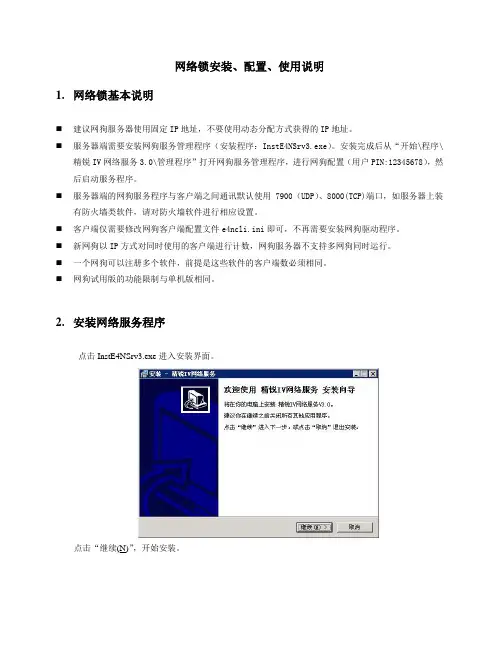
网络锁安装、配置、使用说明1.网络锁基本说明⏹建议网狗服务器使用固定IP地址,不要使用动态分配方式获得的IP地址。
⏹服务器端需要安装网狗服务管理程序(安装程序:InstE4NSrv3.exe)。
安装完成后从“开始\程序\精锐IV网络服务3.0\管理程序”打开网狗服务管理程序,进行网狗配置(用户PIN:12345678),然后启动服务程序。
⏹服务器端的网狗服务程序与客户端之间通讯默认使用7900(UDP)、8000(TCP)端口,如服务器上装有防火墙类软件,请对防火墙软件进行相应设置。
⏹客户端仅需要修改网狗客户端配置文件e4ncli.ini即可,不再需要安装网狗驱动程序。
⏹新网狗以IP方式对同时使用的客户端进行计数,网狗服务器不支持多网狗同时运行。
⏹一个网狗可以注册多个软件,前提是这些软件的客户端数必须相同。
⏹网狗试用版的功能限制与单机版相同。
2.安装网络服务程序点击InstE4NSrv3.exe进入安装界面。
点击“继续(N)”,开始安装。
定义安装目录、开始菜单快捷方式后,点击“继续(N)”。
如果以前已经安装过网狗服务程序,则会提示用户是否重新安装,如果需要重新安装点击“是(Y)”,然后点击“安装(I)”。
如果以前没有安装过网狗服务程序,则不会弹出提示,直接点击“安装(I)”。
安装完成后,点击“完成(F)”。
3.网络锁服务管理工具的使用第一步:启动网络服务程序从“开始\程序\精锐IV网络服务3.0\管理程序”打开网狗服务管理程序,如下图:第二步:锁参数设置点击菜单/管理/参数设置或工具栏中的设置按钮“”,用来设置服务的网络参数和网络锁的运行参数。
如下图:通常情况下,用户仅需要进行“锁参数设置”,如上图红框中所示。
设备ID:填入网络锁号。
例如网络锁上的打印内容为“A0866123-N”,填入“A0866123”即可。
用户PIN:填入“12345678”。
超时时长:默认600秒。
第三步:启动服务从菜单->管理->启动服务或点击工具栏的快捷按钮“”来启动服务。


精锐IV网络锁说明目录精锐IV网络锁说明 (1)1、安装加密锁驱动程序 (2)2、安装网络锁服务程序 (3)3、工具及配置文件说明 (5)3.1网络锁服务管理工具 (5)3.1.1添加主机 (5)3.1.2网络锁参数配置 (6)3.1.3使用服务管理程序 (8)3.2配置文件 (9)3.2.1管理配置文件 (9)3.2.2服务配置文件 (9)3.2.3客户端配置文件 (11)4、网络锁访问测试 (11)5、常见问题处理(FAQ) (13)附录 (16)1、检查服务器端的TCP、UDP端口是否被占用 (16)网络版可以允许多个软件的实例同时访问连接在服务器上的同一个加密锁,即对加密锁进行共享。
通过限制同时运行的客户端软件数目,可以达到对软件的使用进行控制的目的。
相对于单机版来说,网络版不仅需要保护软件不被非法复制,同时必须严格限制同时运行的软件数目。
1、安装加密锁驱动程序加密锁默认为有驱模式,需要安装驱动程序。
安装SDK 的过程会自动安装精锐IV 的设备驱动程序,在一些情况下您可能需要单独安装驱动程序(例如将整个SDK 复制到其它计算机中直接使用、发布您的软件),这时候您需要使用SDK中提供的驱动程序安装工具。
该工具位于%SDK%\Drivers 目录下,名称为“InstWiz3.exe”。
这是一个WIN32 可执行程序,可以接受以下命令行参数:♦/INSTALL 安装驱动程序(该选项为默认选项)♦/UNINSTALL 卸载驱动程序♦/NOGUI 不显示安装界面这些命令行参数可以组合使用,例如,您可以运行“InstWiz3.exe /uninstall /nogui”来隐式卸载设备驱动。
该工具也可以用来检测当前系统中精锐IV 设备驱动程序的安装情况:运行InstWiz3.exe,工具将自动检测并汇报驱动程序的安装情况。
有几种办法可以测试驱动程序是否安装成功:1. 插入精锐IV设备,检查硬件设备列表中是否出现正常的Senselock SenseIV v2.x设备(“设备管理器”Æ“智能卡阅读器”下);对于Windows98、Window2000 或更高版本,如果设备是第一次插入,系统会自动提示“找到新设备”并完成安装;2. 插入精锐IV设备,运行开发测试工具或者用户工具,看是否能成功访问设备;如果您对设备驱动程序的安装过程非常熟悉,您也可以选择手工的方式安装精锐IV 设备驱动。
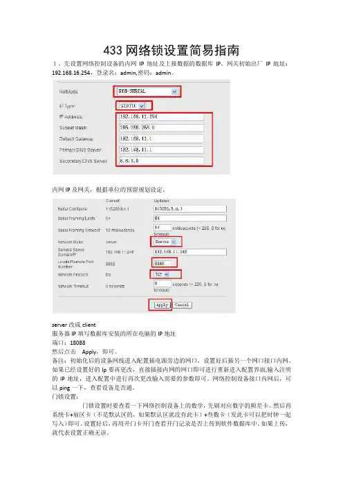
433网络锁设置简易指南
1、先设置网络控制设备的内网IP地址及上报数据的数据库IP。
网关初始出厂IP地址:192.168.16.254,登录名:admin,密码:admin。
内网IP及网关,根据单位的预留规划设定。
server改成client
服务器IP填写数据库安装的所在电脑的IP地址
端口:18088
然后点击Apply,即可。
备注:初始化后的设备网线进入配置插电源旁边的网口,设置好后插另一个网口接口内网。
如果已经设置好的Ip要再更改,直接插接内网的网口即可进行重新进入配置界面,输入注明的IP地址,进入配置中进行再次更改输入需要的参数即可。
网络控制设备接口内网后,可以ping一下,查看设备是否通。
门锁设置:
门锁设置时要查看一下网络控制设备上的数学,先刷对应数字的频差卡。
然后再系统卡+扇区卡(不是默认区的,如果默认区就没有此卡)+叁数卡(发此卡可以把时钟一起写入)即可。
设置好后,再用开门卡开门查看开门记录是否上传到软件数据库中。
如果上传,就代表设置正确无误。

腾达最新的11N无线路由加密设置方法[核芯显卡混战创奇迹-华硕A43E 评测篇][回复][引用][本帖链接][只看该作者]陈年老酒板凳 陈年老酒发表于 2010-03-30 14:54:32 最后由 陈年老酒 于 2010-03-30 18:45:26 修改 蹭网横行,TP-LINK 无线产品如何防蹭网近期,一种宣称能够破解无线密码、偷偷连接到别人的无线路由器实现“免费”上网的“蹭网卡”在市场上炒得沸沸扬扬,“卡王”、“卡皇”、“卡神”层出不穷,卖得火热,很多用户也经不住这种“免费午餐”的***,加入到“蹭网”的行列。
与此同时,不少用户也开始报怨自己使用无线路由器上网很慢,怀疑是被人“蹭网”了。
“蹭网卡”是一种什么样的产品,而我们又该如何保护自己的无线网络安全呢?∙关注∙1粉丝 ∙436帖子加为关注 ∙主∙户名:z p h x ∙衔:太平洋舰队中认识蹭网卡“蹭网卡”是一种Wifi 无线局域网网卡,和标准的无线网卡相比,主要有以下特点: 1、发射功率大中国无委会规定天线增益低于10dBi 的2.4GHz 无线局域网产品等效全向辐射功率(EIRP)必须小于或等于100mW ,欧盟CE 认证标准也规定2.4GHz 无线局域网产品的等效全向辐射功率(EIRP)要小于或等于100mW ,所以标准的无线路由器和无线网卡发射功率一般都在50-100mW 之间,而“蹭网卡”发射功率一般都在800mW 以上,是标准无线产品的十几倍,和手机相当,辐射较强,属于严重超标产品,长时间、近距离使用会影响到人体健康。
2、能破解密码这类网卡一般都配有BT3/BT4等***,但只能破解WEP 加密,对于使用WPA-PSK/WPA2-PSK AES 加密的无线路由器却无能为力,所以只要选择恰当的加密方法,完全可以防范恶意蹭网。
如何防蹭网了解了“蹭网卡”的特点,防蹭网就比较容易了。
TP-LINK 所有的无线路由器都支持WPA-PSK/WPA2-PSK 安全机制,用户只要在设置路由器时,选择WPA-PSK/WPA2-PSK 安全类型,并指定加密方法为AES 加密,即可有效保护无线网络的安全,防止蹭网一族的盗用。

During installation, you will temporarily lose Wi-Fi on connected devices.Be patient. Some changes can take over 5 minutesfor the technology to fully update.Turn off and disconnect any Wi-Fi extenders in the home.Follow each step carefully and check it off once it’sfully completed.Step 2Let’s set up your Orbi router and Orbi satellite.Step 3Time to download the Orbi app.Step 4Integrate Orbi with yourFios Internet and TV network.A. Open a browser on your phone and type B. S ign in to your Orbi account using the user name adminand admin password you chose during step 4 E.C. S elect the ADVANCED tab > Advanced Setup >Router/AP ModeD. Select the AP Mode check boxE. C lick the Apply button (at the top) to save the changes.Your Orbi will reboot. Once the reboot is complete(a minute or two after the ring light goes off), yourOrbi will be in AP mode. You can now close theOrbilogin web page.Congratulations, you’vesuccessfully installedyour Netgear Orbi routerand satellite.Step 1Orbi will take over your Wi-Fi, so let’s turn off the Wi-Fi on your Fios router (choose your model below).Fios Quantum GatewayUse one of the following methods:Use the My Fios appA. Select Internet from the main screenB. U nder My Networks, tap Enabled foryour Wi-Fi network and switchEnable Private Wi-Fi Access to OFF.C. R epeat for the other Wi-Fi networklisted (2.4 GHz or 5 GHz)D. Repeat for any guest Wi-Fi network listedE. T he Wi-Fi indicator light on your Fios routershould be off.OrYou can also turn off your Fios® router Wi-Fi by logging in to your account at /myverizon. If you use a computer, we recommend connecting to your router with an Ethernet cable.Fios Advanced Wi-Fi Router and other modelsA. Open a browser and enter 192.168.1.1B. Sign in with your router name and password- Router name: admin- R outer password: The default password can be found on your router’s labelN ote: If you change the default password, use your new passwordC. Go to Quick Links on the leftD. S elect Change Wireless Settings, then change the button to turn wireless offE. T he Wi-Fi indicator light on your Fios router shouldbe off.Fios Quantum GatewayDownload My Fios appFios Advanced Wi-Fi Router A. U nplug power from your Fios router and wait 10seconds before plugging it back in.B. U se the Ethernet cable included in your Orbi kit toconnect your Fios router to the yellow internet porton your Orbi router.C. U se the power plug included in your Orbi kit to connectyour Orbi router to a power source. The power LED onthe back of the Orbi router will be green. If the powerLED does not light green, press the power on/off button.D. W ait for the Orbi router’s ring LED to light solid whiteand then pulse white. Once the router’s ring light issolid white or goes off, it is ready. If it lights solidmagenta, it’s not connecting to the internet.E. C onnect the Orbi satellite to a power source. If thepower LED on the back of the Orbi satellite does notlight, press the power on/off button.F. W ait for the Orbi satellite’s ring LED to light solid white,then pulse white. Note: This can take up to 6 minutes.The Orbi satellite’s ring LED might turn solid magentafor up to one minute while the satellite attempts to syncwith the Orbi router.G. A fter the Orbi satellite’s ring LED completes its whitepulsing, it lights one of the following colors for at least20 seconds:•S olid blue: The connection between the Orbi routerand Orbi satellite is good.•S olid amber: The connection between the Orbirouter and Orbi satellite is fair. Consider movingthe Orbi satellite closer to the Orbi router.•S olid magenta: The Orbi satellite cannot connectto the Orbi router. Move the Orbi satellite closerto the Orbi router.A. S earch for and download the NETGEAR Orbi app inthe Apple App Store or Google Play Store.B. C onnect your mobile device to the Orbi using a Wi-Ficonnection. Use the Orbi Wi-Fi network name (SSID)and password located on the bottom label of the Orbirouter or Orbi satellite (they are also on the clear plasticring at the top of a new Orbi router).C. L aunch the Orbi app. Select New System Setup, andclick Next or follow the instructions in the app until youget to Create Wi-Fi Network. Note: No need to unplugyour Fios router.D. I MPORTANT - Change the Wi-Fi Network Name (SSID)and the Network Key (Password).I f you had more than one SSID on your Fios router,choose the one you use the most. It maymatch the default on the side of your Fios router, or acustomized name you entered. You needto be EXACT in your typing (case and space-sensitive).N ote: Be patient. Once you select NEXT please wait atleast 3 minutes for Orbi to restartinternet with the new SSID.E. O n the Log In to Your Orbi screen, please select anadmin password and write it down. Note the adminusername is admin. You will be using these again shortly.Guest Wi-Fi Users: You can set up guest Wi-Fi in the Orbiapp. You can use the same router name and password youuse today on your Fios router guest Wi-Fi so guests won’thave to enter new Wi-Fi credentials.You’re almost done!。
冠林联网型门禁系统操作说明-CAL-FENGHAI-(2020YEAR-YICAI)_JINGBIAN联网型门禁系统软件安装及操作手册本手册于2002年03月23日修订完成,2002年04月20日更新版权所有,XXXX年XX月XX日冠林科技地址: 福州市五一中路88号平安大厦16层电话:传真:邮件:网站: 目录1系统概述1.1概述非常感谢您选用冠林科技的联网型门禁系统。
本系统分为计算机管理软件及硬件设备2部分,本手册仅介绍计算机管理软件部分的软件安装、软件设置、日常操作及维护等,可供工程安装配置人员、系统管理维护人员及系统操作人员使用。
硬件的安装和使用操作请参见其它相关文档。
本软件采用扁平化的设计模型,界面美观,层次感强,易于操作。
分类设置系统参数,参数逻辑清晰明了,容易理解。
具备灵活配置机制,用户可自定义网段及串口的关系,可自定义各种报警类型的声音等。
参数设置及信息监控采用图形与表格相结合,非常直观,一目了然。
本软件可运行在Window98(二版以上)、Windows 及Windows2000(建议用此操作系统)的操作系统上。
1.2系统组成联网型门禁系统主要由联网型门禁管理软件、Anet网络界面器、门禁控制器等组成。
其系统结构图如下所示:图 1.2-1 联网型门禁系统组成结构如图,门禁控制器提供5个接口:一个门磁、一个电锁、一个出门按钮、一个I输入口和一个O输出口。
2名词解释2.1基本概念2.1.1网段门禁控制器是通过界面器与计算机串口进行通讯的,一个串口只能接一个界面器。
与同一个界面器相连的控制器我们称它为同一网段的控制器。
管理软件中可设置4个网段,对应的控制器地址分别以001、002、003、004开头。
一个网段对应一个串口号,一般PC 机有两个串口,所以,一个网段必须对应一个串口号。
例:假设网段1对应是串口2(COM2)时,网段1的界面器必须接到电脑的串口2上,该网段的控制器地址均以001开头。
Firewall Defaults, Public Server Rule,and Secondary WAN IP AddressThis quick start guide provides the firewall defaults and explains how to configure some basic firewall rules for the ProSafe Wireless-N 8-Port Gigabit VPN Firewall FVS318N to get you up and running fast. For information about more complicated firewall features, and for complete configuration steps, see the Reference Manual. This quick start guide contains the following sections:•Default Firewall Rules and General Security Settings•Create a Firewall Rule for a Public Server•Create a Firewall Rule for a Secondary WAN IP Address•For More InformationNote: For more information about the topics covered in this guide, visit theFVS318N support website at . You willalso find the Reference Manual at the support website.Default Firewall Rules and General Security SettingsThe default firewall rules and general security settings should work well for most small business networks, and you do not need change these settings for correct functioning of the wireless VPN firewall. The default settings are listed in the following table.Table 1. Default firewall rules and general security settingsSecurity Feature Default Behavior Reference Section for MoreInformation in Chapter 5,“Firewall Protection,” of theReference ManualDefault inbound LAN WAN firewall rule (communications coming in from the Internet)All traffic from theWAN is blocked,except in responseto LAN requests.• “Overview of Rules to Block orAllow Specific Kinds of Traffic”• “Configure LAN WAN Rules”Default outbound LAN WAN firewall rule (communications from the LAN to the Internet)All traffic from the LAN is allowed.Inbound and outbound DMZ WAN firewall rules None• “Overview of Rules to Block or Allow Specific Kinds of Traffic”• “Configure DMZ WAN Rules”Inbound and outbound LAN DMZ firewall rules None• “Overview of Rules to Block or Allow Specific Kinds of Traffic”• “Configure LAN DMZ Rules”Respond to ping on WAN (Internet) ports Disabled “Attack Checks”Stealth mode (prevents responses to port scans from the WAN)Enabled TCP flood (allows all invalid TCP packets to be dropped as protection from a SYN flood attack)EnabledUDP flood (prevents more than 20 simultaneous, active UDP connections from a single device on the LAN)Enabled Respond to ping on LAN portsDisabled IPv4 VPN pass-through for IPSec in NAT mode Enabled IPv4 VPN pass-through for PPTP in NAT mode Enabled IPv4 VPN pass-through for L2TP in NAT mode Enabled IPv6 VPN pass-through for IPSecEnabled Multicast pass-through for IGMP (allows multicast packets from the WAN to be forwarded to the LAN)DisabledJumbo frames (allow multiple smaller packets to be combined into a single larger packet)1Disabled Session limitsDisabled “Set Limits for IPv4 Sessions”TCP expiration time-out without traffic 1800 seconds UDP expiration time-out without traffic 120 seconds ICMP expiration time-out without traffic 60 seconds Session Initiation Protocol (SIP) support for the Application Level Gateway (ALG)Disabled “Manage the Application Level Gateway for SIP Sessions”Source MAC address filtering Disabled “Enable Source MAC Filtering”IP address-to-MAC address bindings Disabled “Set Up IP/MAC Bindings”Port triggering rulesNone“Configure Port Triggering”Table 1. Default firewall rules and general security settings (continued)Security FeatureDefault BehaviorReference Section for More Information in Chapter 5, “Firewall Protection,” of the Reference ManualCreate a Firewall Rule for a Public ServerBy default, all access from outside is blocked, except responses to requests from LAN users. If you host a public web or FTP server on your LAN, you can define a rule to allow inbound web (HTTP) or FTP requests from any outside IP address to the IP address of your web or FTP server at any time of the day.To configure a public server:1. Select Security > Firewall . The Firewall submenu tabs display with the LAN WANRules screen for IPv4 in view.2. Click the Add table button under the Outbound Services table. The Add LAN WANOutbound Service screen for IPv4 displays. The following screen shows an example for a public web server:Universal Plug and Play (UPnP)Disabled “Configure Universal Plug and Play”Bandwidth profiles None “Create Bandwidth Profiles”Content filtering Disabled “Configure Content Filtering”Proxy server blocking Disabled Java applets blocking Disabled ActiveX controls blocking Disabled Cookies blocking Disabled Blocked keywords None Trusted domainsAll domains1. Jumbo frames are supported on ports 1, 2, 3, and 4 only.Table 1. Default firewall rules and general security settings (continued)Security FeatureDefault BehaviorReference Section for More Information in Chapter 5, “Firewall Protection,” of the Reference Manual\Figure 1.3. Configure the settings as explained in the following table. The fields that are not mentionedare not required.Table 2. Screen settings for adding public server#Setting DescriptionService From the drop-down list, select HTTP for a web server or FTP for an FTP server.ActionFrom the drop-down list, select ALLOW always .●Send to Lan ServerFrom the drop-down list, Single Address .❍Start (under Send to Lan Server)Type the IP address of the web or FTP server on your LAN.⏹WAN Destination IP Address From the drop-down list, select Broadband for the WAN interface.☐WAN UsersFrom the drop-down list, select Any .●❍⏹☐4. Click Apply to save your changes. The new rule is added to the LAN WAN Rules screenand is automatically enabled.Create a Firewall Rule for a Secondary WAN IP Address By default, all access from outside is blocked, except responses to requests from LAN users.As an added security measure, you can configure a secondary WAN IP address to which inbound web (HTTP) requests from any outside IP address can be directed at any time of the day.To configure a secondary WAN IP address:1. Select Security > Firewall. The Firewall submenu tabs display with the LAN WANRules screen for IPv4 in view.2. Click the Add table button under the Outbound Services table. The Add LAN WANOutbound Service screen for IPv4 displays. The following screen shows an example for a secondary WAN IP address:\Figure 2.●❍⏹☐☐3. Configure the settings as explained in the following table. The fields that are not mentionedare not required.4. Click Apply to save your changes. The new rule is added to the LAN WAN Rules screenand is automatically enabled.For More InformationChapter 5, “Firewall Protection,” of the Reference Manual provides information about the following security topics:•Overview of rules to block or allow specific kinds of traffic •Configuring LAN WAN rules •Configuring DMZ WAN rules •Configuring LAN DMZ rules •Configuring other firewall features•Services, bandwidth profiles, and QoS profiles •Configuring content filtering•Setting a schedule to block or allow specific traffic •Enabling source MAC filtering •Setting up IP/MAC bindings •Configuring port triggering•Configuring universal Plug and Play (UPnP)Table 3. Screen settings for a adding secondary WAN IP address#Setting DescriptionService From the drop-down list, select HTTP for a web server or FTP for an FTP server.ActionFrom the drop-down list, select ALLOW always .●Send to Lan ServerFrom the drop-down list, Single Address .❍Start (under Send to Lan Server)Type the IP address of the web or FTP server on your LAN.⏹WAN Destination IP AddressFrom the drop-down list, select Other Public IP Address for the WAN interface.☐Start (under WAN Destination IP Address)Type the IP address of the secondary WAN address.☐WAN UsersFrom the drop-down list, select Any .。
路由器配置锁功能的使用说明1.登录路由器管理界面:打开浏览器,输入路由器的默认IP地址(一般为192.168.1.1或192.168.0.1),按回车键进入路由器登录界面。
输入默认的用户名和密码进行登录。
2.寻找并设置配置锁选项:在登录后的路由器管理界面中,寻找“配置锁”或类似的选项,一般在安全设置或系统设置中。
点击进入配置锁设置页面。
3.设置配置锁密码:在配置锁设置页面中,一般会有一个开关用于启用或禁用配置锁功能。
如果该功能未开启,点击开关进行启用。
4.设置配置锁密码:在启用配置锁功能之后,需要设置一个密码来限制用户对路由器进行配置。
在配置锁设置页面中,输入一个强密码,并进行确认。
5.设置提示问题:有些路由器配置锁功能允许设置提示问题,以便用户在忘记密码时可以通过提示问题来找回密码。
在设置页面中,设置一个问题,并填写答案。
6.保存设置:在完成密码和提示问题的设置后,点击“保存”或“应用”按钮,将设置保存到路由器中。
7.测试配置锁功能:重新启动路由器或将其断电重启,然后尝试登录路由器管理界面。
输入错误的密码,或者不提供提示问题的正确答案,应该无法登录成功。
8.更改或找回密码:如果有需要更改密码,可以再次登录到配置锁设置页面,输入当前密码后修改密码。
如果忘记密码时,可以通过正确回答提示问题来找回密码。
配置锁功能对保护路由器和网络安全非常重要,因此在使用路由器时应该及时设置配置锁密码,并定期更改密码,避免使用弱密码。
另外,不要将配置锁密码泄露给他人,并妥善保管提示问题的答案,以防落入他人手中。
步骤1配置广联达网络锁服务器**步骤1:配置广联达网络锁服务器**配置广联达网络锁服务器是一个多步骤的过程,需要按照以下步骤进行操作:1.**购买广联达网络锁服务器**:首先,您需要购买一台广联达网络锁服务器。
这通常可以通过广联达公司的官方网站或授权的经销商进行购买。
确保选择适合您需求的型号和规格。
2.**准备服务器安装环境**:在配置服务器之前,您需要为其提供一个合适的安装环境。
选择一个干燥、通风良好的房间,并确保它与其他设备保持适当的空间。
3.**安装服务器硬件**:将服务器放置在选择的房间中,并根据硬件安装指南连接所有必要的电缆和设备。
这可能包括电源线、网线、显示器、键盘和鼠标等。
4.**设置服务器引导程序**:在服务器上启动时,您需要设置引导程序。
这通常包括设置引导顺序、启用硬件虚拟化支持、配置BIOS设置等。
按照服务器和操作系统的说明手册进行设置。
5. **安装操作系统**:根据您的需求选择合适的操作系统,并按照操作系统的安装指南进行安装。
根据需要,您可以选择安装Windows Server、Linux以及其他适合的操作系统。
7.**配置广联达网络锁服务器**:安装完成后,您需要配置广联达网络锁服务器以满足您的需求。
这可能包括设置网络连接、配置访问权限、创建用户账户等。
详细的配置方法可以在广联达公司的官方网站或用户手册中找到。
8.**测试网络锁服务器的功能**:一旦服务器配置完成,您应该进行功能测试以确保一切正常工作。
这包括验证网络连接、用户权限、许可证安装等。
如果发现任何问题,可以参考广联达公司的技术支持文档或寻求他们的技术支持。
9.**备份和维护**:配置完成后,需要定期备份服务器的数据以防止数据丢失。
同时,需要进行定期的维护工作,如检查硬件状态、更新软件等。
10.**提供培训和支持**:最后,您应该提供培训和支持给使用该网络锁服务器的用户。
解释如何使用服务器以及如何解决一些常见问题,可以帮助用户更好地使用和管理服务器。
超級網管使用手冊1說明.............................................................................................................................1 2網路設定 (2)2.1 使用Windows XP..........................................................................................2 2.2 使用Window Vista.........................................................................................7 2.3 使用 Mac.....................................................................................................10 3其它資訊. (14)1說明宿舍網路是共用的網路環境宿舍網路是共用的網路環境,,非常容易發生非常容易發生互互搶頻寛搶頻寛、、電腦中毒電腦中毒。
「。
「超級網超級網管」可以將上述問題決解可以將上述問題決解,,讓用戶像是在家用中華電信ADSL 上網上網,,不受鄰居的干擾干擾。
如果您的電腦在家中已經是用ADSL 撥號上網撥號上網,,在這裡只要把撥接帳號和密碼都改成碼都改成 888 888 888 ,,就可以上網了就可以上網了。
2網路設定2.1 使用Windows XP步驟1: 點選點選「「開始開始」」→「連線到連線到(T)(T)(T)」」→「顯示所有連線顯示所有連線(S)(S)(S)」。
」。
步驟2: 在「網路工作網路工作」」→「建立一個新連線建立一個新連線」。
」。
步驟3: 在「歡迎使用新增連線精靈歡迎使用新增連線精靈」」→「下一步下一步(N)(N)(N)」。
1、安装服务:
运行InstE4NSrv3.exe根据提示输入路径自动安装服务。
2、网络锁服务管理程序:
(1)启动安装路径下tools目录下的e4nmgr.exe程序启动服务管理工具,点击“管理->参数设置”选项,如下图所示:
(2)对服务端网络进行设置,其中:TCP端口= UDP端口+ 100,锁参数设置选项中的设备ID必须为“south”,用户PIN是“nfchcass”
3、设置客户端配置文件
在每个客户机都要配置e4ncli.ini文件,该文件在CASS的SYSTEM目录下:
[NET_CONFIG]
HOSTADDR=192.168.5.38 //服务器IP地址
TCPPORT=8200 //TCP端口,依照服务管理程序的配置
UDPPORT=8100 //UDP端口,依照服务管理程序的配置
DEVELOPERID=south //固定不变
4、启动服务:
(1)点击“管理->启动服务”或者直接点击服务管理工具界面上的“√”按钮
(2)点击“文件->连接”按钮,显示连接成功,如下图所示:
如连接不成功,可插拔狗一次然后再试。