焊缝缺陷图片
- 格式:doc
- 大小:597.00 KB
- 文档页数:9

焊接缺陷,探伤图解(收藏)一起学习,共同进步!先看18张很清晰的焊接缺陷图谱,身边搞焊接的朋友和搞探伤的朋友们应该人手一份。
万分感谢将这篇文章分享给我的同仁另外总结了一些常见焊接缺陷产生的原因、危害及防止措施!文章结尾蓝色字体内容更精彩!先看这几张图片,射线探伤底片结合横切面示意图,便于理解学习,拿出来分享给朋友们!1、weld01(High Low、高低)2、welld02(IncompleteRootFusion、根部未熔合)3、welld03(InsuffucientReinforcement、增强高)4、welld04(Excess RootPenetration、根部焊瘤)5、welld05(ExternalUndercut、外部咬肉)6、welld06(InternalUndercut、内部咬肉)7、welld07(RootConcavity、根部凹陷)8、welld08(BurnThrough、烧穿)9、welld09(Isolated SlagInclusion、单个的夹渣)10、welld10(WagonTrack Slag Line、线状夹渣)11、welld11(InterrunFusion、内部未熔合)12、welld12(Lack ofSidewallFusion、内侧未熔合)13、welld13(Porosity、气孔)14、welld14(Cluster Porosity、链状气孔)15、welld15(HollowBead、夹珠)16、welld16(Transverse Crack、横向裂纹)17、welld17(CenterlineCrack、中心线裂纹)18、welld18(RootCrack、根部裂纹)常见焊接缺陷产生原因、危害及防止措施一、焊接缺陷的分类焊接缺陷可分为外部缺陷和内部缺陷两种1.外部缺陷1)外观形状和尺寸不符合要求;2)表面裂纹;3)表面气孔;4)咬边;5)凹陷;6)满溢;7)焊瘤;8)弧坑;9)电弧擦伤;10)明冷缩孔;11)烧穿;12)过烧。

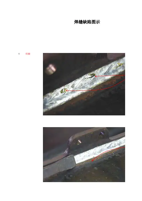
焊缝缺陷图示1焊鳞
2-气孔
修复方法:打磨去除该段焊缝,重新焊接。
3
-
弧坑针状气孔
打磨去除此部分
修复方法:打磨去除该段焊缝,重新焊接。
4-气孔(砂眼)
修复方法:打磨去除所有影响焊缝,重新焊接。
5-
缩孔
打磨去除此部分
修复方法:打磨去除所有影响焊缝,重新焊接。
6-端部裂纹/焊缝裂纹
修复方法:打磨去除所有影响焊缝,重新焊接。
7-不良焊缝外观
修复方法:重新焊接。
8
- 焊瘤及飞边重新焊接部分
修复方法:打磨,重新焊接。
9-咬边
修复方法:重新焊接。
10-咬边
修复方法:重新焊接。
11-焊缝不均匀
修复方法:重新焊接。
12‘-不良外观
修复方法:重新焊接。
13‘-不良外观
修复方法:重新焊接。
14‘-不良外观
焊鳞
去除焊鳞后焊缝表面。
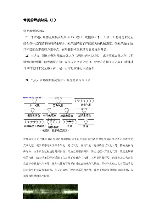
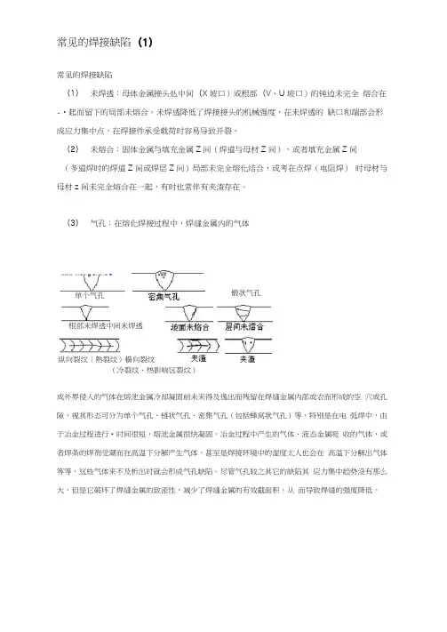
常见的焊接缺陷(1)常见的焊接缺陷(1)未焊透:母体金属接头处中间(X坡口)或根部(丫、U坡口)的钝边未完全熔合在一起而留下的局部未熔合。
未焊透降低了焊接接头的机械强度,在未焊透的缺口和端部会形成应力集中点,在焊接件承受载荷时容易导致开裂。
(2)未熔合:固体金属与填充金属之间(焊道与母材之间),或者填充金属之间(多道焊时的焊道之间或焊层之间)局部未完全熔化结合,或者在点焊(电阻焊)时母材与母材之间未完全熔合在一起,有时也常伴有夹渣存在。
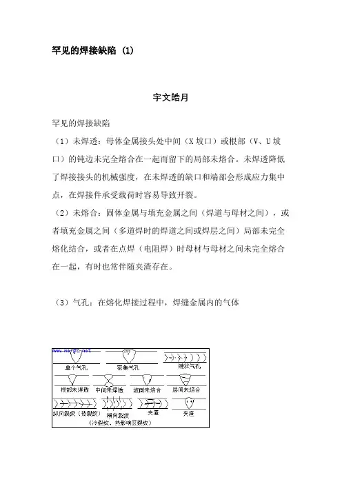
(3)气孔:在熔化焊接过程中,焊缝金属内的气体或外界侵入的气体在熔池金属冷却凝固前未来得及逸出而残留在焊缝金属内部或表面形成的空穴或孔隙,视其形态可分为单个气孔、链状气孔、密集气孔(包括蜂窝状气孔)等,特别是在电弧焊中,由于冶金过程进行时间很短,熔池金属很快凝固,冶金过程中产生的气体、液态金属吸收的气体,或者焊条的焊剂受潮而在高温下分解产生气体,甚至是焊接环境中的湿度太大也会在高温下分解出气体等等,这些气体来不及析出时就会形成气孔缺陷。
尽管气孔较之其它的缺陷其应力集中趋势没有那么大,但是它破坏了焊缝金属的致密性,减少了焊缝金属的有效截面积,从而导致焊缝的强度降低。
某钢板对接焊缝X射线照相底片V型坡口,手工电弧焊,未焊透某钢板对接焊缝X射线照相底片V型坡口,手工电弧焊,密集气孔(4)夹渣与夹杂物:熔化焊接时的冶金反应产物,例如非金属杂质(氧化物、硫化物等)以及熔渣,由于焊接时未能逸出,或者多道焊接时清渣不干净,以至残留在焊缝金属内,称为夹渣或夹杂物。
视其形态可分为点状和条状,其外形通常是不规则的,其位置可能在焊缝与母材交界处,也可能存在于焊缝内。
另外,在采用鸨极氩弧焊打底+手工电弧焊或者鸨极氩弧焊时,鸨极崩落的碎屑留在焊缝内则成为高密度夹杂物(俗称夹鸨)。
W18Cr4V (高速工具钢)-45钢棒对接电阻焊缝中的夹渣断口照片钢板对接焊缝X射线照相底片V型坡口,手工电弧焊,局部夹渣钢板对接焊缝X射线照相底片V型坡口,手工电弧焊,两侧线状夹渣钢板对接焊缝X射线照相底片V型坡口,鸨极氩弧焊打底+手工电弧焊,夹鸨(5)裂纹:焊缝裂纹是焊接过程中或焊接完成后在焊接区域中出现的金属局部破裂的表现。
常见的焊接缺陷(1)常见的焊接缺陷(1) 未焊透:母体金属接头处中间(X 坡口)或根部(V 、U 坡口)的钝边未完全 熔合在-•起而留下的局部未熔合。
未焊透降低了焊接接头的机械强度,在未焊透的 缺口和端部会形成应力集中点,在焊接件承受载荷时容易导致开裂。
(2) 未熔合:固体金属与填充金属Z 间(焊道与母材Z 间),或者填充金属Z 间(多道焊时的焊道Z 间或焊层Z 间)局部未完全熔化结合,或考在点焊(电阻焊) 时母材与母材z 间未完全熔合在一起,有时也常伴有夹渣存在。
(3) 气孔:在熔化焊接过程中,焊缝金属内的气体(冷裂纹、热影响区裂纹)或外界侵入的气体在熔池金属冷却凝固前未来得及逸出而残留在焊缝金属内部或农而形成的空 穴或孔隙,视其形态可分为单个气孔、链状气孔、密集气孔(包括蜂窝状气孔)等,特别是在电 弧焊中,由于冶金过程进行•时间很短,熔池金属很快凝固,冶金过程中产生的气体、液态金属吸 收的气体,或者焊条的焊剂受潮而在高温下分解产生气体,甚至是焊接环境中的湿度太人也会在 高温下分解出气体等等,这些气体来不及析出时就会形成气孔缺陷。
尽管气孔较之其它的缺陷其 应力集中趋势没有那么大,但是它破坏了焊缝金属的致密性,减少了焊缝金属的有效截面积,从 而导致焊缝的强度降低。
根部未焊透中间未焊透纵向裂纹〔熱裂纹)横向裂纹单个气孔 锻状气孔某钢板对接焊缝X射线照相底片V型坡口,手工电弧焊,未焊透某钢板对接焊缝X射线照相底片V型坡口,手工电弧焊,密集气孔(4)夹渣与夹杂物:熔化焊接时的冶金反应产物,例如非金属杂质(氧化物、硫化物等)以及熔渣,由于焊接时未能逸出,或者多道焊接时清渣不干净,以至残留在焊缝金属内,称为夹渣或夹杂物。
视其形态可分为点状和条状,其外形通常是不规则的,其位置可能在焊缝与母材交界处,也可能存在于焊缝内。
另外,在采用餌极氮弧焊打底+手工电弧焊或者钩极氮弧焊吋,钩极崩落的碎屑留在焊缝内则成为高密度夹杂物(俗称夹鸽)。
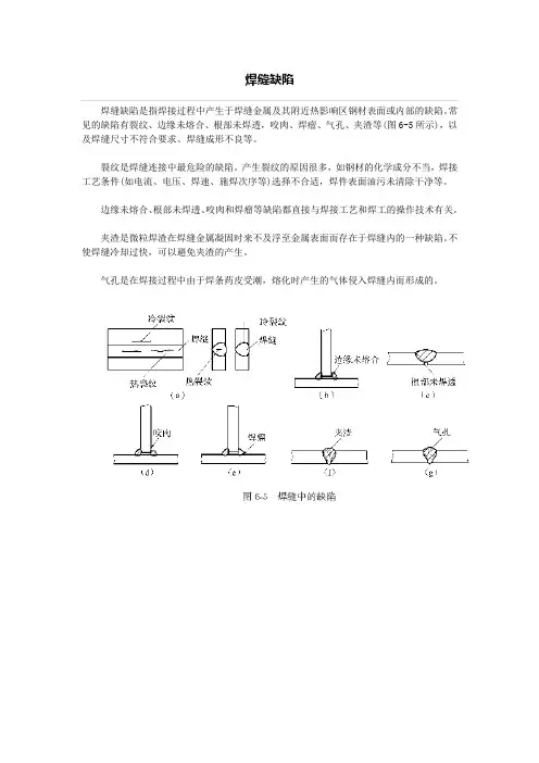
焊缝缺陷
焊缝缺陷是指焊接过程中产生于焊缝金属及其附近热影响区钢材表面或内部的缺陷。
常见的缺陷有裂纹、边缘未熔合、根部未焊透,咬肉、焊瘤、气孔、夹渣等(图6-5所示),以及焊缝尺寸不符合要求、焊缝成形不良等。
裂纹是焊缝连接中最危险的缺陷。
产生裂纹的原因很多,如钢材的化学成分不当,焊接工艺条件(如电流、电压、焊速、施焊次序等)选择不合适,焊件表面油污未清除干净等。
边缘未熔合、根部未焊透、咬肉和焊瘤等缺陷都直接与焊接工艺和焊工的操作技术有关。
夹渣是微粒焊渣在焊缝金属凝固时来不及浮至金属表面而存在于焊缝内的一种缺陷。
不使焊缝冷却过快,可以避免夹渣的产生。
气孔是在焊接过程中由于焊条药皮受潮,熔化时产生的气体侵入焊缝内而形成的。
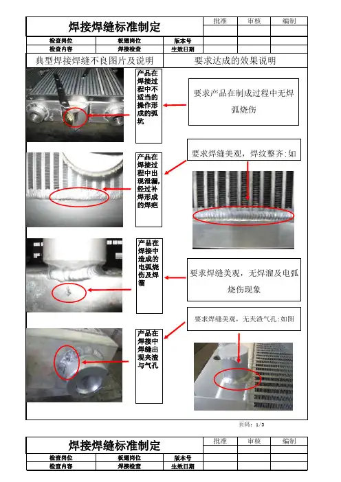
批准审核编制版本号生效日期页码:1/3批准审核编制版本号生效日期焊接焊缝标准制定典型焊接焊缝不良图片及说明要求达成的效果说明检查岗位检查内容板翅岗位焊接检查焊接焊缝标准制定检查岗位板翅岗位检查内容焊接检查要求产品在制成过程中无焊弧烧伤要求焊缝美观,焊纹整齐:如产品在焊接过程中不适当的操作形成的弧坑产品在焊接过程中出现泄漏,经过补焊形成的焊疤产品在焊接中造成的电弧烧伤及焊溜要求焊缝美观,无焊溜及电弧烧伤现象出现夹渣与气孔要求焊缝美观,无夹渣气孔:如图产品在焊接中焊缝出现夹渣与气孔页码:2/3批准审核编制版本号生效日期焊接焊缝标准制定检查岗位板翅岗位典型焊接焊缝不良图片及说明氩弧焊焊接事项检查内容焊接检查要求达成的效果说明产品在焊接中出现的咬边现象要求焊缝均匀,无焊接咬边现象.如图产品在焊接中出现焊纹不均匀现象要求焊缝均匀.如图产品在焊接中出现翅片烧损现象要求焊缝均匀.美观.焊透无气孔产品在焊接过程中出现未焊透,未熔合现象.焊前准备1.根据焊接位置,焊2.去除焊接位置两3.根据图纸.工艺要4.检查所用设备是焊接注意事项1.焊接前,在废钢板2.在引弧板或焊接3.防止地线,电缆4.防止焊接过程中5.受压元件角焊缝6.接弧处应保证焊7.焊后自检.焊缝表焊接缺陷:焊接缺陷可分为电弧烧伤.表面气孔,和气孔等.焊接缺陷焊接焊缝检验标准要求焊缝表面过度,不能有锐角返修:表面的焊页码:3/3。
罕见的焊接缺陷 (1)宇文皓月罕见的焊接缺陷(1)未焊透:母体金属接头处中间(X坡口)或根部(V、U坡口)的钝边未完全熔合在一起而留下的局部未熔合。
未焊透降低了焊接接头的机械强度,在未焊透的缺口和端部会形成应力集中点,在焊接件承受载荷时容易导致开裂。
(2)未熔合:固体金属与填充金属之间(焊道与母材之间),或者填充金属之间(多道焊时的焊道之间或焊层之间)局部未完全熔化结合,或者在点焊(电阻焊)时母材与母材之间未完全熔合在一起,有时也常伴随夹渣存在。
(3)气孔:在熔化焊接过程中,焊缝金属内的气体或外界侵入的气体在熔池金属冷却凝固前未来得及逸出而残留在焊缝金属内部或概况形成的空穴或孔隙,视其形态可分为单个气孔、链状气孔、密集气孔(包含蜂窝状气孔)等,特别是在电弧焊中,由于冶金过程进行时间很短,熔池金属很快凝固,冶金过程中发生的气体、液态金属吸收的气体,或者焊条的焊剂受潮而在高温下分解发生气体,甚至是焊接环境中的湿度太大也会在高温下分解出气体等等,这些气体来不及析出时就会形成气孔缺陷。
尽管气孔较之其它的缺陷其应力集中趋势没有那么大,但是它破坏了焊缝金属的致密性,减少了焊缝金属的有效截面积,从而导致焊缝的强度降低。
某钢板对接焊缝X射线照相底片V型坡口,手工电弧焊,未焊透某钢板对接焊缝X射线照相底片V型坡口,手工电弧焊,密集气孔(4)夹渣与夹杂物:熔化焊接时的冶金反应产品,例如非金属杂质(氧化物、硫化物等)以及熔渣,由于焊接时未能逸出,或者多道焊接时清渣不干净,以至残留在焊缝金属内,称为夹渣或夹杂物。
视其形态可分为点状和条状,其外形通常是不规则的,其位置可能在焊缝与母材交界处,也可能存在于焊缝内。
另外,在采取钨极氩弧焊打底+手工电弧焊或者钨极氩弧焊时,钨极崩落的碎屑留在焊缝内则成为高密度夹杂物(俗称夹钨)。
W18Cr4V(高速工具钢)-45钢棒对接电阻焊缝中的夹渣断口照片钢板对接焊缝X射线照相底片V型坡口,手工电弧焊,局部夹渣钢板对接焊缝X射线照相底片V型坡口,手工电弧焊,两侧线状夹渣钢板对接焊缝X射线照相底片V型坡口,钨极氩弧焊打底+手工电弧焊,夹钨(5)裂纹:焊缝裂纹是焊接过程中或焊接完成后在焊接区域中出现的金属局部破裂的表示。
常见的焊接缺陷(1)常见的焊接缺陷(1) 未焊透:母体金属接头处中间(X 坡口)或根部(V 、U 坡口)的钝边未完全 熔合在一起而留下的局部未熔合。
未焊透降低了焊接接头的机械强度,在未焊透的缺口和端部会形成应力集中点,在焊接件承受载荷时容易导致开裂。
(2) 未熔合:固体金属与填充金属之间(焊道与母材之间),或者填充金属之间(多道焊时的焊道之间或焊层之间)局部未完全熔化结合,或者在点焊(电阻焊)时母材与母材之间未完全熔合在一起,有时也常伴有夹渣存在。
(3) 气孔:在熔化焊接过程中,焊缝金属内的气体或外界侵入的气体在熔池金属冷却凝固前未来得及逸岀而残留在焊缝金属内部或表面形成的空 穴或孔隙,视其形态可分为单个气孔、链状气孔、密集气孔(包括蜂窝状气孔)等,特别是在电 弧焊中,由于冶金过程进行时间很短, 熔池金属很快凝固, 冶金过程中产生的气体、 液态金属吸 收的气体,或者焊条的焊剂受潮而在高温下分解产生气体, 甚至是焊接环境中的湿度太大也会在高温下分解出气体等等,这些气体来不及析出时就会形成气孔缺陷。
尽管气孔较之其它的缺陷其应力集中趋势没有那么大, 但是它破坏了焊缝金属的致密性, 减少了焊缝金属的有效截面积,从""'横向裂纹 夹淹 (冷裂纹、热影响区裂纹) 纵向裂纹〔热裂纹)根部未焊透 中间未焊透 坡面未焙合 链狀气孔S 间未焙合夹渣而导致焊缝的强度降低。
某钢板对接焊缝X射线照相底片V型坡口,手工电弧焊,未焊透某钢板对接焊缝X射线照相底片V型坡口,手工电弧焊,密集气孔(4 )夹渣与夹杂物:熔化焊接时的冶金反应产物,例如非金属杂质(氧化物、硫化物等)以及熔渣,由于焊接时未能逸出,或者多道焊接时清渣不干净,以至残留在焊缝金属内,称为夹渣或夹杂物。
视其形态可分为点状和条状,其外形通常是不规则的,其位置可能在焊缝与母材交界处,也可能存在于焊缝内。
另外,在采用钨极氩弧焊打底+手工电弧焊或者钨极氩弧焊时,钨极崩落的碎屑留在焊缝内则成为高密度夹杂物(俗称夹钨)。
Radiograph Interpretation - WeldsIn addition to producing high quality radiographs, the radiographer must also be skilled in radiographic interpretation. Interpretation of radiographs takes place in three basic steps which are (1) detection, (2) interpretation, and (3) evaluation. All of these steps make use of the radiographer's visual acuity. Visual acuity is the ability to resolve a spatial pattern in an image. The ability of an individual to detect discontinuities in radiography is also affected by the lighting condition in the place of viewing, and the experience level for recognizing various features in the image. The following material was developed to help students develop an understanding of the types of defects found in weldments and how they appear in a radiograph.DiscontinuitiesDiscontinuities are interruptions in the typical structure of a material. These interruptions may occur in the base metal, weld material or "heat affected" zones. Discontinuities, which do not meet the requirements of the codes or specification used to invoke and control an inspection, are referred to as defects.General Welding DiscontinuitiesThe following discontinuities are typical of all types of welding.Cold lap is a condition where the weld filler metal does not properly fuse with the base metal or the previous weld pass material (interpass cold lap). The arc does not melt the base metal sufficiently and causes the slightly molten puddle to flow into base material without bonding.Porosity is the result of gas entrapment in the solidifying metal. Porosity can take many shapes on a radiograph but often appears as darkround or irregular spots or specks appearing singularly, in clusters or rows. Sometimes porosity is elongated and may have the appearance of having a tail This is the result of gas attempting to escape while the metal is still in a liquid state and is called wormhole porosity. All porosity is a void in the material it will have a radiographic density more than the surrounding area..Cluster porosity is caused when flux coated electrodes are contaminated with moisture. The moisture turns into gases when heated and becomes trapped in the weld during the welding process. Cluster porosity appear just like regular porosity in the radiograph but the indications will be grouped close together.Slag inclusions are nonmetallic solid material entrapped in weld metal or between weld and base metal. In a radiograph, dark, jagged asymmetrical shapes within the weld or along the weld joint areas are indicative of slag inclusions.Incomplete penetration (IP) or lack of penetration (LOP)occurs when the weld metal fails to penetrate the joint. It is one of the most objectionable weld discontinuities. Lack of penetration allows a natural stress riser from which a crack may propagate. The appearance on a radiograph is a dark area with well-defined, straight edges that follows the land or root face down the center of the weldment.Incomplete fusion is a condition where the weld filler metal does not properly fuse with the base metal. Appearance on radiograph: usually appears as a dark line or lines oriented in the direction of the weld seam along the weld preparation or joining area.Internal concavity or suck back is condition where the weld metal has contracted as it cools and has been drawn up into the root of the weld. On a radiograph it looks similar to lack of penetration but the line has irregular edges and it is often quite wide in the center of the weld image.Internal or root undercut is an erosion of the base metal next to the root of the weld. In the radiographic image it appears as a dark irregular line offset from the centerline of the weldment. Undercutting is not as straight edged as LOP because it does not follow a ground edge.External or crown undercut is an erosion of the base metal next to the crown of the weld. In the radiograph, it appears as a dark irregular line along the outside edge of the weld area.Offset or mismatch are terms associated with a condition where two pieces being welded together are not properly aligned. The radiographic image is a noticeable difference in density between the two pieces. The difference in density is caused by the difference in material thickness. The dark, straight line is caused by failure of the weld metal to fuse with the land area.Inadequate weld reinforcement is an area of a weld where the thickness of weld metal deposited is less than the thickness of the base material. It is very easy to determine by radiograph if the weld has inadequate reinforcement, because the image density in the area of suspected inadequacy will be more (darker) than the image density of the surrounding base material.Excess weld reinforcement is an area of a weld, which has weld metal added in excess of that specified by engineering drawings and codes. The appearance on a radiograph is a localized, lighter area in the weld. A visual inspection will easily determine if the weld reinforcement is in excess of that specified by the individual code involved in the inspection.Cracking can be detected in a radiograph only the crack is propagating in a direction that produced a change in thickness that is parallel to the x-ray beam. Cracks will appearas jagged and often very faint irregular lines. Cracks can sometimes appearing as "tails" on inclusions or porosity.Discontinuities in TIG weldsThe following discontinuities are peculiar to the TIG welding process. These discontinuities occur in most metals welded by the process including aluminum and stainless steels. The TIG method of welding produces a clean homogeneous weld which when radiographed is easily interpreted.Tungsten inclusions. Tungsten is a brittle and inherently dense material used in the electrode in tungsten inert gas welding. If improper welding procedures are used, tungsten may be entrapped in the weld. Radiographically, tungsten is more dense than aluminum or steel;therefore, it shows as a lighter area with a distinct outline on the radiograph.Oxide inclusions are usually visible on the surface of material being welded (especially aluminum). Oxide inclusions are less dense than the surrounding materials and, therefore, appear as dark irregularly shaped discontinuities in the radiograph.Discontinuities in Gas Metal Arc Welds (GMAW)The following discontinuities are most commonly found in GMAW welds.Whiskers are short lengths of weld electrode wire, visible on the top or bottom surface of the weld or contained within the weld. On a radiograph they appear as light, "wire like" indications.Burn through (icicles)results when too much heat causes excessive weld metal to penetrate the weld zone. Lumps of metal sag through the weld creating a thick globular condition on the back of the weld. On aradiograph, burn through appears as dark spots surrounded by light globular areas.。