焊接缺陷图谱
- 格式:ppt
- 大小:5.56 MB
- 文档页数:70
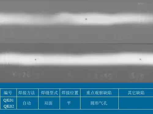
焊接工程上存在的质量通病(附图、原因、防治措施)第一篇:焊接工程上存在的质量通病(附图、原因、防治措施) 焊接工程上存在的质量通病凡是肉眼或低倍放大镜能看到的且位于焊缝表面的缺陷,如咬边(咬肉)、焊瘤、弧坑、表面气孔、夹渣、表面裂纹、焊缝位置不合理等称为外部缺陷;而必须用破坏性试验或专门的无损检测方法才能发现的内部气孔、夹渣、内部裂纹、未焊透、未溶合等称为内部缺陷。
但常见的多是焊后不清理焊渣和飞溅物以及不清理的焊疤。
1、焊缝尺寸不符规范要求1.1现象:焊缝在检查中焊缝的高度过大或过小;或焊缝的宽度太宽或太窄,以及焊缝和母材之间的过渡部位不平滑、表面粗糙、焊缝纵、横向不整齐,还有在角焊缝部位焊缝的下凹量过大。
1.2原因:1.2.1焊缝坡口加工的平直度较差,坡口的角度不当或装配间隙大小不均等而引起的。
1.2.2焊接中电流过大,使焊条熔化过快,控制焊缝成形困难,电流过小,在焊接引弧时会使焊条产生“粘合现象”,造成焊不透或焊瘤。
1.2.3焊工操作熟练程不够,运条方法不当,如过快或过慢,以及焊条角度不正确。
1.2.4埋弧自动焊过程,焊接工艺参数选择不当。
1.3防治措施1.3.1按设计要求和焊接规范的规定加工焊缝坡口,尽量选用机械加工以使坡口角度和坡口边缘的直线度和坡口边缘的直线度达到要求,避免用人工气割、手工铲削加工坡口。
在组对时,保证焊缝间隙的均匀一致,为保证焊接质量打下基础。
1.3.2通过焊接工艺评定,选择合适的焊接工艺参数。
1.3.3焊工要持证上岗,经过培训的焊工有一定的理论基础和操作技能。
1.3.4多层焊缝在焊接表面最后一层焊缝是,在保证和底层熔合的条件下,应采用比各层间焊接电流较小,并用小直径(φ2.0mm~3.0mm)的焊条覆面焊。
运条速度要求均匀,有节奏地向纵向推进,并作一定宽度的横向摆动,可使焊缝表面整齐美观。
2、咬边(咬肉)2.1现象:焊接时的电弧将焊缝边缘熔出的凹陷或沟槽没有得到熔化金属的补充而留下缺口。
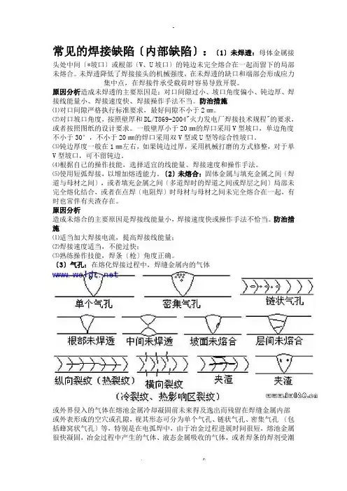
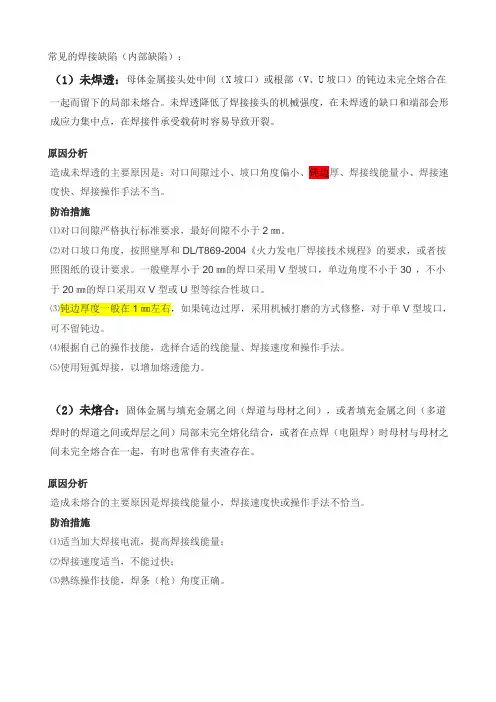
常见的焊接缺陷〔内部缺陷〕:〔1〕未焊透:母体金属接头处中间〔*坡口〕或根部〔V、U坡口〕的钝边未完全熔合在一起而留下的局部未熔合。
未焊透降低了焊接接头的机械强度,在未焊透的缺口和端部会形成应力集中点,在焊接件承受载荷时容易导致开裂。
原因分析造成未焊透的主要原因是:对口间隙过小、坡口角度偏小、钝边厚、焊接线能量小、焊接速度快、焊接操作手法不当。
防治措施⑴对口间隙严格执行标准要求,最好间隙不小于2㎜。
⑵对口坡口角度,按照壁厚和DL/T869-2004"火力发电厂焊接技术规程"的要求,或者按照图纸的设计要求。
一般壁厚小于20㎜的焊口采用V型坡口,单边角度不小于30°,不小于20㎜的焊口采用双V型或U型等综合性坡口。
⑶钝边厚度一般在1㎜左右,如果钝边过厚,采用机械打磨的方式修整,对于单V型坡口,可不留钝边。
⑷根据自己的操作技能,选择适宜的线能量、焊接速度和操作手法。
⑸使用短弧焊接,以增加熔透能力。
〔2〕未熔合:固体金属与填充金属之间〔焊道与母材之间〕,或者填充金属之间〔多道焊时的焊道之间或焊层之间〕局部未完全熔化结合,或者在点焊〔电阻焊〕时母材与母材之间未完全熔合在一起,有时也常伴有夹渣存在。
原因分析造成未熔合的主要原因是焊接线能量小,焊接速度快或操作手法不恰当。
防治措施⑴适当加大焊接电流,提高焊接线能量;⑵焊接速度适当,不能过快;⑶熟练操作技能,焊条〔枪〕角度正确。
〔3〕气孔:在熔化焊接过程中,焊缝金属内的气体或外界侵入的气体在熔池金属冷却凝固前未来得及逸出而残留在焊缝金属内部或外表形成的空穴或孔隙,视其形态可分为单个气孔、链状气孔、密集气孔〔包括蜂窝状气孔〕等,特别是在电弧焊中,由于冶金过程进展时间很短,熔池金属很快凝固,冶金过程中产生的气体、液态金属吸收的气体,或者焊条的焊剂受潮而在高温下分解产生气体,甚至是焊接环境中的湿度太大也会在高温下分解出气体等等,这些气体来不及析出时就会形成气孔缺陷。
本文源自:中国无损检测论坛weld-01 (High - Low、高-低)也叫错边welld-02 (Incomplete Root Fusion、根部未熔合)welld-03 (Insuffucient Reinforcement、内凹)welld-04 (Excess Root Penetration、根部焊瘤)(External Undercut、外部咬肉)welld-06(Internal Undercut、内部咬肉)welld-07(Root Concavity、根部凹陷) (Root Concavity、根部凹陷)welld-08(Burn Through、烧穿) (Burn Through、烧穿)welld-09(Isolated Slag Inclusion、单个的夹渣) (Isolated Slag Inclusion、单个的夹渣)Wagon Track - Slag Line、线状夹渣线状夹渣(Interrun Fusion、内部未熔合) (Interrun Fusion、内部未熔合)welld-12(Lack of Sidewall Fusion、内侧未熔合) (Lack of Sidewall Fusion、内侧未熔合)welld-13(Porosity、气孔) (Porosity、气孔)(Cluster Porosity、链状气孔) (Cluster Porosity、链状气孔)welld-15(Hollow Bead、夹珠) (Hollow Bead、夹珠)welld-16(Transverse Crack、横向裂纹) (Transverse Crack、横向裂纹)(Centerline Crack、中心线裂纹) (Centerline Crack、中心线裂纹)welld-18(Root Crack、根部裂纹) (Root Crack、根部裂纹)(Tungsten Inclusion)夹钨(Tungsten Inclusion)夹钨。
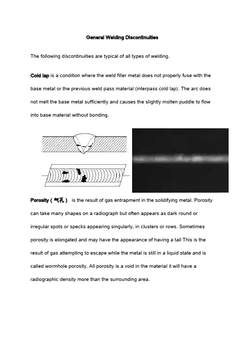
General Welding DiscontinuitiesThe following discontinuities are typical of all types of welding.Cold lap is a condition where the weld filler metal does not properly fuse with the base metal or the previous weld pass material (interpass cold lap). The arc does not melt the base metal sufficiently and causes the slightly molten puddle to flow into base material without bonding.Porosity(气孔)is the result of gas entrapment in the solidifying metal. Porosity can take many shapes on a radiograph but often appears as dark round or irregular spots or specks appearing singularly, in clusters or rows. Sometimes porosity is elongated and may have the appearance of having a tail This is the result of gas attempting to escape while the metal is still in a liquid state and is called wormhole porosity. All porosity is a void in the material it will have a radiographic density more than the surrounding area.Cluster porosity(密集气孔)is caused when flux coated electrodes are contaminated with moisture. The moisture turns into gases when heated and becomes trapped in the weld during the welding process. Cluster porosity appear just like regular porosity in the radiograph but the indications will be grouped close together.Slag inclusions(夹渣)are nonmetallic solid material entrapped in weld metal or between weld and base metal. In a radiograph, dark, jagged asymmetrical shapes within the weld or along the weld joint areas are indicative of slag inclusions.Incomplete penetration (IP) or lack of penetration (LOP)(未焊透)occurs when the weld metal fails to penetrate the joint. It is one of the most objectionable weld discontinuities. Lack of penetration allows a natural stress riser from which a crack may propagate. The appearance on a radiograph is a dark area with well-defined, straight edges that follows the land or root face down the center of the weldment.Incomplete fusion(未融合)is a condition where the weld filler metal does not properly fuse with the base metal. Appearance on radiograph: usually appears as a dark line or lines oriented in the direction of the weld seam along the weld preparation or joining area.Internal concavity or suck back(内凹)is condition where the weld metal has contracted as it cools and has been drawn up into the root of the weld. On a radiograph it looks similar to lack of penetration but the line has irregular edges and it is often quite wide in the center of the weld image.Internal or root undercut(根部咬边)is an erosion of the base metal next to the root of the weld. In the radiographic image it appears as a dark irregular line offset from the centerline of the weldment. Undercutting is not as straight edged as LOP because it does not follow a ground edge.External or crown undercut(外咬边)is an erosion of the base metal next to the crown of the weld. In the radiograph, it appears as a dark irregular line along the outside edge of the weld area.Offset or mismatch(错边)are terms associated with a condition where two pieces being welded together are not properly aligned. The radiographic image is a noticeable difference in density between the two pieces. The difference in density is caused by the difference in material thickness. The dark, straight line is caused by failure of the weld metal to fuse with the land area.Inadequate weld reinforcement(未焊满)is an area of a weld where the thickness of weld metal deposited is less than the thickness of the base material. It is very easy to determine by radiograph if the weld has inadequate reinforcement, because the image density in the area of suspected inadequacy will be more (darker) than the image density of the surrounding base material.Excess weld reinforcement(焊缝余高过高)is an area of a weld that has weld metal added in excess of that specified by engineering drawings and codes. The appearance on a radiograph is a localized, lighter area in the weld. A visual inspection will easily determine if the weld reinforcement is in excess of that specified by the engineering requirements.Cracks(裂纹)can be detected in a radiograph only when they are propagating in a direction that produces a change in thickness that is parallel to the x-ray beam. Cracks will appear as jagged and often very faint irregular lines. Cracks can sometimes appear as "tails" on inclusions or porosity.Discontinuities in TIG weldsThe following discontinuities are peculiar to the TIG welding process. These discontinuities occur in most metals welded by the process including aluminumand stainless steels. The TIG method of welding produces a clean homogeneous weld which when radiographed is easily interpreted.Tungsten inclusions(夹钨). Tungsten is a brittle and inherently dense material used in the electrode in tungsten inert gas welding. If improper welding procedures are used, tungsten may be entrapped in the weld. Radiographically, tungsten is more dense than aluminum or steel; therefore, it shows as a lighter area with a distinct outline on the radiograph.Oxide inclusions are usually visible on the surface of material being welded (especially aluminum). Oxide inclusions are less dense than the surrounding materials and, therefore, appear as dark irregularly shaped discontinuities in the radiograph.Discontinuities in Gas Metal Arc Welds (GMAW)The following discontinuities are most commonly found in GMAW welds. Whiskers are short lengths of weld electrode wire, visible on the top or bottom surface of the weld or contained within the weld. On a radiograph they appear as light, "wire like" indications.Burn-Through(烧穿)results when too much heat causes excessive weld metal to penetrate the weld zone. Often lumps of metal sag through the weld creating a thick globular condition on the back of the weld. These globs of metal are referred to as icicles. On a radiograph, burn through appears as dark spots, which are often surrounded by light globular areas (icicles).Radiograph Interpretation – Castings(铸件)The major objective of radiographic testing of castings is the disclosure of defects that adversely affect the strength of the product. Casting are a product form that often receive radiographic inspection since many of the defects produced by the casting process are volumetric in nature and, thus, relatively easy to detect with this method. These discontinuities of course, are related to casting process deficiencies, which, if properly understood, can lead to accurate accept-reject decisions as well as to suitable corrective measures. Since different types and sizes of defects have different effects of the performance of the casting, it is important that the radiographer is able to identify the type and size of the defects. ASTM E155, Standard for Radiographs of castings has been produced to help the radiographer make a better assessment of the defects found components. The castings used to produce the standard radiographs have been destructively analyzed to confirm the size and type of discontinuities present. The following is a brief description of the most common discontinuity types included in existing reference radiograph documents (in graded types or as single illustrations).RADIOGRAPHIC INDICATIONS FOR CASTINGSGas porosity or blow holes are caused by accumulated gas or air which is trapped by the metal. These discontinuities are usually smooth-walled rounded cavities of a spherical, elongated or flattened shape. If the sprue is not high enough to provide the necessary heat transfer needed to force the gas or air out of the mold, the gas or air will be trapped as the molten metal begins to solidify. Blows can also be caused by sand that is too fine, too wet, or by sand that has a low permeability so that gas can't escape. Too high a moisture content in the sand makes it difficult to carry the excessive volumes of water vapor away from the casting. Another cause of blows can be attributed to using green ladles, rusty ordamp chills and chaplets.Sand inclusions and dross are nonmetallic oxides, appearing on the radiograph as irregular, dark blotches. These come from disintegrated portions of mold or core walls and/or from oxides (formed in the melt) which have not been skimmed off prior to introduction of the metal into the mold gates. Careful control of the melt, proper holding time in the ladle and skimming of the melt during pouring will minimize or obviate this source of trouble.Shrinkage is a form of discontinuity that appears as dark spots on the radiograph. Shrinkage assumes various forms but in all cases it occurs because molten metal shrinks as it solidifies, in all portions of the final casting. Shrinkage is avoided by making sure that the volume of the casting is adequately fed by risers which sacrificially retain the shrinkage. Shrinkage can be recognized in a number of characteristic by varying appearances on radiographs. There are at least four types: (1) cavity; (2) dendritic; (3) filamentary; and (4) sponge types. Some documents designate these types by numbers, without actual names, to avoid possible misunderstanding.Cavity shrinkage appears as areas with distinct jagged boundaries. It may be produced when metal solidifies between two original streams of melt, coming from opposite directions to join a common front; cavity shrinkage usually occurs at a time when the melt has almost reached solidification temperature and there is no source of supplementary liquid to feed possible cavities.Dendritic shrinkage is a distribution of very fine lines or small elongated cavitiesthat may vary in density and are usually unconnected.Filamentary shrinkage usually occurs as a continuous structure of connected linesor branches of variable length, width and density, or occasionally as a network.Sponge shrinkage shows itself as areas of lacy texture with diffuse outlines,generally toward the mid-thickness of heavier casting sections. Sponge shrinkagemay be dendritic or filamentary shrinkage; filamentary sponge shrinkage appearsmore blurred because it is projected through the relatively thick coating between the discontinuities and the film surface.Cracks are thin (straight or jagged) linearly disposed discontinuities that occur after the melt has solidified. They generally appear singly and originate at casting surfaces.Cold shuts generally appear on or near a surface of cast metal as a result of two streams of liquid meeting and failing to unite. They may appear on a radiograph as cracks or seams with smooth or rounded edges.Inclusions are nonmetallic materials in a supposedly solid metallic matrix. They may be less or more dense than the matrix alloy and will appear on the radiograph, respectively, as darker or lighter indications. The latter type is more common in light metal castings.Core shift shows itself as a variation in section thickness, usually on radiographicviews representing diametrically opposite portions of cylindrical casting portions.Hot tears are linearly disposed indications that represent fractures formed in ametal during solidification because of hindered contraction. The latter may occurdue to overly hard (completely unyielding) mold or core walls. The effect of hottears, as a stress concentration, is similar to that of an ordinary crack; how tearsare usually systematic flaws. If flaws are identified as hot tears in larger runs of a casting type, they may call for explicit improvements in technique.Misruns appear on the radiograph as prominent dense areas of variable dimensions with a definite smooth outline. They are mostly random in occurrence and not readily eliminated by specific remedial actions in the process.Mottling is a radiographic indication that appears as an indistinct area of more or less dense images. The condition is a diffraction effect that occurs on relatively vague, thin-section radiographs, most often with austenitic stainless steel. Mottling is caused by interaction of the object's grain boundary material with low-energyX-rays (300 kV or lower). Inexperienced interpreters may incorrectly consider mottling as indications of unacceptable casting flaws. Even experienced interpreters often have to check the condition by re-radiography from slightly different source-film angles. Shifts in mottling are then very pronounced, while true casting discontinuities change only slightly in appearance.Radiographic Indications for Casting Repair WeldsMost common alloy castings require welding either in upgrading from defective conditions or in joining to other system parts. It is mainly for reasons of casting repair that these descriptions of the more common weld defects are provided here. The terms appear as indication types in ASTM E390. For additional information,see the Nondestructive Testing Handbook, Volume 3, Section 9 on the "Radiographic Control of Welds."Slag is nonmetallic solid material entrapped in weld metal or between weld material and base metal. Radiographically, slag may appear in various shapes, from long narrow indications to short wide indications, and in various densities, from gray to very dark.Porosity is a series of rounded gas pockets or voids in the weld metal, and is generally cylindrical or elliptical in shape.Undercut is a groove melted in the base metal at the edge of a weld and left unfilled by weld metal. It represents a stress concentration that often must be corrected, and appears as a dark indication at the toe of a weld.Incomplete penetration, as the name implies, is a lack of weld penetration through the thickness of the joint (or penetration which is less than specified). It is located at the center of a weld and is a wide, linear indication.Incomplete fusion is lack of complete fusion of some portions of the metal in a weld joint with adjacent metal; either base or previously deposited weld metal. On a radiograph, this appears as a long, sharp linear indication, occurring at the centerline of the weld joint or at the fusion line.Melt-through is a convex or concave irregularity (on the surface of backing ring, strip, fused root or adjacent base metal) resulting from complete melting of a localized region but without development of a void or open hole. On a radiograph, melt-through generally appears as a round or elliptical indication.Burn-through is a void or open hole into a backing ring, strip, fused root or adjacent base metal.Arc strike is an indication from a localized heat-affected zone or a change in surface contour of a finished weld or adjacent base metal. Arc strikes are caused by the heat generated when electrical energy passes between surfaces of the finished weld or base metal and the current source.Weld spatter occurs in arc or gas welding as metal particles which are expelled during welding and which do not form part of the actual weld: weld spatter appears as many small, light cylindrical indications on a radiograph.Tungsten inclusion is usually denser than base-metal particles. Tungsten inclusions appear most linear, very light radiographic images; accept/reject decisions for this defect are generally based on the slag criteria.Oxidation is the condition of a surface which is heated during welding, resulting in oxide formation on the surface, due to partial or complete lack of purge of the weld atmosphere. Also called sugaring.Root edge condition shows the penetration of weld metal into the backing ring or into the clearance between backing ring or strip and the base metal. It appears inradiographs as a sharply defined film density transition.Root undercut appears as an intermittent or continuousgroove in the internal surface of the base metal, backingring or strip along the edge of the weld root.Real-time RadiographyReal-time radiography (RTR), or real-time radioscopy, is a nondestructive test (NDT) method whereby an image is produced electronically rather than on film so that very little lag time occurs between the item being exposed to radiation and the resulting image. In most instances, the electronic image that is viewed, results from the radiation passing through the object being inspected and interacting with a screen of material that fluoresces or gives off light when the interaction occurs. The fluorescent elements of the screen form the image much as the grains of silver form the image in film radiography. The image formed is a "positive image" since brighter areas on the image indicate where higher levels of transmitted radiation reached the screen. This image is the opposite of the negative image produced in film radiography. In other words, with RTR, the lighter, brighter areas represent thinner sections or less dense sections of the test object.Real-time radiography is a well-established method of NDT having applications in automotive, aerospace, pressure vessel, electronic, and munition industries, among others. The use of RTR is increasing due to a reduction in the cost of the equipment and resolution of issues such as the protecting and storing digital images. Since RTR is being used increasingly more, these educational materials were developed by the North Central Collaboration for NDT Education (NCCE) to introduce RTR to NDT technician students.Real-time Radiography: An Introductory Course Module for NDT Students Download PDF File。
矿产资源开发利用方案编写内容要求及审查大纲
矿产资源开发利用方案编写内容要求及《矿产资源开发利用方案》审查大纲一、概述
㈠矿区位置、隶属关系和企业性质。
如为改扩建矿山, 应说明矿山现状、
特点及存在的主要问题。
㈡编制依据
(1简述项目前期工作进展情况及与有关方面对项目的意向性协议情况。
(2 列出开发利用方案编制所依据的主要基础性资料的名称。
如经储量管理部门认定的矿区地质勘探报告、选矿试验报告、加工利用试验报告、工程地质初评资料、矿区水文资料和供水资料等。
对改、扩建矿山应有生产实际资料, 如矿山总平面现状图、矿床开拓系统图、采场现状图和主要采选设备清单等。
二、矿产品需求现状和预测
㈠该矿产在国内需求情况和市场供应情况
1、矿产品现状及加工利用趋向。
2、国内近、远期的需求量及主要销向预测。
㈡产品价格分析
1、国内矿产品价格现状。
2、矿产品价格稳定性及变化趋势。
三、矿产资源概况
㈠矿区总体概况
1、矿区总体规划情况。
2、矿区矿产资源概况。
3、该设计与矿区总体开发的关系。
㈡该设计项目的资源概况
1、矿床地质及构造特征。
2、矿床开采技术条件及水文地质条件。
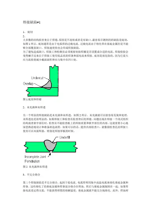
焊接缺陷#11、底切2、大多数的结构损害来自于焊缝,原因是不连续或者是有缺口。
最容易目测到的的缺陷是底切,如图1所示。
底切通常是由于电弧焊的过载电流。
过载电流由于熔化带在基底金属但是不能够全部覆盖缺口。
焊接速度快也会形成焊接缺陷。
为了避免造成缺口,焊接工和检测员必须观察初始焊圈是否设置成合适的电流。
焊接检验会变得棘手还来自于焊接工使用低品质的焊条和弱电流来焊接。
底切是很危险的,因为它放大应力流致使减少截面面积和应力集中在凹口处。
图1.底切和焊瘤2、未充满和未焊透另一个明显的焊接缺陷是未充满和未焊透,如图2所示。
未充满就可以很容易发现和处理。
未焊透也是很明显的,如果焊接工和检查员检查背后的焊缝。
问题出现在焊接一个闭式组织结构或者狭窄部位时,检查员不能检查板上的焊接质量和狭窄部位的内部。
这就需要小心地深思熟虑地设计和准备制造流程。
如果可以的话,提供内部检查口,就像留检查孔给焊接工使其可以双面焊接,特别是焊接厚板的时候。
图2 未充满和未焊透3、不完全熔合第三个焊接缺陷是不完全熔合,起因于低电流。
电弧焊利用集中高温电弧来熔化基底金属和焊条。
这些熔化了的基底金属和焊条混合熔合在焊池,然后与基底金属凝固在一起。
如果焊接电流设定得太低,不能获得理想的熔解温度,基底金属就不能完全地熔化。
此外,焊池材料不充分和在相邻的基底金属之间形成间隙都是不适当的。
这样会留下空洞在焊缝里面或外面,如图3所示。
图3 不完全熔合4、检测缺陷:无损检测大多数的不完全焊透在内部和极细微的,眼睛难以察觉的。
因此,我们需要无损检测来检测焊接质量。
现在有很多种的无损检测,每一种都有各自的优势和局限性。
图4所示的是一位技师在展示磁粉探伤法来检测焊缝。
无损检测是基于鉴定焊缝,无损检测的花费,探测精度,探测深度,等等。
图4 磁粉探伤法5、设计中的焊接缺陷在很多时候,我们应该承认一个事实,焊接缺陷存在于它的结构。
这是需要小心的经过深思熟虑的在设计阶段就应该把缺陷覆盖。
常见的焊接缺陷(内部缺陷):(1)未焊透:母体金属接头处中间(X坡口)或根部(V、U坡口)的钝边未完全熔合在一起而留下的局部未熔合。
未焊透降低了焊接接头的机械强度,在未焊透的缺口和端部会形成应力集中点,在焊接件承受载荷时容易导致开裂。
原因分析造成未焊透的主要原因是:对口间隙过小、坡口角度偏小、钝边厚、焊接线能量小、焊接速度快、焊接操作手法不当。
防治措施⑴对口间隙严格执行标准要求,最好间隙不小于2㎜。
⑵对口坡口角度,按照壁厚和DL/T869-2004《火力发电厂焊接技术规程》的要求,或者按照图纸的设计要求。
一般壁厚小于20㎜的焊口采用V型坡口,单边角度不小于30°,不小于20㎜的焊口采用双V型或U型等综合性坡口。
⑶钝边厚度一般在1㎜左右,如果钝边过厚,采用机械打磨的方式修整,对于单V型坡口,可不留钝边。
⑷根据自己的操作技能,选择合适的线能量、焊接速度和操作手法。
⑸使用短弧焊接,以增加熔透能力。
(2)未熔合:固体金属与填充金属之间(焊道与母材之间),或者填充金属之间(多道焊时的焊道之间或焊层之间)局部未完全熔化结合,或者在点焊(电阻焊)时母材与母材之间未完全熔合在一起,有时也常伴有夹渣存在。
原因分析造成未熔合的主要原因是焊接线能量小,焊接速度快或操作手法不恰当。
防治措施⑴适当加大焊接电流,提高焊接线能量;⑵焊接速度适当,不能过快;⑶熟练操作技能,焊条(枪)角度正确。
(3)气孔:在熔化焊接过程中,焊缝金属内的气体或外界侵入的气体在熔池金属冷却凝固前未来得及逸出而残留在焊缝金属内部或表面形成的空穴或孔隙,视其形态可分为单个气孔、链状气孔、密集气孔(包括蜂窝状气孔)等,特别是在电弧焊中,由于冶金过程进行时间很短,熔池金属很快凝固,冶金过程中产生的气体、液态金属吸收的气体,或者焊条的焊剂受潮而在高温下分解产生气体,甚至是焊接环境中的湿度太大也会在高温下分解出气体等等,这些气体来不及析出时就会形成气孔缺陷。