BF6852AC 自电容多点触控芯片 Datasheet
- 格式:pdf
- 大小:352.14 KB
- 文档页数:21

EducationSPECIFICATION SHEETSpecification Sheet | Page 1 of 2PowerLite ®685W for SMART Board®Interactive WhiteboardsThe ultimate ultra short-throw presentation display for BYOD classrooms.Compatible — specially designed to work with SMART Board M685 and 885 interactive whiteboardsSeamless integration — connect and control your display via the SMART Extended Control Panel (ECP)1Remarkable color accuracy — 3LCD, 3-chip technology delivers high Color Brightness and a wide Color GamutBright display — 3,500 lumens color/white brightness 2 Long-life lamp — lasts up to 10,000 hours in ECO Mode 3Amazing, widescreen images — native WXGA resolution (1280 x 800) and 16:10 formatUltra short-throw presentation display — get an 87" image from 8" away with virtually no shadow interferenceManage your display and send announcements remotely — easy network connectivity; software includedWireless support — display Chromebook,™ iOS ®, Android,™Mac ® and PC screens 4Versatile connectivity — 3x HDMI ® supports multiple high-definition A/V devices, with MHL ® support 5/educationWXGA Resolution1280 x 800Shown with optional wall mount (sold separately)Specification Sheet | Page 2 of 2Epson America, Inc.3840 Kilroy Airport Way, Long Beach, CA 90806Epson Canada Limited185 Renfrew Drive, Markham, Ontario L3R 6G3 www.epson.caVertical: ±3 degrees Horizontal: ±3 degreesMac Connectivity Projector is Mac compatible via USB; DVI to HDMI or VGA adapter (not included); DP to HDMI or VGA adapter (not included)Contrast Ratio Up to 14,000:1Color Reproduction Up to 1.07 billion colorsProjection LensType Digital zoom/Manual focus F-number 1.6Focal Length 3.7 mmZoom Ratio Digital zoom: 1.0 – 1.35OtherDisplay Performance NTSC: 480 linesPAL: 576 lines (Depends on observation of the multi-burst pattern)Input Signal NTSC/NTSC4.43/PAL/M-PAL/N-PAL/PAL60/SECAMSpeaker 16 W (mono)Operating Temperature 41 ˚ to 104 ˚F (5 ˚ to 40 ˚C) Power Supply Voltage 100 – 240 V ±10%, 50/60 Hz Power Consumption 373 W (Normal Mode) 324 W (ECO Mode)2.2 W Standby (Communication On) 0.23 W Standby (Communication Off)Fan Noise35 dB (Normal Mode) 29 dB (ECO Mode)Security Kensington-style lock provision, padlock and security cable hole, Password-protect FunctionExcluding Feet 14.5" x 15.8" x 5.9"Weight 12.6 lbRemote ControlFeatures Source Search, HDMI/Video, LAN, Computer, USB, Power, Aspect, Color Mode, Volume, E-zoom, A/V Mute, Freeze, Menu, Page Up and Down, Home, Auto, Mouse Functions, User, Split Screen 6Operating Distance Front/rear: 19.7 ft (6 m)Eco FeaturesRoHS compliant Recyclable product 7Epson America, Inc. is a SmartWay ® Transport Partner 8SupportEpson Connection SM Pre-sales supportU.S. and Canada: 800-463-7766 Service Programs 2-year projector limited warranty, Epson Road Service program, PrivateLine ® dedicated toll-free support and 90-day limited lamp warrantyremote control, batteries, user manual CD, projector software CDs, Quick Setup Sheet, Installation Guide, template sheet, projector feetOrdering InformationPowerLite 685W for SMART V11H744620Genuine Epson Lamp V13H010L91Air Filter (ELPAF49)V13H134A49 PowerLite Pilot ™ 2 (ELPCB02) V12H614020Active Speakers (ELPSP02)V12H467020Wireless 802.11b/g/n LAN Unit (ELPAP10) V12H731P02Epson DC-21 Document Camera (ELPDC21) V12H758020100" WhiteboardV12H831000Ultra Short-throw Wall Mount (ELPMB46) V12H777020Adapter for SMARTUF55/65/70/75 series mountsV12H870001Specifications and terms are subject to change without notice. EPSON and PowerLite are registered trademarks, EPSON Exceed Your Vision is a registered logomark and Better Products for a Better Future and Epson iProjection are trademarks of Seiko Epson Corporation. PrivateLine is a registered trademark, Pilot is a trademark and Epson Connection is a service mark of Epson America, Inc. Mac is a trademark of Apple Inc., registered in the U.S. and other countries. Android and Chromebook are trademarks of Google Inc. SmartWay is a registered trademark of the U.S. Environmental Protection Agency. All other product and brand names are trademarks and/or registered trademarks of their respective companies. Epson disclaims any and all rights in these marks. Copyright 2019 Epson America, Inc. Com-SS-Oct-13 CPD-52820R1 1/19/educationContact:1 Existing SMART Board M685 and 885 installations require the SMART Cable Adapter Kit, sold separately. |2 Color brightness (color light output) and white brightness (white light output) will vary depending on usage conditions. Color light output measured in accordance with IDMS 15.4; white light output measured in accordance with ISO 21118. |3 Lamp life will vary depending upon mode selected, environmental conditions and usage. Lamp brightness decreases over time. |4 For wireless functionality, including via the Epson iProjection™ App, the projector must be configured on a network, either through the Ethernet port on the projector (check model specifications for availability) or via a wireless connection. Check your owner’s manual to determine if a wireless LAN module must be purchased separately to enable a wireless connection. Not all Epson projectors are able to be networked. The Epson iProjection App does not support all files and formats. See for details. |5 Includes one Mobile High-Definition Link ® (MHL) HDMI port. |6 Consult your user manual for input combinations. |7 For convenient and reasonable recycling options, visit /recycle |8 SmartWay is an innovative partnership of the U.S. Environmental Protection Agency that reduces greenhouse gases and other air pollutants and improves fuel efficiency.Learn more about how our products can empower your institution. Visit us at /foreducation。

D atasheetairMAX® ac CPE with Dedicated Management RadioModel: LBE-5AC-Gen2Lightweight, Low-Cost SolutionFull Adjustment FlexibilityQuick Assembly and InstallationD a t a s h e e tHardware OverviewFull Adjustment FlexibilityThe LiteBeam 5AC features a two-mount system that provides adjustment flexibility along both axes for versatile mounting options. The mounting system, coupled with the built-in bubble level, enables quick and easy alignment.Improved Mounting and Surge Protection Featuring enhanced protection against power surges, the LiteBeam 5AC Gen 2 offers a more robust mount with separate azimuth and elevation adjustments.Antenna FeedFeedReceiverElevation AzimuthMountLiteBeam 5ACBuilt-InU M obileThe LiteBeam 5AC Gen 2 integrates a separate Wi-Fi radio for fastand easy setup using your mobile device.Accessing airOS via Wi-FiThe U M obile App provides instant accessibility to the airOSconfiguration interface and can be downloaded from theApp Store (iOS) or Google Play™ (Android). U M obile allows you toset up, configure, and manage the LiteBeam 5AC Gen 2. It offersthe following options once you're connected or logged in to thedevice:Status Check link status information or the basic configurationsettings of the LiteBeam 5AC Gen 2.Configuration Change or update the existing configuration ofthe LiteBeam 5AC Gen 2.Tools Access tools for initial installation and configuration of theLiteBeam 5AC Gen 2.Actions Back up or update the configuration, upload newfirmware, reboot the device, reset the device to factory defaults,access the airOS UI in the web browser, or disconnect from theLiteBeam 5AC Gen 2.SpecificationsSpecifications are subject to change. Ubiquiti products are sold with a limited warranty described at: /support/warranty©2017 Ubiquiti Networks, Inc. All rights reserved. Ubiquiti, Ubiquiti Networks, the Ubiquiti U logo, the Ubiquiti beam logo, airMAX, airOS, airMagic, InnerFeed, and LiteBeam are trademarks or registered trademarks of Ubiquiti Networks, Inc. in the United States and in other countries. All other trademarks are the property of their respective owners.Vertical Azimuth Vertical ElevationHorizontal AzimuthHorizontal ElevationReturn Loss。

FM17522E通用非接触读写器芯片技术手册2017.10本资料是为了让用户根据用途选择合适的上海复旦微电子集团股份有限公司(以下简称复旦微电子)的产品而提供的参考资料,不转让属于复旦微电子或者第三者所有的知识产权以及其他权利的许可。
在使用本资料所记载的信息最终做出有关信息和产品是否适用的判断前,请您务必将所有信息作为一个整体系统来进行评价。
采购方对于选择与使用本文描述的复旦微电子的产品和服务全权负责,复旦微电子不承担采购方选择与使用本文描述的产品和服务的责任。
除非以书面形式明确地认可,复旦微电子的产品不推荐、不授权、不担保用于包括军事、航空、航天、救生及生命维持系统在内的,由于失效或故障可能导致人身伤亡、严重的财产或环境损失的产品或系统中。
未经复旦微电子的许可,不得翻印或者复制全部或部分本资料的内容。
今后日常的产品更新会在适当的时候发布,恕不另行通知。
在购买本资料所记载的产品时,请预先向复旦微电子在当地的销售办事处确认最新信息,并请您通过各种方式关注复旦微电子公布的信息,包括复旦微电子的网站(/)。
如果您需要了解有关本资料所记载的信息或产品的详情,请与上海复旦微电子集团股份有限公司在当地的销售办事处联系。
商标上海复旦微电子集团股份有限公司的公司名称、徽标以及“复旦”徽标均为上海复旦微电子集团股份有限公司及其分公司在中国的商标或注册商标。
上海复旦微电子集团股份有限公司在中国发布,版权所有。
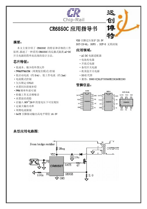
目录目录 (3)表目录 (6)图目录 (10)1产品综述 (11)1.1产品简介 (11)1.2产品特点 (11)1.3结构框图 (12)1.4封装引脚 (13)1.4.1FM17522E封装引脚 (13)2功能描述 (15)2.1总体描述 (15)2.2ISO/IEC14443A功能支持 (15)3FM17522E寄存器 (17)3.1FM17522E寄存器概述 (17)3.1.1寄存器总表 (17)3.1.2寄存器位行为 (18)3.2寄存器描述 (19)3.2.1Page 0:命令和状态 (19)3.2.2Page 1:通讯 (26)3.2.3Page 2:配置 (33)3.2.4Page 3:测试 (38)3.2.5扩展寄存器 (43)4HOST接口 (45)4.1H OST接口自动侦测 (45)4.2SPI接口 (45)4.2.1SPI读数据 (45)4.2.2SPI写数据 (45)4.2.3SPI地址字节 (46)4.3UART接口 (46)4.3.1UART传输速率可配 (46)4.3.2UART帧格式 (47)4.4I2C总线接口 (48)4.4.1数据有效性 (49)4.4.2START和STOP状态 (49)4.4.3字节格式 (49)4.4.4Acknowledge (49)4.4.57位地址 (50)4.4.6寄存器写入访问 (51)4.4.7寄存器读取访问 (51)4.4.8高速模式 (52)4.4.9高速传输 (52)4.4.10HS模式下的数据传输格式 (52)4.4.11F/S模式与HS模式间转换 (53)4.4.12低速模式 (53)4.5扩展寄存器的访问 (53)5模拟电路接口和非接触接口控制 (55)5.1概述 (55)5.2发射驱动 (55)5.3串行数据切换开关 (56)6CRC协处理器 (57)7FIFO缓冲 (58)7.1FIFO缓冲器的访问 (58)7.2FIFO缓冲器的控制 (58)7.3FIFO缓冲器的状态信息 (58)8中断请求系统 (59)8.1中断源概述 (59)9TIMER计时单元 (60)10低功耗模式 (61)10.1D EEP P OWER D OWN (61)10.2H ARD P OWER D OWN (61)10.2.1HPD下数据保存功能 (61)10.3S OFT P OWER D OWN (62)10.4射频关闭模式 (62)11低电压检测功能 (63)12振荡器电路 (64)13复位和晶振起振时序 (65)13.1复位信号要求 (65)13.2晶振起振时序 (65)14指令集 (66)14.1概述 (66)14.2指令的一般行为 (66)14.3FM17522E指令描述 (66)14.3.1IDLE (66)14.3.2Mem (66)14.3.3Generate RandomID (66)14.3.4CalcCRC (67)14.3.5Transmit (67)14.3.6NoCmdChange (67)14.3.7Receive (67)14.3.8Transceive (67)14.3.9Authent (67)14.3.10SoftReset (68)15测试信号 (69)15.1测试总线 (69)15.2引脚AUX1/AUX2上的测试信号 (70)15.3PRBS (70)16典型应用图 (71)17电气参数 (72)17.1极限额定参数 (72)17.2.2I2C交流参数 (73)18订货信息 (75)19封装信息 (76)19.1QFN32封装尺寸图 (76)版本信息 (77)上海复旦微电子集团股份有限公司销售及服务网点 (78)表目录表1-1FM17522E QFN32封装引脚说明 (14)表2-1FM17522E ISO/IEC A通讯简述 (15)表3-1寄存器总表 (18)表3-2扩展寄存器总表 (18)表3-3寄存器位行为及其描述 (18)表3-4RFU寄存器 (19)表3-5RFUR EG位描述 (19)表3-6C OMMAND R EG寄存器 (19)表3-7C OMMAND R EG位描述 (19)表3-8C OMM IE N R EG寄存器 (19)表3-9C OMM IE N R EG位描述 (20)表3-10D IV IE N R EG寄存器 (20)表3-11D IV IE N R EG位描述 (20)表3-12C OMM IR Q R EG寄存器 (20)表3-13C OMM IR Q R EG位描述 (21)表3-14D IV IR Q R EG寄存器 (21)表3-15D IV IR Q R EG位描述 (21)表3-16E RROR R EG寄存器 (21)表3-17E RROR R EG位描述 (22)表3-18S TATUS1R EG寄存器 (22)表3-19S TATUS1R EG位描述 (22)表3-20S TATUS2R EG寄存器 (22)表3-21S TATUS2R EG位描述 (23)表3-22FIFOD ATA R EG寄存器 (23)表3-23FIFOD ATA R EG寄存器位描述 (23)表3-24FIFOL EVEL R EG寄存器 (23)表3-25FIFOL EVEL R EG寄存器 (24)表3-26W ATER L EVEL R EG寄存器 (24)表3-27W ATER L EVEL R EG寄存器位描述 (24)表3-28C ONTROL R EG寄存器 (24)表3-29C ONTROL R EG寄存器位描述 (24)表3-30B IT F RAMING R EG寄存器 (25)表3-31B IT F RAMING R EG寄存器位描述 (25)表3-32C OLL R EG寄存器 (25)表3-33C OLL R EG寄存器位描述 (25)表3-34EXR EG寄存器 (26)表3-35EXR EG寄存器位描述 (26)表3-36RFU寄存器 (26)表3-37RFUR EG位描述 (26)表3-38M ODE R EG寄存器 (26)表3-39M ODE R EG位描述 (27)表3-40T X M ODE R EG寄存器 (27)表3-41T X M ODE R EG位描述 (27)表3-42R X M ODE R EG寄存器 (27)表3-43R X M ODE R EG位描述 (28)表3-44T X C ONTROL R EG寄存器 (28)表3-45T X C ONTROL R EG位描述 (28)表3-46T X ASKR EG寄存器 (29)表3-47T X ASKR EG位描述 (29)表3-48T X S EL R EG寄存器 (29)表3-52R X T HRESHOLD R EG寄存器 (30)表3-53R X T HRESHOLD R EG寄存器位描述 (30)表3-54D EMOD R EG寄存器 (30)表3-55D EMOD R EG位描述 (31)表3-56RFU寄存器 (31)表3-57RFUR EG位描述 (31)表3-58RFU寄存器 (31)表3-59RFUR EG位描述 (31)表3-60T X R EG寄存器 (31)表3-61T X R EG位描述 (32)表3-62R X R EG寄存器 (32)表3-63R X R EG位描述 (32)表3-64RFU寄存器 (32)表3-65RFUR EG位描述 (32)表3-66S ERIAL S PEED R EG寄存器 (32)表3-67S ERIAL S PEED R EG位描述 (32)表3-68RFU寄存器 (33)表3-69RFUR EG位描述 (33)表3-70CRCR ESULT R EG寄存器 (33)表3-71CRCR ESULT R EG位描述 (33)表3-72CRCR ESULT R EG寄存器 (33)表3-73CRCR ESULT R EG位描述 (33)表3-74RFU寄存器 (33)表3-75RFUR EG位描述 (34)表3-76M OD W IDTH R EG寄存器 (34)表3-77M OD W IDTH R EG位描述 (34)表3-78RFU寄存器 (34)表3-79RFUR EG位描述 (34)表3-80RFC FG R EG寄存器 (34)表3-81RFC FG R EG位描述 (35)表3-82G S NR EG寄存器 (35)表3-83G S NR EG位描述 (35)表3-84CWG S PR EG寄存器 (35)表3-85CWG S PR EG位描述 (35)表3-86M OD G S PR EG寄存器 (35)表3-87M OD G S PR EG位描述 (36)表3-88TM ODE R EG寄存器 (36)表3-89TM ODE R EG位描述 (36)表3-90TP RESCALER R EG寄存器 (37)表3-91TP RESCALER R EG位描述 (37)表3-92TR ELOAD H I R EG寄存器 (37)表3-93TR ELOAD H I R EG位描述 (37)表3-94TR ELOAD L O R EG寄存器 (37)表3-95TR ELOAD L O R EG位描述 (37)表3-96TC OUNTER V AL H I R EG寄存器 (37)表3-97TC OUNTER V AL H I R EG位描述 (38)表3-98TC OUNTER V AL L O R EG寄存器 (38)表3-99TC OUNTER V AL L O R EG位描述 (38)表3-100RFU寄存器 (38)表3-101RFUR EG位描述 (38)表3-102T EST S EL1R EG寄存器 (38)表3-103T EST S EL1R EG位描述 (38)表3-107T EST P IN E N R EG位描述 (39)表3-108T EST P IN V ALUE R EG寄存器 (39)表3-109T EST P IN V ALUE R EG位描述 (40)表3-110T EST B US R EG寄存器 (40)表3-111T EST B US R EG位描述 (40)表3-112T EST C TRL R EG寄存器 (40)表3-113T EST C TRL R EG位描述 (40)表3-114V ERSION R EG寄存器 (40)表3-115V ERSION R EG位描述 (41)表3-116A NOLOG T EST R EG寄存器 (41)表3-117A NOLOG T EST R EG位描述 (41)表3-118T EST DAC1R EG寄存器 (41)表3-119T EST DAC1R EG位描述 (42)表3-120T EST DAC2R EG寄存器 (42)表3-121T EST DAC2R EG位描述 (42)表3-122T EST ADCR EG寄存器 (42)表3-123T EST ADCR EG位描述 (42)表3-124RFTR EG寄存器 (42)表3-125RFTR EG位描述 (43)表3-126RFTR EG寄存器 (43)表3-127RFTR EG位描述 (43)表3-128RFTR EG寄存器 (43)表3-129RFTR EG位描述 (43)表3-130RFTR EG寄存器 (43)表3-131RFTR EG位描述 (43)表3-132H PD C TRL寄存器 (43)表3-133H PD C TRL位描述 (44)表3-134U SE R ET寄存器 (44)表3-135U SE R ET位描述 (44)表3-136LVD CTRL寄存器 (44)表3-137LVD CTRL位描述 (44)表4-1不同接口类型的连接标准 (45)表4-2MOSI和MISO的字节顺序 (45)表4-3MOSI和MISO字节顺序 (45)表4-4地址字节格式 (46)表4-5BR_T0和BR_T1设置 (46)表4-6UART传输波特率选择 (46)表4-7UART帧格式 (47)表4-8UART读数据字节顺序 (47)表4-9写入数据字节顺序 (47)表4-10地址字节 (48)表4-11I2C地址对应引脚 (51)表4-12扩展寄存器字节定义 (53)表5-1TX1引脚相关控制信号和设置 (55)表5-2TX2引脚相关控制信号和设置 (56)表6-1CRC协处理器参 (57)表8-1中断源 (59)表10-1HPD模式保持寄存器列表 (62)表14-1指令概述 (66)表15-1测试信号路径选择(T EST S EL2R EG =07H) (69)表15-2测试信号描述 (69)表15-3测试信号路径选择(T EST S EL2R EG =0D H) (69)表15-5测试信号路径选择(T EST S EL2R EG =19H) (69)表15-6测试信号描述 (69)表15-7测试信号描述 (70)表17-1FM17522E极限额定参数 (72)表17-2FM17522E推荐工作条件 (72)表17-3SPI交流参数 (73)表17-4I2C交流参数 (74)图目录图1-1FM17522E结构框图 (12)图1-2FM17522E QFN32封装引脚图(TOP VIEW) (13)图2-1FM17522E应用框图 (15)图2-2PCD标准帧格式 (15)图2-3PICC标准帧格式 (16)图4-1UART读取数据时序图 (47)图4-2UART写入数据时序图 (48)图4-3I2C总线接口 (48)图4-4I2C总线上的位传输 (49)图4-5START和STOP状态 (49)图4-6I2C总线上的ACKNOWLEDGE信号 (50)图4-7I2C总线上的数据传输 (50)图4-8START过程后的第一位字节 (50)图4-9寄存器读/写访问 (51)图4-10I2C总线HS模式协议转换 (52)图4-11I2C总线HS模式协议帧格式 (53)图4-12写扩展寄存器操作流程 (54)图4-13读扩展寄存器操作流程 (54)图5-1TX1和TX2间串行数据转换 (56)图12-1石英晶体连接 (64)图13-1振荡器启动时间 (65)图16-1典型应用图 (71)图17-1SPI时序图 (73)图17-2快速和标准模式下的I2C总线时序图 (74)图19-1FM17522E QFN32封装尺寸图 (76)1 产品综述1.1 产品简介FM17522E是一款高度集成的工作在13.56MHz下的非接触读写器芯片,支持符合ISO/IEC 14443TypeA协议的非接触读写器模式。

6832芯片参数6832芯片有两种,一种是FU6832,另一种是SD6832。
FU6832是一款双核芯片,包括8051内核和ME。
其指令周期大多为1T或2T,拥有16kB的Flash ROM,带CRC校验功能,支持程序自烧录和代码保护功能。
它还配备了256 bytes的IRAM和768 bytes的XRAM。
ME部分支持比例积分/微分器(PI/PID)、BLDC模块、FOC模块、MDU等计算功能。
此外,它还具有单周期1616位乘法器、16周期32 / 16位除法器、4级优先级中断、15个中断源等功能。
在GPIO方面,FU6832L有35个GPIO。
定时器方面,它有2个通用带抓捕功能可编程定时器、1个支持QEP解码编程定时器、1个BLDC电机专用定时器、1个通用定时器以及1个RTC定时器。
在通讯接口上,它有1个SPI、1个I2C、2个UART接口,其中UART2支持LIN Slave模式和Pin功能转移。
另外,它还有2通道DMA,支持用于I2C/SPI/UART数据传输。
在模拟外设方面,它有12位ADC,1uS转换时间,可选择内部VREF、外部VREF作参考电压。
ADC通道数为FU6832L的14通道,内置VREF参考,可配置3V、4V、、VDD5,内置VHALF(1/2 VREF)参考输出。
此外,它还有3个独立运算放大器,其中AMP0可配置为自动增益放大器。
SD6832是一款用于开关电源的内置高压MOSFET外置采样电阻的电流模式PWM+PFM控制器IC芯片。
其工作频率为25kHz\~67kHz,采用8脚双列直插式(8DIP)封装工艺。
请注意,不同型号的6832芯片可能具有不同的参数和特性。
如需了解更多信息,建议查阅芯片规格书或咨询芯片厂商。
599 Menlo Drive, Suite 100Rocklin, California 95765, USAOffice: (916) 624-8333Fax: (916) 624-8003General: info@Technical: support@Web Site: Educational: Gripper Kit for the Boe-Bot® Robot (#28202)The Gripper KitThis kit allows your Parallax Boe-Bot® Robot to pick up objects. TheBoe-Bot robot (#28132 serial or #28832 USB) is sold separately.Before getting started, take an inventory of the parts in your kit. UseFig #1 to identify each part to the parts list. Once you haveinventoried your kit, proceed to Step #1.11423456791011121315161783Recommended Tools•Small needle nosed pliers•Phillips #2 point screwdriver•Small flat-blade screwdriver• A sharp-tipped hobby knife,such as an X-Acto® knife-OR-A hand drill with 5/64″ bitWARNING!DO NOT use electricscrewdrivers with this kit. Pleaseassemble using hand tools onlyto avoid damaging your Gripper.Step #1: SpacersItem Qty Description 4 (2) Gripper link 5 (2) #4 x 1" spacer• Insert spacers into plastic Gripper links. • Use Fig #2 as a guide to install the spacers. Whendone, the pieces will appear as shown in Fig #3.Fig #2Fig #3Step #2: Gripper LinksItem Qty Description6 (1) Gripper plate7 (2) 4-40 x 1.25" pan head screw8 (2) 4-40 Hex Nut•Be sure the angled portions on top of the plastic links match the angles on top of the Gripper as shown in Fig #5.• Move links and spacers into the Gripper plate, thensecure with 4-40 screws and nuts as shown in Fig #4. • Tighten securely.• Before continuing, double check your work to ensurethat the pieces are angled as in Fig #5.Fig #4 Fig #5Step #3: Foam TapeItem Qty Description14 (4) foam tape• Cut four pieces of foam tape, each 2 inches long. •Apply foam tape to the Gripper plate as shown in Fig #7.This completes the left-side Gripper sub-assembly.Fig #6Fig #7Step #4: Second Gripper Sub-assemblyItem Qty Description4 (2) Gripper link5 (2) #4 x 1" spacer6 (1) Gripper plate7 (2) 4-40 x 1.25" pan head screw8 (2) 4-40 hex nut 14 (4) foam tape• Repeat Steps #1 through #3 to build the right-sideGripper sub-assembly in a similar fashion.• Be sure the angled portions of the links match with theGrippers face to face. Position the pieces exactly as they appear in Fig #8.• Double check your work, then proceed to Step #5.Fig #8•Assemble the Gripper sub-assemblies to the upperand lower linkage plates as shown in Fig #9. In turn, insert each plastic link, a spacer, and secure with 4-40 screws and nuts.• When all four plastic links are installed, tighten securely.•Double check your work against Fig #10. Note that the hinge tabs on the bottom plate face up, while hinge tabs on top plate face down.Step #5: Linkage PlatesItem Qty Description3 (2) linkage plate 5 (4)#4 x 1" spacer 7(4) 4-40 x 1.25" pan head screw 8 (4) 4-40 hex nutStep #6: Control ArmsItem Qty Description 10 (2) control arm 15 (4) 4-40 x ¼" pan head screw• Attach control arms with 4-40 x ¼" screws as shown in Fig #11.•Final assembly must match Fig #12. Double check your work, then proceed to Step #7.Fig #11Fig #12Step #7: E-Z ConnectorsItem Qty Description 13 (2) Brass 0.072 E-Z Connector• Follow the directions on the package to install the E/Z Connector into the control arms. Use the nylon washers, but set the screws aside for now.• Check your work; your final assembly should match Fig #13.Fig #13Step #8: Install Gripper Hinge PlateItem Qty Description1 (1) hinge mount 15 (3) 4-40 x ¼" pan head screw 8 (3) 4-40 hex nutNote: It is recommended that the servos and tires on the Boe-Bot be installed with the wheels biased toward the front of the unit as shown below. This will prevent the Boe-Bot from tipping when it picks up objects.• Attach hinge mount to the Boe-Bot with the 4-40 x ¼" screws and nuts as shown in Fig #14 and Fig #15. • Double check your work against Fig #16.Fig #14 Top ViewFig #15 Bottom ViewFig #16Assembled ViewStep #9: Position Gripper on Boe-BotItem Qty Description(1) Gripper assembly (1) Boe-Bot robot• Remove one wheel to allow for dowel pin installation in the next step, Step #10.• Position the Gripper assembly onto the hinge mount as shown in Fig #17 below.•Place the top hinge tabs over the tabs on the hinge mount so the top of the Gripper stays on the hinge mount.Fig #17Step #10: Insert Dowel Pin Item Qty Description2 (1) dowelpin• Insert dowel pin.•If dowel pin slips in very easily, use needle nose pliers to slightly crimp the center of the hinge plate.• Replace wheel.Fig #18Fig #19Fig #21Step #12: Servo BracketsItem Qty Description16 (2) servo brackets 17 (4) 4-40 x 3/8" pan head screw 8 (4) 4-40 hex nut 11 (1) Parallax Standard Serv o• Attach servo brackets to servo with 4-40 screws and nuts. Make sure the metal brackets are placed below the plastic servo tabs as shown in Fig #22.•The final assembly should match Fig #23. Double check your work, then proceed to Step #13.Note: Only one arm of the servo horn is shown for clarity.Fig #22Fig #23Step #13: Bend Actuator RodItem Qty Description 12 (1) actuator rod•Using the needle nose pliers, bend actuator rod at mid-point. Then bend as shown in Fig #24.Fig #24Step #14: Install Actuator Rod Item Qty Description12 (1) actuatorrod11 (1) Parallax Standard Servo•Thread bent rod through servo horn as shown in Fig #25.Fig #25分销商库存信息: PARALLAX 28202。
双通道电容式触摸键控制芯片XC2862目录1概述 (3)1.1 特性 (3)1.2 系统框图 (4)2管脚定义 (5)3功能描述 (6)4电气特性 (7)5关键特性 (8)5.1 环境自适应能力 (8)5.1.1环境漂移跟随 (8)5.1.2环境突变校准 (8)5.2 接近检测 (8)6用户设置 (9)灵敏度设置 (9)7应用指南 (10)7.1 触摸键 (10)7.2 接近检测 (11)8PCB设计 (12)8.1 触摸键设计 (12)8.1.1触摸键 (12)8.1.2触摸键的常用结构 (12)8.1.3触摸键设计 (13)8.2 PCB布线 (13)9封装 (14)1概述XC2862是一款支持宽工作电压范围的双输入双输出电容式触摸键控制芯片。
XC2862内部集成高分辨率触摸检测模块和专用信号处理电路,以保证芯片对环境变化具有灵敏的自动识别和跟踪功能,且内置特殊算法以实现防水、抗干扰等需求。
该芯片可满足用户在复杂应用中对稳定性、灵敏度、功耗、响应速度、防水、带水操作、抗震动、抗电磁干扰等方面的高体验要求。
XC2862为方便用户在应用中可对触摸键的灵敏度进行自主控制,特设置了灵敏度控制位。
用户只需在PCB设计中对这个管脚的逻辑电平值进行设置,就能自由选择在具体应用中芯片体现出的检测灵敏度。
XC2862还内置了上电复位及电源保护电路,在典型应用中可无需任何外部器件,也无需软件、程序或参数烧录。
芯片应用的开发过程非常简单,最大限度的降低了方案成本。
XC2862可广泛适用于遥控器、灯具调光、各类开关以及小家电和家用电器控制界面等应用中。
1.1特性工作电压:2.5V~5.5V两个高灵敏度的触摸检测通道无需进行参数烧录2级灵敏度可调(通过设置一位管脚的逻辑电平实现)响应速度快抗电磁干扰能力强防水及带水操作功能接近检测功能独特的环境跟踪和自适应能力低功耗(典型工作电流< 25uA)内置上电复位(POR)和电源保护电路CMOS电平输出1.2系统框图XC2862包含PMU和Touch Key Core两个部分,其系统框图如图1所示。
BF6852A/C 自电容多点触控芯片Datasheet1概述1.1 特点●自电容感应技术●最多支持28个检测通道●支持单点触摸和两点手势●最大可以支持5.3寸屏●低功耗模式——睡眠模式和等待模式●标准的IIC接口——IIC从机模式:支持100Kbps和400Kbps●电源电压范围:2.7~3.6V●IO电压范围:1.65~3.6V●环境自适应●具有防水功能●支持单层三角形屏●FPS:高达100Hz,反应时间<10ms●工作模式——中断模式&& 查询模式●ESD HBM:±4KV●工作温度:-40°C ~ +85°C●封装形式:QFN401.2 典型应用●手机●手持/移动终端2简介BF6852A/C是一款内置MCU的自电容触摸控制IC,其采用了自电容检测技术,支持全ITO单层三角形屏的应用方案;支持真实单点触摸和两点手势,最大可支持5.3寸屏。
该触控IC包含了一个MCU和一些其他的外围设备,通过检测及运算识别有效的触摸信息,然后把手指的触摸位置转换成坐标,通过IIC接口把信息传送给上位机。
3 IC 描述3.1 BF6852A/C 封装SN3SN4SN5SN6SN7SN8SN11SN12SN13SN14S N 15S N 16S N 17S N 18S N 19S N 21S N 22S N 23S N 24S N 25SN26SN27SN29SN30SN31SN32SN33SN34NCV S SS D AS C KD A VV D 2I O V C CV C CV DC O U T C O U T 2图1 BF6852A/C QFN40 5mm ×5mm 封装3.2 BF6852A/C pin脚描述4传感器设计请参考《三角形触摸屏设计规则及量产注意事项》。
5 IIC 通信BF6852A/C 提供标准的IIC 通信接口,由SCL 和SDA 与主机进行通信,在系统中BF6852A/C 始终作为从机设备,所有通信都是由主机发起,通信速度有400Kbps 和100Kbps ,二者可选。
BF6852A/C 芯片对触控屏检测通道上的电容值进行采样,通过比较电容值的变化值来判断触摸状态,并通过算法实现触摸点的定位。
5.1 IIC 总线时序图SCLSDA图2 IIC 总线时序图IIC 时序参数如下表所示:5.2 IIC读写流程5.2.1 IIC写流程主机可以根据寄存器列表对相关寄存器进行写操作,时序图如下图所示:S:启动信号Device address_W:带写控制位的从设备地址Register_Address:待写入的8位寄存器地址A:应答信号Data_1~Data_n:数据字节1~nP:停止信号5.2.2 IIC读流程主机可以根据寄存器列表对相关寄存器进行读操作,时序图如下图所示:S:启动信号Device address_W:带写控制位的从设备地址Device address_R:带读控制位的从设备地址Register_Address:待读取的8位寄存器地址A:应答信号Data_1~Data_n:数据字节1~nP:停止信号5.3寄存器列表及说明5.3.1 寄存器列表5.3.2 寄存器说明1、D_SN0~D_SN5●程序版本号读取:主机需连续读取字节,操作如下START->(设备地址+写)->寄存器地址0x00->RESTART->(设备地址+读)->连续读取版本号6个byte ->STOP2、Operation mode:配置该寄存器可实现以下功能●休眠模式:当对寄存器(0x07)写入0x00时TP进入休眠模式,芯片将停止工作,以降低功耗。
START->(设备地址+写)->寄存器地址0x07->0x00->STOP●唤醒:对寄存器(0x07)写入0x01,将TP唤醒。
START->(设备地址+写)->寄存器地址0x07->0x01->STOP●使能缩放手势:对TP的寄存器(0x07)写入0x11使能缩放功能,而写入0x10则关闭缩放功能。
START->(设备地址+写)->寄存器地址0x07->0x11->STOP3、RESOX_H~RESOX_L、RESOY_H~RESOY_L:X,Y坐标分辨率●主机读取操作如下:START->(设备地址+写)->寄存器地址0x08->RESTART->(设备地址+读)-> 连续读4个byte->STOP4、TOUCH:包含触摸按键和手指触摸个数的信息,高4位为1000b,代表发送手指触摸个数信息;高4位为1001b,代表发送按键信息,如表2所示:5、X1_H~X2_H、X1_L~X2_L、Y1_H~Y2_H、Y1_L~Y2_L坐标X,Y的高低8位,其中包含了触摸ID号和触摸状态的信息。
●Touch state:包含三种手指触摸状态,第一次触摸,保持触摸,抬起。
如表3所示:●Touch ID按如下规则定义:●最先按下的触摸点ID为1,后依次增加,最大到2。
当有触摸点抬起时,不影响其他触摸点ID。
同一个触摸点的数据并不是固定在同一个寄存器中,靠后的触摸点在其他触摸点抬起时,在寄存器中的位置会往前移动。
例如:当有2个手指触摸时,第一个手指触摸点ID为1,数据放在0x5d~0x60寄存器中,第二个手指触摸点ID为2,数据放在0x61~0x64寄存器中。
当第一个手指抬起后,第二个手指仍然触摸,此时第二个手指触摸点ID依然是2,触摸点数T ouchnum仍为2,寄存器0x5d~0x60仍保留第一个手指的ID号为1,Touchstate为抬起,主机读完这帧数据后下一帧数据的触摸点数即变成1,第二个手指触摸数据位置相应往前移动到0x5d~0x60寄存器中,原先存放位置0x61~0x64寄存器清零。
这时如果再有一个手指触摸,数据放置在0x61~0x64寄存器中。
●触摸坐标数据格式如表4所示:无触摸Data1为0x80,单点触摸为0x81,两点触摸为0x82;Data1为0x80时,Data2~Data9都为0。
根据手指触摸个数可以决定后面读取坐标的长度。
●触摸按键数据格式如表5所示:按键触摸后抬起为0x90。
●主机读取坐标信息,操作如下:START->(设备地址+写)->寄存器地址0x5c->RESTART->(设备地址+读)-> 连续读坐标信息->STOP●主机读取按键信息,操作如下:START->(设备地址+写)->寄存器地址0x5c->RESTART->(设备地址+读)-> 连续读5个byte->STOP 6、手势缩放手势判断功能底层默认屏蔽,如需要此功能请联系FAE工程师,否则主机写命令也无效。
当主机向0x07寄存器中写入0x11指令时,启动手势缩放判断功能,此时从寄存器地址0x5c开始存放缩放手势的信息,数据格式是6个字节,如表6所示:Ges表示放大或缩小的手势,Ges = 0xff表示缩小,Ges=0x01表示放大。
●主机需连续读取手势数据,操作如下:START->(设备地址+写)->寄存器地址0x5c->RESTART->(设备地址+读)-> 连续读取手势信息(6个字节)->STOP放大缩小手势如图3、4所示:图3 放大图4 缩小主机读坐标、按键、手势信息可以都为9个字节,对按键判断就解析前5个字节,对手势判断就解析前6个字节。
5.4 注意事项1、BF6852坐标默认分辨率为2048*2048。
2、BF6852上电初始化需要200ms,由休眠唤醒到稳定工作需要20ms,建议主机操作过程中请预留足够的时间。
3、上电时主机可根据需要读取版本号,读数据操作都是连续读取,请按所标明的主机操作方式读取。
4、上升沿或下降沿触发方式建议主机检测到DAV信号时能立即读取数据,如果延时太长,BF6852已经更新坐标信息,就会造成主机读到的数据有误或丢失数据。
5、当主机进入图片、浏览器等需要使用放大缩小手势功能的界面,建议主机立即发送放大缩小使能命令,退出后也应立即发送关闭使能命令。
6工作模式● 在正常工作状态下,坐标刷新的周期大约是12ms (此时间和配置有关)。
● 在正常工作模式下可通过IIC 发送指令进入SLEEP 模式。
● BF6852A/C可通过IIC 中断唤醒SLEEP ,进入到正常工作模式。
其中,中断发出后需等待2ms 才能进行正常通信。
以从机地址0x58,0x59为例,主机具体操作见下图5。
Sleep 模式Normal 模式图5 IIC 中断唤醒SLEEP 图7应用电路图7.1 应用说明1:若上位机提供IOVCC电源端口或者IOVCC = VCC,请用BF6852A产品型号;2:若上位机不提供IOVCC电源,并且IOVCC = 1.8V,请用BF6852C产品型号。
7.2双电源应用方案(此种方案用BF6852A)7.3 单电源并且IOVCC = VCC应用方案(此种方案用BF6852A)7.4 单电源并且IOVCC = 1.8V应用方案(此种方案用BF6852C)备注:此方案只用在当上位机不提供IOVCC电源并且IOVCC=1.8V时,另外无IIC的上拉电阻。
8 电气特性8.1 DC特性下表列出了我们的产品能保证的电压以及温度的最大值到最小值的范围:2.7V~3.6V,-40℃~85℃,典型值在25℃,2.8V的条件下。
8.2 极限电气参数注:1、焊接温度最高不能超过260℃,在255℃~260℃之间不能超过30s。
2、在应用过程中,如果超出了极限参数的最大值,可能会导致芯片损坏,继而不能正常工作。
9产品封装图6 QFN-40封装(5mm*5mm*0.8mm)BF6852A/C DataSheetDatasheetPage 21 of 21 BYD Microelectronics Co., Ltd.免责声明。