《物理双语教学课件》Chapter 18 Capacitance 电容
- 格式:doc
- 大小:261.00 KB
- 文档页数:11

高中物理课件电容器的电容介绍电容器是物理学中的一个重要概念,它在高中物理课程中占据着重要地位。
本文将介绍电容器的基本概念、电容的计算方法以及电容器的一些应用。
电容器的基本概念电容器是一种用来存储电荷的装置。
它由两个导体板组成,中间由绝缘体(也称为电容介质)隔开。
当电容器上加有电压时,电荷会在导体板之间积聚,形成电场。
电容器的电容即为存储的电荷量和加在电容器上的电压之比。
电容的计算方法电容的计算可以通过以下公式得到:C = Q / V其中,C代表电容,单位为法拉(F),Q代表存储的电荷量,单位为库仑(C),V代表加在电容器上的电压,单位为伏特(V)。
在实际问题中,可以通过给定的条件来计算电容。
例如,当电容器上的电压为5伏特,电荷量为10库仑时,电容为:C = 10C / 5V = 2F电容器的应用电容器在电路中有广泛的应用,下面将介绍几个常见的应用场景。
1. 能量存储电容器可以存储电荷和能量,因此在电子设备中常被用来作为能量存储器。
例如,计算机主板上的电容器可以存储电能,为计算机提供稳定的电源。
2. 信号滤波电容器可以对信号进行滤波,去除高频噪声。
在放大器电路中,可以通过电容器来消除干扰信号,使得输出信号更加纯净。
3. 时间延迟电容器可以在电路中引入时间延迟。
通过调整电容的大小,可以使得电路的响应时间延长或缩短,从而实现不同的功能。
电容器作为一种重要的电路元件,在高中物理课程中有着重要的地位。
本文介绍了电容器的基本概念,电容的计算方法以及电容器在电路中的应用。
了解和掌握这些概念对于深入理解电路原理和解决实际问题具有重要意义。
希望通过本文的介绍,读者能够对电容器的电容有更清晰的理解,并在日常生活和学习中能够运用电容器的概念。
谢谢阅读!。
18电容器电容课件高二上学期物理教科版一、教学内容本节课选自高二上学期物理教科版第四章第一节“电容器与电容”,具体内容包括:电容器的基本概念、电容的物理意义及其计算方法、电容器的连接方式及其电容变化规律。
涉及教材章节:第四章第一节。
二、教学目标1. 理解电容器的基本概念,掌握电容的物理意义及其计算方法。
2. 学会分析电容器连接方式,掌握电容变化规律。
3. 能够运用所学知识解决实际问题,提高学生的物理素养。
三、教学难点与重点难点:电容器的连接方式及其电容变化规律。
重点:电容器的基本概念,电容的物理意义及其计算方法。
四、教具与学具准备教具:电容器模型、演示电路板、多媒体课件。
学具:学生分组实验器材(电容器、导线、电阻、电压表、电流表等)。
五、教学过程1. 实践情景引入:展示电容器在生活中的应用,如电脑、手机等电子设备中的电容器,引发学生思考电容器的原理。
2. 基本概念讲解:讲解电容器的定义、构造及其工作原理。
3. 电容物理意义:通过例题讲解,阐述电容的物理意义,引导学生理解电容与电荷、电压之间的关系。
4. 电容计算方法:讲解电容的计算公式,推导电容器的电容与构造参数之间的关系。
5. 电容器连接方式:分析电容器串联、并联的连接方式,讲解电容变化规律。
6. 例题讲解:选取典型例题,讲解分析思路和解答方法。
7. 随堂练习:布置相关练习题,巩固所学知识。
8. 学生分组实验:让学生动手实践,验证电容器连接方式对电容的影响。
六、板书设计1. 电容器的定义、构造及工作原理。
2. 电容的物理意义及计算公式。
3. 电容器串联、并联的连接方式及电容变化规律。
4. 典型例题及解答过程。
七、作业设计1. 作业题目:(1)计算题:根据电容器的构造参数,计算其电容。
(2)分析题:分析电容器串联、并联连接方式对电容的影响。
2. 答案:(1)计算题答案:根据电容计算公式,代入构造参数计算得出。
(2)分析题答案:串联时电容减小,并联时电容增大。


18 电容器的电容课件一、教学内容本节课我们将学习第十八章“电容器的电容”,具体内容涉及教材第18章第1节,包括电容器的基本概念、电容的物理意义、电容的计算方法及其应用。
重点探讨电容的决定因素,理解电容器的功能以及在电路中的应用。
二、教学目标1. 理解电容器的基本概念,掌握电容的定义及其单位。
2. 学会计算电容器的电容,并能运用相关公式解决实际问题。
3. 掌握电容器的构造及工作原理,了解其在电子电路中的应用。
三、教学难点与重点重点:电容的定义、计算方法及应用。
难点:电容器的工作原理及其在电路中的具体应用。
四、教具与学具准备1. 教具:电容器模型、演示电路板、多媒体课件。
2. 学具:计算器、笔记本、文具。
五、教学过程1. 引入:通过展示日常生活中常见的电容器,如相机闪光灯的电容器,引导学生思考电容器的功能与应用。
2. 知识讲解:a) 电容器的概念、构造及工作原理。
b) 电容的定义、单位及其物理意义。
c) 电容的计算方法及决定因素。
3. 例题讲解:讲解电容器电容计算的典型例题,指导学生掌握计算方法。
4. 随堂练习:布置相关练习题,让学生独立完成,巩固所学知识。
5. 课堂讨论:针对练习题中的问题进行讨论,解答学生的疑惑。
6. 应用拓展:介绍电容器在电子电路中的应用,激发学生的学习兴趣。
六、板书设计1. 电容器的概念、构造及工作原理。
2. 电容的定义、单位、计算方法及决定因素。
3. 电容器在电子电路中的应用。
七、作业设计1. 作业题目:a) 计算给定电容器的电容。
b) 分析电容器在给定电路中的作用。
2. 答案:八、课后反思及拓展延伸1. 反思:本节课学生对电容器的概念、电容的计算方法掌握程度较高,但对电容器在电路中的应用还需进一步强化。
2. 拓展延伸:鼓励学生查阅资料,了解电容器在其他领域的应用,如电力系统、无线电通信等,提高学生的知识面。
重点和难点解析1. 电容的定义及其物理意义。
2. 电容的计算方法及决定因素。
2024年18 电容器的电容课件一、教学内容本节课主要围绕《电路基础》教材第四章第二节“电容器的电容”进行讲解。
详细内容包括:电容器的基本概念、电容的物理意义、电容的计算方法以及电容器的应用等。
二、教学目标1. 了解电容器的基本概念,理解电容的物理意义。
2. 学会计算电容的方法,并能运用到实际电路分析中。
3. 掌握电容器的应用,了解其在电路中的作用。
三、教学难点与重点重点:电容的计算方法,电容器的应用。
难点:电容的物理意义,电容器的实际应用。
四、教具与学具准备1. 教具:电容器模型,电路演示板,示波器。
2. 学具:计算器,草稿纸,笔记本。
五、教学过程1. 实践情景引入:通过展示一个简单的电容滤波电路,让学生观察电容对电路的影响,激发学习兴趣。
2. 理论讲解:a. 电容器的基本概念:介绍电容器的构造、符号及种类。
b. 电容的物理意义:解释电容与电荷、电压之间的关系。
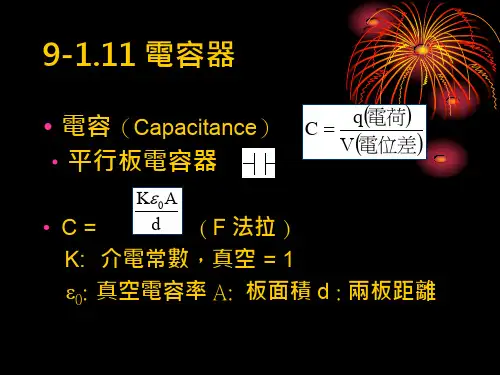
c. 电容的计算方法:讲解平行板电容器电容的计算公式,并引导学生进行推导。
3. 例题讲解:针对电容计算方法,选取典型例题进行讲解。
4. 随堂练习:让学生独立完成几道电容计算题目,巩固所学知识。
六、板书设计1. 电容器的概念、符号及种类。
2. 电容的计算公式。
3. 典型例题及解答步骤。
七、作业设计1. 作业题目:a. 计算给定平行板电容器的电容。
b. 分析一个实际电路中,电容器的作用。
2. 答案:八、课后反思及拓展延伸1. 反思:本节课学生对电容器的概念和电容的计算方法掌握程度,以及对实际应用的理解。
2. 拓展延伸:引导学生了解其他类型的电容器,以及电容器的其他应用领域,如振荡电路、滤波电路等。
重点和难点解析:1. 电容的物理意义。
2. 电容计算方法的推导和应用。
3. 电容器的实际应用。
4. 例题和随堂练习的选取与讲解。
5. 作业设计和答案的详尽性。
详细补充和说明:一、电容的物理意义电容的物理意义在于它能存储电荷,其容量大小反映了电容器在给定电压下存储电荷的能力。
18电容器电容课件高二上学期物理教科版一、教学内容本节课选自高二上学期物理教科版教材中第十八章“电容器与电容”一节。
详细内容包括:电容器的基本概念、电容的定义及其计算公式、电容器的连接方式及其电容值的计算、电容器的应用等。
二、教学目标1. 让学生了解电容器的结构、工作原理及其应用;2. 使学生掌握电容的定义、计算公式,并能正确运用;3. 培养学生运用电容器解决问题的能力,提高学生的实践操作技能。
三、教学难点与重点教学难点:电容器的连接方式及其电容值的计算;电容的定义及其计算公式的运用。
教学重点:电容器的基本概念;电容的计算及应用。
四、教具与学具准备1. 教具:电容器实物、示波器、信号发生器、电源等;2. 学具:电容计算器、练习册、笔、纸等。
五、教学过程1. 实践情景引入:展示电容器实物,引导学生观察电容器的结构,并提出问题:“电容器是什么?有什么作用?”2. 知识讲解:a. 电容器的基本概念及结构;b. 电容的定义、计算公式及其单位;c. 电容器的连接方式及其电容值的计算;d. 电容器的应用。
3. 例题讲解:讲解电容计算、电容器连接方式等典型例题,引导学生分析解题思路和方法。
4. 随堂练习:布置与电容计算、电容器连接相关的练习题,让学生当堂完成,并及时给予反馈。
六、板书设计1. 电容器的结构、工作原理;2. 电容的定义、计算公式、单位;3. 电容器的连接方式及其电容值的计算;4. 电容器的应用。
七、作业设计1. 作业题目:a. 计算给定电容器的电容值;b. 根据电容器的连接方式,计算总电容;c. 分析电容器在给定电路中的应用。
2. 答案:八、课后反思及拓展延伸1. 反思:本节课学生对电容器的结构、工作原理及电容的计算掌握情况较好,但部分学生对电容器连接方式的计算仍存在困难,需要在课后进行巩固;2. 拓展延伸:引导学生了解电容器的其他类型及其应用,如可变电容器、超级电容器等,激发学生的学习兴趣。
重点和难点解析1. 电容器的连接方式及其电容值的计算;2. 电容的定义及其计算公式的运用;3. 实践情景引入和例题讲解;4. 作业设计。
Chapter18 CapacitanceCapacitor is a device you can use to store energy as potential energy in an electric field. Capacitors also have many other uses in our electronic and microelectronic age. They are vital elements in the circuits with which we turn radio and television transmitters and receivers. Microscopic capacitors form the memory banks of computers.18.1 Capacitance1.The left figure shows some of the many sizes and shapes ofcapacitors. The right figure shows the basic elements of anycapacitor-two isolated conductors of arbitrary shape. No matter what their geometry, flat or not, we call these conductor plates.2.The following figure shows a less general but moreconventional arrangement, called a parallel-plate capacitor,consisting of two parallelconducting plates of area Aseparated by a distance d.The symbol that we use torepresent a capacitor is basedon the structure of aparallel-plate capacitor but is used for capacitors of all geometries.3.When a capacitor is charged, its plates have equal butopposite charge of +q and –q. However, we refer to the charge of a capacitor as being q, the absolute value of these charges on the plates.4.Because the plates are conductors, they are equipotentialsurfaces: all points on a plate are at the same electric potential.Moreover, there is a potential difference between the two plates. For historical reasons, we represent the absolute value of this potential difference with V.5.The charge q and the potential difference V for a capacitor areproportional to each other, That is, CVq . The proportionality constant C is called the capacitance of the capacitor. Its value depends only on the geometry of plates and not on their charge or potential difference.6. The SI unit of capacitance is coulomb per volt. This unit occurs so often that it is given a special name, the farad (F). The farad is a very large unit.Submultiples of the farad, such as themicrofarad (F F 6101-=μ) and thepicofarad (F pF 12101-=), are moreconvenient units in practice.7. Charging a Capacitor: See rightfigure.18.2 Calculating the capacitance1. There are four steps to calculate the capacitance of a capacitor:(1) assume a charge q on the plates; (2) calculate the electric field E between the plates in terms of this charge, usingGauss ’ law; (3) knowing E , calculate the potential differenceV between the plates ⎰-+=Eds V , in which the + and – remindus that our path of integration starts on the positive plate and ends on the negative plate; (4) calculate C.2. A parallel-plate capacitor : (1)A q σ= (2) 0εσ=E (3) 0εσdEd V == (4) dA d A V q C 00)/(εεσσ===. So the capacitance does indeed depend only on geometrical factors .3. A cylindrical capacitor : Figure shows, in cross section, a cylindrical capacitor of length Lformed by two coaxial cylindersof radii a and b. We assume thatb L >> so that we can neglect thefringing of the electric field thatoccurs at the ends of the cylinders. (1) Each plate contains a chargeof magnitude q. (2) Lr q E 02πε=. (3) )ln(2200a b L q r dr L q Eds V b a πεπε⎰⎰===-+. (4) )/ln(20a b L V q C πε==. We see that the capacitance of a cylindrical capacitor, like that of a parallel-plate capacitor, depends only on geometrical factors .4. A spherical capacitor : Figure can also serve as a central cross section of a capacitor that consists of two concentric spherical shells, of radii a and b. (1) Applying the Gauss ’ law, we have )4(200r E EA q πεε==, therefore (2) 204r qE πε=; (3) and then we have ab a b q r dr q V ba -==⎰02044πεπε. (4) Finally, ab ab C -=04πε. (5) An isolated sphere : we can assign a capacitance to a single isolated spherical conductor of radius R by assuming that the “missing plate ” is a conducting sphere of infinite radius . So R C 04πε=18.3 Storing Energy in An Electric Field1. Work must be done by an external agent to charge a capacitor . Starting with an uncharged capacitor, you remove electrons from one plate and transfer them one at a time to the other plate. The electric field that builds up in the space between the plates has a direction that tends to oppose further transfer. Thus as charge accumulates on the capacitor plates, you have to do increasingly large amounts of work to transfer additional electrons. We visualized the work required to charge a capacitor as being stored in the form of electric potential energy U in the electric field between the plates .2. Suppose that, at a given instant, a charge q ’ has been transferred from one plate to the other. The potential difference V ’ between the plates at that instant will be q ’/C. (1) If an extra increment of charge dq ’ is then been transferred, the increment of work required will be ''''dq Cq dq V dW ==. (2) The work required to bring the total capacitor charge up to a final value q is ⎰⎰===q C q dq q C dW W 022''1. (3) This work is stored as potential energy U in the capacitor so that22212CV or C q U ==. (4) The potential energy of a charged capacitor may be viewed as stored in the electric field between its plates.3. Energy density: (1) In a parallel-plate capacitor, neglecting fringing, the electric field has the same value for all points between the plates. Thus the energy density u , that is, the potential energy per unit volume between the plates , should also be uniform. (2) We can find u by dividing the total potential energy by the volume Ad of the space between the plates. 202020221)(212)/(2E d V Ad V d A Ad CV Ad U u εεε=====. (3) Although we derived this result for the special case of a parallel-plate capacitor, it holds generally, whatever may be the source of the electric field .18.4 Capacitor with a Dielectric1. If you fill the spacebetween the plates of acapacitor with adielectric , which is aninsulating material suchas mineral oil or plastic,Thecapacitance increased by anumerical factor κ,which is called the dielectric constant of the introducedmaterial. Table shows some dielectric materials and their dielectric constant.2. Another effect of the introduction of a dielectric is to limit the potential difference that can be applied between the plates to a certain value V max , called the breakdown potential . If this value is substantially exceeded, the dielectric material will break down and form a conducting path between the plates . Every dielectric material has a characteristic dielectric strength, which is the maximum value if the electric field that it can tolerate without breakdown. A few such values are list in the table.3. With a dielectric completely filling the space between the plates, the capacitance of a capacitor becomesair C C κ=, where air C is the value of the capacitance with only air between theplates.4. The effect of a dielectric can be summed up in more general terms: In a region completely filled by a dielectric material of dielectric constant κ, all electrostatics containing the permittivity constant 0ε are to be modified by replacing 0ε with 0εκ.18.5 Dielectrics: An Atomic ViewWhat happens, in atomic and molecular terms, when we put a dielectric in an electric field? There are two possibilities, depending on the nature of the molecules:1. Polar dielectrics: The molecules of some dielectrics, like water, have permanent electric dipole moments. In such materials (called polar dielectrics ), the electric dipoles tend to line upwith an external electric field as in above figure . The alignment of the electric dipoles produces an electric field that is opposite the applied field and smaller in magnitude than that field.2. Nonpolar dielectrics : (1) Figure (a) shows a nonpolardielectric slab with no external electric field applied. (2) In figure (b), an electric field0E is applied via a capacitor,whose plates are charged as shown. The effect of field 0E is aslight separation of the centers of the positive and negative charge distributions within the slab. The slab as a whole remains electrically neutral and –within the slab-there is no excess charge in any volume element. (3) Figure (c) shows that the induced surface charges on the faces produce an electric field'E in the direction opposite that of the applied electric field 0E . (4) The resultant fieldE inside the dielectric has the direction of 0E but is smaller in magnitude .3. Thus, the effect of both polar and nonpolar dielectrics is to weaken any applied field within them .18.6 dielectrics and Gauss ’ Law1. When we discuss the Gauss ’ law inchapter 16, we assumed that thecharges existed in a vacuum . Herewe shall see how to modify andgeneralize that law if dielectricmaterials are present. Right figureshows a parallel-plate capacitor ofplane area A, both with and without a dielectric. We assume that the charge q on the plates is the same in both situations.2. For the situation of figure (a), without a dielectric, we can find the electric field Aq E 00ε=. 3. In figure (b) with the dielectric in place, we can find the electric field between the plates by using the same Gauss ’ law.(1) However, now the surface encloses two types of charge: it still encloses charge +q on the top plate, but it now also encloses the induced charge –q ’ on the top face of the dielectric. The charge on the conducting plate is said to be free charge because it can move if we can change the electric potential of the plate. The net charge enclosed by the Gaussian surface in figure (b) is q-q’. (2) So, using Gauss ’ law, we have ⎰-==⋅'00q q EA A d E εε , or A q q E 0'ε-=. (3) The effect of thedielectric is to weaken the original field0E by the factor κ. So we may writeA q E E 00κεκ==. (4) Comparing above two equations, we have κq q q =-'. (5) By substituting for q-q ’ in the Gauss ’ law, we have ⎰=⋅)'(0dielectric with law Gauss q A d E κε. (6) This important equation, although derived for a parallel plate capacitor, is true generally and is the most general form in which Gauss ’ law can be written .4. Note that: (1) The flux integral now deals with E κ is sometimes called the electric displacementD , so that the11 Gauss ’ law can be written in the simplified form ⎰=⋅q A d D . (2) The charge q enclosed by the Gaussian surface is now taken to be the free charge only. The induced surface charge is deliberately ignored on the right side of this equation, having been taken fully into account by introducing the dielectric constant κ on the left side.。