3DViewer软件操作手册范本
- 格式:doc
- 大小:951.00 KB
- 文档页数:9

KDView软件V2.0.1 KDView软件V2.0.1用户手册广州市科缔智能科技有限公司二0二三年一月文件修改记录目录文件修改记录 (2)1.产品简介 (3)1.1产品概述 (3)1.2产品主要功能 (3)2.软件安装 (4)2.1运行环境要求 (4)2.2 获取软件 (4)3.软件操作说明 (5)3.1登录界面简介 (5)3.2 设备管理 (7)3.3 实时预览 (12)3.4 远程回放 (14)3.5 报警管理 (15)3.6 通用/功能设置 (17)3.7 图像浏览/分享 (19)3.8 个人中心 (21)3.9 注销登录 (22)3.10 语言切换 (22)1.产品简介1.1产品概述“KDView”监控软件为互联网时代最佳的手机视频监控解决方案,由前端采集设备、平台服务器和远程观看端三部分构成。
1.2产品主要功能主要功能:⚫注册登录、忘记密码⚫设备管理(添加、删除、修改、设置)⚫实时预览(对讲、转动摄像机、回放、报警信息)⚫远程回放(云存/SD卡)⚫报警管理⚫通用/功能设置⚫图像浏览和分享⚫个人中心(用户管理、系统设置、我的分享、关于)⚫注销登录⚫语言切换2.软件安装2.1运行环境要求苹果手机客户端要求ios9.0以上的系统;安卓手机客户端要求android 4.2及以上的系统。
2.2 获取软件苹果手机用户:在苹果应用市场(appstore)上搜索“KDView”安装。
安卓手机用户:在谷歌市场(google play)、应用宝、安卓市场等各大应用市场上搜索“KDView”安装。
3.软件操作说明3.1登录界面简介安装成功后,在程序列表点击KDView软件图标,软件就可以运行了。
启动程序进入登录界面,如图3.1a:⚫用户注册首次使用需要注册一个账号,该账户用于云存储我们的用户信息及相关设备列表,在登录菜单中,点击“注册账号”按钮,默认跳转到手机注册界面(如图3.1 b),点击右下角可切换到邮箱注册界面(图3.1 c),可点击左下角可切换回手机注册界面:图 3.1 b 图 3.1c⚫忘记密码在登录界面中,点击“忘记密码”按钮,跳转到“忘记密码”手机找回界面,可点击右下角的通过邮箱方式找回密码,可点击左下角可切换回手机找回密码界面。

Magic3DEasyView中文使用说明解读Magic 3D Easy View 软件使用说明序言我们的视觉效果软件可以为您设计的舞台场景提供3D立体效果图。
通过它,您可以预览机械灯具或智能灯具(iris灯、strobe灯等各种舞台灯)所拥有的功能,比如:灯光的运动、颜色和其他效果。
传统的灯具,包括PAR灯的效果也可以在软件中显示。
您可以加入道具来设计个性化舞台场景,比如:从我们的物料库中或是从其他的CAD软件中导入各种支撑架、舞台器具等等。
只需稍稍练习,您就可以设造一个逼真的舞台和场地。
注意:要得到精确的3D显示效果,必须细心建立舞台灯的资料库。
3D效果软件有不同模式,每个模式都可以通过不同的资源(软件、控制台、网络等等)接收DMX信号。
软件还可以同时显示4个DMX 域。
如果连接了一个软件控制器,软件就会自动地在3D软件中创建灯具地址,否则就需手动创建地址。
所有DMX域都遵循相同的规则。
另外,您也可以在软件中划分DMX域,比如域1连接到USB/DMX-IN 接口,而域2连接到Art-Net协议中。
3D软件中的DEMO模式可以让用户用最少的操作创建舞台场景。
但是不可以用这个模式将DMX信号连接到3D软件中。
第一步这一部分介绍了简单使用3D视窗的基本步骤。
它包括一个用来存储节目程序的描述文件和如何创造一个3D舞台场景的第一步。
3D舞台您所创建的3D舞台将会以*.evs 格式的文件被存储起来,并且您可以任意打开、修改及再存储这些文件。
您对舞台进行的所有设置,包括尺寸、颜色、花纹以及您所加入的各种灯光、道具和人物都会被保存在文件之中。
您同样可以在“舞台”的菜单栏中选择“导入/导出”选项,来将3D舞台导入到一个压缩文件中/将3D舞台从一个压缩文件中导出。
我们也可以存储一个舞台和它所需要的所有文件(比如背景图案的X 文件或bmp文件、jpg文件等等),并可以将它们在另一台没有这些文件的电脑上重新打开。
您的第一个舞台场景下面这部分阐述了如何创建第一个舞台的步骤,并向您介绍了3D 软件的基本功能。

三维高密度电法反演程序3D RES ver.2.2 for WIN98/Me/2000/XP/2003使用说明3DRES快速3-D 电阻率& IP 反演,使用最小二乘法;全中文操作界面,所有功能、操作说明都集成在对话框各提示框中,使你不需看说明书即可理解各项参数的意义及使用方法;支持的排列有温纳系列,三极、单-单极,双偶极,赤道双偶极等多种;支持视电阻率、电阻率、激电(时间域视极化率、频率域相位角、金属因子、频比率等);内置地形改正功能,数据中包含地形数据时,程序将自动作地形改正,结果可以带高程显示;特有的水下、水面、水陆解释功能;支持大网度三维勘探;多种格式兼容、转换,几何可以读取国内、外所有主要仪器输出数据;多种反演参数、反演方法,可让程序按你的要求得出最真实的结果;完善的数据监控、检测功能,能保证不让非法、错误或可疑的数据参与反演;多种结果显示方式,能让你从不同角度了解、分析反演结果;一切为结果的真实性考虑,是现有此类软件中最优秀的反演解释系统;配有相应的正演模型软件,可以为你工作装置及方法的选择提供帮助,和进行三维电成像研究。
简介3DRES用于处理三维电阻率成像测量(Li and Oldenburg 1992, White at al. 2001)数据,它能根据所测数据自动形成三维电阻率模型。
在这类测量中,电极按矩形网格排列(图1)。
需要强调一点,三维电成像测量并不仅仅是由一系列二维数据迭加而成,而是成熟的三维反演方法,有它自身的应用特点。
实际工作中使用的主要三维电极排列,如pole-pole, pole-dipole 和dipole-dipole等的情况在附录A, B 和C中有较详细的说明。
在有关的电成像测量教程(Loke 2002)中也可找到相关资料。
上面列出的几种排列是三维电成像测量中经常使用的排列,其他排列因为有效数据覆盖范围较少而很少使用。
当计算机拥有1.5 GB RAM时,本程序支持的网度可达到77 ×77 (或5929) 个电极点位!图 1. 一个三维电成像测量的排列示意图。
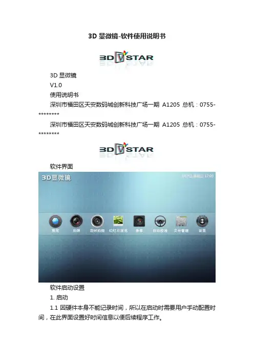
3D显微镜-软件使用说明书3D显微镜V1.0使用说明书深圳市福田区天安数码城创新科技广场一期A1205 总机:0755-********深圳市福田区天安数码城创新科技广场一期A1205 总机:0755-********软件界面软件启动设置1. 启动1.1 因硬件本身不能记录时间,所以在启动时需要用户手动配置时间,在此界面设置好时间信息以便后续程序工作。
软件功能说明1. 预览1.1. 预览功能1.1.1. 预览双摄像头的拍摄效果,如果感觉效果不好可以尝试6.1的“自动校准”。
2.拍照2.1.拍照功能2.1.1.点击拍摄按钮可以拍摄一张照片,并且在预览窗口显示缩略图。
点击缩略图可浏览拍摄的照片,左右滑动屏幕可以进行浏览照片操作。
3.定时拍摄深圳市福田区天安数码城创新科技广场一期A1205 总机:0755-********3.1.自动拍摄3.1.1.设置开始时间、结束时间、拍摄频率,程序会自动计算拍摄照片总张数以及磁盘空间是否存储所有图片,当磁盘空间不足以存储照片总数时任务将不能开始执行;3.1.2.频率可以设置“分钟”、“小时”、“天”为单位;3.1.3.触摸圆圈周边可以调节频度,程序会在“结束时间”的下方显示拍摄总照片数;3.1.4.点击“开始”按钮,设置仅此次有效并开始执行计划任务;3.1.5.点击“保存&开始”按钮,存储此次的配置并开始执行计划任务。
4.幻灯片浏览深圳市福田区天安数码城创新科技广场一期A1205 总机:0755-********深圳市福田区天安数码城创新科技广场一期A1205 总机:0755-********4.1. 此处显示3.1拍摄的照片,长按可以进行重命名和删除操作,点击可进行幻灯片浏览4.1.1. 可以在播放幻灯片时设置幻灯片的时间间隔,“+”增长时间间隔,“-”减少时间间隔;4.1.2. 可以在播放时进行暂停操作,点击“x ”退出当前幻灯片。
5.录像5.1.录像功能5.1.1.点击录像按钮后红色状态标识将会闪烁,系统开始录像,右侧的时间会以秒为单位标识拍摄时间总长度,此时暂停按钮可用,点击后可暂停录像,再次点击可以继续录像;5.1.2.在录像状态下点击录像按钮将结束录像。
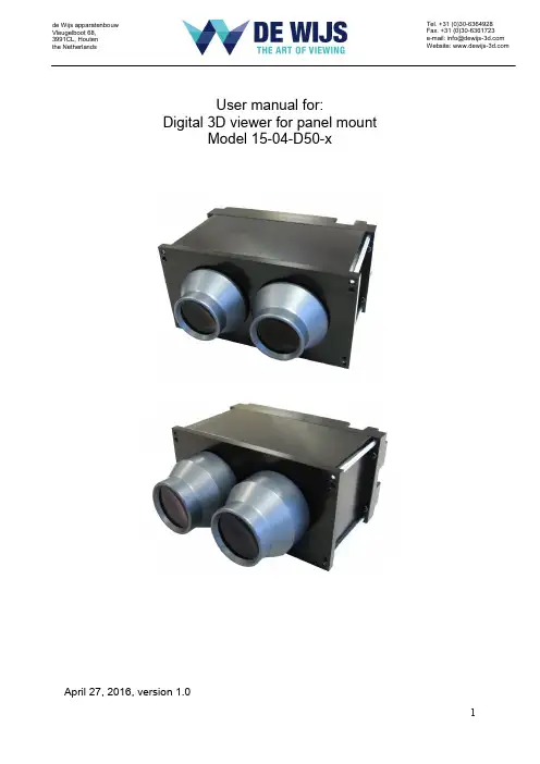
User manual for:Digital 3D viewer for panel mountModel 15-04-D50-xApril 27, 2016, version 1.0de Wijs apparatenbouwVleugelboot 68, 3991CL, Houten the NetherlandsTel. +31 (0)30-6364928 Fax. +31 (0)30-6361723 e-mail:******************Website: Table of contents.1. Introduction (3)1.1 Acknowledgements (3)2. Installation (4)2.1 The viewer (4)2.2 Caution required for the next points! (5)2.3 Content source (6)3 Technical data (7)3.1 Physical dimensions (120 mm. lens version) (7)3.2 Connectivity specifications (9)3.3 Digital video input specifications (timing) (9)3.4 Raspberry pi config.txt entries (10)3.5 Buttons and indicator LED explanation. (11)3.6 Maintenance (12)1. IntroductionAs we are currently speaking at the start of 2016, 3D or stereoscopic presentation of media on a private base is often achieved by VR like devices. These devices are good enough for the purpose of experiencing spectacular, interactive and an overwhelming depth experience. At the other side of the spectrum there are the 4K based passive or active glasses 3D TV’s with their crisp sharp image presentation. For exhibit or public environment 3D presentations both above mentioned products have disadvantages when it comes to poor image quality, control abilities and robustness. Because they are not made for that purpose.As de Wijs already has years of experience in building 3D slide viewing systems. The aim was to build a digital 3D viewer with the image quality that could compete with a good medium format slide viewer. However we made a compromise to meet to most specifications a exhibit / museum viewer should comply to. The resolution is not the highest currently available. The FHD LCD inside the viewer allowed us to easily control the viewer with simple single board computers or media players. Or, if needed, the viewer could be connected to a powerful desktop computer.This viewer is a good balance between optics and the resolution of the screen to present a high quality, sharp and optically comfortable show of 3D content. The aim was to design a visitor tolerant viewing system and reach people of all ages to experience your well prepared and high quality 3D images or video’s. The viewer is actually a monitor only and can be connected to any source having the ability to customize the video output resolution. The intention of this viewer is to build it into walls, panels or other custom build constructions.1.1 AcknowledgementsHugo de Wijs for his input on achromatic lenses, lens choices and 3D knowledge. Daniel Rozsnyó for the of the design and production of the HDMI to Mipi LCD controller.Ken Thompson for creating the open source presentation tool Pi-presents.The Raspberry pi foundation for creating such a small and very useful source for the viewer: 2. InstallationThe 3D digital viewer can be used to present a slide show or video. For exhibit designers, the viewer could be used as a stand-alone object or as ‘support’ to explain a scene or object close to the viewer.Because of the small size of the viewer, in most situations only the lens barrels are visible, the visitor should not overlook viewer and miss the presentation!When looking through the viewer, you get the best experience when there is nothing that is irritating or inhibits a clear view. Things that might irritate is bright spot lights pointing on the viewer causing the light to be reflected in your eyes. Or flashing lights close to the lenses. A black (cinema like) surrounding gives the best impression.2.1 The viewerThe viewer housing is constructed in such a way it gives the most freedom to integrate it in almost every situation.Integrating the viewer in your situation:- using the front panel plate is the easiest way to build the viewer in a wall or panel.- For your custom application, you can replace the front plate for your custom prepared front cover. Grooves in the side of the lens barrels allow to lock upyour front plate between the barrels and the housing of the viewer.2.2 Caution required for the next points!- Avoid sunlight to enter into the viewer through the lenses. The lenses act like burning glasses and the sun will damage the LCD inside. When you mount the viewer in a panel check if the sun would be able to point to the lenses at anytime of the day!- As long as the viewer is NOT build in on its final presentation location, cover the lenses to avoid accidentally burn-in of the LCD (point mentioned above).As well as protection against scratching the lenses.- The lenses are not fixed tight in the viewer housing to allow you to exchange the front plate for any reason, until you finish the build-in preparation. Secure the lenses to prevent unscrewing the lenses by the public.- The HDMI cable and micro USB cable are fragile connectors. The internal connectors of the LCD controller are mounted securely but allow limited force on the plug perpendicular to the insert of the plug. So always pull out the plug in-line with the connector. Use the cover at the rear of the viewer to be surethat forces on the cable will never result in a break-off of the internal smallconnectors.2.3 Content sourceThe viewer is build around a smart phone LCD display having the resolution of1080x1920 pixels with the size of 5”.The image data that is transferred through the HDMI cable needs to be arranged in such a way that the display is addressed as portrait orientated display instead of normal desktop landscape HD display. So 1080 pixels horizontally and 1920 pixels vertically.The choice of a content sources, filters out devices which are unable to deliver this vertical oriented resolution! Computer systems having a more advanced video processing output (separate video cards or graphic processors) are often automatically able to address this vertical display.Simple small single board computers, depending on the operating system, require more knowledge to address the vertical display.Be aware that there are a number of professional multimedia players are having fixed output resolutions to select from, that do not match with the vertical display!Using a single board computer like the Raspberry piDe Wijs offers a simple solution as content source; the Raspberry pi. The choice for this device has several reasons:- affordable and very good available.- The graphical output can easily be set to the required LCD configuration of the 3D viewer.- The General Purpose IO header on this board allows push buttons to control a slide show or start a video.- Open source software that can be adapted for your application.We use Pi-presents that gives a good solution for an interactive slide showwith acceptable performance.3 Technical data3.1 Physical dimensions (120 mm. lens version)Front view.Top viewWhen you consider tomake your own frontplate. You need tomake 2 holes side byHeart to heart distanceis 62 mm. and diameterof 56.5 mm. So whenfixing the lens barrelsinto the housing again,in the slot of the lensbarrels.Do NOT de-assemblethe long M4 bolts thattogether. You mightscratch the matt paintedinterior or LCD.Side view.The viewer can carry 2 types of lenses. Both fit in the housing of the viewer. Only thelength of the barrel is different:- 100 mm. achromatic, 33 mm. diameter. This lens magnifies 2.5x and is a goodchoice for viewing video content, having a 4:3 aspect ratio. The most upperand lower part of the LCD is less good visible for glasses wearers when usingthe full height of the LCD.- 120 mm. achromatic, 37 mm. diameter. This lens magnifies 2.1x and allows allvisitors to see the full size of the LCD into the corners without image distortion.Pixels are hard to see. It is a good choice for viewing square or landscape stillimages.LCD specifications:Sharp 4,97” LCD, model LS050T1SX01 FHD panel8 bits, visible area: 61,884x110,016 mm.There are 2 versions of this model, differences are minor. Both fit in the viewer.LCD Controller specifications:Controller board: RZSN0037, button board RZSN0038Firmware version 2015:3.2 Connectivity specificationsThe viewer has 2 power connectors; a DC connector and micro USBDC connector: 4,5 – 16 Volts dc. Round 5.5 mm. pin 2.1 mm. Micro USB connector: 5 Volts dc.Power consumption; 183mA at 12 Volts dc. 2,2 WattsDigital video input through the HDMI connector type A, 1.0 Edid version 1.3. Maximum cable length 1.5 metres.The LCD controller inside the viewer also holds some GPIO pins as well as for future usage like screen saver functions. It requires a firmware update.3.3 Digital video input specifications (timing)The graphical resolution of the LCD is(horizontal x vertical) 1080x1920 pixels at 60 Hz. 8 bits colour depth. The timing parameters are as following: Active Front Porch Sync width Back PorchActive field 1080x1920 pixels8 8 62 pixelsFront Porch 17 Sync Width 1 Back Porch 5 lineshdmi_timings=<h_active_pixels> <h_sync_polarity <h_front_porch> <h_sync_pulse><h_back_porch> <v_active_lines> <v_sync_polarity> <v_front_porch> <v_sync_pulse><v_back_porch> <v_sync_offset_a> <v_sync_offset_b> <pixel_rep> <frame_rate><interlaced> <pixel_freq> <aspect_ratio>hdmi_timings=<h_active_pixels> 1080<h_sync_polarity 0<h_front_porch> 8<h_sync_pulse> 8<h_back_porch> 62<v_active_lines> 1920<v_sync_polarity> 0<v_front_porch> 17<v_sync_pulse> 1<v_back_porch> 5<v_sync_offset_a> 0<v_sync_offset_b> 0<pixel_rep> 0<frame_rate> 60<interlaced> 0<pixel_freq> 135000000<aspect_ratio> 03.4 Raspberry pi config.txt entriesWhen choosing for the Raspberry pi as content source. The video output should be configured to control the 3D viewer. By default the Raspberry pi is not set correctly and won’t show any image in the viewer at all.The bellow entries are to be copied to the start-up config.txt file of the Raspberry pi to configure the video output to the right parametersdisable_overscan=1overscan_left=0overscan_right=0overscan_top=0overscan_bottom=0hdmi_force_hotplug=1hdmi_timings=1080 0 8 8 62 1920 0 17 1 5 0 0 0 60 0 135000000 0hdmi_group=2hdmi_mode=87max_framebuffer_width=1080max_framebuffer_height=1920display_rotate=3hdmi_ignore_edid=0xa50000803.5 Buttons and indicator LED explanation.Power up:When applying power to the viewer, the controller for the LCD starts up and tries to show an image on the LCD if the source is correct.Brightness buttons: ▲▼pressing these buttons at the rear of the viewer changes the brightness of the backlight of the LCD. The brightness level is stored after setting. When power is turned on or connected again, the latest brightness level is restored.To preserve the lifecycle of the LCD screen, it is good not to set the brightness of the LCD to maximum. Keep it to about 75%Power button:- Pressing the power button shortly, turns off the LCD backlight. The LCD itself is not turned off and the viewer still appears to be available for the source.- Pressing the power button long, will turn off the viewer completely.- Keeping the power button pressed and applying power will bring the viewer into service mode for updating the firmware.LED indicator behaviour:- Green continious: normal operation, correct signal on the HDMI input is applied.- Red continious: No cable connected, or no signal.- Orange: Viewer is initializing / configuring short after starting up. LCD controller is not ready yet.- Red blinking for 3 times short: wrong input signal / timing on HDMI.- Red blinking slowly: error inside the LCD controller of the viewer, restart required.3.6 MaintenanceCleaningThe outside of the viewer can be cleaned with regular cleaning liquids, not too aggressive or polishing. The lenses are not water tight. Clean the lenses with a soft cloth.Dust visible on the LCDTurn on the viewer to see the dust particles.Take the lens barrels out of the front of the viewer.You can blow with compressed air, not higher than 2 bars, inside the housing of the viewer towards the LCD. Not too deep and avoid touching the sides to prevent scratches on the inside walls.When re- assembling the lens barrels in the front, it might happen new particles drop on the LCD. You can repeat the above steps until the result is satisfying.Miss alignment of the image splitter.Between the left and right image on the LCD runs a thin metal plate from the LCD to your nose / between the eyes. This avoids the left or right eye to see parts of the image of the other side. The position of this splitter is accurate but might be, for some reason be out of alignment, you might see a very small piece of image of the other side (left or right).To resolve do the following:For whatever source you have, we supply a test image that looks like this:- Set your source to show the above image in the viewer.- Look through the lenses and see the direction and amount of miss alignment of the splitter (metal plate).- Now unscrew both lenses out of the housing.- With your fingers you can push the splitter (through the lens holes) to the left or right to get the splitter aligned. You actually bend the plate a little.- Check with the lenses if the alignment is right or repeat the previous step.- Clean the interior of the viewer with compressed air.- Re-assemble the lens barrels to the viewer and the alignment is finished.。

3DVison软件用户手册杭州先临三维科技股份有限公司目录1.前言 (2)2.3D Vision软件的安装 (3)3.3D Vision 的操作界面 (6)4.三维水晶人像制作流程 (7)5.工具栏按钮的功能 (8)6.编辑功能工具 (9)6.1 模型生成及导入导出 (9)6.2 模型平移、旋转、缩放 (13)6.3背景切除 (13)6.4 选择工具 (14)6.5清除毛刺 (16)6.6填补空洞 (16)6.7 表面光滑 (16)6.8 网格化 (16)6.9 刷新 (16)6.10复位 (16)6.11模型调整 (17)6.12模型删除 (17)6.13镜像工具 (18)6.14坐标系转换 (18)6.15点云操作 (18)6.16数据输出 (25)6.17快捷键 (26)7.3D Vision 的使用案例指导 (27)7.1 立体模型的处理 (27)7.2 平面照片的处理 (34)7.3 添加文字 (38)7.4添加配饰 (40)1.前言欢迎您使用杭州先临三维科技股份有限公司的三维成像软件3D-Vision。
本软件功能强大,界面简洁。
配合本公司研制的三维相机M1、M2,可以生成真实的立体模型,并对模型进行编辑,以实现各种用途。
同激光内雕机配合,制作三维立体人像水晶,是本软件的一个重要用途,在这项用途上,本软件具有如下主要优点:1.操作简便,可以快速生成三维人像的点云文件。
2.生成的数据效果好,使雕刻在水晶里的人像清晰、明亮、细腻。
3.具有强大的编辑功能,可以:对三维人像点云进行编辑处理,对二维照片进行点云编辑处理,添加文字,添加平面或者立体的个性化配饰,并进行组合编辑。
4.可以输出多种常规格式的数据,包括DXF(适用于主流的的激光内雕机),ASC,CAD,3DS(3DMAX),OBJ。
三维人像水晶内雕是一款经典的个性化礼品,将人们的真实形象定格在水晶之中,永不褪变,使人们一生中难忘和珍贵的时刻,成为恒久的记忆。

3D3操作手册目录1.系统配置1.1 计算机配置1.2 相机配置1.3 投影仪配置2. 软件安装,注册激活及升级2.1 软件安装2.2 软件激活更新2.2.1 激活秘钥2.2.2 加密狗秘钥2.2.3 激活加密狗2.2.4 激活控软件狗3. 系统搭建3.1 3D扫描仪硬件搭建3.2 计算机设置4. 扫描仪标定4.1 创建/打开标定文件4.1.1 创建新的标定文件4.1.2 打开已有标定文件4.2 标定过程4.2.1 标定设置4.2.2 相机设置4.2.3 settings Calibration4.2.4 获取标定图像4.2.5 获得标定结果5. 获取扫描数据5.1 建立/打开新的工程5.2 转台设置5.3 数据扫描5.3.1 用转台扫描数据5.3.2 手动扫描6. 数据处理6.1 编辑网格6.2 网格操作6.3 数据拼接6.3.1 Alignment——对齐6.3.2 Combine——合并6.3.3 Uncombine——解除合并6.3.4 Finalizing Meshes6.4 数据的导入和导出6.4.1 数据导入6.4.2 数据导出第一章、系统配置3D3Solutions公司推出的FlexScan3D Scanner是一套集软硬件为一体的三维扫面仪,通过结构白光投影方式解析物体表面三维信息,Scanner由投影仪、相机、软件、以及一系列附件构成。
1.1计算机配置1.2相机配置(1)3D扫描仪入门级相机选型推荐方案(价格优先)·单相机扫描仪:PTGrey Chameleon CMLN-13S2M-CS·双相机扫描仪:IDS uEye UI-1545LE·镜头:Fujinon 12.5mm C-Mount Lens(2)3D扫描仪中级用户相机推荐方案(扫描速度优先,适用于扫描面部和人体特征)·130W双/多相机扫描仪:PTGrey FireWire Flea2 FL2G-13S2M or FL2-14S3M ·130W双/多相机扫描仪:IDS uEye GigE UI-5240CP·镜头:Fujinon 12.5mm C-Mount Lens(3)3D扫描仪逆向工程开发级相机推荐方案(精度、分辨率优先)·2M双相机扫描仪:PTGrey Grasshopper GRAS-20S4M-C·2M双相机扫描仪:Duo scanner setup: IDS uEye GigE UI-6250SE·镜头:5MP Fujinon 12.5mm C-Mount Lens1.3投影仪配置最低分辨率:800x600标准投影仪:1500+流明基于DLP(Digital Light Procession)技术LED投影仪:100+流明对比LED投影仪和普通正常投影仪:(1)LED投影仪优势:发热低;体积小巧;使用寿命长(LED投影仪30,000小时,普通白光投影仪3,000小时)(2)LED投影仪劣势分辨率、扫描精度、数据质量比较低;低光照,在复杂环境光影响下无法扫描;扫描黑色物体和高对比物体比较困难;选型局限性大。
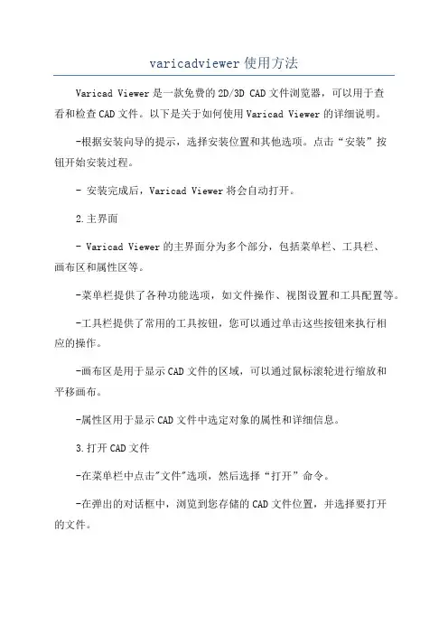
varicadviewer使用方法Varicad Viewer是一款免费的2D/3D CAD文件浏览器,可以用于查看和检查CAD文件。
以下是关于如何使用Varicad Viewer的详细说明。
-根据安装向导的提示,选择安装位置和其他选项。
点击“安装”按钮开始安装过程。
- 安装完成后,Varicad Viewer将会自动打开。
2.主界面- Varicad Viewer的主界面分为多个部分,包括菜单栏、工具栏、画布区和属性区等。
-菜单栏提供了各种功能选项,如文件操作、视图设置和工具配置等。
-工具栏提供了常用的工具按钮,您可以通过单击这些按钮来执行相应的操作。
-画布区是用于显示CAD文件的区域,可以通过鼠标滚轮进行缩放和平移画布。
-属性区用于显示CAD文件中选定对象的属性和详细信息。
3.打开CAD文件-在菜单栏中点击"文件"选项,然后选择“打开”命令。
-在弹出的对话框中,浏览到您存储的CAD文件位置,并选择要打开的文件。
- 单击“打开”按钮,Varicad Viewer将加载并显示所选的CAD文件。
4.导航和查看-使用鼠标滚轮可以放大或缩小CAD文件画布。
-按住鼠标左键并移动鼠标可以平移画布。
-使用菜单栏或工具栏中的按钮可以旋转和翻转CAD文件的视图。
-使用导航工具栏可以在不同的视图模式之间切换,如平面视图、立体视图和截面视图等。
5.CAD文件的浏览和检查-使用菜单栏中的测量工具可以测量CAD文件中的长度、角度和其他尺寸。
-使用菜单栏中的剖面工具可以在CAD文件中创建剖面图。
6.文件操作和设置-使用菜单栏中的“文件”选项可以执行文件的打开、保存和另存为操作。
-使用菜单栏中的“视图”选项可以设置CAD文件的显示方式,如图层、阴影和实体显示等。
-使用菜单栏中的“工具”选项可以配置工具栏、快捷键和其他参数设置。
7.高级功能- Varicad Viewer还提供了一些高级功能,例如批注、轨迹漫游和动态剖面等。

3DViewer6软件操作手册1、双击打开3DViewer6文件夹中的3DViewer.exe可执行文件,打开的界面如下图:图1 3Dviewer初始界面2、依次点击菜单栏中的:文件—>打开DEM数据—>打开DEM文件,这样就打开一个弹出窗口,选择路径,路径为解压文件jiaohe.rar存放的路径,选择该文件下的jiaohe_move_2.dem文件,如下图所示:图2 打开dem路径图3 选择dem路径场景示意图如下:图4 打开dem后的场景3、点击菜单栏中的:文件—>打开DOM数据—>打开DOM文件,这样就打开一个弹出窗口,打开jiaohe.bmp文件。
场景示意图如下:图5 打开dom操作图6 选择dom路径图7 打开dom后的场景3、点击菜单栏中的:文件—>打开模型数据—>打开三维工作区文件,这样就打开一个如下图的弹出窗口。
图8 打开三维场景图9 打开工作区路径打开上图中选中的,打开该文件夹中JiaoHe.CGS文件。
5、点击菜单栏中的:参数设置—>模型显示方式—>景观图。
图10 点击景观图点击软件左边树状图中的左边的,请稍等,现在场景在加载数据,大概几十秒后,数据加载完毕,具体时间视电脑配置情况,场景示意图如下:图11 打工作区后的场景6、场景操作如下:从左到右依次为:放大操作、拉框放大操作、缩小操作、旋转操作、移动操作(另外也可以滚动鼠标中键进行放大或者缩小操作)。
注意:若是机器上装有vc6.0,可以通过以下操作提高3DVIEWER的浏览与操作速:1、将C:\boot.ini 文件做如下修改:[boot loader]timeout=30default=multi(0)disk(0)rdisk(0)partition(2)\WINDOWS[operating systems]multi(0)disk(0)rdisk(0)partition(2)\WINDOWS="Microsoft Windows XP Professional" /3GB2、若vc6.0的安装目录为D:\Program Files\Microsoft Visual Studio 8 ,则目录下D:\Program Files\Microsoft Visual Studio 8\VC\bin找到editbin 这个可执行文件,然后进行以下操作①点击电脑的,在弹出的面板上点击②在点击“运行”后,会弹出的面板如下图左,输入“cmd”③上一步操作后会弹出则输入“cd D:\Program Files\Microsoft Visual Studio 8\VC\bin”,如下图④然后输入editbin /LARGEADDRESSAWARE yourapplication.exe 这里的yourapplication.exe 需要输入的是你的3DViewer程序的路径名加文件名。
3D系统操作说明书第一章系统介绍 (2)1.1 系统整体功能 (2)1.2 系统2D模式下的功能 (2)1.3 系统3D模式下的功能 (3)第二章 2D模式操作 (5)2.1 2D模式操作界面介绍 (5)2.2绘制房型 (6)2.2.1 线条工具绘制户型 (6)2.2.2 “拖房型“绘制户型 (7)2.3 添加窗户 (8)2.4 添加房门 (8)第三章 3D模式操作 (10)3.1 家具、家居装饰以及建材菜单介绍 (11)3.2 设置家具、家居装饰以及建材 (13)3.3 视图模式 (14)3.3.1 鸟瞰视图模式 (14)3.3.2 顶视图模式 (15)3.3.3 漫游视图模式 (16)3.4 替换材质 (16)第四章户型保存操作 (18)4.1 用户注册和登录 (18)4.2 设计保存、另存操作 (18)4.3 户型管理 (21)第一章系统介绍1.1 系统整体功能本系统是基于Unity3D平台上的二次开发的三维室内制作软件,通过使用该系统,用户可以根据自己的需求制作风格迥异的房间、户型,并且可以为房间的布局进行设置。
本系统中为用户提供了多类型的家居、厨具、家居装饰以及建材等模型,方便用户为自己设计一个理想中的“家”,并且可以在这个“家”中进行三维的全景浏览。
该系统以网页版格式发布,版权归格家美居平台所有,用户可通过格家美居平台的平台商城进入该系统,点击“立即开始定制”即可进入系统,入口界面如图1-1所示:图1-1 3D系统的入口1.2 系统2D模式下的功能在2D模式下,用户可以设计房子的户型:根据自身需求与选择,用户可设置设置房间的个数、尺寸,阳台的大小和位置,窗户以及门的类型选择以及摆放位置,如图1-2所示:图1-2 绘制好的户型1.3 系统3D模式下的功能在3D模式下,用户即可在已建立好户型的基础上,为房间摆放各种类型的家具用品如床,沙发,厨具,灯饰等,也提供了家居装饰和建材的选择。
即可为用户打造一个理想中的房子造型,如图1-3所示:图1-3 构造好的房子温馨提示:当用户初次进入我们的3D整体定制系统页面的时候,若用户计算机上未安装有Unity3D这一款软件,则会出现用户安装三维定制浏览插件的消息提示,此时,用户只需点击安装,安装完成之后即可进入我们的3D系统,如图1-4所示:图1-4 三维定制浏览插件安装提示第二章 2D模式操作操作界面图如图2-1所示:图2-1 2D模式操作界面2.1 2D模式操作界面介绍如图2-1所示,系统的2D操作界面与一般的软件大同小异。
Package‘cubeview’October12,2022Type PackageTitle View3D Raster Cubes InteractivelyVersion0.2.0Date2019-09-23Maintainer Tim Appelhans<***********************>Description Creates a3D data cube view of a RasterStack/Brick,typically acollection/array of RasterLayers(along z-axis)with the same geographicalextent(x and y dimensions)and resolution,provided by package'raster'.Slices through each dimension(x/y/z),freely adjustable in location,are mapped to the visible sides of the cube.The cube can be freely rotated.Zooming and panning can be used to focus on different areas of the cube.License MIT+file LICENSEEncoding UTF-8Depends R(>=2.10)Imports base64enc,htmltools,htmlwidgets,lattice,raster,stars,viridisLiteSuggests methods,shinyLazyData trueRoxygenNote6.1.1NeedsCompilation noAuthor Tim Appelhans[cre,aut],Stefan Woellauer[aut],three.js authors[ctb,cph](three.js library)Repository CRANDate/Publication2019-09-2407:20:02UTCR topics documented:cubeview (2)cubeViewOutput (3)Index512cubeview cubeview View a RasterStack or RasterBrick as3-dimensional data cube.DescriptionCreates a3D data cube view of a RasterStack/Brick.Slices through each dimension(x/y/z)are mapped to the visible sides of the cube.The cube can be freely rotated.Zooming and panning can be used to focus on different areas of the cube.See Details for information on how to control the location of the slices and all other available keyborad and mouse guestures to control the cube.Usagecubeview(x,...)##S3method for class charactercubeview(x,at,col.regions=viridisLite::inferno,na.color="#BEBEBE",legend=TRUE,...)##S3method for class starscubeview(x,at,col.regions=viridisLite::inferno,na.color="#BEBEBE",legend=TRUE,...)##S3method for class Rastercubeview(x,at,col.regions=viridisLite::inferno,na.color="#BEBEBE",legend=TRUE,...)cubeView(x,...)Argumentsx afile name,stars object,RasterStack or RasterBrick...additional arguments passed on to read_stars.at the breakpoints used for the visualisation.See levelplot for details.col.regions either a palette function or a vector of colors to be used for palette generation.na.color color for missing values.legend logical.Whether to plot a legend.DetailsThe location of the slices can be controlled by keys:x-axis:LEFT/RIGHT arrow keyy-axis:DOWN/UP arrow keyz-axis:PAGE_DOWN/PAGE_UP keyOther controls:Press and hold left mouse-button to rotate the cube.Press and hold right mouse-button to move the cube.Spin mouse-wheel or press and hold middle mouse-button and move mouse down/up to zoom the cube.Press space bar to show/hide slice position guides.Note:In RStudio cubeView may show a blank viewer window.In this case open the view in a web-browser (RStudio button at viewer:"show in new window").Note:Because of key focus issues key-press-events may not always recognised within RStudio on Win-dows.In this case open the view in a web-browser(RStudio button at viewer:"show in new window").Author(s)Stephan Woellauer and Tim AppelhansExamplesif(interactive()){library(raster)library(stars)##directly from filekili_data<-system.file("extdata","kiliNDVI.tif",package="cubeview")cubeview(kili_data)##stars objectkili_strs=read_stars(kili_data)cubeview(kili_strs)##rsater stack(also works with brick)kili_rstr<-stack(kili_data)cubeview(kili_rstr)##use different color palette and set breaksclr<-viridisLite::viridiscubeview(kili_data,at=seq(-0.15,0.95,0.1),col.regions=clr)}cubeViewOutput Widget output/render function for use in ShinyDescriptionWidget output/render function for use in ShinyUsagecubeViewOutput(outputId,width="100%",height="400px")renderCubeView(expr,env=parent.frame(),quoted=FALSE)ArgumentsoutputId Output variable to read fromwidth,height the width and height of the map(see shinyWidgetOutput)expr An expression that generates an HTML widgetenv The environment in which to evaluate exprquoted Is expr a quoted expression(with quote())?This is useful if you want to save an expression in a variableExamplesif(interactive()){library(shiny)library(raster)kili_data<-system.file("extdata","kiliNDVI.tif",package="cubeview")kiliNDVI<-stack(kili_data)cube=cubeView(kiliNDVI)ui=fluidPage(cubeViewOutput("cube",width=300,height=300))server=function(input,output,session){output$cube<-renderCubeView(cube)}shinyApp(ui,server)}IndexcubeView(cubeview),2cubeview,2cubeViewOutput,3levelplot,2read_stars,2renderCubeView(cubeViewOutput),3 shinyWidgetOutput,45。
生物梅里埃操作手册版本:B.00生物梅里埃公司Box 15969, Durham, NC 27704-0969生物梅里埃公司2001 手册件号. 43001-19 版本. A 2002年2月BacT/ALERT® 3D™版权所有。
未经生物梅里埃公司书面许可,本文件的任何部分都不允许复制。
ASTM是美国材料实验协会的商标。
BacT/ALERT, BacT/LINK, BacT/VIEW和MB/BacT是生物梅里埃公司在美国和其他国家的注册商标。
BacT/ALERT 3D是生物梅里埃公司的商标。
Lexan是通用电器公司的注册商标。
MicroNET是生物梅里埃公司的注册商标。
MS DOS是微软公司的注册商标。
PSC是PSC公司的注册商标。
Zip是Iomega公司的注册商标。
i第 1 章系统概览目录部分页码1.1 BacT/ALERT 3D 硬件1.1.1 BacT/ALERT 3D………………………………………………………………………….1.21.1.2 BacT/ALERT 3D 规格…………………………………………………………………...1.41.1.3 BacT/ALERT 3D 环境要求……………………………………………………………...1.41.1.4 孵育模块………………………………………………………………………………….1.51.1.5 孵育模块规格…………………………………………………………………………….1.61.1.6 孵育模块环境要求……………………………………………………………………….1.71.1.7 仪器安装和设置………………………………………………………………………….1.71.2 BACT/ALERT 3D 软件1.2.1 操作面板………………………………………………………………………………….1.81.2.2 普通屏幕元素…………………………………………………………………………….1.81.11.1.1 BacT/ALERT 3D图1-1 BacT/ALERT 3D 前视图操作面板提供一种显示信息的方法。
绘图与航空影像处理软件用户手册版本2.3.7目录1系统简介 (1)2系统要求 (2)3使用说明 (4)3.1欢迎界面 (4)3.2工具栏和工作面板 (4)3.3视图窗口与实时命令窗口 (6)4工作流程 (8)4.1系统介绍 (8)4.2数据准备 (8)4.3数据处理 (10)4.3.1影像载入 (10)4.3.2光束法平差 (13)4.3.3地理定向 (14)4.3.4模型重建 (20)5建模与分析 (22)5.1点云操作 (22)5.1.1点云渲染 (23)5.1.2点云捕捉 (23)5.1.3视图展示 (24)5.1.4点云选择 (26)5.1.5点云删除 (26)5.1.6点云操作 (27)5.1.7剖面线计算 (28)5.1.8点云拼接 (37)5.1.9高度图展示 (38)5.1.10点云删除 (38)5.1.11点云拾取 (38)5.1.12点云保存 (39)5.1.13地形点分类 (39)5.2DSM操作 (41)5.2.1数字表面模型计算 (41)5.2.2数字正射影像叠加 (43)5.2.3网格显示 (44)5.2.4格网线展示 (44)5.2.5数据展平 (44)5.2.6体积计算 (45)5.2.7等高线计算 (48)5.2.8数据删除 (50)5.3DOM操作 (50)5.3.1数字正射影像计算 (50)5.3.2数字正射校正 (51)5.3.3DOF剪裁 (53)5.3.4影像拼接 (54)5.3.5面积计算 (56)5.3.6数据删除 (56)6系统报告 (57)1系统简介3Dsurvey是一个测绘与航空影像处理系统集成解决方案。
通过该软件,您可以将通过无人机和其他航空设备获取的二维影像和空间数据来建立专业的三维模型。
3Dsurvey提供摄影测量处理(空三测量、定位定向、模型重建)、三维建模和数据分析(三维勘测产生的摄影测量点云和第三方源数据如las、LiDAR、CAD等)的功能。
viewpower版本中文操作手册范本摘要:一、前言二、ViewPower版本概述1.ViewPower的定义2.ViewPower版本的发展历程三、ViewPower版本的功能特点1.强大的数据处理能力2.高度的可视化定制3.便捷的操作体验四、ViewPower版本的操作指南1.安装与配置2.数据导入与处理3.可视化界面定制4.数据导出与分享五、ViewPower版本的常见问题与解决方案六、总结与展望正文:一、前言ViewPower是一款面向未来的数据可视化工具,广泛应用于各行各业,帮助用户轻松处理海量数据,实现数据的价值。
本文将详细介绍ViewPower版本的相关内容,包括版本概述、功能特点、操作指南以及常见问题与解决方案。
二、ViewPower版本概述1.ViewPower的定义ViewPower是一款以数据可视化为核心,集数据处理、分析和展示于一体的强大工具。
它能够帮助用户快速将海量数据转换为易于理解的图表和报告,从而实现对数据的深度洞察。
2.ViewPower版本的发展历程ViewPower自问世以来,经历了多个版本的迭代更新。
每个版本都在原有基础上进行了功能优化和拓展,为用户提供了更加完善的使用体验。
三、ViewPower版本的功能特点1.强大的数据处理能力ViewPower版本具备强大的数据处理能力,支持多种数据源的导入与处理,包括Excel、CSV、数据库等。
此外,ViewPower还支持数据预处理功能,如数据清洗、去重、格式转换等,确保数据的准确性和完整性。
2.高度的可视化定制ViewPower版本提供了丰富的可视化图表类型,如柱状图、饼图、地图等,用户可以根据自己的需求选择合适的图表进行展示。
此外,用户还可以自定义图表样式、颜色、标签等,实现高度的可视化定制。
3.便捷的操作体验ViewPower版本采用了简洁直观的操作界面,用户可以轻松上手。
同时,ViewPower还提供了丰富的快捷键和工具栏,方便用户快速完成各种操作。
3DVison软件用户手册杭州先临三维科技股份有限公司目录1.前言 (2)2.3D Vision软件的安装 (3)3.3D Vision 的操作界面 (6)4.三维水晶人像制作流程 (7)5.工具栏按钮的功能 (8)6.编辑功能工具 (9)6.1 模型生成及导入导出 (9)6.2 模型平移、旋转、缩放 (13)6.3背景切除 (13)6.4 选择工具 (14)6.5清除毛刺 (16)6.6填补空洞 (16)6.7 表面光滑 (16)6.8 网格化 (16)6.9 刷新 (16)6.10复位 (16)6.11模型调整 (17)6.12模型删除 (17)6.13镜像工具 (18)6.14坐标系转换 (18)6.15点云操作 (18)6.16数据输出 (25)6.17快捷键 (26)7.3D Vision 的使用案例指导 (27)7.1 立体模型的处理 (27)7.2 平面照片的处理 (34)7.3 添加文字 (38)7.4添加配饰 (40)1.前言欢迎您使用杭州先临三维科技股份有限公司的三维成像软件3D-Vision。
本软件功能强大,界面简洁。
配合本公司研制的三维相机M1、M2,可以生成真实的立体模型,并对模型进行编辑,以实现各种用途。
同激光内雕机配合,制作三维立体人像水晶,是本软件的一个重要用途,在这项用途上,本软件具有如下主要优点:1.操作简便,可以快速生成三维人像的点云文件。
2.生成的数据效果好,使雕刻在水晶里的人像清晰、明亮、细腻。
3.具有强大的编辑功能,可以:对三维人像点云进行编辑处理,对二维照片进行点云编辑处理,添加文字,添加平面或者立体的个性化配饰,并进行组合编辑。
4.可以输出多种常规格式的数据,包括DXF(适用于主流的的激光内雕机),ASC,CAD,3DS(3DMAX),OBJ。
三维人像水晶内雕是一款经典的个性化礼品,将人们的真实形象定格在水晶之中,永不褪变,使人们一生中难忘和珍贵的时刻,成为恒久的记忆。
3DViewer6软件操作手册
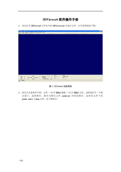
1、双击打开3DViewer6文件夹中的3DViewer.exe可执行文件,打开的界面如下图:
图1 3Dviewer初始界面
2、依次点击菜单栏中的:文件—>打开DEM数据—>打开DEM文件,这样就打开一个弹
出窗口,选择路径,路径为解压文件jiaohe.rar存放的路径,选择该文件下的jiaohe_move_2.dem文件,如下图所示:
图2 打开dem路径
图3 选择dem路径场景示意图如下:
图4 打开dem后的场景
3、点击菜单栏中的:文件—>打开DOM数据—>打开DOM文件,这样就打开一个弹出窗口,打开jiaohe.bmp文件。
场景示意图如下:
图5 打开dom操作
图6 选择dom路径
图7 打开dom后的场景
3、点击菜单栏中的:文件—>打开模型数据—>打开三维工作区文件,这样就打开一个如下
图的弹出窗口。
图8 打开三维场景
图9 打开工作区路径
打开上图中选中的,打开该文件夹中JiaoHe.CGS文件。
5、点击菜单栏中的:参数设置—>模型显示方式—>景观图。
图10 点击景观图
点击软件左边树状图中的左边的,请稍等,现在场景在加载数据,大概几十秒后,数据加载完毕,具体时间视电脑配置情况,场景示意图如下:
图11 打工作区后的场景
6、场景操作如下:
从左到右依次为:放大操作、拉框放大操作、缩小操作、旋转操作、移动操作(另外也可以滚动鼠标中键进行放大或者缩小操作)。
注意:
若是机器上装有vc6.0,可以通过以下操作提高3DVIEWER的浏览与操作速:
1、将C:\boot.ini 文件做如下修改:
[boot loader]
timeout=30
default=multi(0)disk(0)rdisk(0)partition(2)\WINDOWS
[operating systems]
multi(0)disk(0)rdisk(0)partition(2)\WINDOWS="Microsoft Windows XP Professional" /3GB
2、若vc6.0的安装目录为D:\Program Files\Microsoft Visual Studio 8 ,则目录下D:\Program Files\Microsoft Visual Studio 8\VC\bin找到editbin 这个可执行文件,然后进行以下操作
①点击电脑的,在弹出的面板上点击
②在点击“运行”后,会弹出的面板如下图左,输入“cmd”
③上一步操作后会弹出
则输入“cd D:\Program Files\Microsoft Visual Studio 8\VC\bin”,如下图
④然后输入editbin /LARGEADDRESSAWARE yourapplication.exe 这里的
yourapplication.exe 需要输入的是你的3DViewer程序的路径名加文件名。
比如如果你的3DViewer.exe放在D盘的3DViewer文件夹下,您就输入
editbin /LARGEADDRESSAW ARE D:/ 3DViewer/3DViewer.exe。