Gerix_Wifi_Cracker详细使用教程
- 格式:docx
- 大小:200.58 KB
- 文档页数:5
【推荐下载】jcg捷希路由器怎么设置-实用word文档
本文部分内容来自网络整理,本司不为其真实性负责,如有异议或侵权请及时联系,本司将立即删除!
== 本文为word格式,下载后可方便编辑和修改! ==
jcg捷希路由器怎么设置
JCG路由器,其“智能”是指“像个人电脑一样,具有独立的操作系统,可以由用户自行安装,自行控制带宽,自行控制在线人数,自行控制浏览网页,自行控制在线时间”的一系列功能。
下面是小编帮大家整理的jcg捷希路由器
怎么设置,希望大家喜欢。
工具/原料
电脑网线
捷希智能路由器
方法/步骤
首先给JCG捷希无线路由器通电,用网线连接无线路由器和电脑。
关掉无
线网络,开启本地连接。
查看无线路由器的IP地址,然后在网页上输入IP地址,默认IP地址为192.168.1.1
回车进入无线路由器的设置页面点快速安装向导
输入默认管理用户名和密码,用户名admin, 密码admin 点确定
点下一步
我用的是电信的,选择PPPOE需要输入账号和密码,其他网络运营商的,
按照网络运营商提供的资料选择DHCP或者固定IP地址,填写完点下一步
一般情况下设置都是默认的,频射开关选择开启,频射工作模式选择混合,SSID是无线网络的用户名,可根据自己的意愿更改,
注意要设置成中文。
隐藏选择停用,频道可以自由选择,一般情况下默认频道是
设置完成后点下一步,点应用,初步设置就算完成了
系统会重启。
Giiaker操作说明
一、概述
Giiaker是一款对智能硬件的连接工具,它可以帮助用户使用智能硬件进行智能控制、信息格式化、数据可视化等操作。
2G/3G/4G/Wi-Fi等无线网络可以通过Giiaker连接智能硬件,从而满足各种智能控制需求。
二、安装Giiaker
2.安装Giiaker,参照Giiaker的安装引导安装Giiaker软件,安装完成后点击安装后页面的“进入Giiaker”按钮,安装成功。
三、Giiaker的使用
2.新建项目,点击“新建项目”,根据所需的模块拖拽,建立所需项目。
3.连接设备,点击右上角设备按钮,可进行设备连接,设备连接成功后可以进行各种操作。
5.运行项目,进入运行界面,点击右上角运行按钮,可以实时查看设备信息,实时调节参数,实时观察智能硬件运行情况,防止智能硬件出现异常。
6.可视化,可以对智能硬件的数据进行可视化处理。
完全教程Aircrack其实关于无线基础知识的内容还是挺多的,但是由于本书侧重于BT4自身工具使用的讲解,若是再仔细讲述这些外围的知识,这就好比讲述DNS工具时还要把DNS服务器的类型、工作原理及配置讲述一遍一样,哈哈,估计整本书的厚度就需要再翻一、两倍了。
恩,关于无线网络基础知识建议大家可以参考我之前在黑手这里出版的《无线黑客傻瓜书》一书,会很有帮助。
恩,先说明一下,本章的内容适用于目前市面所有主流品牌无线路由器或AP如Linksys、Dlink、TPLink、BelKin等。
涉及内容包括了WEP加密及WPA-PSK加密的无线网络的破解操作实战。
◆什么是Aircrack-ngAircrack-ng是一款用于破解无线802.11WEP及WPA-PSK加密的工具,该工具在2005年11月之前名字是Aircrack,在其2.41版本之后才改名为Aircrack-ng。
Aircrack-ng主要使用了两种攻击方式进行WEP破解:一种是FMS攻击,该攻击方式是以发现该WEP漏洞的研究人员名字(Scott Fluhrer、Itsik Mantin及Adi Shamir)所命名;另一种是KoreK攻击,经统计,该攻击方式的攻击效率要远高于FMS攻击。
当然,最新的版本又集成了更多种类型的攻击方式。
对于无线黑客而言,Aircrack-ng是一款必不可缺的无线攻击工具,可以说很大一部分无线攻击都依赖于它来完成;而对于无线安全人员而言,Aircrack-ng也是一款必备的无线安全检测工具,它可以帮助管理员进行无线网络密码的脆弱性检查及了解无线网络信号的分布情况,非常适合对企业进行无线安全审计时使用。
Aircrack-ng(注意大小写)是一个包含了多款工具的无线攻击审计套装,这里面很多工具在后面的内容中都会用到,具体见下表1为Aircrack-ng包含的组件具体列表。
表1Aircrack-ng在BackTrack4 R2下已经内置(下载BackTrack4 R2),具体调用方法如下图2所示:通过依次选择菜单中“Backtrack”—“Radio Network Analysis” —“80211”—“Cracking”—“Aircrack-ng ”,即可打开Aircrack-ng的主程序界面。
路由器密码破译方法摘要:一、路由器密码破译方法概述二、路由器密码破译工具及操作步骤三、防范路由器密码被破解的方法四、总结正文:路由器作为家庭和企业网络的核心设备,其安全性能备受关注。
本文将介绍路由器密码破译的方法、工具及防范措施,以帮助大家提高网络安全意识。
一、路由器密码破译方法概述路由器密码破译主要包括两种方式:暴力破解和字典破解。
暴力破解是通过不断尝试密码组合,利用计算能力破解路由器密码;字典破解则是利用密码字典文件,尝试将字典中的单词组合作为密码进行登录。
此外,还有一些高级的破解方法,如彩虹表攻击、穷举法等。
二、路由器密码破译工具及操作步骤1.工具选择:为了方便演示,本文将使用John the Ripper这款开源密码破解工具。
2.操作步骤:(1)安装John the Ripper:在命令行界面输入“pip install john”命令进行安装。
(2)获取路由器管理界面:输入命令“telnet 路由器IP地址”,进入路由器管理界面。
(3)使用John the Ripper进行破解:输入命令“john -u 用户名-p 密码字典文件”,如“john -u root -p /usr/share/wordlist/rockyou.txt”。
三、防范路由器密码被破解的方法1.设置复杂密码:使用字母、数字、特殊符号组合的密码,提高破解难度。
2.定期更改密码:建议每隔一段时间更换一次密码,降低被破解的风险。
3.关闭远程管理:禁用远程管理功能,减少攻击面。
4.开启加密认证:启用SSH加密传输,提高安全性。
5.更新路由器固件:定期更新路由器固件,修复已知漏洞。
四、总结路由器密码破译虽然存在一定的风险,但通过加强安全意识、设置复杂密码、定期更改密码等方法,可以有效降低被破解的可能性。
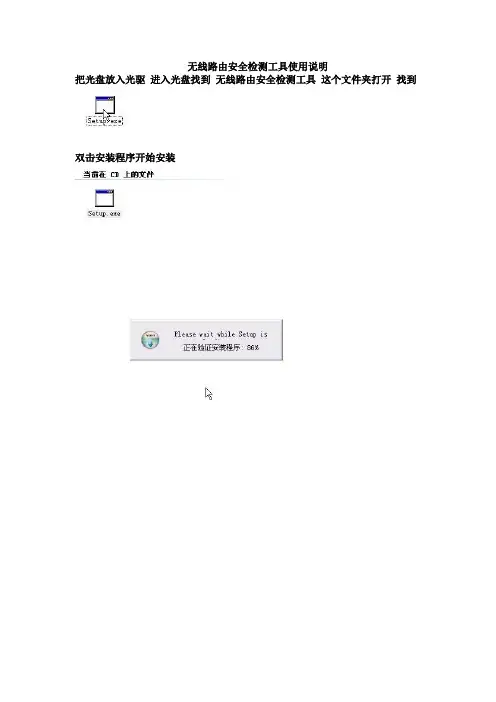
无线路由安全检测工具使用说明把光盘放入光驱进入光盘找到无线路由安全检测工具这个文件夹打开找到双击安装程序开始安装这里改下最好不要安装在C盘点下安装开始安装程序点完成就安装好了桌面就会有这个图标现在把网卡插在电脑的usb接口,可以启动这个软件了。
双击这个图标就开启这个软件了第一次启动这个软件要先创建一个这里点确定启动中…………………………找到网卡这个不要管我们勾住这个网卡就行了的。
这里软件里弹出来没有找到网卡这个不要管我们勾住这个网卡就行了的。
这样就行了现在启动破解软件双击桌面spoonwep 下面的操作和说明书上的操作是完全一样的了我就简单的说下了这里软件里弹出来没有找到网卡这个不要管我们勾住这个网卡就行了的。
NET CARD:表示选择网卡,卡王选择WLAN0;DRIVER;表示选择驱动,卡王选择NORMAL;MODE;表示是否有目标,若是你不知道需要破解哪个无线网络,选择UNKNOWN VICTIM,点下NEXT 搜寻目标CHAN HOPPING:表示全信道扫描,点击,开始扫描。
ESSID 是路由器名称。
破解时最好选DATA数据多的和pow信号强度高的。
这样破解的速度会快很多的若在C LIS已有打勾选项“”,表示该A P 下存在客户端。
这里选择目标A NY,点击来确定目标,进行攻击参数选择界面攻击参数设置及攻击LAUNCH 表示攻击模式的选择,这里提供了4种攻击模式:1) ARP REPLAY ATTACK,表示-3 ARP 注入;(有客户端时选)2)P0841 REPLAY ATTACK,表示-2 交互式注入;(首选)3)CHOPCHOP&FORGEATTACK,表示-4 断续注入;(次次选)4)FRAGMENTATION&FORGE ATTACK,表示-5 碎片注入。
(次选)点击执行破解程序S POONWEP,执行过程成将变为。
破解中破解速度和信号强度还有DATA数据包成正比的时间几分钟到几十分钟不等备注说明:若一种攻击模式没办法获取密码,可跟换其他攻击模式尝试。
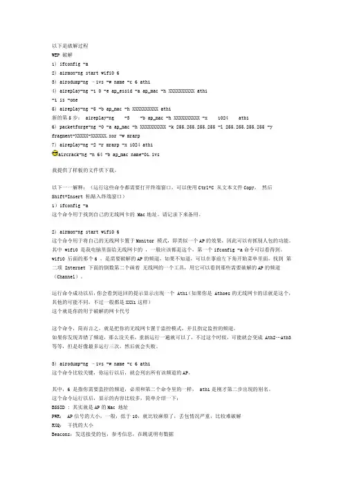
以下是破解过程WEP 破解1) ifconfig -a2) airmon-ng start wifi0 63) airodump-ng –ivs -w name -c 6 ath14) aireplay-ng -1 0 -e ap_essid -a ap_mac -h XXXXXXXXXX ath1-1 is -one5) aireplay-ng -5 -b ap_mac -h XXXXXXXXXX ath1新的第5步: aireplay-ng -3 -b ap_mac -h XXXXXXXXXX -x 1024 ath16) packetforge-ng -0 -a ap_mac -h XXXXXXXXXX -k 255.255.255.255 -l 255.255.255.255 -y fragment-XXXXX-XXXXXX.xor -w mrarp7) aireplay-ng -2 -r mrarp -x 1024 ath1aircrack-ng -n 64 -b ap_mac name-01.ivs我提供了样板的文件供下载。
以下一一解释:(运行这些命令都需要打开终端窗口,可以使用Ctrl+C 从文本文件Copy,然后Shift+Insert 粘贴入终端窗口)1)ifconfig -a这个命令用于找到自己的无线网卡的 Mac地址。
请记录下来备用。
2) airmon-ng start wifi0 6这个命令用于将自己的无线网卡置于Monitor 模式,即类似一个AP的效果,因此可以有抓别人包的功能。
其中 wifi0 是我电脑里面给无线网卡的,一般应该都是这个,第一个ifconfig -a命令可以看得到。
wifi0 后面的那个6 ,是需要破解的AP的频道,如果不知道,可以在事前左下角开始菜单里面,找到第二项 Internet 下面的倒数第二个画着无线网的一个工具,用它可以看到那些需要破解的AP的频道(Channel)。

Kali 配置教程(浮尘:717295376)2014年10月9日 15:29一、系统下载 下载地址:http://www.kali.org/downloads/ Kali Linux 镜象 ISO 文件 Kali Linux 提供了 32 位和 64 位的可引导 ISO 警告!请确认你从官方源下载的 Kali Linux 与官方提供的 MD5 校验码一致。
因为在二次封 装的时候往 Kali Linux 植入恶意代码并通过非官方渠道发布是件很容易的事情。
下载 Kali ISOVMware 镜象 Kali 提供了 32 位和 64 位的预装了 Vmware Tools 的 VMware 虚拟机镜象。
ARM 镜象 由于 ARM 的架构性质,单一的一个镜象不能通用于所有 ARM 设备运行。
我们提供了如下 设备的 Kali Linux ARM 镜象: rk3306 mk/ss808•Raspberry Pi•ODROID-U2/X2•MK802/MK802 II•Samsung Chromebook验证下载的镜象的 MD5 校验码 验证你下载的文件的 MD5 校验码与官方提供的校验码是否一致很重要。
在 Linux 验证 MD5 校验码 md5sum kali-i386。
iso 2455da608852a7308e1d3a4dad34d3ce kali-i386。
iso 在 OSX 验证 MD5 校验码 md5 kali-i386。
iso MD5 (kali-i386。
iso) = 2455da608852a7308e1d3a4dad34d3ce 在 Windows 验证 MD5 校验码 Windows 本身不能计算 MD5 校验码,所以你需要 MD5summer 这类软件来验证 MD5 校验码。
二、系统安装 分为图形安装和文字安装模式,在此不作详述。
三、安装VMware Tools 复制VMware Tools到桌面 进入桌面:cd Desktop/ 解压缩:tar zxpf VMwareTools-*.tar.gz 进入压缩文件夹:cd vmware-tools-distrib/ 安装VMware Tools:./vmware-tools-install.pl 解决VMware下鼠标慢的问题:apt-get install xserver-xorg-input-vmmouse四、更新软件源 修改sources.list文件:leafpad /etc/apt/sources.list #官方源 deb http://http.kali.org/kali kali main non-free contrib deb-src http://http.kali.org/kali kali main non-free contrib deb http://security.kali.org/kali-security kali/updates main contrib non-free #激进源,新手不推荐使用这个软件源 deb http://repo.kali.org/kali kali-bleeding-edge main deb-src http://repo.kali.org/kali kali-bleeding-edge main #中科大kali源 deb http://mirrors.ustc.edu.cn/kali kali main non-free contrib deb-src http://mirrors.ustc.edu.cn/kali kali main non-free contrib deb http://mirrors.ustc.edu.cn/kali-security kali/updates main contrib non-free #阿里云kali源 deb http://mirrors.aliyun.com/kali kali main non-free contrib deb-src http://mirrors.aliyun.com/kali kali main non-free contrib deb http://mirrors.aliyun.com/kali-security kali/updates main contrib non-free 五、系统更新 apt-get update&& apt-get dist-upgrade 六、安装工具 1.安装中文输入法 拼音五笔: apt-get install fcitx-table-wbpy ttf-wqy-microhei ttf-wqy-zenhei 经典的ibus: apt-get install ibus ibus-pinyin fcitx拼音: apt-get install fcitx fcitx-googlepinyin fcitx-pinyin fcitx-module-cloudpinyin 安装完成后使用:im-config进行配置。
全程图解“奶瓶”破解密码实用教程蹭网设备:卡王卡皇……还有台湾信号王用过500G,最近新出的25万N其实就是偷人家网的东东。
我用的是“台湾信号王”实质上是一种大功率无线网卡,同时配备了自动破解软件。
由于是无线接收,接收范围大,能同时在几秒内能搜索到大量的网络,我用的是“台湾信号王”,一般情况下搜索到10-30个网络很普遍,就相当同时装了10-30个宽带网线。
现在网上很多这种玩意,,假货也多。
我买过一次假货,所以建议楼主要细心。
我用的是“台湾信号王”,是我用过中最好的,比卡王卡皇好多了。
通过赠送的BT7软件WEP密码%100破解。
WPA、WPA2、TKIP、AES密码格式通过BT7内置500万组密码有机会破解,只要对方密码在这500万组内就能破解。
破解时间和产品并无直接关系,如果对方在使用网络,有客户端破解约5分钟就出密码了。
如果对方没有使用网络,时间会增长,当然你可以暂时选择其它网络破解。
得,这路由器已经被人蹭上了。
于是重启了路由器,改掉了密码,换上WAP加密,一切又都顺畅了起来。
怎样才能不被蹭?这被人蹭的感觉真不好,那么怎样才能不让人蹭呢?我想还是先来看看如何蹭别人,这样才能从根本上了解这其中的一切奥秘。
UltraISO软件界面下载好的“奶瓶”系统是一个.iso文件,而大小只有40MB左右,因此我们可以轻易的使用镜像软件将其写入U盘。
这里,我们使用了UltraISO这款软件,相比其它的同类型软件,这款显得要简便易懂很多。
导入镜像文件之后,选择写入方式写入速度很快,一分钟不到加载引导文件但是有时候选择直接写入之后,电脑并不能成功从U盘启动“奶瓶”。
因此如果制作不成功之后,我们还需要选择手工加载引导文件。
引导文件位置我们首先需要将下载的“奶瓶”的.iso文件解压缩,然后在如上图所示的目录中找到引导文件,然后再进行加载,如此操作之后,再进行U盘的写入。
当我们用光盘安装Ubuntu时,可能回出现如下错误: Could not find kernel image: linux我们可以用如下方法解决: 1、Make sure that the syslinux.cfg file exists on the USB flash drive. Depending on which version of linux you have installed to your flash drive, the syslinux.cfg file should be found at the root of the drive or within the /boot/syslinux or /syslinux directory 2、If a file named isolinux.cfg exists and syslinux.cfg does not, rename isolinux.cfg to syslinux.cfg 3、If the syslinux.cfg file does exist and your still encountering the error, open the syslinux.cfg file with a text editor and make sure that the paths to your kernel and initrd files are correct.译文: 1、确保U盘中存在syslinux.cfg文件。
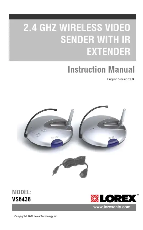
Instruction ManualEnglish Version1.0MODEL:VS6438 Copyright ©2007 Lorex Technology Inc.Explanation of two SymbolsThe lightning flash with arrowhead symbol, within anequilateral triangle, is intended to alert the user to thepresence of uninsulated "dangerous voltage“within theproduct's enclosure that may be of sufficient magnitude toconstitute a risk of electric shock to persons.The exclamation point within an equilateral triangle isintended to alert the user to the presence of importantoperating and maintenance(servicing) instructions inthe literature accompanying the appliance.THE GRAPHIC SYMBOLS WITH SUPPLEMENTAL MARKING ARE ONTHE BOTTOM OF THE SYSTEM.FCC CLASS B NOTICESAFETY INSTRUCTIONS1. HEED WARNINGS -All warnings on the appliance and in the operating instructions should be adhered to.2. FOLLOW INSTRUCTIONS -All operating instructions should befollowed.3. WATER AND MOISTURE -Do not use this video product near water –for example, a bath tub, wash bowl, kitchen sink, laundry tub orswimming pool, or in a wet basement.4. POWER SOURCES -This product should be operated only from the typeof power source indicated on the marking label.5. OVERLOADING -Do not overload outlets and extension cords, whichcan result in a risk of fire or electric shock.6. SERVICING -Do not attempt to service this product yourself. Opening orremoving covers may expose you to dangerous voltage or other hazards.Refer all servicing or repairs to qualified service personnel.7. DAMAGE REQUIRING SERVICE -Unplug this product from the walloutlet and refer servicing or repairs to qualified service personnel under the following conditions:a. When the power supply cord or plug is damaged.b. If liquid has been spilled or objects have fallen into the product.c. If the product has been exposed to rain or water.d. If the product does not operate normally by following the operatinginstructions. Adjust only those controls that are covered by theoperating instructions.e. If the product has been dropped or the cabinet has been damaged.f. When the product exhibits a distinct change in performance.8. REPLACEMENT PARTS -When replacement parts are required, besure the service technician has used replacement parts that arespecified by the manufacturer or have the same characteristics as the original part. Unauthorized substitutions may result in fire, electricshock, or other hazards.9. SAFETY CHECK -Upon completion of any service or repairs to thisvideo product, ask the service technician to perform safety checks to determine if the video product is in proper operating condition.10. An appliance and cart combination should be moved with care.Do not place this equipment on an unstable cart, stand, or table.Theequipment may fall, causing serious injury to a child or adult, andserious damage to the equipment. Wall or shelf mounting shouldfollow the manufacturer's instructions and should be done witha mounting kit approved by the manufacturer.TABLE OF CONTENTS PAGEINTRODUCTION & FEATURES………………………………………SYSTEM INCLUDES………………………………………………….. CONTROLS AND FUNCTIONSWireless Transmitter…................….……………………..……...Wireless Receiver...……..............................……….……...……INSTALLATION OF WIRELESS TRANSMITTER…………………. INSTALLATION OF WIRELESS RECEIVEROperation with TV (Using RCA Cables)......……………….…....Operation with TV (Using Coaxial Cable) ..............…..……......Operation with TV and VCR………………………………………SYSTEM OPERATIONMultiple Devices ……………………………………………………Using the IR Extender feature with your Remote Control………How to use the IR Extender Accessory………………………….. TROUBLE SHOOTING ..............................................………..…... TECHNICAL SPECIFICATIONS .................................................... CARE & MAINTENANCE……………………………..……………….1 2 3 4 56 7 8 9 9 1011 12 13•Send signal to a second TV Satellite, DVD, or Security Camera •Change TV Functions from remote location using remote control extender •View video from another room•300 ft Wireless Transmission (open space)•2.4 GHz Wireless Transmission•Crystal clear Video and Stereo audio•4 Channel Wireless SystemSYSTEM INCLUDES:1 - 2.4 GHz Wireless Receiver 1 - 2.4 GHz Wireless TransmitterOwner’s Manual Also includes:2-9V DC 500mA Adapters 2 –RCA Audio/Video Cables 1 –Coaxial Cable1 -Remote Control IR ExtenderREAR VIEW9BOTTOM VIEWWIRELESS TRANSMITTER..Location of Transmitter controls 1. Channel Selector Button –Used to select between channels 1-42. LED Channel Indicators –Indicator light shows selected channel3. IR Antenna -Extends the effect range between the receiver and the transmitter for the remote control feature4. 2.4 GHz Antenna –High gain dipole antenna transmits audio and video signal to the wireless receiver5. DC IN Jack –Power source for the transmitter6. Video Input Jack (Yellow) –RCA jack for video input connector7. Audio Input Jacks L (White) & R (Red) –RCA jacks for audio input connector8. IR Extender Input –Connection for the IR Extender accessory9. ON/OFF Power Switch –Ensure this switch is set to OFF before plugging the system into an electrical outletTOP VIEW 12345678CONTROLS & FUNCTIONSWIRELESS RECEIVERREAR VIEW BOTTOM VIEW9105678Location of Receiver controls1. Channel Selector Button –Used to manually switch channels from 1-42. LED Channel Indicators –Indicator light shows selected channel3. IR Antenna -Extends the effect range between the receiver and the transmitter for the remote control feature4. 2.4 GHz Antenna –High gain dipole antenna receives audio and video signal from the wireless transmitter5. Video Output Jack (Yellow) –RCA jack for video output connector (when using RCA connector)6. Audio Output Jacks L (White) & R (Red) –RCA jacks for audio output connector (when using RCA connector)7. RF Out Jack (To TV) –Connect the receiver to a TV using the supplied coaxial cable . (alternative to RCA cable connection)8. DC IN Jack –Power source for the receiver9. ON/OFF Power Switch –Ensure this switch is set to OFF before plugging the system into an electrical outlet10.Channel 3/4 Selector Switch –Used to view picture on television when using coaxial cable (preset to channel 3)CONTROLS & FUNCTIONS4CONNECTING A TRANSMITTER SIGNAL FROM YOUR VCR/SATELLITE/DVD INSTALLATION OF TRANSMITTER1. Connect one end of the RCA cables to the Audio/Video Input jacks of the Transmitter; the other end to the Audio/Video Out jacks of theVCR/Satellite/DVD. Ensure that the yellow, red and white plugs match the yellow, red and white jacks on both the VCR/Satellite/DVD and the Transmitter.2. Plug one end of the supplied power adapter (9V 500 mA adapter) into the back of the transmitter; the other end into an electrical outlet. The system is defaulted to channel 1.Rear ofVCRBack of Transmitter STEP 1:CONNECTING A RECEIVER TO A REMOTE TV THROUGH A VCR INSTALLATION OF RECEIVERSTEP 2:1. Place the wireless receiver near your television (or monitor).2. Connect one end of the RCA cables to the Audio/Video output jacks at the back of the Receiver. Plug the other end of RCA cables into theAudio/Video In jacks on your television. Be sure the yellow, red and white plugs match the yellow, red and white jacks on both the receiver and TV.3. Connect one end of the supplied 9V 500 mA AC adapter into the DC IN jack at the rear of the receiver; the other end into an electrical outlet. Turn the receiver ON. The system is defaulted to channel 1.4. Turn your T.V. to AX (Aux. Mode or TV/Video) to view the picture on your second T.V.5. Adjust the antenna on both the transmitter and receiver as necessary for optimum viewing.You have two options to connect the Receiver: A) Using RCA Cables(see below), or B) Coaxial Cables, please refer to page 7 of this manual.Back of Receiver TelevisionA)CONNECTING A RECEIVER TO A T.V. USING COAXIAL CABLESB)Back of ReceiverTelevision1. Place the wireless receiver near your television (or monitor).2. Connect one end of the coaxial cable to the back of the Receiver. Plug the other end of the coaxial cable to the television.3. Connect one end of the supplied 9V 500 mA AC adapter into the DC IN jack at the back of the receiver; the other end into an electrical outlet. Turn the receiver ON. The system is defaulted to channel 1.4. Search channels 1 through 4 by using Channel Selector Switch on the Receiver and Transmitter.5. Turn your T.V. to channel 3 to view the picture from your second T.V.6. Adjust the antenna on both the transmitter and receiver as necessary for optimum viewing.Audio VideoCONNECTING A RECEIVER TO A REMOTE TV THROUGH A VCR Rear of VCRAudio VideoRCA Cable (Supplied)RCA Cable(Not supplied)TelevisionBack of Receiver Electrical OutletEnsure the Power Switch on the Receiver is turned OFF beforeproceeding with the following steps.NOTE 1. Connect one end of the RCA cables to the Audio/Video output jacks located at the rear of the Receiver. Plug the other end of the RCA cables into the Audio/Video In jacks on your VCR.2. Connect one end of other RCA cables to the Audio/Video jacks on your Television. Plug the other end of the RCA cables into the Audio/Video Out jacks on your VCR.3. Turn both the Transmitter and Receiver ‘ON’. Set your TV to Video mode to view the signal from the T.V. (Consult your televisions owners manual on setting the Television to Video (Aux) mode.4. Turn your T.V. to AX (Aux. Mode) to view the picture on your second T.V.5. Adjust the antenna direction on both the transmitter and receiver as necessary for optimum viewing.For optimum viewing reception you may need to change thechannels of your transmitter and receiver to the same channelsbetween CH 1 –CH 4.NOTECONNECTING MORE VIDEO DEVICES TO YOUR SYSTEM (MAX. OF 4) The Video Sender system allows you to connect more than 1 transmitter and receiver. Connecting more than one transmitter to the system is normally utilized when viewing multiple Video Security Cameras on a television or monitor. You also have the option to connect multiple receivers to this system for viewing your Satellite/DVD picture from multiple rooms.When connecting additional transmitters to this system, ensure the transmitter is set to a different channel. Use the Channel Select button to navigate between different channels.USING THE IR EXTENDER FEATURE WITH YOUR REMOTE CONTROL The system not only allows you to send crisp audio/video from one area to another, it also gives you the ability to control the source using your existing remote control device. It converts the infrared (IR) signal emitted by your remote control to a radio frequency (RF) signal in the UHF band at the receiver and sends it back to the transmitter where the RF signal is converted back to the original IR signal and beamed to the audio/video device.The following states the use of the remote control feature to control you’re A/V equipment by using the existing remote control:Simply connect the IR extender plug into the back of the transmitterand position the IR Extender near the A/V source equipments frontpanel.Sometimes it may be difficult or even impossible to orient the transmitter unit such that it can be “seen”(face-to-face) with the A/V equipment you wish to control. (This happens when the surface is not adequate for this,or you wish to remotely control the A/V equipment in different locations without re-orienting the transmitter). In this case, using the extender willbe more convenient.HOW TO USE THE IR EXTENDER ACCESSORY The IR Extender connects to the transmitter through its own specialconnector plug. The extender emits an IR signal to your A/V device with the remote signal. To use the IR extender, follow the instructions below;1. Plug the IR Extender into the back of the transmitter (see page 3)2. Orient the end of the IR Extender so that it points in the generaldirection of the IR sensors on the source device that you wish tocontrol 3. Position the receiver so that your remote control signal can strikethe IR window on the front of the unit. To use your remote control,point it at the front of the receiver.TransmitterIR Extender InputReceiverUHFIR ExtenderFOR MORE INFORMATION, VISIT OUR WEBSITE AT:TROUBLESHOOTINGIf the system does not function properly, check the following pointsbefore contacting the service center.Causes & RemediesProblemsVideo Source Receiver/Transmitter No power(no picture/sound)-Video source/ device not connected to transmitter-AC adapter not plugged in-Power switch not turnedON-AC adapter not plugged in -Power switch not turned on -TV or Monitor not turned on -Improper A/V or coaxial cable connection Poor Reception -Video source/device notconnected to transmitter-AC adapter not plugged in-Power switch not turnedON-Adjust antenna direction -Improper channel 1-4selection Picture flickering Picture too bright or too dark -Strong spot light in thefield of view-Lighting source in thefield of view-Adjust brightness control on TV/monitor Picture rolls andjumps orscrambled picture -Adjust antenna direction -Adjust antenna directionTECHNICAL SPECIFICATIONSWIRELESS TRANSMITTERBecause our product is subject to continuous improvement, SVC reserves the right to modify product designs and specifications without notice and without incurring any obligation. E&OEPower supplyCurrent consumptionChannel frequencyChannel selectionModulation systemVideo channelVideo input levelAudio channelAudio input levelAntenna typeLED indicatorIR Control DistanceIR Transmission AngleDimensionsWeight AC adapter 9V DC 500mA output 150 mA TYP.2.411 –2.473 GHz 4 channel FM modulation 11 Vpp @ 75 Ohm 11 Vpp @ 600 Ohm Dipole Power > 3 meters 30 degrees 5.25”(Diameter) x 1.5”(Height)136 grams or 4.8 OzWIRELESS RECEIVERReceiving frequencyOutput levelSensitivityAntennaIR Receiver DistanceIR Receiver AngleOperating temperaturePower sourceDimensionsWeight 2.411GHz -2.473GHz (4CH)1.0Vp-p(Video), 3.0Vp-p(Audio)> 85 dBm Dipole antenna 3 meters 45 degrees -14ºto + 122ºF or (-10ºC to + 50 ºC)9V 500mA DC Adapter 5.25”(Diameter) x 1.5”(Height)181 grams or 6.4 OzCARE AND MAINTENANCE:Please follow these instructions to ensure proper care and maintenance of this systemKeep your monitor and camera dry. If it gets wet, wipe it dry immediately.Use and store your unit in normal temperatureenvironment. Extreme temperatures can shorten the life of the electronic devices.Handle the monitor carefully. Dropping it can cause serious damage to the unit.Occasionally clean the unit with a damp cloth to keep it looking new. Do not use harsh chemicals, cleaning solvents or strong detergents to clean the unit.Keep the unit away from excessive dirt and dust. It can cause premature wear of parts.It’s all on the webProduct InformationUser Manuals Quick Start Guides Specification Sheets Software Upgrades Firmware Upgrades Lorex Technology I nc.VISITwww 。

电信“我的e家”无线猫路由上网破解全教程中国电信出了一个“我的E家”上网套餐,实际上这个无线猫功能并不完整,至少ADSL Modem是不完整的。
这是个被阉割了的无线Modem!电信甚至屏蔽了这个Modem里面几乎所有的高级功能:NAT,upnp……请注意:电信在大部分情况下只是“屏蔽”,而不是真正意义上的“阉割”。
那么我们还可以恢复这些被阉割的功能。
道理很简单,思路就两条:A、通过对无线猫内置的配置程序的修改,隐藏了部分菜单选项,或部分菜单为灰色不可选。
如果我们能找到该选项的隐藏地址,一般都能够开启该功能。
若能直接改配置恢复,那就直接把配置改回来(常见于早期的宽带猫);B、若配置功能都找不到,也就是说该配置文件自出厂时已被修改,那么就只有刷厂方相同型号的非电信“我的E家”配套软硬件,也就是我们常说的FirmWare!下面就谈一谈常见的几种无线猫的破解:一、“我的E家”HG520s无线猫的破解若你的宽带猫是华为的HG520S,遵从以下步骤:1、登录192.168.1.1,输入用户名admin,密码admin;2、然后保留已登录的IE窗口,新开IE输入地址打开被隐藏了的路由NAT配置页面:http://192.168.1.1/phtml/nat/nat.html将NAT选项点击“允许”(电信默认设置为‘桥接’);3、如果通道有内容(如8/35)的一定要先删除,然后在pppoe设置的页面设置为8/35(常州的VCI/VPI值,其它地区的参数请自行在网上查询);4、保留已开的IE,新开IE输入地址打开被隐藏的PPOE拨号界面:http://192.168.1.1/phtml/mpvc/add_pppoe.html填入你的宽带帐号与密码;5、返回原始界面保存退出。
6、在客户端电脑的tcp/Ip中设网关为路由器地址192.168.1.1,即可多台机器同时上网了,意味着我的e家路由功能成功开启(含无线ap)。
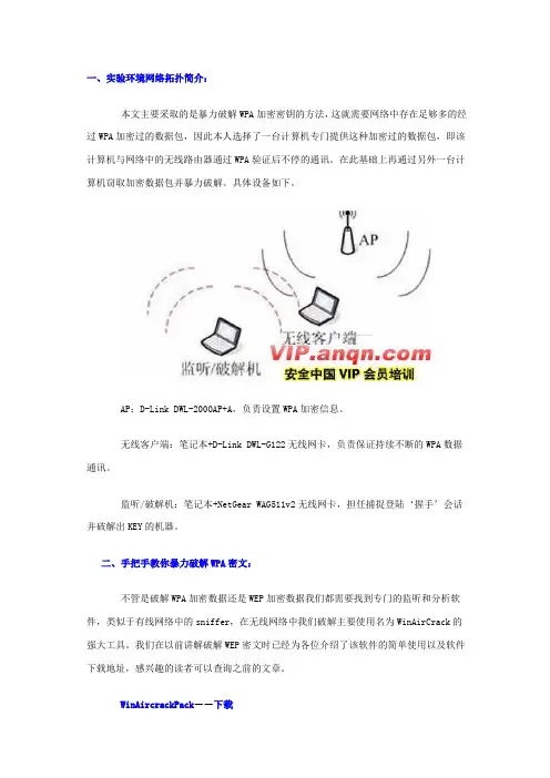
一、实验环境网络拓扑简介:本文主要采取的是暴力破解WPA加密密钥的方法,这就需要网络中存在足够多的经过WPA加密过的数据包,因此本人选择了一台计算机专门提供这种加密过的数据包,即该计算机与网络中的无线路由器通过WPA验证后不停的通讯。
在此基础上再通过另外一台计算机窃取加密数据包并暴力破解。
具体设备如下。
AP:D-Link DWL-2000AP+A,负责设置WPA加密信息。
无线客户端:笔记本+D-Link DWL-G122无线网卡,负责保证持续不断的WPA数据通讯。
监听/破解机:笔记本+NetGear WAG511v2无线网卡,担任捕捉登陆‘握手’会话并破解出KEY的机器。
二、手把手教你暴力破解WPA密文:不管是破解WPA加密数据还是WEP加密数据我们都需要找到专门的监听和分析软件,类似于有线网络中的sniffer,在无线网络中我们破解主要使用名为WinAirCrack的强大工具。
我们在以前讲解破解WEP密文时已经为各位介绍了该软件的简单使用以及软件下载地址,感兴趣的读者可以查询之前的文章。
WinAircrackPack--下载第一步:下载WinAirCrack程序并解压缩,然后根据之前的文章下载自己无线网卡对应的驱动,将驱动升级为基于atheros芯片的无线网卡。
具体方法需要我们到/support/downloads/drivers这个地址下载适合自己无线网卡品牌的驱动。
第二步:无线网卡准备工作完毕后打开WinAirCrack程序安装主目录,运行其中的airdump.exe。
第三步:首先选择监听网卡为自己的无线网卡,接下来选择自己无线网卡使用的芯片类型,“o”是hermesl/realtek,“a”是aironet/atheros,只有这两类。
由于笔者的是以atheros为核心的产品,所以选择a即可。
第四步:选择要监听的信号,由于笔者知道无线网络使用的是10信道,所以直接选择10。
如果日后各位读者要破解WPA又不知道其发射信道的话,可以选择0,这代表扫描所有信道。
路由器限速p2p终结者家庭使用简单方法路由器限速(p2p终结者)家庭使用简单版p2p终结者是一款局域网控制软件,他的主要功能就是控制和限制同一个局域网内其它的上网用户,对家庭来说也可以,如本人在玩网络游戏,儿子在旁边下载,搞的我很慢慢,p2p终结者就能很好的对付这一点,说简单点就是合理的分配家里的宽带网速。
如家里的2M宽带,通过合理分配可以做到。
网上有很多限制下载的软件,个人觉得最好的还是P2P终结者话不多说,直接上图。
“P2P终结者”是黑客软件,在使用前,请关闭你本地电脑的防火墙,包括ARP防火墙。
对于360来说就是360杀毒—设置—实施防护—局域网防护(关掉),对于要限速的电脑也要关闭局域网防护,否则360很容易的拦截你的限速。
第一步就是安装软件,安装完成后启动软件。
对于目前来说是 4.22版本的为多数。
第二步就是要设置。
点击选项选项—高级选项—网路环境设置,家庭选择第二个,网卡一般只有一个。
然后就是控制选项和常规设置以及软件界面设置接下来就是点击——选项——时间计划了新建,输入一个名字,我的是限速,在下面的周一到周六用鼠标拖拽全部选上。
确定。
这就是一个时间计划名称了。
接下来点击选项—控制规则设置新建一个规则,自己取名,我的取名是全天限速,下面选中我们上面设置的时间计划,我的是限速这个计划。
下一步,选择上行和下行的数量,一般家庭的宽带,可以把要限速的设置为上行50-100,下行70-120,个人就是这样设置的。
然后下一步就是几个限制,当然实在家里,我都没有选中。
接下来就是点击扫描网络,有时候进去是自动扫描网络。
找到需要的限速的电脑为他选中规则,我的是限速规则。
如果不知道是哪台,就把其他的网线拔了,再插上就知道了。
或者右键点击网上邻居,本地连接右键状态,点支持—详细信息看到实际地址也能知道,然后点击主界面左上方的启动控制就OK了。
不用python破解wifi密码的方法【实用版3篇】篇1 目录1.引言:介绍 WiFi 密码破解的重要性2.方法一:使用 Wireshark 工具3.方法二:使用 Aircrack-ng 工具4.方法三:使用 Reaver 工具5.方法四:使用 John the Ripper 工具6.总结:各种方法的优缺点和适用场景篇1正文在当今数字化时代,WiFi 已成为日常生活中不可或缺的一部分。
然而,对于许多用户来说,WiFi 密码的安全性一直是一个令人担忧的问题。
为了保障个人网络安全,了解如何破解 WiFi 密码变得至关重要。
本文将为您介绍四种不用 Python 即可破解 WiFi 密码的方法。
方法一:使用 Wireshark 工具Wireshark 是一款功能强大的网络协议分析器,可捕获并分析网络数据包。
用户可以通过 Wireshark 捕获 WiFi 信号,然后分析数据包以获取 WiFi 密码。
方法二:使用 Aircrack-ng 工具Aircrack-ng 是一款开源的 WiFi 安全工具,可用于破解 WEP 和WPA/WPA2 密码。
使用该工具,用户可以利用已知的用户名和密码尝试登录 WiFi 网络,并在成功登录后获取 WiFi 密码。
方法三:使用 Reaver 工具Reaver 是一款专门用于攻击 WiFi 网络的工具,可通过不断尝试密码来破解 WiFi 密码。
该工具支持多种攻击方式,如暴力破解、字典攻击等,可根据实际情况选择合适的攻击方式。
方法四:使用 John the Ripper 工具John the Ripper 是一款强大的密码破解工具,支持多种加密算法,包括 WiFi 密码。
用户可以利用该工具对已捕获的 WiFi 数据包进行破解,从而获取 WiFi 密码。
总结:以上四种方法各有优缺点和适用场景。
Wireshark 和 John the Ripper 适合对网络协议和密码算法有一定了解的用户;而 Aircrack-ng 和 Reaver 则更适合初学者。
郑州吉瑞特电子科技有限公司快速操作手册<V1.01> ◎吉瑞特电子.版权所有User Manal编写人:吴楠Version:V1.01审批人: Date:2014/3/19版本变更记录日期版本作者/修改者描述审核人2014/3/14 V1.0 吴楠创建2014/3/19 V1.01 吴楠添加WIFI快速操作项目录1. 接口简介 (4)2. 设备连接 (5)3. 局域网内IE观看 (6)4. 客户管理观看 (8)5. 无线(wifi)设置 (10)首先感谢您选购吉瑞特网络摄像机。
本公司研发生产的网络摄像机具有稳定性强,操作简单,功能强大等特点,产品通过CE,FCC及公安部检测认证。
有关产品的详细说明请参阅产品包装盒内配套光盘上的《产品使用说明》。
1. 接口简介(接口一)DC5V:直流电源接口,5V直流电源输入,电源用错会造成摄像机的水久损坏。
I/O Alarm:1:报警输入、输出接口,开关量输入。
常开常闭可以在客户端中配置,默认为常开输入。
2/3:地。
4:报警输出,开关量输出,用于报警时联动输出。
AUDIO:音频,音频线性输出,可外接带功放喇叭进行对讲。
ANT:WIFI或3G产品天线接口。
T/F和USB:可插入TF卡或U盘,做为产品的内置存储。
(接口二)红色:12V直流电源接口,我们建议使用优质的开关电源,12V2A。
黑色:RJ45接口,10/100自适应以太网口,2. 设备连接如图所示,用网线将摄像机连接交换机/路由器/HUB或直接与电脑相连,用电源给设备供电,等待1分钟左右,摄像机启动完成。
电脑要与摄像机通信,首先确认电脑的IP是否与摄像机IP段一致,电脑查看IP方法:1.网上邻居》属性》本地连接》详细信息,如图1所示2.开始》运行,输入“CMD”命令进入命令提示符窗口,输入“ipconfig”+回车即可查看电脑IP。
如图2所示(图1)(图2)3. 局域网内IE观看1. 摄像机内置web服务器,可直接通过IE进行访问,摄像机默认IP为:http://192.168.1.102. 首次IE浏览时需下载并安装控件,通常IE缺省的安全设置禁止用户下载和运行控件,因此要修改IE的安全设置,在IE浏览器菜单栏中找到“工具”-->“Internet选项”进入Internet选项-->安全-->自定义级别在安全设置里把有关ActiveX控件和插件全部启用,确认5. 打开IE浏览器,输入网址:http://192.168.1.10,输入用户名admin,密码为空,登入后即可对摄像机进行观看和管理。
wifirepeater的连接方法嘿,朋友们!今天咱来聊聊那个超实用的 Wi-Fi Repeater 的连接方法。
这玩意儿就像是给咱的 Wi-Fi 信号加了一双翅膀,能让信号飞得更远更广呢!首先呢,你得找到那个 Wi-Fi Repeater,就像找到你心爱的宝贝一样。
然后把它找个合适的地儿放好,可别随便乱丢哦,不然它怎么好好工作呀!接下来,就是关键步骤啦!打开你的设备,找到 Wi-Fi 设置,就像你找朋友聊天一样自然。
在那里面,你得找到 Wi-Fi Repeater 发出的信号,一般它会有个特别的名字,就像每个人都有自己独特的外号一样。
当你找到它了,别犹豫,赶紧点击连接呀!这时候可能会让你输入密码,就跟进家门要钥匙一样,可别输错啦!连接上之后,你就会发现,哇塞,原来信号不好的地方现在也满格啦!是不是感觉超棒的?就好像原本昏暗的房间突然被阳光照亮了一样。
你想想看,以前在那个角落刷手机老是卡顿,现在呢,顺畅得很,这感觉多爽呀!要是你连接的时候遇到点小问题,别着急上火呀,就像走路偶尔会绊一下脚一样,很正常的嘛。
再仔细检查检查步骤,看看是不是哪里没弄对。
比如说,密码是不是输错啦?位置放得好不好呀?多试试,总会成功的嘛!咱再想想,这 Wi-Fi Repeater 就像是个信号小天使,默默在那里为我们服务呢。
它让我们在家里的每个角落都能愉快地上网,看视频、玩游戏,多开心呀!所以呀,学会这个连接方法多重要呀!以后再也不用担心信号不好啦,走到哪儿都能享受快速的网络。
还等什么呢,赶紧去试试吧,让你的 Wi-Fi 信号变得超级强大!就这么简单的几步,就能让你的网络生活变得更加美好,何乐而不为呢?相信我,你一定会爱上这种感觉的!。
极玩加速平台支持多条加速线路,路由器上一键连接。
官方极路由刷极玩固件方法
1、电脑连接极路由,浏览器打开:默认密码是 admin
2.点击云插件
3.点击路由器信息
4. 点击高级设置进行开发者模式申请。
申请开发者模式会失去保修,需要手机微信添加极路由微信号,然后申请绑定极路由,按步骤提示操作即可;
5.申请完毕后回到全部插件,安装开发者模式;
6.点击免费安装,耐心等待重启完成;
7 路由器重启完成后,在电脑上解压下载的压缩包的文件;
8.先打开程序;
9.直接点击登录,如果你后台密码修改了的话点击root下的编辑来修改密码,如果提示任何错误直接按确定即可!
10. 点击右侧的...,找到tmp文件夹双击进入;
重命名固件名字为
12、打开文件夹中的程序;
要确定您的端口是填写的1022
弹出确认窗口,选“是”
打开黑色窗口后,输入小写 root,回车,然后是路由器密码,默认的是admin(输入时不会显示,盲打),回车;
就是极路由的固件注意-F要大写 !!
路由器开始刷机,此时路由器指示灯会跑马灯似的依次闪烁!
等待4分钟,千万不能断电,然后尝试进入
如果无法进入,尝试复位:上电情况下,用牙签捅住后面板RST孔10秒,松开,等待重启。
GerixWifi Cracker是另一个aircrack图形用户界面,用来方便快速测试wep/wpa.
下面是对wep/open简单说明.更多功能自已慢慢去发掘了!
目前该软件已加入bt的官方源.安装很简单.
apt-get update
apt-get install gerix-wifi-cracker
1.运行gerix-wifi-cracker
菜单 >BackTrack> Radio Network Analysis > 80211 > ALL >GerixWifi Cracker
2.选择 information gathering > card configuration
设置如图
3.选择 monitor mode control
点击put your card in monitor mode
4.点击 start the wireless network mapping
得到ap详细信息
5. 选择 save information
设置如图
6. 选择 wep
选择一种攻击模式,如我使用的是arp重播. 点击 start sniffing and logging捕获数据包
7. 点击 associate with ap use fake auth
做虚假认证
8.成功后点击 arp request replay
arp重播
9 成功后选择 cracking
点击 aircrack-ng -decrypt wep password 等上N分钟得到key。