JULABO加热制冷恒温循环器F38-EH中文操作说明书
- 格式:pdf
- 大小:557.30 KB
- 文档页数:27
一周编程电子智能室内温控器LOGIC 578001使用指南引言感谢您选择了我们的产品及对我们的信任与支持。
本装置是电子式定时恒温器,可设置一星期为周期的运行程序。
通过该装置,可对安装环境内的温度进行十分精确的调节控制,满足用户对创造一个舒适生活环境的要求。
符合标准:符合欧盟法令:EN 60730-1 标准及其修订内容欧盟 B.T.73/23/EEC号法令EN 60730-2-7 标准欧盟 E.M.C.89/336/EEC号法令及93/68/EEC修改法令EN 60730-2-9 标准产品规格:电源:二节LR6型1.5V碱性电池温度调节范围:10至35℃显示屏显示之环境温度:0至40℃(分辩率0.1℃)温度修正频率:每分钟一次微分:0.2至0.4K探针传感器:NTC3%保护等级:IP20绝缘等级:热梯度:1K/15分输出:转换继电器触点容量:8(2.5)A250V~作用类型:1BU绝缘条件:正常环境最大工作温度:50℃储存温度:0-60℃防冻温度:6℃恒定运行程序:以一星期为周期设置软件等级:A液晶显示屏夏季/冬季(采暖/空调)切换程序设置中的最小增减允许时间:1小时安装:壁式安装安装及连接:安全预防措施在进行定时恒温器的连接之前,请确认受其控制的设备系统(采暖锅炉、泵和空调系统等)电源已断开,并需检查这些设备的使用电压是否与定时恒温器底座上表明的电压相符(最大250V~).(图4)安装位置定时恒温器须安装在远离热源(暖气装置、阳光、厨房)和门窗之处,安装高度离地面约1.5米。
(图5)安装见图6-7-8电气连接将受定时恒温器控制的设备系统电线与定时恒温器的1号及2号接线柱连接见接线图10所示U=受定时恒温器控制的设备1=共用接线柱2=常开接线柱3=常闭接线柱重要事项:请务必严格遵照相关现行法律的规定及安全规范安装定时恒温器。
电池更换:当在显示屏上闪烁显示“”标志时,定时恒温器还可正常工作约一个月左右,然后将会停止工作并固定显示“”。
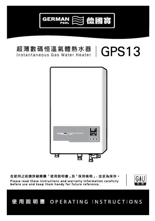
超薄數碼恒溫氣體熱水器I n s t a n t a n e o u s G a s Wa t e r H e a t e r內容Content請確定遵從Please make sure to follow如何操作How to Operate當有需要時請查看Please read when necessary安全操作注意事項 ........................................................ 2Cautions for safety operations第一次使用熱水器 ..................................................... 10To operate the heater for the first time使用熱水器方法 .......................................................... 11Operating Instructions日常檢查及保養 .......................................................... 13Daily inspection and maintenance熱水器修理指南 .......................................................... 15Trouble shooting of the heater規格 ............................................................................... 17Specifications維修服務 ...................................................................... 18Repair service各部份名稱 ..................................................................... 9Parts identifications適用於香港根據香港法例第51章(氣體安全氣體裝置技工及氣體工程承辦商註冊)規例規定,任何人如非註冊氣體裝置技工而安裝/接駁或修理這件氣體爐具即屬違法。
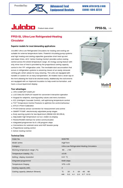
Product data sheet1/3FP55-SLFP55-SL Ultra-Low Refrigerated-Heating CirculatorSuperior models for most demanding applicationsJULABO Ultra-Low Refrigerated Circulators for heating and cooling are suitable for external temperature tasks. Powerful circulating pump systems and high heating and cooling capacities guarantee short heat-up and cool-down times. ACC ‘Active Cooling Control‘ provides active coolingcontrol across the whole temperature range. An energy saving feature with only minor loss of heat is provided by the proportional cooling capacity control in the ‘FP’ refrigeration units. The inevitable dust accumulation that occurs in refrigeration systems is solved by means of an easily removed venting grill, which allows for easy cleaning. The units are equipped with handles or castors for an easy transportation. All models have a drain tap on the front allowing the fluid to be drained easily. Additionally the instruments are equipped with an improved insulation to help avoid ice-formation, and have a visual liquid level display.Your advantagesVFD COMFORT DISPLAYLCD DIALOG DISPLAY backlit for convenient interactive operation Keypad for setpoints, warning/safety values and menu functionsICC (Intelligent Cascade Control), self-optimizing temperature control TCF Temperature Control Features to optimize the control behaviour ATC3 3-Point-CalibrationPt100 External sensor connection for measurement and control SMART PUMP, electronically adjustable pump stagesEarly warning system for low liquid level (DBGM 203 06 059.8)Adjustable high temperature cut-out, visible via display RS232/RS485 interface for online communication Integrated programmer for 6 x 60 program stepsConnections for solenoid valve and HSP booster pump Proportional cooling control Active Cooling Control Technical Data Order No.9352755Model series HighTechCategoryUltra-Low Refrigerated-Heating Circulators Working temperature range (°C)-60 ... +100Temperature stability (°C)±0.05Setting / display resolution 0.01 °C Integrated programmer 6x60 steps Temperature Display VFD, LCD Heating capacity (kW)3Cooling capacity (Medium Ethanol)°C 200-20-40-60kW5.24.12.20.70.13Pump capacity flow rate (l/min)22-26Pump capacity flow pressure (psi) 5.8-10.2Pump capacity flow suction (psi)2.9-5.8Bath opening / bath depth (W x L / D inch)Ø = 2.7 / 9.1Pump connectionsM16x1Barbed fittings diameter (inner dia. / mm)8 / 12Filling volume liters 27RefrigerantR404A External Pt100 sensor connection integrated Digital interface RS232, RS485Optional: Profibus Ambient temperature 5...40 °CDimensions W x L x H (inch)33.5 x 29.9 x 45.7Weight (LBS)400Classification according to DIN12876-1Classification III (FL)Included with each unit 2 each barbed fittings for tubing 8 and 12 mm inner dia.(pump connections M16x1 female).Cooling of compressor AirPower requirement V / Hz / A 3x 260/60/28Available voltage versions400 V / 3 Ph. / 50 Hz 230 V / 3 Ph. / 60 HzCharacteristicsDisplayA perfect viewAmple, easy to read VFD Comfort display for simultaneous display of 3values, warning functions, high temperature cut-off, pump stages(resolution 0.01 °C)Additional plain text information Comfortable LCD dialog display for interactive operation with plain textdisplayPump stage and liquid levelBacklit indicator for selected pump stages and filling volume on Presto®PLUS, Magnum 91 & Forte HTOperationComfortable and detailedComfortable keypad with additional menu functions for pump stages,calibration, control parameters,programmer, warnings, etc.Temperature ControlFor perfect results‘I ntelligent C ascade C ontrol’,automatic & self optimizing adjustment of PID controlparameters, temperature stability ±0.005 °C internal, <±0.05 °CexternalFull control‘T emperature C ontrol F eatures’ for individual optimization, access to all important control parameters,additional settings for band limit,limits, Co-Speedfactor etc.Highest measuring accuracy ‘A bsolute T emperature C alibration’for manual compensation of a temperature difference, 3-point calibrationRefrigeration TechnologyEnergy saving coolingProportional cooling control for automatic adjustment of cooling power or temporary switch-off of compressor as needed to save up to 90 % energy in comparison tounregulated cooling machinesConsistent cooling capacity Easily removable venting grid forquick and easy cleaning100 % Cooling capacity‘A ctive C ooling C ontrol’ for cooling available throughout the entire working temperature range, fast cool-down even at higher temperaturesCondensation and ice protection A heated cover plate prevents condensation or ice build-up in the bathTechnical FeaturesClever pump systemReliable and consistent pump capacity, electronically adjustablepump stagesControl from the external applicationExternal Pt100 sensor connection for precise measurement and control directly in the externalapplicationConnection compliant to standard RS232/RS485 dual-interface forserial data transmission according to EIA-485 industry standard (2-wire bus technology), upgradable withProfibus DPOptimal program control For the execution of time andtemperature dependant profiles, 6temperature profiles with 60 stepsmax., with real time clockAutomatic control of operating timeElectronic countdown-timer function for timer-programmed unitshut-down, standby mode after programmed time expiresWarning & Safety FunctionsEarly warning system for low liquid levelMaximum safety for applications,optical and audible alarm, allows user to refill bath fluid before the unitshuts downEarly warning system for high/low temperature limitsMaximum safety for applications,optical and audible alarm,convertible to automated cut-offfunctionEnhanced protective functions Maximum safety, adjustable high temperature cut-off or dry-running protection, additional display of setpoints permits easy and preciseadjustmentsFor flammable bath fluidsClassification III (FL) according to DIN 12876-1Refer to for more information regarding the entire JULABO product portfolio.Technical changes without prior notification. Images may deviate from the original.。
恒温水浴锅使用说明时间:2009-04-06 07:39:48 来源:作者:电热恒温水浴锅使用操作规程•水箱中加入适量水(最好选用蒸馏水),水位高于隔板50mm 以上,否则电热管将被烧坏。
•接通电源,有接地保护,开启电源开关,绿灯亮,黄灯灭,表示加热状态。
•通过温度显示调节仪的温度设定和控制(调节温度精度可用“手动微调RST”),使电热管加热;直至黄灯亮,绿灯灭,表示加热停止,温度达到设定温度。
•产品在使用时操作者不宜长时间远离,工作结束后或遇到停电后,操作者应随手关闭开关或拔掉插头。
注意:使用220V电源。
严禁加热时干烧,以防出现电器事故。
不可将试样洒入水箱内。
放置在无腐蚀性气体的室内。
TDL-5-A型低速台式离心机使用操作规程•离心机置于平台上。
离心管需等量灌注,在转子平衡下运转。
运转前拧紧转头押紧螺母,盖好风罩。
•接好电源,须接地线,开电源开关。
面板显示00000,并闪烁。
按选择键,出现P0000,转速设定;按记忆键,显示上次运转频率,用加键和移位键调至所需频率;按记忆键储存数据,再显示P0000。
按加键,显示P0001,时间设定,同转速方法一样设定工作时间(分钟),按记忆键后再显示P0001。
•按选择键,退出设定。
显示00000并闪烁。
•按离心键,仪器工作并显示实际转速,到设定时间,降速至00000后5秒内打开盖门,取出样品。
如有需要,运行中可按停止键,中断运转。
注意:1、不能在塑料盖上放置任何物品,不能在运转过程中或未停稳的情况下开盖门。
2、转速设定不得超过最高转速,除运转转数和时间外,不要随便更改机器工作参数。
3、离心机一次运转最好不超过60分钟,不用时请拔掉插头。
KXL-1010控温消煮炉使用操作规程•将加热炉放置在通风橱中,温度控制器放置在通风橱外,按要求连接好这两者。
插入温度控制器220V电源插头。
•开温度控制器开关,设置温度控制点。
按(SET)键,SV窗显示个位闪动;按(∨)或(∧)键设置个位;按(<A/M)键,再按(∨)或(∧)设置十位;设置百位同上。
Step 11. Enter to the Thermocouple Type Input Submenu Press d to display flashing, previously selected Thermocouple type.Step 12. Scroll through available selection of TC types Press b to sequence thru flashing Thermocouple types,(select k -for type "K" CHROMEGA ®/ALOMEGA ®)J K T E N DIN J R S B C - TC types J k t E N dN J R S b C - DisplayStep 13. Store TC typeAfter you have selected the Thermocouple type press d to store your selection, the instrument automatically advances to the next menu item.Step 14. Enter to Reading Configuration MenuThe display shows RDG Reading Configuration, which is the top menu for 4 submenus: Decimal Point, Degree Units,Filter Constant and Input/Reading Submenus.Step 15. Enter to Decimal Point Submenu Press d to show DEC Decimal Point.Step 16. Display the Decimal Point positionPress d again to display the flashing Decimal Point position.Step 17. Select the Decimal Point position Press b to select FFF.F Decimal Point position.Step 18. Store selected Decimal Point positionBy pressing d momentarily the Decimal Point position will be stored and the instrument will go to the next menu item.Step 19. Enter to Temperature Unit Submenu Display shows TEMP Temperature Unit.Step 20. Display available Temperature Units Press d to display the flashing Degree °F or °C .Step 21. Scroll through Temperature Units selection Press b to select °F Degree.Step 22. Store the Temperature UnitPress d to display momentarily that the Degree Unit has been stored and the instrument will go automatically to the next menu item.Step 23. Enter the Filter Constant Submenu Display shows FLTR Filter Constant Submenu.Step 24. Display the Filter Constant Value Submenu Press d to display the flashing, previously selected Filter Constant.Step 25. Scroll through available Filter Constants Press b to sequence thru Filter Constants 0001, 0002,0004, 0008, 0016, 0032, 0064and 0128.Step 26. Store the Filter ConstantPress d momentarily to store 0004Filter Constant and the instrument will automatically go to the next menu item.Step 27. Enter Alarm 1 MenuPress a until the ALR1Alarm 1 Menu appears on the Display. In the following steps we are going to DisableLatch, Active Above, Deadband 020.0, and above Setpoint 1Value will activate Alarm 1.Step 28. Select Latch Type SubmenuPress d to display flashing DSBL / ENBL .If flashing DSBL is displayed, press a , if ENBL is displayed, press buntil DSBL is displayed, then press d to store and go to the next menu item.Step 29. Select the Above Type of Active Submenu Press d . If flashing ABoV Above is displayed, press a ,otherwise press b until ABoV is displayed. Press d to store and advance to next menu item.MQS3716-SM/0305iLD24 Big Display Universal Temperature&ProcessSimplified Menu (-SM)WARRANTY/DISCLAIMEROMEGA ENGINEERING, INC. warrants this unit to be free of defects in materials and workmanship for a period of 61 months from date of purchase. OMEGA’s WARRANTY adds an additional one (1) month grace period to the normal five (5) year product warranty to cover handling and shipping time. T his ensures that OMEGA’s customers receive maximum coverage on each product.If the unit malfunctions, it must be returned to the factory for evalua-tion. OMEGA’s Customer Service Department will issue an Authorized Return (AR) number immediately upon phone or written request. Upon examination by OMEGA, if the unit is found to be defective, it will be repaired or replaced at no charge. OMEGA’s WARRANTY does not apply to defects resulting from any action of the purchaser, includ-ing but not limited to mishandling, improper interfacing, operation outside of design limits, improper repair, or unauthorized modifica-tion. This WARRANTY is VOID if the unit shows evidence of having been tampered with or shows evidence of having been damaged as a result of excessive corrosion; or current, heat, moisture or vibration; improper specification; misapplication; misuse or other operating conditions outside of OMEGA’s control. Components in which wear is not warranted, include but are not limited to contact points, fuses, and triacs.OMEGA is pleased to offer suggestions on the use of its vari-ous products. However, OMEGA neither assumes responsibil-ity for any omissions or errors nor assumes liability for any damages that result from the use if its products in accordance with information provided by OMEGA, either verbal or writ-ten. OMEGA warrants only that the parts manufactured by the company will be as specified and free of defects. OMEGA MAKES NO OTHER WARRANTIES OR REPRESENTATIONS OF ANY KIND WHATSOEVER, EXPRESSED OR IMPLIED, EXCEPT THAT OF TITLE, AND ALL IMPLIED WARRANTIES INCLUDING ANY W ARRANTY OF MERCHANTABILITY AND FITNESS FOR A PARTICULAR PURPOSE ARE HEREBY DISCLAIMED. LIMITATION OF LIABILITY: The remedies of purchaser set forth herein are exclusive, and the total liability of OMEGA with respect to this order, whether based on contract, warran-ty, negligence, indemnification, strict liability or otherwise, shall not exceed the purchase price of the component upon which liability is based. In no event shall OMEGA be liable for consequential, incidental or special damages.CONDITIONS: Equipment sold by OMEGA is not intended to be used, nor shall it be used: (1) as a “Basic Component” under 10 CFR 21 (NRC), used in or with any nuclear installation or activity; or (2) in medical appli-cations or used on humans. Should any Product(s) be used in or with any nuclear installation or activity, medical application, used on humans, or misused in any way, OMEGA assumes no responsibility as set forth in our basic WARRANT Y/DISCLAIMER language, and, additionally, purchaser will indemnify OMEGA and hold OMEGA harmless from any liability or damage whatsoever arising out of the use of the Product(s) in such a manner.RETURN REQUESTS/INQUIRIESDirect all warranty and repair requests/inquiries to the OMEGA Customer Service Department. BEFORE RE URNING ANY PRODUC (S) O OMEGA, PURCHASER MUS OB AIN AN AUTHORIZED RETURN (AR) NUMBER FROM OMEGA’S CUSTOMER SERVICE DEPART MENT (IN ORDER T O AVOID PROCESSING DELAYS). T he assigned AR number should then be marked on the outside of the return package and on any correspondence.FOR WARRANTY RETURNS, please have the followinginformation available BEFORE contacting OMEGA:1. Purchase Order number under which the product was PURCHASED,2.3. Model and serial number of the product under warranty, and Repair instructions and/or specific problems relative to the product.FOR NON-WARRANTY REPAIRS, consult OMEGA for current repair charges. Have the following information available BEFORE contacting OMEGA:1. P urchase Order number to cover the COST of the repair or calibration,2.3.Model and serial number of the product, and R epair instructions and/or specific problems relative to the product.OMEGA’s policy is to make running changes, not model changes, whenever an improvement is possible. This affords our customers the latest in technology and engineering.OMEGA is a trademark of OMEGA ENGINEERING, INC.© Copyright 2018 OMEGA ENGINEERING, INC. All rights reserved. T his document may not be copied, photocopied, reproduced, translated, or reduced to any electronic medium or machine-readable form, in whole or in part, without the prior written consent of OMEGA ENGINEERING, INC.***********************Servicing North America:Omega Engineering, Inc.Toll-Free: 1-800-826-6342 (USA & Canada only)Customer Service: 1-800-622-2378 (USA & Canada only) Engineering Service: 1-800-872-9436 (USA & Canada only) Tel: (203) 359-1660 Fax: (203) 359-7700 e-mail:**************For Other Locations Visit /worldwidehis Quick Start Reference provides information on setting up your instrument for basic operation. The latest complete Communication and Operational Manual as well as free Software and ActiveX Controls are available at or on the CD-ROM enclosed with your shipment .SAFETY CONSIDERATIONThe instrument is a panel mount device protected in accordance with EN 61010-1:2001, electrical safetyrequirements for electrical equipment for measurement, control and laboratory.Remember that the unit has no power-on switch. Building installation should include a switch or circuit-breaker that must be compliant to IEC 947-1 and 947-3.SAFETY:•Do not exceed voltage rating on the label located on the back of the instrument housing.•Always disconnect power before changing signal and power connections.•Do not use this instrument on a work bench without its case for safety reasons.•Do not operate this instrument in flammable or explosive atmospheres.EMC:•Whenever EMC is an issue, always use shielded cables. •Never run signal and power wires in the same conduit.•Use signal wire connections with twisted-pair cables.•Install Ferrite Bead(s) on signal wire close to the instrument if EMC problems persist.。
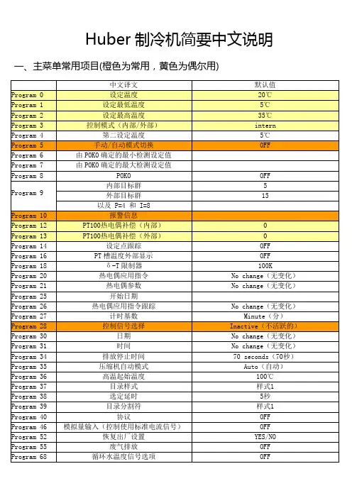
Huber制冷机简要中文说明一、主菜单常用项目(橙色为常用,黄色为偶尔用)常用操作备忘:1、切换手自动控制模式:进入Program 5,选择自动模式开启/关闭。
然后进入Program 28选择0(OFF)/5(standby)。
2、更改上下限温度:Program 1为温度下限。
Program 2为温度上限。
3、报警信息查询:Program 10。
4、内外温度显示:Program 3。
5、功率限制:Program180,加热功率限制;Program 181,制冷功率限制。
6、语言选择:Program 90。
二、常见报警信息1/0:主电源开启。
1/85:循环泵开启。
1/73:温度调节开启。
1/65:开启主电源故障自动诊断模式。
1/69:开机初始化所有错误(报警)。
2/79:通过红色的<0>键关机。
2/1…2/9:关闭No.1……NO.9的程序。
2/111:切断工控机的控制。
2/115:切断外部信号控制(Program 28:Stand By)。
4/0:允许无意义的信号。
4/1:允许信号开始/停止制冷机。
4/2:允许定义第二设定点。
4/3:允许调节方式的改变。
4/4:允许模拟输出信号改变。
4/5:允许信号是开始/停止信号。
5/0:无(闲置)。
5/1:温度波动监控。
5/2:POKO报警。
5/4:增压泵控制。
5/8:调节程序中的温度轨迹[1]。
5/16:调节程序中的温度轨迹[2]。
14/:数字接口状态错误。
15/1:控制器电源功率过低。
15/2:循环泵电源功率过低。
15/4:压缩机电源功率过低。
15/6:循环泵以及压缩机电源功率过低。
15/16:控制器电源功率过高。
15/32:循环泵电源功率过高。
15/64:压缩机电源功率过高。
15/96:循环泵以及压缩机电源功率过高。
17/:模拟信号设置的参数记忆错误(检查Program :137 138 139)。
18/:模拟量接口进入错误。
19/:(外部的)模拟量接口错误。

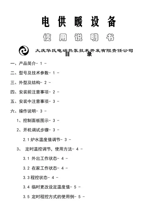
电供暖设备使用说明书大庆华氏电磁热泵技术开发有限责任公司目录一、产品简介- 1 -二、型号及技术参数- 1 -三、外型及结构- 2 -四、安装前注意事项- 2 -五、安装中注意事项- 3 -六、操作说明- 3 -1、控制面板图示- 3 -2、开机调试步骤- 3 -2.1炉水温度值调节- 3 -3、定时温控调节,使用方法- 4 -3.1 外出工作状态- 4 -3.2 在家工作状态- 4 -3.3程控状态- 4 -3.4 临时更改设定温度值- 5 -3.5 定时程控方式的使用例- 5 -3.6 设置说明- 5 -七、接线图- 6 -八、注意事项- 6 -使用前请详细阅读说明书一、产品简介本公司研制的电供暖设备具有无噪声、无污染物排放、运行安全、可靠以及温度可自由控制、采暖时间、采暖费用可自由掌握。
本产品可用于住宅、别墅等分户采暖及机关、学校、医院等单位的集中供暖。
可与各种热水散热器、热水热风幕、风机盘管及地热水管式供暖系统连接。
二、型号及技术参数三、外型及结构型号:4~18KW型号:30~36KW型号:38~50KW型号:60~108KW四、安装前注意事项确认电源(220V或AC380V三相四线),根据下表每相导线线径与炉本身功率匹配,确认标准铜线。
4~24KW型号产品的安装示意图30~108KW型号产品的安装示意图五、安装中注意事项1、供暖设备要水平稳固放置,必须设置膨胀水箱。
膨胀水箱必须与大气相通,膨胀水箱与炉连接之间不允许设置阀门,始终保证炉水与大气相通。
2、请安装在不会受潮的干燥地方,3、连接电源时接线牢固不易脱落,零线,火线不得接错,4、如系统内水中有杂质应设置过滤器。
5、必须设置接地线,6、安装设备应留有充分的可供维修的空间,左、右、前面距离墙面等不小于1米。
(60~108KW)六、操作说明1、控制面板图示2、开机调试步骤(开机前必须将供暖系统注满水并排除系统中的所有空气)2.1炉水温度值调节1)在接通电源前将3右显示窗有数字显示(炉水温度值)。
恒温循环水浴槽的操作是怎样的恒温循环水浴工作原理低温恒温循环水浴槽是接受机械制冷的低温液体循环设备,具有性能稳定、牢靠性高、功能全面、操作简便等多种优点,被广泛用于多个领域中。
操作方法(1)向工作室注入水至所需高度(之前应注意放水阀门是否在关闭状态。
放水阀在仪器左侧底部,打开左侧门可以看到)。
(2)开启恒温水浴的电源开关。
(3)将温控表设定到所需温度。
(4)开启加热系统。
(5)试验完毕,切断电源。
注意!温度掌控表的参数在出厂时已调好,使用者只可更改SV(温度设定)值,若需要更改温度掌控仪表的参数,请认真阅读温度掌控仪表的使用说明书。
注意事项(1)恒温水浴的使用电源为50Hz 200—240V的交流电源,电源电压过高会损坏恒温水浴上的仪器仪表。
(2)工作室应注入适量的水。
(3)加热管至少低于液面20mm。
(4)用户供应的电源插座电气额定参数应大于仪器的电气额定参数并有良好的接地措施。
(5)设备放置必要条件:设备后面距离墙壁应大于0.2米以上。
(6)适时检查漏电保护开关是否灵敏。
(7)再使用过程中水不要过满,离水浴上边至少保留10cm左右。
低温恒温循环水浴槽具有供应低温液体、低温水浴的作用。
结合旋转蒸发器、真空冷冻干燥箱、循环水式真空泵、磁力搅拌器等仪器,进行多功能低温下的化学反应作业及药物储存。
电热恒温循环水浴的保护装置是怎样的高精度电热恒温循环水浴基于自身的设备的特别性以及使用的多而杂性,所以,高精度电热恒温循环水浴,为了更好的运行。
所以,在高精度电热恒温循环水浴上设置了安全保护装置,那么高精度电热恒温循环水浴常见的保护装置有哪些呢?其实,依据高精度电热恒温循环水浴型号的不同,其所应当带有的保护装置也会稍有不同,比如风冷式高精度电热恒温循环水浴和水冷式高精度电热恒温循环水浴这两种不同的冷凝器和冷凝方式,那么它们所具备的保护装置就不尽相同,但两者也有很多相同之处。
针对压缩机的保护装置,基本上都比较仿佛。

低温冷却液循环泵的使用说明随着科技的进步和工业生产的不断发展,低温冷却液循环泵在实验室、医疗设备、制冷设备等领域得到了广泛的应用。
它通过低温冷却液的循环流动,能够为设备提供稳定的温度环境,保证设备正常运行。
本文就低温冷却液循环泵的使用进行详细介绍。
首先,使用低温冷却液循环泵前,我们需要了解其主要组成部分以及相关特点。
一般来说,低温冷却液循环泵主要由泵体、电机、冷凝器、控制面板和温度传感器等组件构成。
其中,泵体是循环液体的核心装置,电机提供动力,冷凝器用于将液体冷却,并通过传感器和控制面板实现自动控制。
此外,低温冷却液循环泵还具有小巧、便携、低噪音、高效稳定等特点。
接下来,我们来讨论低温冷却液循环泵的正确使用方法。
首先要确保泵体内的低温冷却液充足,通常使用液体为乙二醇或双氧水等。
在注入液体前,需先关闭电源并拔掉电源插头,以确保安全。
注意,液体注入时应缓慢进行,防止气泡进入循环泵,影响其正常工作。
注入液体后,可以重新插上电源插头,开启电源,然后按下控制面板上的启动按钮,这时低温冷却液循环泵就开始工作了。
同时,我们还要了解一些低温冷却液循环泵使用中的注意事项。
首先,使用过程中应保持泵体周围通风良好,并避免阳光直射、高温环境或湿度过大的地方。
其次,定期清洗泵体以及冷凝器表面的积灰,确保散热效果良好,避免因过热损坏泵体。
另外,为确保设备的长期稳定运行,还需定期更换泵体内的液体,并及时检查电机的运行情况。
如果发现异常,应立即停止使用,并联系专业技术人员进行维修。
此外,还有一些特殊情况下的应用技巧需要我们注意。
比如,在高温条件下使用低温冷却液循环泵时,可以选择合适的冷却液体,增加冷凝器的散热面积或者采取其他散热措施,以保证设备的安全运行。
又如在运输或长时间不使用的情况下,应先将泵体内的液体排空,以免造成渗漏或损坏。
这些操作虽然相对复杂,但都是为了保障低温冷却液循环泵的正常工作。
综上所述,低温冷却液循环泵在各个领域都有着重要的作用,使用方法和注意事项对其性能和寿命起着至关重要的作用。
Brookfield数字控制循环水浴操作手册Brookfield数字控制循环水浴操作手册目录Section 1 –简述1.1 拆箱1.2 内容物1.3 概述1.4 循环泵1.5 泵进口、出口连接1.6 循环回路1.7 水槽清洗1.8 环境和冷却管Section 2 –标准控制器信息2.1 前置和后置面板2.2 加热器/泵组件Section 3 –操作3.1 循环水浴放置3.2 注满水槽3.3 电源3.4 设定安全设置点3.5 选择温度单位3.6 设定上限3.7 设定设置点温度3.8 用户自定义预定温度3.9 粘贴条3.10 自动冷却操作3.11 控制器显示信息Section 4 –校正和维护4.1 校正4.2 加热器4.3 泵电机4.4 清洁4.5 水浴用水清洁4.6 冷凝器、通气孔和循环过滤器(仅针对冷/热循环水浴) Section 5 –故障排除5.1 仪器不运行(不加热、制冷或抽吸)5.2 泵不抽吸5.3 泵抽吸慢或不足5.4 不加热5.5 加热不足5.6 不制冷或制冷不足5.7 电子故障Section 6 –水浴液体Section 7 –服务和技术支持7.1 更换零件Section 8 –售后服务Section 9 –保证Section 10 –EC Declaration of ConformitySection 1 –简述1.1 拆箱水浴放置在特制的纸箱内,保留所有外包装和包装材料直到水浴装配并运行正常。
立即设置并运行水浴,以确认操作正常。
一周后,您的仪器可得到保修,但不能更换。
如果仪器被损坏或不能正常运行,联系运输公司,提出书面索赔要求,立即联系您的供货商。
将水槽中所有包装材料取出,在通电前,检查在加热器和泵周围确保没有其它东西。
本指南均适用于制冷型和水冷型循环水浴。
有关您所选的型号请参见相关指南。
1.2 内容物1.3 概述数字控制制冷/加热型和单加热型循环水浴是为独立使用水浴或通过外循环给外接设备提供精密温度控制而设计的。
河源恒温加热板使用说明
河源恒温加热板是一种高效、可靠的加热设备,广泛应用于化学、医药、生物、环保等行业中的实验室和工业生产中。
下面是该加热板的使用说明:
1.使用前,请仔细阅读产品说明书和安全注意事项,并确保加热板的电源和电压与实验室或工厂的电源相符,以避免电源过载。
2.将加热板放置在水平平稳的台面上,并保持加热板表面的清洁。
不要将加热板放置在易燃的物品旁边,以避免火灾和其他意外事故。
3.打开加热板的电源开关,并调整温度控制旋钮,以设置所需的加热温度。
加热板的数码显示屏将显示当前的温度。
4.当加热板达到所需的温度后,将待加热的样品或试剂瓶放置在加热板上,并用烧杯或试管架支撑。
5.加热过程中,请保持实验室或工厂的通风良好,以避免有害气体的积聚。
6.加热结束后,请关闭加热板的电源开关,并等待加热板冷却到室温后再进行清洁。
7.加热板的清洁,可使用湿布轻擦加热板表面,并用软刷清洁加热板的凹槽。
不要使用酸性或碱性清洁剂,以避免损坏加热板表面。
总之,河源恒温加热板是一种非常实用的加热设备,在使用时需要严格按照说明书和安全注意事项进行操作,以确保实验室或工厂的安全和实验结果的可靠性。
EnglishOperatingmanualHeating Immersion CirculatorEDD-77960 Seelbach / Germany( +49 7823 51-03 +49 7823 2491š***************ü www.julabo.de19510230.doc16.07.042ContentsOperating manual Pages 2 to 10Operating instructions Pages 11 to 21Congratulations!You have made an excellent choice.JULABO thanks you for the trust you have placed in us.This operating manual has been designed to help you gain an understanding of the principles of operating and possibilities of our circulators. For optimum utilization of all functions, we recommend that you thoroughly study this manual prior to beginning operation.Quality Management SystemISO 90012000W e a r ec e r t i f i ed The JULABO Q uality M anagement S ystem:Development, production and distribution of temperature application instruments for research and industries conform to the requirements according to DIN EN ISO 9001:2000.Certificate Registration No. QA 051004008.Unpacking and checkingUnpack the circulator and accessories and check for damages incurred during transit.These should be reported to the responsible carrier, railway, or postal authority, and a request for a damage report should be made. These instructions must be followed fully for us to guarantee our full support of your claim for protecting against loss from concealed damage. The form required for filing such a claim will be provided by the carrier.Printed in GermanyChanges without prior notification reservedED TABLE OF CONTENTSOperating manual (4)Description (4)Operator responsibility – Safety recommendations (4)EC Declaration of Conformity (7)Warranty conditions (8)Technical specifications (9)Operating instructions (11)1. Operating controls and functional elements (11)2. Safety notes for the user (12)3. Preparations (12)3.1. Installation (12)3.2. Bath fluids (13)3.3. Temperature application to external systems (14)3.3.1. Pump set (14)3.3.2. Tubing (14)3.4. Countercooling (15)3.5. Adjusting the pump flow (16)4. Operating procedures (16)4.1. Power connection (16)4.2. Switching on / Start - Stop (17)4.3. Automatic / non-automatic start mode (17)4.4. Setting the temperatures (18)4.5. Excess temperature protection (18)5. Troubleshooting guide / Error messages (19)6. Safety recommendations (20)7. Cleaning the unit (21)3Operating manual4Operating manualDescriptionJULABO circulators have been designed for temperature application to specific fluids ina bath tank.þ The circulators are operated via the splash-proof keypad. Theimplemented microprocessor technology allows to set and to store thesetpoint that can be indicated on the LED temperature display.þ The PID temperature control adapts the heat supplied to the thermalrequirements of the bath.þ The excess temperature protection conforming to IEC 61010-2-010 is asafety installation independent from the control circuit. The safety valueis set using a tool (screwdriver).þ The circulator conforms to the relevant requirements specified by European guidelines.Operator responsibility – Safety recommendationsThe products of JULABO Labortechnik GmbH warrant a safe operation if installation,operation and maintenance is carried out according to common safety regulations. This section informs you about potential dangers that may arise from operating the circulator and also mentions the most important safety precautions.ED5Persons:The operator is responsible for the qualification of the personnel operating the units.The operator should be constantly informed about the dangers involved with their job activities as well as preventive actions.Make sure all persons expected to carry out operation, installation and maintenance of the unit read and understand the safety information and operating instructions.If you have any questions concerning the operation of your unit or the information in this manual, please contact us!Contact JULABO Labortechnik GmbHEisenbahnstrasse 45D-77960 Seelbach / Germany ( +49 7823 51-03 +49 7823 2491š **************ü www.julabo.deHandling:You received a product conceived for industrial use. Nevertheless, avoid strikes to the housing, vibrations, damages to the keypad foil (keys, display) or contamination.Make sure the product is regularly checked for proper condition. Regularly check (at least every 2 years) the proper condition of the mandatory, warning, prohibition and safety labels.Take care that the mains supply features a low impedance to avoid any negative affects on the instrument being operated in the same mains.This unit is designed for operation in a controlled electromagnetic environment. This means that transmitting devices (e.g. cellular phones) should not be used in the immediate vicinity.Magnetic radiation may influence other units with components susceptible to magnetic fields(e.g. a monitor). We recommend to keep a minimum distance of 1 m.Permissible ambient temperature: max. 40 °C, min. 5 °C.Permissible relative air humidity: 50 % (40 °C).Do not store in an aggressive atmosphere. Protect from contaminations. Do not expose to sunlight.Operating manual Operation:Only qualified personnel is authorized to perform configuration, installation, maintainance and repairs of the circulator.Routine operation can also be carried out by untrained personnel who should however be instructed by trained personnel. The summarized user guidance (short manual) and the specification table with information on individual parameters are sufficient for this. Use:The bath may not be filled with flammable materials. Fire hazard!Only use recommended materials (bath fluids). Only use non-acid materials. Particular care and attention is necessary because of the wide operating range.There are thermal dangers: Burn, scald, hot steam, hot parts and surfaces that can be touched.Observe the instructions in the manuals for instruments of a different make that you connect to the circulator, particularly the respective safety recommendations. Also observe the pin assignment of plugs and technical specifications of the products.6ED7EC Declaration of ConformityHeating Immersion Circulator:EDThe product mentioned complies with the requirements outlined by the following European guidelines:Guideline 73/23/EEC of the Council of 19 February 1973 with respect to legalharmonization of the member countries concerning electric devicesfor use within certain voltage limitsGuideline 89/336/EEC of the Council of 3 May 1989 with respect to legal harmonizationof the member countries concerning electromagnetic compatibilityGuideline 98/37/EC of the European Parliament and the Council of 22 June 1998 forharmonization of legal and administrative regulations of the membercountries with respect to machineryThe units conform to the following standards:EN 1050: 1996-11EN 292-1: 1991-09EN 292-2: 1991-09EN 61010-1: 2001EN 61010-2-10: 1994-07EN 60204-1: 1997-12EN 563: 1994-06EN 61326: 1997 + A1: 1998 + A2: 2001Eisenbahnstr. 45D-77960 Seelbach / GermanyOperating manualWarranty conditionsJULABO Labortechnik GmbH warrants its products against defects in material or in workmanship, when used under appropriate conditions and in accordance with appropriate operating instructionsfor a period of ONE YEAR.Extension of the warranty period – free of chargeWith the ‘1PLUS warranty’ the user receives a free of charge extension to the warranty of up to 24 months, limited to a maximum of 10 000 working hours.To apply for this extended warranty the user must register the unit on the JULABO web site www.julabo.de, indicating the serial no. The extended warranty will apply from the date of JULABO Labortechnik GmbH’s original invoice.JULABO Labortechnik GmbH reserves the right to decide the validity of any warranty claim. In case of faults arising either due to faulty materials or workmanship, parts will be repaired or replaced free of charge, or a new replacement unit will be supplied.Any other compensation claims are excluded from this guarantee.8EDTechnical specificationsEDWorking temperature range°C20 (100)Temperature stability°C±0.03Temperature selection digitalTemperature indication LEDResolution°C0.1Temperature control PID1Heater wattage(at 230 V) W2000or(at 115V) W1000Circulating pump:discharge, max.at 0 bar l/min15pressure, max. at 0 l bar0.35Overall dimensions (WxDxH)cm13x15x33Usable bath depth cm from 8 to 16.5Weight kg 3.3Ambient temperature°C 5 (40)Mains power connection V/ Hz190 ... 253 / 50-60or V/Hz100 ... 115 / 50-60Current input at 208 V / 230 V A8 / 9kW 1.1 (at 115V)All measurements have been carried out at:rated voltage and frequency operating temperature: 70 °Cambient temperature: 20 °C bath fluid: waterTechnical changes without prior notification reserved.9Operating manual Safety installations according to IEC 61010-2-010:Excess temperature protection adjustable from 20 to 120 °C Classification according to DIN 12876-1class IAlarm indication optical + audible (permanent) Environmental conditions according to EN 61 010, part 1:Use only indoor.Altitude up to 2000 m - normal zero.Ambient temperature: +5 ... +40 °C (for storage and transportation)Air humidity:Max. rel. humidity 80 % for temperatures up to +31 °C,linear decrease down to 50 % relative humidity at a temperature of +40 °CProtection class according to EN 60 529IP21Power supply: according to class 1, VDE 0106 T1not for use in explosive atmosphereMax. mains fluctuation of ±10 % are permissible.Overvoltage category IIPollution degree 2Standards for interference resistance EN 61326: 1997 + A1: 1998 + A2: 2001Emitted interferencesThe unit adheres to the threshold values for emitted interferencesaccording to table 3.Interference resistanceThe unit conforms to the requirements according to table B.1.10EDOperating instructions1.Operating controls and functional elementsFront viewRear view 5080120001781091Mains power switch, illuminated2Edit keys (increase/decrease setting)3Enter key (store)4LED temperature display, menu indication 5Control indicator –Heating 6Control indicator – Alarm 7°C8012020Adjustable excess temperature protection according to IEC 61010-2-010Rear8Mains fuses: Safety cutout 15 A 9Threaded fitting (10 mm) for stand rod attachment 10Mains power cable with plugSafety notes for the user 2.Safety notes for the user3.PreparationsThe heating immersion circulator is mounted using abath attachment clamp (21) designed for bath wallthicknesses up to 26 mm.Use the two sleeves (22) supplied with the unit toreduce the immersion depth from 165 mm to 145 mm(see drawing).For use with glass vessels an upright stand rod (orderno. 8 970 020), available as optional accessory, maybe screwed in the threaded fitting (17).ED 3.2. Bath fluids•Recommended bath fluid: deionized water.PreparationsWater bath protective mediaWe recommend the use of the "Aqua-Stabil" protectivemedia to eliminate the formation of algae, bacteria, andother micro-organismsOrder No.Description8 940 006 6 bottles each 100 ml8 940 01212 bottles each 100 ml3.3.Temperature application to external systemsThe circulator is used for temperature application toexternal, closed systems (loop circuit).3.3.1.Pump setAccessoriesOrder No. Description 8 970 140 Pump setMounting the pump set:• Remove the bath attachment clamp (21).• Screw the pump set to the circulator, and then fix thebath attachment clamp to the pump set.• Slide the short piece of tubing supplied with the pump set onto the short pump nozzle and the pump connector(23).• Thus the total immersion depth is reduced to 145 mm.• Adjusting the pump for external bath circulation seeexample D page 16.Connecting an external system:• Unscrew the collar nuts from the pump connector (24a).• Slide the tubing onto the pump connectors for feed and3.3.2.TubingRecommended tubing:Order No. LengthTemperature range 8930008 2 mCR ® tubing 8 mm ID -20 °C ... 120 °C 8930010 2 mCR ® tubing 10 mm ID -20 °C ... 120 °C 8930108 1 mViton tubing 8 mm ID -50 °C ... 200 °C 8930110 1 m Viton tubing 10 mm ID -50 °C ... 200 °CED Order No. Length Temperature range8930410 2 m Insulation for tubing 8 mm ID or 10 mm ID-50 °C ... 100 °C3.4.CountercoolingFor applications near the ambient temperature, the cooling coil (order no. 8 970 105) must be connected to the water mains.Mounting the cooling coil:•Remove the bath attachment clamp (21).•Screw the cooling coil to the circulator, and then fix the bath attachment clamp to the cooling coil.•Thus the total immersion depth is reduced to 145 mm.•Using tubing, connect the cooling coil (25a) to the tap water supply, and lead the tap water in a sink through the return connector (25b).i A specific water flow rate of 45 ml/minute issufficient to compensate for the characteristictemperature.i For applications near ambient temperature(20 °C), the cooling water temperature should atleast be 5 °C below the working temperature.Operating procedures 3.5.Adjusting the pump flowThe pump flow is pre-adjusted in the factory and can bemodified to suit user requirements.•Using a screwdriver turn the screw (1) anti-clockwiseby 360 °.•Using flat pliers turn the marking of the slide (2) to thedesired position.•Tighten the screw.ADExamples:Internal applications in the bathA100 % internal bath circulation(for large bath tanks)B Reduced internal bath circulation(for smooth surface of bath fluid)External/internal applicationsC40 % external discharge,60 % internal circulation(for large bath tanks)D80 % external discharge,20 % internal circulation(for small bath tanks)4.Operating procedures4.1.Power connectionCheck to make sure that the line voltage matches the supplyvoltage specified on the identification plate.Deviations of ±10 % are permissible.ED4.2.Switching on / Start - Stop•Switching on:Turn on the mains power switch (1).•The unit performs a self-test. All segments of the 4-digit LEDtemperature DISPLAY and all indicator lights will illuminate(as illustrated on the left).The display "OFF" indicates the unit is ready to operate (standbymode).Start:•for about 4 seconds.The LED temperature DISPLAY indicates the actual bathtemperature.Stop:•Turn the unit off with the mains power switch.4.3.Automatic / non-automatic start modeŒ•turn on the circulator with the mains power switch.For a short while the LED temperature DISPLAY indicates theeffective start mode:ðAUTOSTART on.ðAUTOSTART off.NOTE:The circulator has been configured and supplied by JULABOaccording to N.A.M.U.R. recommendations. This means for thestart mode, that the unit must enter a safe operating state after apower failure (non-automatic start mode). This safe operatingstate is indicated by …OFF“ on the LED temperature display. Acomplete shutdown of the main functional elements such asheater and circulating pump is effected simultaneously.Should such a safety standard not be required, the AUTOSTARTfunction (automatic start mode) may be activated, thus allowingthe start of the circulator directly by pressing the mains powerswitch or using a timer.Operating procedures4.4.Setting the temperaturesFactory setting:25 °C i Setting can be carried out in the start/stop condition.1.Press one of the keys for a short moment. The setpointvalue instead of the actual value is indicated on the display for about 8 seconds. The value can now be changed.2.Change value:Press to set a higher value.Press to set a lower value.Keep the keys depressed for the value to change fast.3.4.5.Excess temperature protectionThis safety installation is independent of the control circuit.When the temperature of the bath fluid has reached the safetytemperature, a complete shutdown of the heater and pump iseffected.Setting range: 20 °C to 120 °C•Using a screwdriver turn the setting screw to the desiredvalue.Recommendation:Set the excess temperature protector at 5 to 10 °C above theworking temperature setpoint.ED5.Troubleshooting guide / Error messagesU Whenever the microprocessor electronics registers a failure, acomplete shutdown of the heater and circulating pump is performed.The alarm light "" illuminates and a continuous signal tonesounds.The LED temperature display indicates the cause for the alarm inform of a code.•Defect of the working or safety temperature sensor.•The safety temperature value lies below the working temperature setpoint.Set the excess temperature protection to a higher value.•The circulator is operated without bath fluid, or the liquid level is insufficient.Replenish the bath tank with the bath fluid.•Tube breakage has occured (insufficient filling level due to excessive bath fluid pumped out). Replace the tubing andreplenish the bath tank with the bath fluid.•The wires of the working temperature sensor are interrupted orshort-circuited.After eliminating the malfunction, press the mains power switch off and on again to cancel the alarm state.If the unit cannot be returned to operation, contact an authorized JULABO service station.Disturbances that are not indicated.Pump motor overload protectionThe pump motor is protected against overloading. After a shortcooling interval, the motor will automatically start running.Mains fusesThe mains fuses on the rear of the unit are safety cutouts – 15A.Safety recommendations6.Safety recommendationsFollow the safety recommendations to prevent damage to persons orproperty. Further, the valid safety instructions for working placesmust be followed.ED217.Cleaning the unitFor cleaning the bath tank and the immersed parts of the circulator, use low surface tension water (e.g., soap suds).Clean the outside of the unit using a wet cloth and low surface tension water.The circulator is designed for continuous operation under normal conditions. Periodic maintenance is not required.The tank should be filled only with a bath fluid recommended byJULABO. To avoid contamination, it is essential to change the bath fluid from time to time.RepairsBefore asking for a service technician or returning a JULABOcirculator for repair, please contact an authorized JULABO service station.When returning the unit:• Clean the unit in order to avoid any harm to the service personnel.• Attach a short fault description.• During transport the unit has to stand upright. Mark the packing correspondingly.• When returning a unit, take care of careful and adequate packing.• JULABO is not responsible for damages that might occur frominsufficient packing.。
EU declaration of conformity regarding energy consumption according to (EU) 2019/2019Energy Label (EU) 2019/2016Applied standard EN 62552:2020Product information sheetSupplier’s name or trade markLiebherrSupplier’s addressLiebherr-Hausgeräte GmbH Memminger Straße 77-7988416 OchsenhausenGermany Model identifier CBNbe 6256_992756851Electrical data Voltage 220-240 V ~Frequency 50 Hz Connection rating1.5 AType of refrigerating appliance Low-noise appliance no Design typefreestandingWine storage appliance noOther refrigerating applianceyesGeneral product parametersParameterValue ParameterValueHeight 2039Width 910Overalldimensions (millimetre)Depth615Total volume (dm³ or l)522EEI106Energy efficiency class F Airborne acoustical noise emissions (dB(A) re 1 pW)42Airborne acoustical noise emission class D Annual energy consumption (kWh/a)341Minimum ambient temperature (°C), for which the refrigerating appliance is suitable10Climate classextended temperate, temperate, subtropical, tropicalMaximum ambient temperature (°C), for which the refrigerating appliance is suitable43Winter setting noCompartment ParametersCompartment parameters and valuesCompartment typeCompartmentVolume (dm³ orl)Recommendedtemperaturesetting foroptimised foodstorage (°C)Freezingcapacity (kg/24h)Defrosting type(auto-defrost = A,manual defrost = M)Pantry no----Wine storage no----Cellar no----Fresh food yes292.25-A Chill yes70.60-A0-star or ice-makingno----1-star no----2-star no----3-star no----4-star yes159.5-1810.0A 2-star section no----Variabletemperaturecompartmentno----For 4-star compartmentsFast freeze facility yesFor wine storage appliancesNumber of standard wine bottles-Light source parametersLighting technology used LEDLight Source 3Energy efficiency class GLighting technology used LEDLight Source 2Energy efficiency class GLighting technology used LEDLight Source 1Energy efficiency class FMinimum duration of the guarantee offered by the manufacturer: 24 monthAdditional information: -Weblink to the manufacturer’s website, where the information in point 4(a) Annex of Commission Regulation (EU) 2019/2019 (4) (2) is found:https:///The energy consumption was confirmed by measurements according to EN 62552:2020.。
IndustrialRailwaysAgriculturalConstructionUtilityMaterialHandlingForestryOffshoreELH Series - Hydraulic Fan DriveAir Cooled Oil Coolers for Mobile ApplicationsDescriptionThese coolers use a combination of high performance cooling elements combined with a high capacity hydraulic fan drive to give long, trouble free operation in mobile hydraulic applications. The compact design allows the coolers to fit most equipment and provides the highest cooling performance in heat dissipation while minimizing space required.Features• E LH 2 - 5 coolers are designed with the inlet/outlet ports facing towards the back to help reduce fittings • Available with internal pressure and temperature bypass • All units feature a built in thermostat port • Up to 180 HP cooling capacity• Rated flows up to 90 gpm (consult factory for higher flows)• H ydraulic motor drive offers more cooling in a smaller package • O ptional thermal speed control and pressure relief(Consult Factory)Hydraulic SymbolApplicationsGeneralConstructionHousing Welded SteelHeat Exchanger Aluminum - Heavy Duty bar and plate Fan PlasticMotorAluminum housing, Steel gears and shaft Maximum Oil Temperature 266ºF (130ºC)Maximum Operating Pressure 230 psi (16 bar)Mounting Orientation All positionsFan Rotation See arrow on housingFiltrationISO/DIS 4406 Code 19/16- Filtration grade B25>75Maximum Outlet Side Pressure Motor 1740 psi (120 bar)Maximum Drain Pressure Motor 29 psi (2 bar)Fluid Viscosity Range Motor 10 - 600 cst. (recommended 30 - 45 cst.)Fluid Temperature RangeMotorUp to 194˚ F (90ºC)t e s y o f C M A /F l o d y n e /H y d r a d y n e ▪ M o t i o n C o n t r o l ▪ H y d r a u l i c ▪ P n e u m a t i c ▪ E l e c t r i c a l ▪ M e c h a n i c a l ▪ (800) 426-5480 ▪ w w w .c m a f h .c o mModel CodeELH 2 1.5 H6.3 S IBT 45 - 2 ModelELH = Air Cooled Oil Cooler with Hydraulic Fan DriveSize(See the heat transfer table found on page 16 to determine the proper size.)234567891011Modification Number (latest version always supplied)Hydraulic Motor Drive DisplacementH6.3 = 6.3 ccm/rev (available only on ELH 2-6 and ELH 8)H14 = 14 ccm/revH22 = 22 ccm/revAir Flow DirectionS = Suction (standard)B = BlowingAccessoriesF = Optional foot mount (sizes 2 - 4 only)IBT = thermostatic bypass valveIBP = integrated pressure bypass valveOpening Temperature (IBT only)Opening Temp. Closing Temp.45 = 113°F (45°C) 131°F (55°C)50 = 130°F (55°C) 150°F (65°C)60 = 140°F (60°C) 158°F (70°C)Opening Pressure Drop (IBT & IBP only)2 = 2 bar (29 psi)3 = 3 bar (45 psi)4 = 4 bar (58psi) (IBP only)CMA/Flodyne/Hydradyne▪MotionControl▪Hydraulic▪Pneumatic▪Electrical▪Mechanical▪(8)426-548▪www.cmafh.co mPressure Drop @ 30cSt(tolerance ± 5%)Pressure differential ∆p depending on flow rate Q and the viscosity of the oil.ELH SeriesHeat Dissipation @∆T =72ºF(tolerance ± 5%)Cooling capacity depends on oil flow and the temperature differential (∆T) between the oil inlet and air inlet.Sizes 6 - 11Sizes 2 - 5ELH-3ELH-5ELH-2ELH-4ELH-6ELH-7ELH-8ELH-9ELH-10ELH-11454035302520151050051015202530354045505560657075808551015202530354045505560657075808590510152025303540455055606570Oil Flow [GPM]Oil Flow [GPM]Oil Flow [GPM]P r e s s u r e D r o p [P S I ]2252001751501251007550250H e a t D i s s i p a t i o n [H P ]ELH-4 3000 RPMELH-5 2000 RPM ELH-4 1500 RPM ELH-2 1500 RPMELH-2 3000 RPM ELH-3 3000 RPMELH-3 1500 RPMELH-5 3000 RPMH e a t D i s s i p a t i o n [H P ]45504035302520151050• For other viscosities, the result must be multiplied by the K factors belowC M A /F l o d y n e /H y d r a d y n e ▪ M o t i o n C o n t r o l ▪ H y d r a u l i c ▪ P n e u m a t i c ▪ E l e c t r i c a l ▪ M e c h a n i c a l ▪ (800) 426-5480 ▪ w w w .c m a f h .c o mELH SeriesDimensions Sizes 2 - 4Size 5(6X)Dimensions are for general information only, all critical dimensions should be verified by requesting a certified print. Dimensions are in inches.t e s y o f C M A /F l o d y n e /H y d r a d y n e ▪ M o t i o n C o n t r o l ▪ H y d r a u l i c ▪ P n e u m a t i c ▪ E l e c t r i c a l ▪ M e c h a n i c a l ▪ (800) 426-5480 ▪ w w w .c m a f h .c o mELH SeriesDimensions Sizes 6Sizes 7 - 8Dimensions are for general information only, all critical dimensions should be verified by requesting a certified print. Dimensions are in inches.t e s y o H y d r a d y n e ▪ M o t i o n C o n t r o l ▪ H y d r a u l i c ▪ P n e u t r i c a l ▪ M e c h a n i c a l ▪ (800) 426-5480 ▪ w w w .c m a f h .c o mELH SeriesDimensions Sizes 9 - 11ELH Series 2-4 Mounting Foot BracketDimensions1.97”50mm1.42”36mm0.71”18mm4mmDimensions are for general information only, all critical dimensions should be verified by requesting a certified print. Dimensions are in inches/mm.t e s y o f C M A /F l o d y n e /H y d r a d y n e ▪ M o t i o n C o n t r o l ▪ H y d r a u l i c ▪ P n e u m a t i c ▪ E l e c t r i c a l ▪ M e c h a n i c a l ▪ (800) 426-5480 ▪ w w w .c m a f h .c o m。
冷冻水浴恒温振荡器使用方法恒温振荡器操作规程水浴恒温振荡器是一种温度可控的恒温水浴槽和振荡器相结合的生化仪器,紧要适用于各大中院校、医疗、石油化工、卫生防疫、环境监测等科研部门作生物、生化、细胞、水浴恒温振荡器是一种温度可控的恒温水浴槽和振荡器相结合的生化仪器,紧要适用于各大中院校、医疗、石油化工、卫生防疫、环境监测等科研部门作生物、生化、细胞、菌种等各种液态、固态化合物的振荡培育。
冷冻水浴恒温振荡器使用方法首先检查仪器水阀是否关闭,加水至适当高度,然后将仪器的电源插头插在容量不小于2千瓦,有“接地”的电源上,将定时器选至你需要的工作时间,或选至常开位置,功能转换开关(扭子开关)拨至OFF位置。
按下电源开关,电源指示灯亮表明机内电源已经接通,旋动调速旋钮选择所需振荡频率。
1、如需加热,拨动功能转换开关至加热位置(向左拨),此时加热指示灯和加热温控表亮,加热部分已进入工作状态,取下温控面罩,“0—100℃”未预置温度选择,如你需要将温度掌控在某一区域,只需将刻度旋钮选至你需将掌控的某一温度上,即可进行恒温。
绿色指示灯亮,表明加热管工作,红色指示灯亮表明加热停止,数显表所示温度即为水箱内的实际水温。
2、如需制冷拨动功能转换开关至制冷位置(向右拨),此时制冷指示灯和制冷温控表亮,制冷部分已进入工作状态,拨动显示选择开关至左边,用小罗丝批旋动上限设定,调至所需制冷温度,已进入制冷、恒温状态,再将显示选择开关拨至中心位置,制冷温控表梭显示温度即为水箱内的实际水温。
注、需制冷至0℃以下速度快***好加防冻液,防冻液与水的比例1:1、—专业分析仪器服务平台,试验室仪器设备交易网,仪器行业专业网络宣扬媒体。
相关热词:等离子清洗机,反应釜,旋转蒸发仪,高精度温湿度计,露点仪,高效液相色谱仪价格,霉菌试验箱,跌落试验台,离子色谱仪价格,噪声计,高压灭菌器,集菌仪,接地电阻测试仪型号,柱温箱,旋涡混合仪,电热套,场强仪万能材料试验机价格,洗瓶机,匀浆机,耐候试验箱,熔融指数仪,透射电子显微镜。
SYSTEMRepresentative photo only,some models may vary in appearance.June2005EBP1800240030003600420048006000 EBX/EBXX18002400--3600--48006000Rows/Fins per inch EBP2/14.53/14.53/14.53/14.53/14.53/14.53/14.5 EBX/EBXX3/14.53/14.5--3/14.5--3/14.53/14.5 Face Area(Sq.Ft.)EBP 2.23 2.23 2.97 2.97 3.46 4.45 5.93 EBX/EBXX 2.97 2.97-- 3.46-- 5.937.42 Configuration Slope Slope Slope Slope Slope A A Line Sizes/Liquid(inch)5/165/165/163/83/83/83/8 Line Sizes/Suction(inch)3/43/43/47/87/87/87/8CFM(Nominal)EBP60080010001200140016002000 EBX/EBXX6001000--1400--16002000 Motor HP(PSC)EBP1/51/41/31/31/23/43/4 EBX/EBXX1/51/3--1/2--3/43/4 Filter Size(inches)EBP13x21½163/8x21½197/8x21½Filter Size(inches)EBX/EBXX13x21½163/8x21½--197/8x21½--197/8x21½235/16x21½Unit Weight(lbs.)92100117118137150167Shipping Weight(lbs.)96112120127146157175 UNIT SPECIFICATIONS--Using No Heat KitMaximum RecommendedOvercurrent Supply WireSupply Maximum Branch Protective75˚C.Copper Ground No Heat Supply Circuit Circuit Motor Total Circuit Device Max.Wire Model Volts Phase Hertz No.AMPS.AMPS.Ampacity(AMPS.)No.Size Length(Ft)No.Size EBAC01PLG240160Single 6.0 6.07.515214104114 208160Single 6.0 6.07.51521490114DIInlet AirSPECIFICATION SUBJECT TO CHANGE WITHOUT NOTICEEXTERNAL STATIC PRESSURE(Inches Water Column)Model Blower0.100.200.300.400.500.60 and Size Motor Speed208V230V208V230V208V230V208V230V208V230V208V230V EBP High660725615675565625500565405470----/EBX1800Low585650540605490555420485345395----High940975890925835865780805715735635650 EBP2400Low820900785855745805700750640680545575 High945975900930840870780805695725560595 EBX Medium835900795855745800690740610650470510 /EBXX2400Low605695575665530625485580425510340395 High10751170103011159851055920990850910750805 EBP3000Low825960810935790890750845690780590680 High13201405126513451205128011351210106011209601025 EBP3600Low1100121510701170102011159601060890980805895 High148515501425149013651420130013501230127511501190 EBX Medium12351380120013251160126511101210105511409851070 /EBXX3600Low1035118510101150980111594010708901010825935 High158017101540165514951595144015301375144512901355Medium140015701375152513501480130514251255136011751280 EBP4200Low119513751180135011651325113512851085124010201160EBPHigh188019351785183017001735161516451520155514301460 /EBX/Medium174018401660175015851660151015751435148513501390EBXX4800Low142516051395155513601495131514301255136011701270EBPHigh214522452085218520302115196520451905197518301895 /EBX/Medium202521751970211019152050186019801805190517401830EBXX6000Low168018951655185516251810159517651555170515001645 NOTES:1.Airflow based upon dry coil at230V with factory approved filter and electric heater(2element heater sizes18through36,3element heater sizes 42through60).2.Not recommended for use above0.60inches water column external static pressure.EBP1800.050EBP2400.056EBP3000.065EBP3600.070EBP4200.072EBP4800.076EBP6000.090NOTES:All EBX&EBXX Models are equiped with a TXV(no piston)SPECIFICATION SUBJECT TO CHANGE WITHOUT NOTICEFAN COIL HEATER kWSIZES3589101518202430185********--600*----------24700700700--700775*--------30--875875--875875--1060*----36--1050970970970920--1040----42----122512251225122512251225----48----14001400140014001400140014001400 60----17501750175017501750175017501750 *Indicates medium speed(blue).All other motor speeds at low tap.CFMUNIT SIZE400600800100012001400160018002000 180.020.0440.075------------24--0.0440.0750.110----------30----0.0480.0720.100--------36------0.0720.1000.130------42--------0.0700.0920.120----48----------0.0920.1200.152--60------------0.1200.1520.18718--3642--60HEATER ELEMENTS kW EXTERNAL STATICPRESSURECORRECTIONHEATER ELEMENTS kWEXTERNAL STATICPRESSURECORRECTION00+.0200+.0413,5+.0128,10+.0228,10039,15039,15--.02420--.02420--.04618,24,30--.10The airflow performance data was developed using fan coils with10--kW electric heaters(2elements)in the18through36size units and15--kW heaters (3elements)in the042through060size units.For fan coils with heaters of a different number of elements,the external available static at a given CFM from the curve may be corrected by adding or subtracting available external static pressure as indicated above.CFMUNIT SIZE50060070080090010001100120013001350 180.0230.0340.044--------------240.0350.0510.0660.0800.091----------30------0.0510.0630.0730.081------36----------0.0730.0810.0910.0980.102CFMUNIT SIZE120013001400150016001700180019002000 420.0750.0830.0910.098----------48----0.0660.0730.0800.0860.091----60--------0.0510.0570.0630.0690.073SPECIFICATION SUBJECT TO CHANGE WITHOUT NOTICESPECIFICATION SUBJECT TO CHANGE WITHOUT NOTICEHeater Amps p 208/230VHeater ModelkWPhaseInternalCircuit ProtectionCircuit Dual Circuit230v208v Single L1,L2L3,L4EHK05AKN 15 3.81None 18.1/20.0----EHK05AKN 25 3.81None 18.1/20.0----EHK07AKN 8 6.01None 28.9/32.0----EHK07AKB 8 6.01Ckt Bkr 28.9/32.0----EHK09AKCN 9 6.81None 32.8/36.0----EHK09AKCN [9 6.83None 18.8/20.8----EHK10AKN 107.51None 36.2/40.0----EHK10AKB 107.51Ckt Bkr 36.2/40.0----EHK15AKF 1511.31Fuse 54.2/59.936.2/40.018.1/20.0EHK15AKB 1511.31Ckt Bkr --36.2/40.018.1/20.0EHK15AHN 1511.33None 31.3/34.6----EHK18AHN 1813.53None 37.6/41.5----EHK20AKF 2015.01Fuse 72.3/79.936.2/40.036.2/40.0EHK20AKB 2015.01Ckt Bkr --36.2/40.036.2/40.0]2418.03Fuse 50.1/55.4----EHK25AHCF 2418.01Fuse 86.7/95.5----]3022.53Fuse 62.6/69.2----EHK30AHCF 3022.51Fuse109/120----Branch CircuitMin.Min.Length ModelAmpacity 208/230V **Wire Size (AWG)208/230V ll Min.Gnd.Wire Size208/230V Max Fuse/Ckt Bkr Amps Max Wire 208/230V (ft.)[[Heater Single Cir-Dual Circuit Single Dual Circuit Single Dual Circuit Single Dual Circuit Single Dual Circuit cuitL1,L2L3,L4Circuit L1,L2L3,L4Circuit L1,L2L3,L4Circuit L1,L2L3,L4Circuit L1,L2L3,L4EHK05AKN 126.0/28.4----10/10----10/10----30/30----66/66----EHK05AKN 231.2/33.5----8/8----10/10----35/35----85/88----EHK05AKB 126.0/28.4----10/10----10/10----30/30----66/66----EHK05AKB 231.2/33.5----8/8----10/10----35/35----85/88----EHK07AKN 44.7/48.5----8/8----10/10----45/50----59/60----EHK07AKB 44.7/48.5----8/8----10/10----45/50----59/60----EHK09AKCN 49.5/53.5----8/6----10/10----50/60----54/87----EHK09AKCN [32.0/34.5----8/8----10/10----35/35----83/85----EHK10AKN 53.8/58.5----6/6----10/10----60/60----78/80----EHK10AKB 53.8/58.5----6/6----10/10----60/60----78/80----EHK15AKF 76.3/83.453.8/58.522.7/25.04/46/610/108/810/1010/1080/9060/6025/2588/8978/8075/76EHK15AKB --53.8/58.522.7/25.0--6/610/10--10/1010/10--60/6025/25--78/8075/76EHK15AHN 47.7/51.8----8/6----10/10----50/60----56/90----EHK18AHN 55.5/60.4----6/6----10/8----60/70----76/77----EHK20AKF 98.9/108.453.8/58.545.3/50.03/26/68/88/610/1010/10100/11060/6050/5085/10978/8059/59EHK20AKB --53.8/58.545.3/50.0--6/68/8--10/1010/10--60/6050/50--78/8059/5971.2/77.8----4/4----8/8----80/80----94/95----EHK25AHCF ]116.9/127.9----1/1----6/6----125/150----115/116----86.8/95.0----3/3----8/8----90/100----97/98----EHK30AHCF ]144.8/158.5----0/00----6/6----150/175----117/150----]Field convertible to 1phase,single or multiple supply circuit.[Field convertible to 3phase.**Includes blower motor amps of largest fan coil used with heater.ll Copper wire must be used.If other than uncoated (non--plated),75Degrees C ambient,copper wire (solid wire for 10AWG andsmaller,stranded wire for larger than 10AWG)is used,consult applicable tables of the National Electric Code (ANSI/NFPA 70).[[Length shown is as measured 1way along wire path between unit and service panel for a voltage drop not to exceed 2%.NOTES :1.For fan coil sizes 18--36.2.For fan coil sizes 42--60.Model Description Use With EHK05AKN15kW Single Phase AllEHK07AKN18kW Single Phase AllEHKO7AKB18kW Single Phase AllEHK09AKCN19kW/Single Phase(Field convertible to3phase)AllEHK10AKN110kW Single Phase AllEHK10AKB110kW Single Phase AllEHK15AKF115kW Single Phase2--5TonEHK15AKB115kW Single Phase2--5TonEHK15AHN115kW3Phase2--5TonEHK18AHN118kW3Phase31/2--5TonEHK20AKF120kW Single Phase21/2--5TonEHK20AKB120kW Single Phase21/2--5TonEHK25AHCF124kW/3Phase(Field convertible to single phase)4--5TonEHK30AHCF130kW/3Phase(Field convertible to single phase)4--5TonAll AKB Models are Circuit Breaker ModelsDisconnect Kit EBAC01DSC All Heaters3thru10kWEBAC01NCB EBP1800,2400--EBX1800EBAC02NCB EBP3000,3600--EBX/EBXX2400 Downflow Base KitEBAC03NCB EBP4200,4800,6000--EBX/EBXX3600,4800EBAC04NCB EBX/EBXX6000EBAC01DFS Slope Coil18,24,30,36,42 Downflow Conversion KitEBAC02DFA A--Coil48,60Single Point Wiring Kit EBAC01SPK Only with15&20kW fused heatersEBAC01FKS EBP1800,2400--EBX1800 Permanent EBAC01FKM EBP3000,3600--EBX/EBXX2400Filter Kit(Box of12)EBAC01FKL EBP4200,4800,6000--EBX/EBXX3600,4800EBAC01FKX EBX/EBXX6000No Heat Kit(Box of6)EBAC01PLG18thru60PVC Condensate Kit(50pcs.)EBAC01CTK All SizesEBAC01DPK18,24Horizontal DrainpanEBAC02DPK30,36 KitEBP“A”Models EBAC03DPK42EBAC04DPK48EBAC05DPK60Horizontal/Downflow Gasket Kit EBAC01GSK All SizesSPECIFICATION SUBJECT TO CHANGE WITHOUT NOTICEEB P2400A1=ENGINEERING CODEMODEL NUMBER FEATURE CODE A=Upflow Only B=MultipoiseEB=Evaporator BlowerMETERING DEVICE P=Orifice PistonCAPACITY1800=18,000BTUH2400=24,000BTUH3000=30,000BTUH3600=36,000BTUH4200=42,000BTUH4800=48,000BTUH6000=60,000BTUHEB X2400A1=ENGINEERINGCODEMODEL NUMBERSALES CODE EB=Evaporator BlowerMETERING DEVICE&REFRIGERANT X=Expansion Valve--R--22XX=Expansion Valve--R--410ACAPACITY1800=18,000BTUH2400=24,000BTUH3000=30,000BTUH3600=36,000BTUH4200=42,000BTUH4800=48,000BTUH6000=60,000BTUH EB AC01NCB AMODEL NUMBEREB=Evaporator Blower SALES CODEPRODUCT IDENTIFIER AC=Accessory PRODUCT IDENTIFIER NUMBERACCESSORY PRODUCT IDENTIFIER ASSIGNMENTNCB--Non Combustable Base SPK--Single Point Wiring Kit FKM--Filter Kit MediumDFK--Down Flow Kit FKS--Filter Kit Small FKL--Filter Kit LargePLG--Power Plug CTK--PVC Condensate Trap Kit FKX--Filter Kit X--LargeEHK05A K N1MODEL NUMBER Engineering Code EH=Electric Heater Kit Product Identifier05=5Kw 07=7Kw 09=9Kw 10=10Kw 15=15Kw 18=18Kw 25=25Kw 30=30KwVOLTAGEK=208/230Single PhaseH=3PhaseKC=Single Phase Field Convertible to3PhaseHC=3Phase Field Convertible to SinglePhaseSALES CODESPECIFICATION SUBJECT TO CHANGE WITHOUT NOTICE。
操作手册加热和制冷循环器F38-EH祝贺!您做出了明智的选择。
JULABO 非常感谢您对我们的信任。
这本操作手册是专门用来帮助您的,它会使你对操作的规程和你选择我们的循环器后的 保障有所了解。
为了给予所有功能最适当的发挥空间,我们建议您在开始操作之前先通 读这一手册。
质量管理体系拆箱和检查拆开循环器和附件的包装,检查在运输途中是否有损坏。
这方面信息要反馈给相关部门(货运,铁路运输等),如果有破损的地方,就请对方出具破损报告,这些信息也请保存好,必要时会得到我们的全力支持。
对于没有预先通知的更改,我们保留有解释权。
目录操作手册 (4)简介 (4)操作人员职责-安全建议 (5)EC统一申明 (7)保修条件 (8)技术参数 (9)操作指南 (11)1.操作控制及功能项 (11)2.给用户的安全指示 (12)3.准备工作 (12)3.1安装 (12)3.2浴液 (13)3.2.1管材 (14)3.3注入/排出 (16)3.4外循环系统的温控应用 (17)3.5可调泵流量 (17)4. 操作步骤 (18)4.1电源连接 (18)4.2电源开关/运行-待机 (18)4.3自动/非自动运行模式 (19)4.4设置温度 (20)4.5过温保护 (20)4.6绝对温度校准 (21)4.7定时功能 (22)4.7.1时间设置 (22)4.7.2定时功能操作 (22)5.发现故障并维修指南/错误信息 (23)6.安全建议 (25)7.电源接头 (26)8.保持制冷能力 (26)9清洗仪器 (27)操作手册简介JULABO循环器是为特定浴槽浴液的温控应用所设计、准备的,我们的仪器提供可做外循环系统温控应用的泵接口(回路)。
操作人员职责-安全建议如果您是按照标准的安全规则来正确进行安装,操作以及维护的,JULABO德国有限公司的产品保证您的操作安全。
这一章节告诉你一些在对循环器进行操作的过程中有可能引起的潜在危险,同时也提示您有关的重要安全防范。
人员操作员对使用仪器人员的资格应当负起责任,使用仪器时操作人员必须不断地提醒他们工作中牵涉到的危险,也就是一种预警。
请确保所有使用仪器的人员,在对仪器进行操作,安装,维护之前已经阅读并理解所有的安全信息和操作指示。
如果您对使用仪器或是此操作说明有什么疑问,请联系我们!联系方式:德国优莱博技术(北京)有限公司:800-810-1243:www.julabo.de维护:现在,你有了一台工业使用的仪器。
不过,请避免撞击仪器外壳、振荡、键区(功能键显示屏)的损坏或者污染。
请确定定期检查仪器是否处于正常状态,定期检查(最起码两年一次)操作命令、警告,禁止和安全标志的状态,是否良好。
允许的周围环境(室温):最高. 40℃,最低. 5℃允许的相对空气湿度: 50%(40℃)不要放在阳光下曝晒,避免污染。
操作:只有合格的人员才能对仪器进行配置、安装、维护和维修。
常规操作也可以由没有经过培训过的人员来操作,但必须在培训过人员的指导下进行。
首页的总结性用户指南(简易操作)和技术说明就能够满足。
使用:不能选用可燃性材料作为浴液注入浴槽,以免发生火灾!请尽量使用我们推荐的浴液,非酸性材料。
因为操作范围很广,尤其需要您的注意。
原因是这其中有热危险:燃烧、烫伤、热蒸汽和热表面的接触。
请注意操作手册中对于连接到循环器上的不同配置的指示,尤其是每个安全建议。
同样的,也请注意插座的管脚数和产品的详细技术说明。
处置:这些仪器包含了R 134a制冷剂-我们先不考虑它对于臭氧层的任何负面影响。
不管怎样,在对仪器进行的长期操作中,处理的规则可能会有所变化,只有合格的操作人员才可以妥善安排这些仪器。
EC认证申明制冷和加热循环器: F38-EH上述产品符合下列欧洲标准的需求:原则 73/23/EEC委员会1973年2月19日,就有关一定电压限制内的电力设备,各个成员国之间达成法定的统一。
原则 89/336/EEC委员会1989年5月3日,就有关电磁适应性,各个成员国之间达成法定的统一。
原则 98/37/EEC欧洲议会委员会1998年6月22日,就有关机械方面,各个成员国之间达成法定的统一和行政规章。
我们的仪器都符合以下标准:保修条件JULABO德国实验室技术有限公司,在您使用得当的情况下,保证产品在材料或在制作上的缺陷有一年保修时间现在保修期-免费长达2年随着“多加一年保修”的实行,用户可享受免费的延长至24个月或者可以说是10,000个工作小时的担保,这是从来没有过的。
要申请这一延长的保修,用户必须在JULABO的网页www.julabo.de上注册您所购买的仪器,输入仪器的序列号。
保修时间从您购买JULABO德国实验室技术有限公司仪器的原始发票上的日期算起。
JULABO德国实验室技术有限公司保留所有担保申明的解释权。
如果的确是因为材料或是制作上的问题,我们可以免费帮您维修或是更换零部件,甚至给您换一台新的。
其它任何有关赔偿的申明,都不包括在此保证之内。
技术说明F34-EH 工作温度范围℃ -35 (80)温度稳定性℃±0.03温度选择数字温度显示 LED分辨率℃ 0.1温度控制 PID1加热功率(230V) kW 2.0加热功率(115V) kW 1.0制冷功率℃ +20 0 -20介质(酒精) W 920 660 320 制冷剂 R404a循环泵:0bar时,流量最大 l/min 150L/min时,压力最大 bar 0.35外部报警装置 Vdc/mA 24-0 / max.25外部尺寸(W×D×H) cm 44×64×86浴槽开口(W×L) cm 35×41浴槽深度 cm 27注入容积升 38 (45)重量 kg 72环境温度℃ 5 (40)额定电压和频率230V/50Hz V/Hz 207-253/50当前电流量(230V) A 13额定电压和频率230V/60Hz V/Hz 207-253/60当前电流量(230V) A 13额定电压和频率115V/60Hz V/Hz --------当前电流量(115V) A --------以上所有测量都在下列情况下进行:额定电压和频率室温:20℃对于没有预先告之技术更改,我们保有解释权。
符合IEC61010-2-010的安全安装:过温保护从20…120℃可调符合DIN 12876-1的分类 Class I警报显示可视听(持久)符合EN 61010的环境条件,第一部分:只能室内使用海拔至2000米-标准零度环境温度:+5…+40℃(储藏和运输)环境湿度温度升至+31℃时,最大相对湿度80%温度达到+40℃时,相对湿度线性降至50%符合 EN 60 529的保护级别 IP21电源:符合级别1,VDE 0106 T1不能在易燃环境下使用±10%的最大电源波动是允许的过压范畴 II污染等级 2操作指示1. 操作控制和功能项循环器电源开关, 灯亮制冷器电源开关, 灯亮编辑键(增加/减少设定)确认键(存储)LED 温度显示器,菜单显示控制显示器-加热控制显示器-警报符合IEC61010-2-010可调过温保护控制器的电源保险丝:15A 熔断器制冷器的电源保险丝:T 10,0A,D5×20mm信号线接口:可输出报警信号连接JULABO 冷却循环器2.给用户的安全指示3.准备工作3.1安装·竖直、正放仪器。
F38-EH:仪器可以和不锈钢支架配套使用,它可以放在浴槽开口的后半部分,留出前半部分的开口。
·保持仪器周围(正,背面通风栅格)至少20cm的空间。
·不要把仪器直接放在附近有热源的地方;不要在太阳下曝晒。
·仪器在运输后,不要马上进行操作,静置大约1个小时后再进行安装。
这样一来,在运输中积聚到侧面的油都可以回复到原位,以确保压缩机的最好制冷性能。
3.2.浴液2.1.管材注完浴液以后,把样品放进浴槽,或者在不需要使用开3.4外循环系统的温控应用循环入口 循环出口3.5调节泵流量·找一根合适的管材和循环器的进出口相连。
管材和管材的绝缘见第4.操作步骤4.1 电源连接检查并确保电压线和标识牌上所提供的电压相符。
±10%的偏差是允许的。
⏹ 连接带电源电缆(10a )的循环器到主出口(17)⏹ 在连接器(15a ,15b )之间连接控制电缆⏹ 连接带电源电缆(10b )的制冷循环器到主电源插座。
4.2电源开关/运行-待机指示灯都会发亮(如左图所示) 表明仪器可以开始操作了(待命状态)注意:缩短加热时间当制冷不需要时,请把制冷机的电源开关关闭,因为实际工作温度值是一直增加的,比如,大于30 °C。
在这种情况下,连接控制电缆(15)的模型混合器间歇显示信息E21。
当达到预定的浴液温度,又打开制冷机的电源开关(1b ),信息E21出现。
4.3. 自动/非自动运行模式过一会儿, (非自动运行模式)显示器上显示表示,同时,一些主要的功能项,例如4.4 设置温度出厂设置:在运行/待机状态下,设置都可以进行。
1.任意按下箭头,持续一段时间。
设置点温度会取代浴槽内的实际温度显示出来,并持续大约8秒钟,这时,你就可以改变数值了。
2.改变数值:按下箭头,设置一个高些的数值。
按下箭头,设置一个低些的数值。
一直按着箭头,可以快速增减数值。
3.按下键,保存数值。
4.5过温保护4.6绝对温度校准1.把EH控制器放置在5L槽子上面,加足够量的水2.把过温保护温度调到80℃3.把一根标准温度计放置在槽子的中间位置,用来检测槽体内的实际温度4.打开主机,长按键使仪器开始运行5.同时按住左空白键和键,这时仪器会继续加热到工作温度30℃6.等温度稳定下来,读出标准温度计的值,并把LED屏幕上的值修正到标准值7.按下键确认修正值,此时仪器完成校准过程4.7定时功能通过定时功能,仪器的运行时间会被限制在允许的范围之内4.7.1时间设置该设置只能在待机即OFF 状态下进行1.按住键,同时按下键,即可打开时间设置2.通过键可调节时间的长短,最长可设置33h19min3.按下键确认4.7.2定时功能的操作开启时间功能(如4.7.1)开机进行工作,LED 显示实际温度值,同时间接闪烁剩余时间值,在时间为零时,仪器停止工作如中途关机,仪器会自动记忆最后一次运行的剩余时间,在下一次开启时继续计时,直到时间为零。
如想直接取消定时功能,可在运行过程中,长按键4s5.发现故障并维修指示/错误信息每当电子微处理器发现一个错误,加热器和循环泵就会完全停止工作,警报灯会发亮提示,并且伴有连续的单音。
LED温度显示器会以代码的形式表明发出警报的原因:按下键,退出声音信号。