swan除气电导表说明书 ppt课件
- 格式:ppt
- 大小:1.21 MB
- 文档页数:11

SWAN电导率表瑞士SWAN水质分析仪表公司致力于研究、开发和生产各类水质分析仪表及远程分析系统。
其产品涉及高纯水、超纯水、工业净水、饮用水及污水处理系统,应用于世界各地的半导体、电力、石化、制药、自来水、环保等工业领域。
SWAN产品技术领先、测量精度高、可靠性好、操作简便、维护量少、使用寿命长,在国际同类产品中处于领导地位,是高品质的象征,国际知名品牌。
瑞士SWAN公司建立了全球性的销售及技术服务网络,以其优质的产品和最优化的服务赢得了极高声誉。
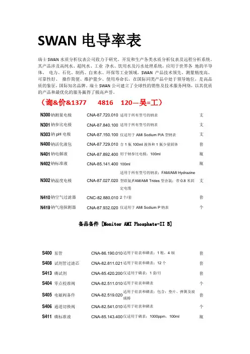
(询&价&1377 4816 120—吴=工)N300钠测量电极CNA-87.720.010适用于所有型号的钠表支N301钠参比电极CNA-87.840.100适用于所有型号的钠表支N303钠pH电极CNA-87.150.100仅适用于AMI Sodium P/A型钠表支N400钠活化液包CNA-87.729.010含1瓶100ml液体和1瓶少量固体套N401钠电解液CNA-87.892.400用于钠参比电极;100ml瓶N402钠标准液CNA-85.141.400100ml瓶N302钠温度电极CNA-87.027.020适用于所有型号的钠表;FAM/AMI Hydrazine型联氨;FAM/AMI Trides型余氯;带0.8米固定电缆支N410钠空气过滤器CNC-82.880.0102个/套套N419钠气泡探测器CNA-87.932.020仅适用于AMI Sodium P钠表个备品备件 [Monitor AMI Phosphate-II B]S400泵管CNA-86.190.010适用于硅表和磷表;1粗,4细套S408试剂管过滤芯CNA-82.811.021适用于硅表和磷表;12个套S413磷试剂CNA-85.420.200仅适用于磷表;1套/月套S404零点校准阀CNA-82.511.010适用于硅表和磷表个S405电磁阀备件CNA-82.519.020适用于硅表和磷表;包含:垫片、弹簧及玻璃棒套S406通道切换阀CNA-82.541.010适用于硅表和磷表个S411磷标准液CNA-85.143.400仅适用于磷表;1000ppm,100ml瓶S416试剂管CNA-86.190.011适用于硅表和磷表;4根,含试剂管过滤头套S417虹吸管、排气管CNA-86.190.012适用于硅表和磷表;5根套S419通道切换阀管路CNA-86.190.014适用于硅表和磷表;6根套。
热工班一直以来都以建设学习型班组为目标,为提高化学仪表方面的总体技术水平,热工班于4月26日下午请来SW AN厂家的技术人员,在炉内取样间组织了一次SW AN仪表的现场培训。
滨海电厂的SW AN仪表主要用在汽水取样监测分析系统,常用的仪表有硅表、磷表、钠表、氧表、电导表、pH计等。
这次培训的场地不再是培训教室,而是炉内取样间;讲义也不再是说明书,而是现场正在工作中的各类仪表。
厂家技术人员逐一介绍了各种仪表的基本原理,并以实际的磷表等为例,按其样水流程介绍了整个过程中可能引起仪表故障的问题及解决方案。
热工班的师傅们也抓住这次难得的机会提出了工作中产生的各种疑问:“硅表的量程是0-1000,可是我们正常的使用范围远远小于这个量程,会不会影响精确度?”,“钠表的钠电极活化时间应该是多少?”……对于这些问题,厂家都一一给出详细的解答。
汽水取样监测分析主要用于保证水、汽质量符合标准,防止设备腐蚀、结垢,对发电机组安全经济运行起着十分重要的作用。
通过这次培训,让热工班的师傅们对SW AN的仪表有了更深入的了解,也更有信心做好仪表的日常维护工作。

SWAN AMU 电导率培训教材SWAN公司在线电导率表培训文件瑞士SWAN公司中国代表处北京欧林特技术咨询有限公司(一)爱护规程每两个月(二)电导率表测量原理在测量水溶液的导电能力时,往往用电阻的倒数——电导来描述,或用电阻率的倒数——电导率来表示。
在导电的过程中,水溶液所出现出的电阻特性也符合电阻的定义。
按照欧姆定律,在水温一定的情形下,水的电阻值R 与电极的垂直截面积 A 成反比,与电极间的距离L 成正比,如下式:R= p・L/A其中p为电阻率,或称比电阻。
电阻的单位为欧姆(欧,代号Q),或用微欧(^Q), 1Q =106^Q; 电阻率的国际制(SI)单位为欧米(◎• m)。
如果电极的截面积A做成1cm2,两电极间的距离L为1cm,那么电阻值就等于电阻率。
电导率变送器电导率电极操作试剂及标液的配置:配制钠表校准所需标液(100ppb, lOOOppb)钠表可做一点或两点校准,其浓度可在10-2000ppb间任意选择。
随表配有100ml1000ppm的母液,配制时稀释即可。
预备1000ml100%纯度二异丙胺。
参比电极电解液钠表参比电极电解液为2.0M的KCl,随表配有100 ml,用完后用户可自行配制或从SWAN公司订购厂YMessages (错误信息)外表按键:所有AMI 型外表的按键均由 S 000 四个按键组成的功能是打开一个菜单或者确认输入;的功能是退出一个菜单或命令,或者返回到上一级菜单; E3込]的功能是向下或向上移动菜单,或者减小或增加数字。
外表菜单:AMI Sodium P 的菜单由 Messages 信息)、Diagnostics (诊断)、Mainten ance 爱护)、Operation 操作)和Installation (安装)五个主菜单组成。
菜单介绍Messages (错误信息)Pending Errors 1.1 (未确认故障)Message List 1.2(故障列表)2. Diagnostic (诊断)Designation AMU PowerconSensorsp.(箱体温度)222.1Iden tificati on(出厂检测)(诊断)Factory TestFront End (前端板)Operati ng Time (运行时刻)Cond. Sen sor (电导率电极)Miscellaneous (其他)In strume nt(外MotherboardYears (年)Days (天) Hours (时)Curre nt ValuRaw Value Cal. HistorCase TemSample ID (样水名称) 2.3.1Calibrati on(校准)3.1*Alarm Relay(继电器报警)3.Sample (样水)I/O StateTemperature温度)PtIOOOSample flow(样水流量)Raw valueAlarm Relay(报警继电器)241 Relay1/2(继电器1/2)(输入输出状态)In put (输入)Signal Output1/2(信号输出1/2)In terface Protocol(协议)(串口)Baud rate(波特率)3.Mai ntenan ce(爱护)2.1Maintenance(爱护) Simulatio n (模拟)Set Time (设置时刻)Relay1/2 Signal output1/2(模拟输出) 3.3*4. Operatio n (操作)数)4.1.1Sen so^S 电极)*Filter Time Con st.(过滤时刻常Hold after Cal.(校准延时)4.1.2depe nds on sett ings inum (钠报警)431.1 -Alarm RelayAlarm Sodi(报警继电器)Alarm pH(pH 报警)Operation (操作)4.3.1.2 Relay Con tacts(继电器接点)Relay1/2 In put Limit Value‘ or Setpointor Timermenu 5:1 nstallati onLogger3.25」nstallatio n(安装)r1.1*Y电池常数5.1.2.1*/ Sensorsction 温度修正5.1.2.2*h 电缆长度5.1.2.3不补偿系数补偿s 中性水Log Interval(采集间隔)431Clear Logger(清除数据采集4.Flow(流量)None 5.Sen sor parameters(电极参数)Temp. comp.Q-FlowCell ConstantTemp. CorreCable LengtComp.N oneCoefficientNeutral saltSignal outputs(信号输出)loop (电流环)Fun cti on (功Sig nal output1/2 Curre nt [(信号输出1/2)m1(钠报警 1) 531.1um2(钠报警 2) 531.2Alarm RelaySample Flo w (样水流量)5.3.1.4(报警继电器)Sample Te mp.(样水温度)5.3.1.p.hi.(箱体温高)5.3.1.6p.low (箱体温低)5.3.1.6water 高纯水Strong acids强酸Strong bases强碱Ammonia, Eth.am. 氨乙醇氨Morpholi ne吗啉Scali ng (范Alarm SodiuAlarm SodiAlarm pH(pH 报警)5.3.1.3Case TemCase TemIn stalla Fun cti on(功能)(安装) Relay Con tacts (参数)gs(限位/设置)5.341uts(信号输出)5.342rol(输出操纵)5.3435.3445.3.4.5Relay 1/2 Parameter(继电器)Limit/settin厂Active(激活)V- Sig nal outp In put Output/Co nt(输入)Fault (故障)Delay(延迟)Lan guage (语言) 5.4.1 Set defaults(复原出厂设置) 5.4.2Protocol (协议) In terfaceMiscellaneous Load Firmware (更新软件) 5.4.3 (其他)Password (密码)5.4.4Sample ID (样水点)5.4.5Device Address 设备地址 (串口)Baud Rate / ID No. Local Operation / Parity外表设置 时刻设置Mai nte nance — Set Time (3.3) 2、电极设定电池常数 Installation — Sensors —Sensors parameters —Cell Constan t 温补系数 Installation — Sensors —Sensors parameters —Temp. Corre ction电缆长度 Installation — Sensors —Sensors parameters —Cable Lengt h 3、信号输出设置第一路输出:Operati on — Signal Outputs — Signal Output 1 — Range low (低 限)、Range high (高限)第二路输出:Operation — Signal Outputs — Signal Output 2 — Range low (低 限)、Range high (高限)外表校准无需校准。

AMU pH/RedoxVersion 3.50 and laterA-96.250.441 / 060923O p e r a t o r ’s M a n u a lSWAN sets the StandardCustomer SupportSWAN and its representatives maintain a fully trained staff of technical specialists around the world. For any technical question, contact your nearestSWAN representative, or the manufacturer:SWAN ANALYTISCHE INSTRUMENTE AGTuricaphonstrasse 298616 RiedikonSwitzerlandInternet: www.swan.chE-mail: support@swan.chDocument StatusTitle:AMU pH/Redox Operator’s ManualID:A-96.250.441Revision Issue00September 2006© 2006, SWAN ANALYTISCHE INSTRUMENTE AG, Switzerland, all rights reserved Information contained in this document is subject to change without notice.AMU pH-RedoxAMU pH-RedoxA-96.250.441 / 0609231AMU pH-RedoxTable of Contents1.Safety Instructions1.1Warning Notices. . . . . . . . . . . . . . . . . . . . . . . . . . . . . . . . 31.2General Safety Regulations. . . . . . . . . . . . . . . . . . . . . . .42.Product Description2.1Description of the System . . . . . . . . . . . . . . . . . . . . . . . . 52.2Technical Data. . . . . . . . . . . . . . . . . . . . . . . . . . . . . . . . . 62.3Swansensor pH and Redox. . . . . . . . . . . . . . . . . . . . . . . 82.4Swansensor pH AY and Redox AY . . . . . . . . . . . . . . . . . 82.5Swansensor pH SI and Redox SI . . . . . . . . . . . . . . . . . . 82.6Swansensor pH FL and Redox FL. . . . . . . . . . . . . . . . . . 82.7Software. . . . . . . . . . . . . . . . . . . . . . . . . . . . . . . . . . . . . . 92.7.1Display. . . . . . . . . . . . . . . . . . . . . . . . . . . . . . . . . . . . . 92.7.2Menu Navigation Keys. . . . . . . . . . . . . . . . . . . . . . . . . 102.7.3Software Structure. . . . . . . . . . . . . . . . . . . . . . . . . . . .113.Installation3.1Installation Checklist . . . . . . . . . . . . . . . . . . . . . . . . . . . . 123.2Mounting of the Instrument . . . . . . . . . . . . . . . . . . . . . . . 133.3Connection Schemes. . . . . . . . . . . . . . . . . . . . . . . . . . . . 143.4Power Supply. . . . . . . . . . . . . . . . . . . . . . . . . . . . . . . . . . 163.5Relay Contacts. . . . . . . . . . . . . . . . . . . . . . . . . . . . . . . . . 163.5.1Alarm Relay . . . . . . . . . . . . . . . . . . . . . . . . . . . . . . . . . 163.5.2Relay Contacts 1 and 2 . . . . . . . . . . . . . . . . . . . . . . . . 163.6Signal Outputs1 and 2. . . . . . . . . . . . . . . . . . . . . . . . . . . 163.7Input. . . . . . . . . . . . . . . . . . . . . . . . . . . . . . . . . . . . . . . . . 163.8Sensor . . . . . . . . . . . . . . . . . . . . . . . . . . . . . . . . . . . . . . . 173.9Installation of Sensors . . . . . . . . . . . . . . . . . . . . . . . . . . . 173.10Interfaces. . . . . . . . . . . . . . . . . . . . . . . . . . . . . . . . . . . . . 193.10.1RS232 . . . . . . . . . . . . . . . . . . . . . . . . . . . . . . . . . . . . . 193.10.2Profibus (optional) . . . . . . . . . . . . . . . . . . . . . . . . . . . .19AMU pH-RedoxAMU pH-Redox2A-96.250.441 / 0609234.Instrument Setup . . . . . . . . . . . . . . . . . . . . . . . . . . . . 215.Operation . . . . . . . . . . . . . . . . . . . . . . . . . . . . . . . . . . . 216.Maintenance (Quality assurance)6.1Maintenance Table. . . . . . . . . . . . . . . . . . . . . . . . . . . . . . 226.2Cleaning of Electrodes. . . . . . . . . . . . . . . . . . . . . . . . . . . 236.3Longer stop of operation . . . . . . . . . . . . . . . . . . . . . . . 246.4Calibration . . . . . . . . . . . . . . . . . . . . . . . . . . . . . . . . . . . .258.Trouble Shooting8.1Error Messages . . . . . . . . . . . . . . . . . . . . . . . . . . . . . . . . 278.2Error List. . . . . . . . . . . . . . . . . . . . . . . . . . . . . . . . . . . . . .28A.AppendixA.1Program Overview . . . . . . . . . . . . . . . . . . . . . . . . . . . . . . 30A.2Program List and Explanations . . . . . . . . . . . . . . . . . . . . 33Default Values . . . . . . . . . . . . . . . . . . . . . . . . . . . . . . . . .50B.Material Safety Data SheetsB.1Buffer pH 4. . . . . . . . . . . . . . . . . . . . . . . . . . . . . . . . . . 53B.2Buffer pH 7. . . . . . . . . . . . . . . . . . . . . . . . . . . . . . . . . . 56B.3Buffer pH 9. . . . . . . . . . . . . . . . . . . . . . . . . . . . . . . . . . 59B.4Buffer ORP. . . . . . . . . . . . . . . . . . . . . . . . . . . . . . . . . .62C.RS232 InterfaceC.1Connection of the Communication Cable. . . . . . . . . . . . . 66C.2Configuration of the AMU Transmitter . . . . . . . . . . . . . . . 67C.3HyperTerminal Configuration on the PC . . . . . . . . . . . . . 68C.4Functions of the AMU RS232 Interface . . . . . . . . . . . . . . 72C.4.1Logger Download. . . . . . . . . . . . . . . . . . . . . . . . . . . . . 72C.4.2Log download . . . . . . . . . . . . . . . . . . . . . . . . . . . . . . . 73C.4.3Clear Logger . . . . . . . . . . . . . . . . . . . . . . . . . . . . . . . . 75C.5Firmware Upload . . . . . . . . . . . . . . . . . . . . . . . . . . . . . . .76D.Index . . . . . . . . . . . . . . . . . . . . . . . . . . . . . . . . . . . . . . . .78AMU pH-RedoxSafety InstructionsA-96.250.441 / 06092331.Safety InstructionsGeneralThe instructions included in this section explain the potential risks associated with instrument operation and provide important safety practices designed to minimize these risks.If you carefully follow the information contained in this section, you can protect yourself from hazards and create a safer work environment.More safety instructions are given throughout this manual, at the respective locations where observation is most important.Strictly follow all safety instructions in this publication.Target audienceOperator:Qualified person who uses the equipment for its intended purpose.Instrument operation requires thorough knowledge of applications, instrument functions and software program as well as all applicable safety rules and regulations.Operator’s Manual Loca-tionThe AMU Operator’s Manual shall be kept in proximity of the instrument.1.1Warning NoticesThe symbols used for safety-related notices have the following significance:WARNING SymbolsWARNINGGenerally, the triangular warning symbol indicates the possibility of personal injury or even loss of life if instructions are not followed, e.g.electrical shock hazardATTENTION SymbolsATTENTIONThe attention symbol indicates the possibility of equipmentdamage, malfunctions or incorrect process results if instructions are not followed.AMU pH-RedoxSafety Instructions4A-96.250.441 / 0609231.2General Safety RegulationsLegalRequirements The user is responsible for proper system operation according to all local, state and federal laws that may apply. All precautions must be followed to ensure safe operation of the instrument.Spare PartsandDisposables Use only official SWAN spare parts and disposables. If other parts are used during the normal warranty period, the manufacturer’s warranty is voided.ModificationsModifications and instrument upgrades shall only be carried out by an authorized Service Technician. SWAN will not acceptresponsibility for any claim resulting from unauthorized modification or alteration.Electrical shock hazardWARNINGIf proper operation is no longer possible, the instrument must be disconnected from all power lines, and measures must be taken to prevent inadvertent operation. To prevent from electrical shock, always make sure thatthe ground wire is connected.Service shall be performed by authorized personnelonly.Whenever electronic service is required, disconnectinstrument power and power of devices connected to•relay 1,•relay 2,•alarm relay.AMU pH-RedoxProduct DescriptionA-96.250.441 / 06092352.Product Description2.1Description of the SystemThis instrument is applicable for the measurement of the pH respectively ORP value in water.ApplicationrangepH and redox (ORP) is measured in many different applications: swimming pools waste waterhigh purity waterpower plants (steam, condensate) industryDepending on the application, different electrode types and flow cells/fittings are needed.Measuring PrinciplepH: The electrode consists of a pH sensitive glass electrode and a reference electrode = measuring chain. Depending on the pH value in the water, the mV value of the measuring chain changes. If both electrodes are integrated into one shaft it is a combined electrode. Reference electrodes are available with gel (Swansensor pH for potable water and swimming pools, Swansensor pH AY for waste water) or with liquid electrolyte (Swansensor pH SI for power plant cycle, Swansensor pH FL for high purity water).ORP: The electrode consists of a platinum pin and a reference electrode = measuring chain. Depending on the ORP value in the water, the mV value of the measuring chain changes. If bothelectrodes are integrated into one shaft it is a combined electrode. Reference electrodes are available with gel (Swansensor pH for potable water and swimming pools, Swansensor pH AY for waste water) or with liquid electrolyte (Swansensor ORP SI for power plant cycle, Swansensor ORP FL for high purity water).Temperature compensationpH: The pH value depends on temperature. If the temperature of the sample is not stable, we recommend to install a temperature sensor. If no temperature sensor is chosen, please program the temperature of the sample in the instrument.For high purity water applications (power plant, high purity water): Additionally to the Nernst compensation a non-linear solution compensation or linear compensation with coefficient can be chosen.ORP: Temperature compensation is not necessary.AMU pH-RedoxProduct Description6A-96.250.441 / 0609232.2Technical DataThe AMU measuring and control transmitter is used for panel installation. It has connections for a pH/ORP electrode and a Pt1000 temperature probe, and for a digital sample flow meter.Electronics case: Noryl® resinProtection degree: IP54 (front)Large backlit LC-Display,75 x 45mmDimensions: 96 x 96 x 119mm (DIN 43700)Weight: 0.45kgAmbient temperature: -10 to +50°C Limit range of operation:25 to +65°C Storage and transport: -30 to +85°C Humidity: 10 to 90% relative, non-condensing Voltage: 85 - 265 VAC, 47 - 63 Hz, or 24 VDC ±15%Power consumption:max. 7 VA Measuring rangeResolution0.00 to 14.00 pH Resolution: 0.01 pH -500 to 1500 mV Resolution: 1 mV Automatic range switching.TemperatureInput for Pt1000 type sensor (DIN class A)Measuring range: -30 to +250°C Resolution: 0.1°CTemperature compensationNernstNon-linear solution compensation for high purity water Linear with coefficient for high purity waterAMU pH-RedoxProduct DescriptionA-96.250.441 / 0609237Temperature monitoringAlarm if the transmitter temperature is higher than +65°C or lower than 0°C.Safety features No data loss after power failure, all data is saved in non-volatile memory. Over voltage protection of in- and outputs.Galvanic separation of measuring inputs and signal outputs.Alarm RelayOne potential free contact for summary alarm indication for programmable alarm values and instrument faults.Maximum load: 100mA / 50 VInput One input for potential-free contact. Programmable ‘HOLD’ or ‘OFF’ function.RelaysTwo potential-free contacts programmable as • limit switches for measuring values • controllers• timer for system cleaning with automatic hold function Maximum load: 100 mA / 50 VSignal OutputsTwo programmable signal outputs for measured values(freely scaleable, linear or bilinear) or as continuous control output (control parameters programmable).Current loop: 0/4 - 20 mA Maximum burden: 510 ΩControl Function Relays or current outputs programmable for 1 or 2 pulse dosing pumps, solenoid valves or for one motor valve. Programmable P , PI, PID or PD control parameters.Communica-tion InterfaceOptional RS485 interface with Fieldbus protocol PROFIBUS DP or Modbus, galvanically separated.Serial InterfaceRS232 for data logger download to PC with Microsoft HyperTerminal and for Firmware updates.AMU pH-RedoxProduct Description8A-96.250.441 / 0609232.3Swansensor pH and RedoxApplicationsPotable waterSwimming pools Details see data sheet.Operating Conditions0 to 50 °CMax. pressure: < 2 bar2.4Swansensor pH AY and Redox AYApplicationsWaste water Details see data sheet.Operating Conditions0 to 50 °CMax. pressure: < 2 bar2.5Swansensor pH SI and Redox SIApplicationsPower plant cycle Details see data sheet.Operating Conditions0 to 50 °C Pressure-freeFlow speed: 5 to 10 l/h2.6Swansensor pH FL and Redox FLApplicationsHigh purity water Details see data sheetOperating Conditions0 to 50 °C Pressure-freeFlow speed: 5 to 10 l/hProduct Description2.7Software2.7.1DisplayMenu navigation keys°CStatusblinking: fatal errorerrorupper / lower limit reachedupper / lower limit not yet reached control upw. / dnw.: no actioncontrol upw. / dnw.: active, dark bar indicates control intensity timertimer: timing active (hand rotating)Relay Statussample temperaturesample flowmotor valve: valve closedmotor valve: open, dark bar indicates approximate position 25TimeR1R28 l /h7.43 p ΗHOLD The Input is activated. The Signal Outputs are frozen.OFFThe Input is activated; the Signal Outputs are set to 0 (0/4 mA)RUN normal operationProduct Description2.7.2Menu Navigation KeysKeysProgram NavigationFor a detailed listing of the menu see Program Overview, p. 30to exit a menu or command (without accepting)to move back to the previous menu level to move DOWN in a menu list and to decrease digitsto move UP in a menu list and to increase digitsto open a selected sub-menu to confirm an entryExitEnterEnterExit25.0°CRUN14:10:45R1x pHR21InstallationOperation Diagnostics Maintenance Main MenuProduct Description2.7.3Software Structure1Messages Operation Maintenance Diagnostics Main Menu Menu Operation 4Subset of menuInstallation 5, but process-related. User relevant parameters that might need to be modified during daily routine. Normally password protected and used by the process-operator.Menu Messages 1Reveals pending errors as well as an event history (time and state of events that have occured at an earlier point in time).Menu Diagnostics 2Provides user relevant instrument and sample data.Menu Installation 5For initial instrument set up by SWAN authorized person, to set allinstrument parameters. Normally password protected.Menu Maintenance 3For instrument calibration, relay and signal output simulation and to set the instrument time. It is used by the service personnel.Installation1.1Message ListMessages 2.1InterfaceI/O State Sample Sensors Diagnostics 3.1SimulationMaintenanceSet Time 02.04.05 16:49:304.1LoggerRelay Contacts Operation 5.1InterfaceMiscellaneous Relay Contacts Signal Outputs InstallationInstallation3.Installation3.1Installation ChecklistCheck Instrument’s specification must conform to yourpower ratings.Installation Mount the instrument in vertical position. Displayshould be at eye level.Electrical Wiring Connect all external devices like limit switches and current loops.Connect power cord; do NOT switch on power yet!Flow cell / fitting Install flow cell / fitting.Flow cell: Ensure outlet is pressure-free.Electrode Remove protective cap. Install in flow cell/fitting.Remove plug cap. Connect the sensor(s) to theAMU transmitter. Store sensor caps for interrup-tion of operation.QV-flow: Install reference in the hole near thepanel.Fitting: Ensure fitting is water-tight.Power up Flow cell: Turn on sample flow and wait until it iscompletely filled. Switch on power.Instrument setup Flow cell: Adjust sample flow.Program all parameters for sensor and external devices(interface, recorders, etc.). Program all parame-ters for instrument operation (limits, alarms).Run-in period Let the instrument run continuously for 1 h. pH electrodecalibrationCalibrate pH electrode.ORP in potable/waste waterCalibrate ORP electrode.ORP in high purity water: Process calibration Let the electrode run in for at least 24 h.Make a valid manual measurement with a suitable ORP electrode. Compare this value to the value, indicated by the AMU. If necessary, correct.Installation3.2Mounting of the InstrumentStandard housing according to DIN 43700: 96 x 96 x 119 mmInstallation3.3Connection Schemes ArrayRear viewInstallationThe type plate for theproduct identification is on the back side of the AMU transmitter.11.431.102pH / RedoxInstallation3.4Power SupplyPower Supply ConnectorNeutralPower3.5Relay Contacts3.5.1Alarm RelayNote: Max. load 100mA / 50 VTerminal 5/63.5.2Relay Contacts 1 and 2Note: Max. load 100mA / 50 VRelay 1: Terminal 1/2Relay 2: Terminal 3/43.6Signal Outputs1 and 2Note:Max. burden 510 ΩIf signals are sent to two different receivers,use signal isolator (loop isolator).Signal Output 1: Terminal 13 (+) and 12 (-)Signal Output 2: Terminal 14 (+) and 12 (-)Current loop: 0 - 20 mA resp. 4 - 20 mA3.7InputUse only potential-free (dry contacts).Terminal: 11/10Installation3.8SensorConnect the sensor as follows:pH / ORP Sensor:Terminal 21: shielded lineTerminal 22: shieldExternal reference sensor:Terminal 23: shielded lineTerminal 24: shieldTemperature sensor Pt1000:Terminal 20: shielded lineTerminal 19: shield3.9Installation of SensorsFlow cell M-Flow Cautiously pull off rubber cap from pH/ORP electrode tip. Fragile! Handle with care!Insert pH/ORP electrode into one of the PG threads and fasten hand-tight.Take off plug cap. Connect to sensor cable.Store the plug and rubber cap for interruptions of operation.The temperature sensor is already mounted and connected to the cable.Flow cell QV-Flow We recommend to mount the pH/ORP SI respectively Reference FL electrode in the insert near the panel. Flow cell, view from aboveElectrode Cautiously pull off rubber cap from pH/ORP electrode tip.Insert pH/ORP electrode into the opening (see above) and fastenhand-tight.Take off plug cap. Connect to sensor cable.Store the plug and rubber cap for interruptions of operation.InstallationTemp. sensor The sensor is already mounted and connected to the cable.Reference electrode The reference electrode (Swansensor pH SI, Swansensor ORP SI, Swansensor FL) is delivered with an electrolyte tube, which is alreadymounted and filled. The sealed electrolyte bottle is also included in delivery.- Cautiusly take of the rubber cap from electrode tip. Make sure that the black cap at the tip of the electrode is fastened hand-tight.- The reference electrode has to be free of air bubbles: Hold the electrode, tip downwards, in one hand and hold the electrolyte tube with the other hand straight above the the electrode. Shake theelectrode slightly in an angular position to release air, which might be inside. Release air bubbles in the electrolyte tube by knocking on it.- Insert the electrode into the flow cell and fasten hand-tight.- Cut off the tip of the electrolyte bottle. Take the plug out of the electrolyte tube. Put the electrolyte bottle firmly on the tube.- Mount the electrolyte bottle in the click holder (see 2.3 Instrument overview, p. 11).- Puncture the electrolyte bottle to allow pressure equilibration.- Take off plug cap. Connect to sensor cable. Store caps.UNIDIP fitting Please refer to the manual of the UNIDIP fitting how to install the pH/ORP electrode and the temperature sensor in detail. Ensure that all sur-faces and o-rings are clean. If mounted correctly, the UNIDIP fitting is tight. No water is allowed inside the UNIDIP fitting. Otherwise the cables corrode. If you use an UNIDIP Rinsematic, make sure the nozzles face the pH/ORP sensor.Temperature sensor and electrodes: Fragile! Handle with care!Installation3.10Interfaces3.10.1RS232The interface RS232 is on the backside ofthe AMU transmitter.For connecting the communication cable and the configuration(using RS232 for data logger download to PC and for firmwareupdates) see RS232 Interface, p. 663.10.2Profibus (optional)The interface RS485,galvanically separated.To connect several instruments by means of a network, use a free-cable end PROFIBUS cable. See picture below.InstallationPlease buy a free-cable end PROFIBUS cable from your local supplier.NOTE: The color of the wires might be different. Before connecting it to the transmitter, please check the corresponding data sheet.The PROFIBUS connections have to be short-circuited.The shield has the function to change or replace the transmitter without inactivating the bus connection.NOTE: Terminate bus by means of ON/OFF switch on the RS485interface only. If only one instrument is installed, or on the last instrument in a bus, the termination switch must be ON .terminationswitchInstrument Setup4.Instrument SetupSensor Check if:Power is availableSensor is installed and connected correctly.For connecting the sensor to the transmitter, see Swansensor pHand Redox, p. 8Establish Sample Flow 1Check if sample is available.2Assure pressure-free sample outflow.3Open sample flow. (Wait until flow cell is completely filled.) 4If applicable, check flow cell for leaks.5Connect the instrument to power.6Adjust sample flow.7Set all necessary parameters in Installation, Sensors 5.1.- Flow: Set if you use the Q-flow cell (with Swan flow meter)- Parameter: Set measuring parameter pH or ORPSensor check: No.- Temperature: Set if a temperature sensor has been connected.If no, program the temperature of the sample (default temp.)If yes, you can set a temp. correction, if necessary.- Temperature compensation: Only for pH, not for ORP.- Standard solution(s): Program the buffer values (pH buffer table)or the ORP calibration solution.8Program all parameters for external devices (interface,recorders, etc.). Program all parameters for instrumentoperation (limits, alarms, etc.)9Let run in for 1 h. Correct if necessary, or calibrate. SeeInstallation check list.5.OperationTo have a general survey of the menu 4: Operation, see ProgramOverview, p. 30. For explanations see Program list andexplanations.You can modify:The Filter Time Constant and the time for Hold after Calibration for the sensorThe Settings for the Relay Contacts and the Input.Maintenance (Quality assurance)6.Maintenance (Quality assurance)This section describes the activities intended to retain theinstrument in, or to restore it to a state in which it maintains the required or specified performance.6.1Maintenance TableSwansensor pH / Swansensor Redox (ORP)Swansensor pH AY / Swansensor Redox (ORP) AYSwansensor pH SI or FLSwansensor Redox (ORP) SI or FLTwice per month Calibrate electrode. Ensure buffers are not expired. If necessary, replace electrode.YearlyIf necessary, clean electrode.Twice per month Clean electrode.MonthlyCalibrate electrode. Ensure buffers are not expired. If necessary, replace electrode.Weekly Check level in electrolyte bottle. If necessary, change bot-tle.Monthly Calibrate electrode.All 3 monthsOpen cap of reference electrode slightly and let flow out 5 ml of electrolyte. Fasten cap hand-tight.Weekly Check level in electrolyte bottle. If necessary, change bot-tle.Monthly If necessary, correct electrode.All 3 monthsOpen cap of reference electrode slightly and let flow out 5 ml of electrolyte. Fasten cap hand-tight.Maintenance (Quality assurance)6.2Cleaning of ElectrodesCleaningSwansensor pH and pH AYTake the electrode out of the flow cell. If necessary wipe the electrode shaft and the green tip cautiously with a soft, clean, and damp papertissue.Remove grease with a tissue moistured with alcohol (caution! Inflammable!).If the electrode is very dirty, put it into 1% diluted hydrochloric acid for roughly 1 min. Caution! Etching!!Afterwards rinse the electrode thoroughly with clean water.Remount in the flow cell again.Let the electrode run-in for 1 h before the first calibration.Swansensor ORP and ORP AY Take the electrode out of the flow cell. If necessary, wipe off dirt cautiously with a soft, clean, and damp paper tissue.Dull platinum surfaces indicate a contamination. Clean the electrode byputting it into the calibration solution or in 1% diluted hydrochloric acid for some minutes. Caution! Both solutions are etching!Afterwards rinse the electrode thoroughly with clean water.Remount in the flow cell again.Let the electrode run-in for 1 h before the first calibration.Swansensor pH SI and pH FL If necessary, wipe the green tip of the electrode cautiously with a soft, clean, and damp paper tissue. If necessary, remove grease with atissue, moistured with alcolhol (Caution! Inflammable!). Do not insertinto acidsReference electrode: Open the cap (diaphragm) at the tip of theelectrode slightly and let flow out some ml of electrolyte. Caution! KCL is corrosive! Fasten cap hand-tight again.Afterwards rinse the electrode thoroughly with high purity water.Remount in the flow cell again.Let the electrode run-in for 1 h before the first calibration.Swansensor ORP SI and ORP FL If necessary, wipe the tip of the electrode cautiously with a soft, clean, and damp paper tissue. Do not insert into acidsReference electrode: Open the cap (diaphragm) at the tip of theelectrode slightly and let flow out some ml of electrolyte. Caution! KCL is corrosive! Fasten cap hand-tight again.Afterwards rinse the electrode thoroughly with high purtiy water.Remount in the flow cell again.Let the electrode run-in for at least 24 h before the first correction.6.3Longer stop of operationStop sample flow.Shut off power of the instrument.Take off the cable of the electrode(s) and put the plug cap on it.Take the electrode(s) out of the flow cell/fitting and rinse with cleanwater. Fill 3.5 molar KCl (if not available: water) into the rubber capand place it on the tip of the electrode. Never store combined pH/ORP electrodes, respectively reference electrode, dry!Store the electrode(s) with tip pointing downwards in a frost-protected room.Maintenance (Quality assurance)6.4CalibrationProcess pH /ORP Use a suitable, high quality electrode and instrument to determine thesample value. Ensure, the electrode is calibrated correctly! Enterthis value under Process value in menu Process pH/ORP .Possible er-ror message Offset error:Last calibration wrong.Electrode old or dirty.Cable wet.EnterProcess pH Current Value 7.78 pH Offset x mV Save<Enter>Process Value 7.70 pH 3.1.1.13.1.1.1Process pH Current Value 7.70 pH Offsety mVpressEnter3.1.1.1Process pH Current Value 7.70 pH Offset y mV Process Value 7.70 pH EnterProcess pH Offset x mV Save <Enter>3.1.1.1EnterCurrent Value 7.78 pH 3.1SimulationMaintenanceSet Time 01.01.05 16:30:003.1.1Standard pHCalibration EnterEnter correct value with arrow keys.。

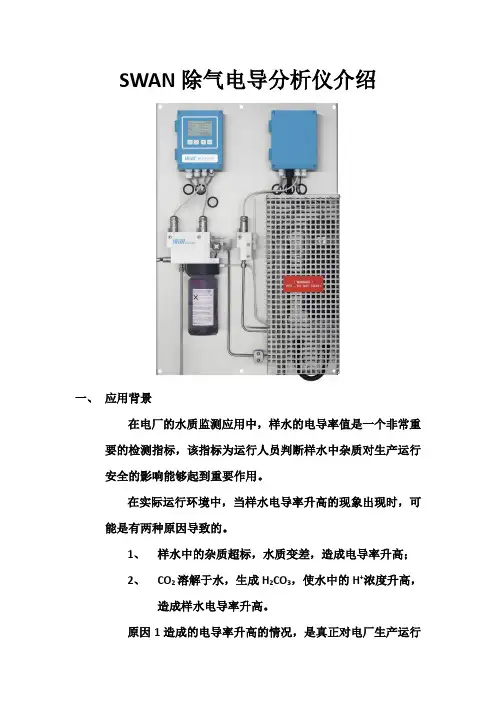
SWAN除气电导分析仪介绍一、应用背景在电厂的水质监测应用中,样水的电导率值是一个非常重要的检测指标,该指标为运行人员判断样水中杂质对生产运行安全的影响能够起到重要作用。
在实际运行环境中,当样水电导率升高的现象出现时,可能是有两种原因导致的。
1、样水中的杂质超标,水质变差,造成电导率升高;2、CO2溶解于水,生成H2CO3,使水中的H+浓度升高,造成样水电导率升高。
原因1造成的电导率升高的情况,是真正对电厂生产运行安全造成重大隐患的问题,需要运行人员立刻进行处理。
而对于原因2造成的电导率升高的情况,样水溶解的CO2不会对机组安全运行产生重大影响。
因此,如何判断导致样水电导率升高的原因,就成为电厂在线水质监测和机组安全运行的重要课题。
二、除气电导分析仪设计原理及工作方式SWAN除气电导分析仪采用加热除气的原理,通过内置的气压计,计算出当地的沸点,将样水加热到低于当地沸点2℃,在去除样水中溶解的CO2的同时,保证样水不沸腾,避免因沸腾造成的水样浓缩改变样水水质。
样水流路:进水管→比导电极→树脂柱→阳导电极→冷却器→加热器→除气电导电极→排水管。
在除气电导分析仪的水路中,进入冷却器的样水与经过加热器加热完成脱气过程的水在冷却器内进行热交换,以此达到预热来水,冷却出水,增加热效率,减少能源浪费和排水的高温污染的目的。
三、除气电导分析仪的特点●自冷却——独特设计样水自身作为冷却水,省去另加冷却水。
●断样、超温保护:根据流量计和温度计的测量值自动判断给加热器送电还是断电。
●配备气压计:根据气压计在就地测量的气压值,自动选择除气最佳的样水温度(低于沸点2摄氏度)防止因样水沸腾蒸发浓缩,水质发生变化。
●可同时测量比导、阳导、除气阳导、pH值和氨溶度5个参数,可自行设置分屏显示各个参数的测量值。
●监测样水流量和温度,并给出报警。
●根据被测水质自动选择不同的非线性温补曲线。
●树脂柱自动除气。
●树脂失效报警。
●树脂预冲洗(选项),使仪表迅速投入正常工作。
COPAR SILICA 硅酸盐连续测定仪安装启动步骤检查工作电压是否符合仪表额定值!不要开启电源,按照2.7章节所讲的去做后!安装位置(2.1):选择一个方便调整和方便打开仪表前门的地方,仪表位置必须满足以下连接要求:- 交流电源出口接地,至少100~230VAC,50/60Hz/85 VA。
- 每通道样水管线(4x6 mm)满足至少10 ml/min的流速和0.3 - 3 bar(4 - 43 psi)的气压。
- 废水管线(14x20 mm (1/2"))常压排放,2 - 4通道仪表。
安装(2.4):- 垂直安装仪表。
- 连接样水管路、安全通道、废水线路。
- 安装离子交换柱电气连接(2.5)- 连接所有外设,如限位开关、电流回路和打印机等。
- 连接电源线,不要接通电源。
泵管(2.6)- 安装压力棒,将泵管紧压在泵体上。
样水流(2.7)- 检查样水是否无滴漏,管路是否通畅(样水中不能有污物)。
- 打开样水控制阀。
调整流量大小。
样水最终必须连续地从废水孔排出。
标准(2.7)- 用优质(无硅)水彻底清洗标准瓶。
- 根据你的需要配制标准硅溶液,最好直接在标准瓶内配置。
- 安装试剂瓶。
试剂(2.7)- 根据配方,用有标签的试剂桶配制试剂。
- 根据颜色代码将试管连接到分配器(在泵的正下方)。
- 根据颜色代码将试管放在试剂桶内。
兰色钼酸红色硫酸无色草酸黑色还原剂(硫酸亚铁铵)接通电源(2.7)- 接通电源。
- 试管被自动注满,同时反应试管和光度计被加热到运转温度。
仪表设置(4 & 5)- 设置外接设备的所有参数(界面、打印机、记录器和其它选项)。
- 设置仪表运转参数(自动校准、限位、打印输出和记录器)。
2 安装2.1 安装要求选择一个便于靠近仪表和试剂桶的地方,仪表位置必须满足以下连接要求:电源:100~230VAC+15%,85VA进水口:适配4 x 6 mm FEP管的Serto管2支到4支排水口:1/2" (14 x 20 mm) 软管,它有足够的容量可以在环境大气压下自由排放警告:仪表中所有连接必须遵循章节2.5和附录中提到的最小化系统规范。
ANALYTICAL INSTRUMENTSSWAN公司在线AMU电导率表培训文件瑞士SWAN公司中国代表处北京欧林特技术咨询有限公司(一)测量原理在测量水溶液的导电能力时,往往用电阻的倒数——电导来描述,或用电阻率的倒数——电导率来表示。
在导电的过程中,水溶液所呈现出的电阻特性也符合电阻的定义。
根据欧姆定律,在水温一定的情况下,水的电阻值R与电极的垂直截面积A成反比,与电极间的距离L成正比,如下式:R=ρ·L/A其中ρ为电阻率,或称比电阻。
电阻的单位为欧姆(欧,代号Ω),或用微欧(μΩ),1Ω=106μΩ;电阻率的国际制(SI)单位为欧米(Ω·m)。
如果电极的截面积A做成1cm2,两电极间的距离L为1cm,那么电阻值就等于电阻率。
(二)仪表结构PAM 电导率变送器B-Flow 70 流通池Sensor UP-CON测量电极(三)操作同时按下PAR和PGR键,进入编程状态,第一个编程序号P0.0在屏幕上出现。
按PGR键,屏幕上编程序号以十倍数量级变化(P0.0 → P1.0→ P2.0等)。
按PAR键,屏幕上编程序号以一个数量级变化(P0.0 →P0.1→ P0.2等)。
改变程序值:用箭头键改变程序值。
用ENTER键确认新数值,或用ESCAPE键退出这一设置。
按PGR或PAR键,出现另一个编程项。
用键退出编程方式。
设置仪表:(1)P1.0:输出功能选择1,模拟输出对应电导率测量值。
(2)P1.1:程序值选择0表示模拟信号为0-20mA, 1=4-20mA (3)P1.2:模拟输出0/4mA对应的测量值(输出量程下限)(4)P1.3:模拟输出20mA对应的测量值(输出量程上限)(四)校准无需校准。
斯旺电导表说明书(最新版)目录1.斯旺电导表说明书概述2.斯旺电导表的主要特点3.斯旺电导表的使用方法4.斯旺电导表的维护与保养5.斯旺电导表的安全注意事项6.斯旺电导表的售后服务与联系方式正文一、斯旺电导表说明书概述斯旺电导表是一款高精度、高稳定性的电导测量仪器,适用于各种工业、科研和实验室等领域的电导值测量。
本说明书旨在帮助用户更好地了解和操作斯旺电导表,确保测量结果的准确性和设备的安全性。
二、斯旺电导表的主要特点1.高精度:斯旺电导表采用先进的测量技术和高精度传感器,能够实现高精度的电导值测量。
2.高稳定性:斯旺电导表具有良好的抗干扰性能,能够在各种复杂的电磁环境中保持稳定的测量结果。
3.宽测量范围:斯旺电导表具备较宽的测量范围,能够满足不同场景下的电导值测量需求。
4.便捷的操作:斯旺电导表采用智能化设计,操作简单便捷,用户只需按照提示进行操作即可完成测量。
5.良好的安全性:斯旺电导表具有完善的安全保护措施,能够在保证测量结果准确的同时确保设备及人员的安全。
三、斯旺电导表的使用方法1.开机:连接电源适配器,将电源开关切换至“ON”位置,开启斯旺电导表。
2.连接测量电极:将测量电极与待测溶液连接,确保连接处密封牢固。
3.设置参数:根据待测溶液的性质,设置相应的测量参数,如温度、浓度等。
4.开始测量:按下“测量”键,斯旺电导表开始进行测量,测量过程中请勿触碰测量电极。
5.查看结果:测量完成后,斯旺电导表会自动显示测量结果,用户可根据需要查看或记录。
6.关闭设备:测量完成后,关闭电源开关,待设备完全关闭后,拔掉电源适配器。
四、斯旺电导表的维护与保养1.定期校准:为确保测量精度,建议用户定期对斯旺电导表进行校准。
2.清洁保养:使用完毕后,请将测量电极清洗干净,避免长时间浸泡在溶液中。
3.储存条件:请将斯旺电导表存放在通风干燥、避免阳光直射的环境中,避免与其他腐蚀性物品接触。
五、斯旺电导表的安全注意事项1.使用前请仔细阅读说明书,确保正确操作。