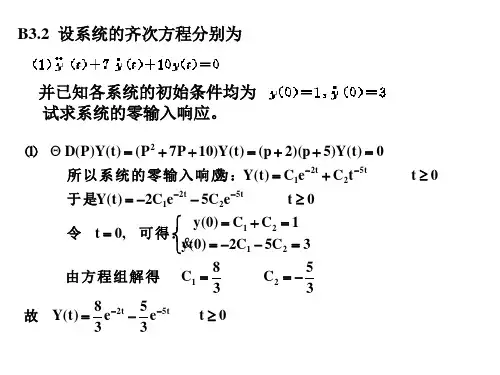
自控作业答案-第三章
- 格式:doc
- 大小:195.00 KB
- 文档页数:3
习题3-1.选择题:(1)已知单位负反馈闭环系统是稳定的,其开环传递函数为:)1(2)s )(2+++=s s s s G (,系统对单位斜坡的稳态误差是:a.0.5 b.1 3-2 已知系统脉冲响应t e t k 25.10125.0)(-=试求系统闭环传递函数)(s Φ。
解 Φ()()./(.)s L k t s ==+001251253-3 一阶系统结构图如图3-45所示。
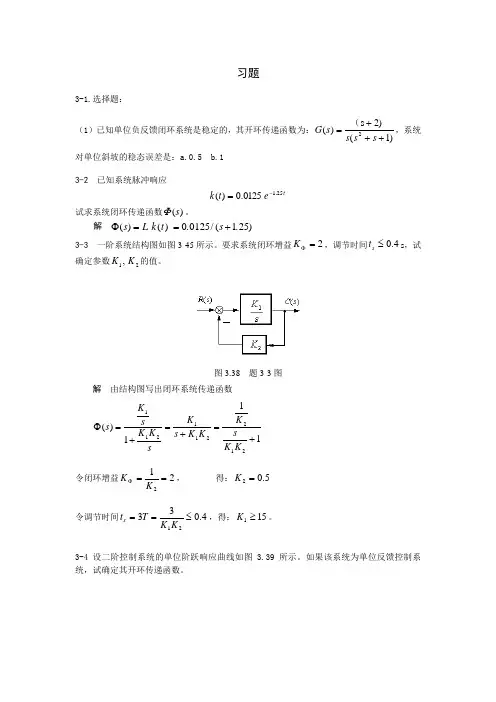
要求系统闭环增益2=ΦK ,调节时间4.0≤s t s ,试确定参数21,K K 的值。
图3.38 题3-3图解 由结构图写出闭环系统传递函数111)(212211211+=+=+=ΦK K sK K K s K sK K s K s令闭环增益212==ΦK K , 得:5.02=K 令调节时间4.03321≤==K K T t s ,得:151≥K 。
3-4 设二阶控制系统的单位阶跃响应曲线如图 3.39 所示。
如果该系统为单位反馈控制系统,试确定其开环传递函数。
图3.39 题3-4图 解:由图2.8知,开环传递函数为3-5 设角速度指示随动统结构图如图3-40所示。
若要求系统单位阶跃响应无超调,且调节时间尽可能短,问开环增益K 应取何值,调节时间s t 是多少?图3-40 题3-5图解:依题意应取 1=ξ,这时可设闭环极点为02,11T -=λ。
写出系统闭环传递函数Ks s Ks 101010)(2++=Φ 闭环特征多项式20022021211010)(⎪⎪⎭⎫ ⎝⎛++=⎪⎪⎭⎫ ⎝⎛+=++=T s T s T s K s s s D 比较系数有 ⎪⎪⎩⎪⎪⎨⎧=⎪⎪⎭⎫ ⎝⎛=K T T 101102200 联立求解得 ⎩⎨⎧==5.22.00K T 因此有 159.075.40''<''==T t s3-6 图3.41所示为某控制系统结构图,是选择参数K 1和K 2,使系统的ωn =6,ξ=1.3-7 已知系统的特征方程,试判别系统的稳定性,并确定在右半s 平面根的个数及纯虚根。
3-1(1) )(2)(2.0t r t c= (2) )()()(24.0)(04.0t r t c t c t c=++ 试求系统闭环传递函数Φ(s),以及系统的单位脉冲响应g(t)和单位阶跃响应c(t)。
已知全部初始条件为零。
解:(1) 因为)(2)(2.0s R s sC =闭环传递函数ss R s C s 10)()()(==Φ 单位脉冲响应:s s C /10)(= 010)(≥=t t g单位阶跃响应c(t) 2/10)(s s C = 010)(≥=t t t c(2))()()124.004.0(2s R s C s s =++ 124.004.0)()(2++=s s s R s C 闭环传递函数124.004.01)()()(2++==s s s R s C s φ 单位脉冲响应:124.004.01)(2++=s s s C t e t g t 4sin 325)(3-= 单位阶跃响应h(t) 16)3(61]16)3[(25)(22+++-=++=s s s s s s Ct e t e t c t t 4sin 434cos 1)(33----=3-2 温度计的传递函数为11+Ts ,用其测量容器内的水温,1min 才能显示出该温度的98%的数值。
若加热容器使水温按10ºC/min 的速度匀速上升,问温度计的稳态指示误差有多大?解法一 依题意,温度计闭环传递函数11)(+=ΦTs s 由一阶系统阶跃响应特性可知:o o T c 98)4(=,因此有 min 14=T ,得出 min 25.0=T 。
视温度计为单位反馈系统,则开环传递函数为Ts s s s G 1)(1)()(=Φ-Φ= ⎩⎨⎧==11v T K用静态误差系数法,当t t r ⋅=10)( 时,C T Ke ss ︒===5.21010。
解法二 依题意,系统误差定义为 )()()(t c t r t e -=,应有 1111)()(1)()()(+=+-=-==ΦTs TsTs s R s C s R s E s e C T s Ts Ts ss R s s e s e s ss ︒==⋅+=Φ=→→5.210101lim )()(lim 23-3 已知二阶系统的单位阶跃响应为)1.536.1sin(5.1210)(2.1o tt et c +-=-试求系统的超调量σ%、峰值时间tp 和调节时间ts 。
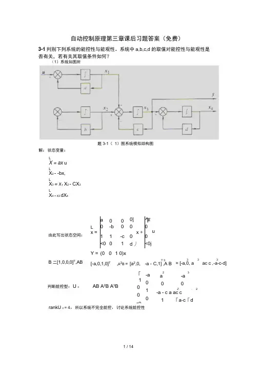
自动控制原理第三章课后习题答案(免费)3-1判别下列系统的能控性与能观性。
系统中a,b,c,d 的取值对能控性与能观性是 否有关,若有关其取值条件如何?rankU c = 4,所以系统不完全能控,讨论系统能控性a 0 0 0] 乍L-b0 0 0x =x +1 1-c 0 0<0 01 d 丿<0jY = (0 0 1 0)x[-a,0,1,0]T,A 2B = [a 2,0, -a -3 33= [-a,0, aac c ,-a -c -d]判断能控型:U cAB A 2B A 3B「1 0<0-a0 1 0 23a-a 0 02 .. 2-a - c a ac c1「a -c 「d(1)系统如图所示。
解:状态变量:L X = ax u L X 2 - -bx 2L X 3 = x 1 X 2 - CX 3 LX 4 = X3 dX 4题3-1( 1)图系统模拟结构图u由此写出状态空间: B 二[1,0,0,0]T,ABT 3C,1] ,A BrC 、r 00 1 0、 判断能观性:u 0 =CA1 1 -c 0 CA 2—2 c_a _c—b —c 03」2丄 丄2>a +ac+c2 2b +bc + c2-c °」rankU 。
= 4,所以系统不能观(2)系统如图所示。
X iy = 10 x1 -a+b' Uc=[B,AB] =Q —c —d 丿若 a-b-c-d -b=0,贝U rankU c 二 2,系统能控.U o'c iCA 丿 l _a0 b;若b = 0,则rankU 。
=2,系统能观. (3)系统如下式:fX 1C1 1 0、 *'2 1 A * X2=0-10X2+ a 0 u* 3 0 -2.<b 0」E 丿5〕=c 0d 、X 2A 丿<00 0」g解:系统如下: a解:状态变题3-1 (2)图系统模拟结构图(3)求取对角标准型,1 1 ' …-4 1 1 1 ',P-b2 d -1> P - 1-1 1 0LX = 0 -1 0X 2+<00 -2 ) 0若a =0,b = 0,系统能控. 若c = 0,d = 0 ,系统能观. 3-2时不变系统:• '-3 1 )竹1「1 <试用两种方法判别其能控性与能观性。
作业3-11,3-12,3-15.。
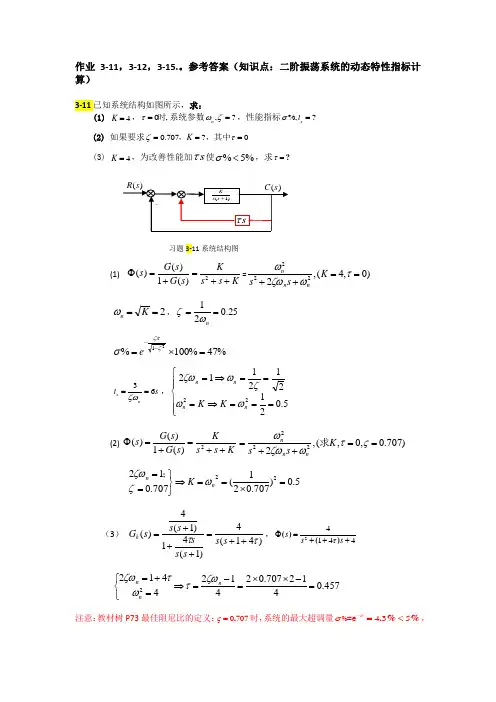
参考答案(知识点:二阶振荡系统的动态特性指标计算)3-11已知系统结构如图所示,求:(1) 4K =,0,τ=时系统参数,?n ωζ=,性能指标%,?s t σ=(2) 如果要求0.707?0K ζτ===,,其中(3) 4K =,为改善性能加s τ使%5%σ<,求τ=?习题3-11系统结构图(1) K s s K s G s G s ++=+=Φ2)(1)()(=)0,4(,2222==++τωζωωK s s nn n 2==K n ω,25.021==n ωζ %47%100%21=⨯=--ζζπσe 36s n t s ζω==,⎪⎪⎩⎪⎪⎨⎧===⇒===⇒=5.021********n n n n K K ωωζωζω (2) K s s K s G s G s ++=+=Φ2)(1)()()707.0,0,(,2222==++=ςτωζωωK s s nn n 求 5.0)707.021(707.01222=⨯==⇒⎭⎬⎫==n n K ωζζω; (3) )41(4)1(41)1(4)(ττ++=+++=s s s s s s s s G k ,24144s s s τΦ=+++()() 457.0412707.024*******=-⨯⨯=-=⇒⎩⎨⎧=+=n n n ζωτωτζω 注意:教材树P73最佳阻尼比的定义:0707ς=.时,系统的最大超调量435πσ-=<.%%%=e ,1.3调节时间最短,即平稳性和快速性最佳。
本题的启示:(1)求得原系统的超调量47σ=%%非常大,(2)为了降低超调<5%,降低了开环增益K 。
(注意:求解稳态误差时,为了提高精度,可以增大开环增益。
当设计者进行系统参数设定时,需要兼顾动静态指标) (3)为了降低超调<5%,在前向通道环节引入了微分环节。
3-12已知系统的单位阶跃响应曲线如图所示,求系统的闭环传递函数。

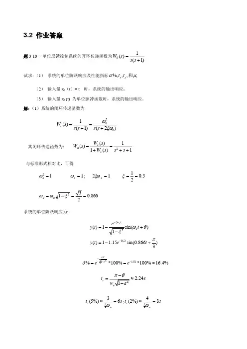
3.2 作业答案题3-10一单位反馈控制系统的开环传递函数为)1(1)(+=s s s W k试求:(1) 系统的单位阶跃响应及性能指标;,,%,μσ和s r t t (2) 输入量x r (t )= t 时,系统的输出响应;(3) 输入量x r (t) 为单位脉冲函数时,系统的输出响应。
解:(1)系统的闭环传递函数为)2()1(1)(2n nk s s s s s W ξωω+=+= 其闭环传递函数为: 11)(1)()(2++=+=s s s W s W s W k k B 与标准形式相对比,可得12=n ω 1=n ω; 12=n ξω 5.021==ξ 866.02312==-=ξωωn d 系统的单位阶跃响应为:)3866.0sin(15.11)()sin(11)(5.02πθωξξω+-=+--=--t e t y t e t y t d t n1.81%*100%*100%16.4%e e δ-==≈2.24r t s =≈s t ns 63%)5(=≈ξω;s t ns 84%)2(=≈ξωs w t df 26.72==π(5%)60.826(5%)7.26s f t u t === *(2)当输入量为t t x r =)(时,求系统的输出响应。
根据传递函数的定义,利用拉氏变换和拉氏反变换进行计算 输入量的拉氏变换为 21)(ss X r =,则 22222222222)23()21(2331)23()21(21111111111)(++-++++-+=+++-+=+++++=++=s s s s s s s s s s s s DCs s Bs A s s s s X c将上式进行拉氏反变换,等到系统的输出响应为:t e t e t t x t t c 23sin 3323cos1)(5.05.0---+-= (3) 当输入量)()(t t x r δ=时,求系统的输出响应。
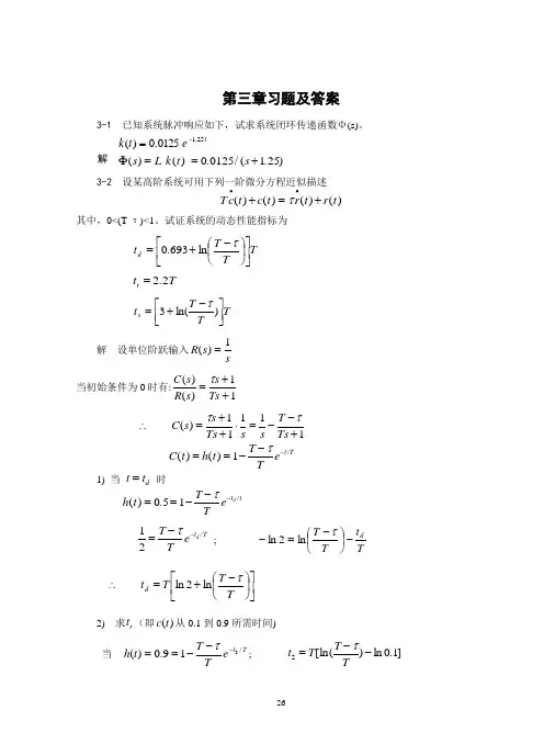
第三章习题及答案3-1 已知系统脉冲响应如下,试求系统闭环传递函数Φ(s)。
t e t k 25.10125.0)(-=解 Φ()()./(.)s L k t s ==+001251253-2 设某高阶系统可用下列一阶微分方程近似描述T c t c t r t r t ••+=+()()()()τ其中,0<(T-τ)<1。
试证系统的动态性能指标为 T T T t d ⎥⎦⎤⎢⎣⎡⎪⎭⎫⎝⎛-+=τln 693.0t T r =22. T T T t s ⎥⎦⎤⎢⎣⎡-+=)ln(3τ 解 设单位阶跃输入ss R 1)(= 当初始条件为0时有:11)()(++=Ts s s R s C τ 11111)(+--=⋅++=∴Ts T s s Ts s s C ττ C t h t T Te t T()()/==---1τ 1) 当 t t d = 时h t T Te t td ()./==---051τ12=--T T e t T d τ/ ; Tt T T d-⎪⎭⎫ ⎝⎛-=-τln 2ln ⎥⎦⎤⎢⎣⎡⎪⎭⎫ ⎝⎛-+=∴T T T t d τln 2ln2) 求t r (即)(t c 从0.1到0.9所需时间) 当 Tt e TT t h /219.0)(---==τ; t T T T 201=--[ln()ln .]τ当 Tt eTT t h /111.0)(---==τ; t T T T 109=--[ln()ln .]τ 则 t t t T T r =-==21090122ln ... 3) 求 t sTt s s eTT t h /195.0)(---==τ ∴=--t T T T s [ln ln .]τ005=-+T T T[ln ln ]τ20=+-T T T [ln]3τ3-3 一阶系统结构图如题3-3图所示。
要求系统闭环增益2=ΦK ,调节时间4.0≤s t (s ),试确定参数21,K K 的值。

3-1 设系统的微分方程式如下:(1) )(2)(2.0t r t c =&(2) )()()(24.0)(04.0t r t c t c t c =++&&&试求系统闭环传递函数Φ(s),以及系统的单位脉冲响应g(t)和单位阶跃响应c(t)。
已知全部初始条件为零。
解:(1) 因为)(2)(2.0s R s sC = 闭环传递函数ss R s C s 10)()()(==Φ 单位脉冲响应:s s C /10)(= 010)(≥=t t g单位阶跃响应c(t) 2/10)(s s C = 010)(≥=t t t c(2))()()124.004.0(2s R s C s s =++ 124.004.0)()(2++=s s s R s C 闭环传递函数124.004.01)()()(2++==s s s R s C s φ 单位脉冲响应:124.004.01)(2++=s s s C t e t g t 4sin 325)(3-= 单位阶跃响应h(t) 16)3(61]16)3[(25)(22+++-=++=s s s s s s Ct e t e t c t t 4sin 434cos 1)(33----=3-2 温度计的传递函数为11+Ts ,用其测量容器内的水温,1min 才能显示出该温度的98%的数值。
若加热容器使水温按10ºC/min 的速度匀速上升,问温度计的稳态指示误差有多大?解法一 依题意,温度计闭环传递函数11)(+=ΦTs s 由一阶系统阶跃响应特性可知:o o T c 98)4(=,因此有 min 14=T ,得出 min 25.0=T 。
视温度计为单位反馈系统,则开环传递函数为Tss s s G 1)(1)()(=Φ-Φ=⎩⎨⎧==11v TK 用静态误差系数法,当t t r ⋅=10)( 时,C T Ke ss ︒===5.21010。
第三章 线性系统的时域分析与校正习题及答案3-1 已知系统脉冲响应t e t k 25.10125.0)(-=试求系统闭环传递函数)(s Φ。
解 Φ()()./(.)s L k t s ==+00125125 3-2 设某高阶系统可用下列一阶微分方程T c t c t r t r t ••+=+()()()()τ近似描述,其中,1)(0<-<τT 。
试证系统的动态性能指标为 T T T t d ⎥⎦⎤⎢⎣⎡⎪⎭⎫⎝⎛-+=τln 693.0t T r =22. T T T t s ⎥⎦⎤⎢⎣⎡-+=)ln(3τ 解 设单位阶跃输入ss R 1)(=当初始条件为0时有:11)()(++=Ts s s R s C τ 11111)(+--=⋅++=∴Ts T s s Ts s s C ττC t h t T Te t T()()/==---1τ 1) 当 t t d = 时h t T Te t td ()./==---051τ12=--T T e t T d τ/ ; Tt T T d-⎪⎭⎫ ⎝⎛-=-τln 2ln ⎥⎦⎤⎢⎣⎡⎪⎭⎫ ⎝⎛-+=∴T T T t d τln 2ln2) 求t r (即)(t c 从1.0到9.0所需时间)当 Tt eTT t h /219.0)(---==τ; t T T T 201=--[ln()ln .]τ 当 Tt eTT t h /111.0)(---==τ; t T T T 109=--[ln()ln .]τ 则 t t t T T r =-==21090122ln ... 3) 求 t sTt s s eTT t h /195.0)(---==τ ]ln 3[]20ln [ln ]05.0ln [ln TT T T T T T T T t s τττ-+=+-=--=∴3-3 一阶系统结构图如图3-45所示。
要求系统闭环增益2=ΦK ,调节时间4.0≤s t s ,试确定参数21,K K 的值。
3-3 解:该二阶系统的最大超调量:%100*21/ζζπσ--=ep当%5=pσ时,可解上述方程得:69.0=ζ当%5=pσ时,该二阶系统的过渡时间为:ns w t ζ3≈所以,该二阶系统的无阻尼自振角频率17.22*69.033==≈sn t w ζ3-4 解:由上图可得系统的传递函数:10)51(*2)1(*10)2()1(*101)2()1(*10)()(2++++==+++++=s K s Ks s s Ks s s Ks s R s C所以10=n w ,K w n 51+=ζ⑴ 若5.0=ζ时,116.0≈K 所以116.0≈K 时,5.0=ζ⑵ 系统单位阶跃响应的超调量和过渡过程时间分别为:9.110*5.033%3.16%100*%100*225.01/14.3*5.01/≈==≈==----ns pw t e eζσζζπ⑶ 加入)1(Ks +相当于加入了一个比例微分环节,将使系统的阻尼比增大,可以有效地减小原系统的阶跃响应的超调量;同时由于微分的作用,使系统阶跃响应的速度(即变化率)提高了,从而缩短了过渡时间:总之,加入)1(Ks +后,系统响应性能得到改善。
3-5 解:由上图可得该控制系统的传递函数:12110)110(10)()(K s s K s R s C +++=τ二阶系统的标准形式为:2222)()(nn nws w s w s R s C ++=ζ所以11021012+==τζn n w K w由5.0%5.91%100*21/2==-==--p pn p pt w t eσζπσζζπ可得85.76.0==n w ζ由11021012+==τζn n w K w 和85.76.0==n w ζ可得:64.0384.016.61=≈==ns w t K ζτ3-6 解:⑴ 列出劳斯表为:因为劳斯表首列系数符号变号2次,所以系统不稳定。
⑵ 列出劳斯表为:因为劳斯表首列系数全大于零,所以系统稳定。
自动控制理论第三章作业答案题3-4解:系统的闭环传递函数为由二阶系统的标准形式可以得到因此,上升时间 2.418r dd t s ππβωω--===峰值时间 3.6276p d t s πω=== 调整时间:35% 642% 8s n s n t s t s ωζωζ∆=≈=∆=≈=超调量:100%16.3%p M e =⨯=题3-5解:题3-7解:题3-8 (1)2100()(824)G s s s s =++ 解:闭环传递函数为2()100()(824)100C s R s s s s =+++ 特征方程为328241000s s s +++=列出劳斯表:第一列都是正数,所以系统稳定(2)10(1)()(1)(5)s G s s s s +=-+ 解:闭环传递函数()10(1)()(1)(5)10(1)C s s R s s s s s +=-+++ 特征方程为3255100s s s +++=列出劳斯表:第一列都是正数,所以系统稳定(3)10()(1)(23)G s s s s =-+ 解:闭环传递函数()10()(1)(23)10C s R s s s s =-++ 特征方程为3223100s s s +-+=列出劳斯表:劳斯表第一列的数符号变了2次,因此在s 平面的右半部分有两个特征根,系统不稳定。
题3-9(1)320.10s s s K +++=解:列出劳斯表要使系统稳定,则有(2)432413360s s s s K ++++=解:列出劳斯表:要使系统稳定,则有题3-10解:系统的闭环传递函数为:特征方程为2(2)(4)(625)=0s s s s K +++++系统产生等幅振荡,则特征根在虚轴上令s j ω=,有43212691982000j j K ωωωω--+++=题3-12解:闭环传递函数为特征方程为列出劳斯表:要使系统稳定,有。
P3.4 The open-loop transfer function of a unity negative feedback system is)1(1)(+=s s s GDetermine the rise time, peak time, percent overshoot and setting time (using a 5% setting criterion).Solution: Writing he closed-loop transfer function 2222211)(nn ns s s s s ωςωωΦ++=++=we get 1=n ω, 5.0=ς. Since this is an underdamped second-order system with 5.0=ς, thesystem performance can be estimated as follows.Rising time.sec 42.25.0115.0arccos 1arccos 22≈-⋅-=--=πςωςπn r tPeak time.sec 62.35.011122≈-⋅=-=πςωπn p tPercent overshoot %3.16% 100% 100225.015.01≈⨯=⨯=--πςπςσee pSetting time.sec 615.033=⨯=≈ns t ςω(using a 5% setting criterion)P3.5 A second-order system gives a unit step response shown in Fig. P3.5. Find the open-loop transfer function if the system is a unit negative-feedback system.Solution: By inspection we have %30% 100113.1=⨯-=pσSolving the formula for calculating the overshoot,3.021==-ςπςσep, we have362.0ln ln 22≈+-=pp σπσςSince .sec 1=p t , solving the formula for calculating the peak time, 21ςωπ-=n p t , we gets e c / 7.33rad n =ωHence, the open-loop transfer function is )4.24(7.1135)2()(2+=+=s s s s s G n nςωωP3.6 A feedback system is shown in Fig. P3.6(a), and its unit step response curve is shown in Fig. P3.6(b). Determine the values of 1k , 2k , and a ..1.1Figure P3.5Solution: The transfer function between the input and output is given by2221)()(k as sk k s R s C ++=The system is stable and we have, from the response curve,21lim )(lim 122210==⋅++⋅=→∞→k sk as sk k s t c s tBy inspection we have %9% 10000.211.218.2=⨯-=pσSolving the formula for calculating the overshoot, 09.021==-ςπςσep, we have608.0ln ln 22≈+-=pp σπσςSince .sec 8.0=p t , solving the formula for calculating the peak time,21ςωπ-=n p t , we gets e c / 95.4rad n =ωThen, comparing the characteristic polynomial of the system with its standard form, we have22222n n s s k as s ωςω++=++5.2495.4222===n k ω02.695.4608.022=⨯⨯==n a ςωP3.8 For the servomechanism system shown in Fig. P3.8, determine the values of k and a that satisfy the following closed-loop system design requirements. (a) Maximum of 40% overshoot. (b) Peak time of 4s.Solution: For the closed-loop transfer function we have 22222)(nn ns sks k sk s ωςωωαΦ++=++=hence, by inspection, we getk n=2ω, αςωk n =2, and nnkωςςωα22==Taking consideration of %40% 10021=⨯=-ςπςσepresults in280.0=ς.In this case, to satisfy the requirement of peak time, 412=-=ςωπn p t , we have.s e c / 818.0r a d n =ω.2.2(a)(b)Figure P3.6Figure P3.8Hence, the values ofkandaare determined as67.02==n k ω, 68.02==nωςαP3.10 A control system is represented by the transfer function)13.04.0)(56.2(33.0)()(2+++=s ss s R s CEstimate the peak time, percent overshoot, and setting time (%5=∆), using the dominant polemethod, if it is possible.Solution: Rewriting the transfer function as]3.0)2.0)[(56.2(33.0)()(22+++=s s s R s Cwe get the poles of the system: 3.02.02 1j s ±-=,, 56.23-=s . Then, 2 1,s can be considered as a pair of dominant poles, because )Re()Re(32 1s s <<,.Method 1. After reducing to a second-order system, the transfer function becomes13.04.013.0)()(2++=s ss R s C (Note:1)()(lim==→s R s C k s Φ)which results in sec / 36.0rad n =ω and 55.0=ς. The specifications can be determined ass e c 0.42112ςωπ-=n p t , %6.12% 10021=⨯=-ςπςσeps e c 67.2011ln 12=⎪⎪⎪⎭⎫⎝⎛-=ς∆ςωns t Method 2. Taking consideration of the effect of non-dominant pole on the transient components cause by the dominant poles, we haves e c 0.8411)(231=--∠-=ςωπn p s s t%6.13% 10021313=⨯-=-ςπςσes s s ps e c 6.232ln 1313=⎪⎪⎭⎫⎝⎛-⋅=ss s t ns ∆ςωP3.13 The characteristic equations for certain systems are given below. In each case, determine the value of k so that the corresponding system is stable. It is assumed that k is positive number.(a) 02102234=++++k s s s s (b) 0504)5.0(23=++++ks s k sSolution: (a) 02102234=++++k s s s s .The system is stable if and only if⎪⎪⎩⎪⎪⎨⎧<⇒>=>9 022010102203k k D ki.e. the system is stable when 90<<k .(b) 0504)5.0(23=++++ks s k s . The system is stable if and only if⎪⎩⎪⎨⎧>-+⇒>-+⇒>+=>>+0)3.3)(8.34( 05024 041505.00 ,05.022k k k k k k D k ki.e. the system is stable when 3.3>k .P3.14 The open-loop transfer function of a negative feedback system is given by)12.001.0()(2++=s ss Ks G ςDetermine the range of K and ς in which the closed-loop system is stable. Solution: The characteristic equation is02.001.023=+++K s s s ς The system is stable if and only if⎪⎩⎪⎨⎧<⇒>-⇒>=>>ςςς20 001020 0101.02.002.0 ,02K K .ς.K D kThe required range is20>>K ς.P3.17 A unity negative feedback system has an open-loop transfer function )16)(13()(++=s s s K s GDetermine the range ofkrequired so that there are no closed-loop poles to the right of the line1-=s . Solution: The closed-loop characteristic equation is18)6)(3( 0)16)(13(=+++⇒=+++K s s s K s s si.e. 01818923=+++K s s sLetting 1~-=s s resulting in 0)1018(~3~6~ 018)5~)(2~)(1~(23=-+++⇒=+++-K s s s K s s sUsing Lienard-Chipart criterion, all closed-loop poles locate in the right-half s~-plane, i.e. to theright of the line 1-=s , if and only if⎪⎩⎪⎨⎧<⇒>-⇒>-=>⇒>-14 08.182 0311018695 ,010182K K K D K KThe required range is 91495 <<K , or56.10.56 <<KP3.18 A system has the characteristic equation0291023=+++k s s sDetermine the value of k so that the real part of complex roots is 2-, using the algebraic criterion.Solution: Substituting 2~-=s s into the characteristic equation yields 02~292~102~ 23=+-+-+-k s s s )()()( 0)26(~~4~ 23=-+++k s s sThe Routh array is established as shown.If there is a pair of complex roots with real part of 2-, then026=-ki.e. 30=k . In the case of 30=k , we have the solution of the auxiliary equation j s ±=~, i.e. j s ±-=2.3s 1 12s 4 26-k1s 0sP3.22 The open-loop transfer function of a unity negative feedback system is given by)1)(1()(21++=s T s T s Ks GDetermine the values of K , 1T , and 2T so that the steady-state error for the input, bt a t r +=)(, is less than 0ε. It is assumed that K , 1T , and 2T are positive, a and b are constants. Solution: The characteristic polynomial is K s s T T s T T s ++++=221321)()(∆Using L-C criterion, the system is stable if and only if2121212121212 0 01T T T T K T KT T T T T K T T D +<⇒>-+⇒>+=Considering that this is a 1-type system with a open-loop gain K , in the case of 2121T T T T K +<,we have 00.. εεεεεbK Kb v ss r ss ss>⇒<=+=Hence, the required range for K is21210T T T T K b+<<εP3.24 The block diagram of a control system is shown in Fig. P3.24, where )()()(s C s R s E -=. Select the values of τ and b so that the steady-state error for a ramp input is zero.Solution: Assuming that all parameters are positive, the system must be stable. Then, the error response is)()1)(1()(1)()()(21s R K s T s T b s K s C s R s E ⎥⎦⎤⎢⎣⎡++++-=-=τ)()1)(1()1()(2121221s R Ks T s T Kb s K T T sT T ⋅+++-+-++=τLetting the steady-state error for a ramp input to be zero, we get 221212210.)1)(1()1()(lim )(lim sv K s T s T Kb s K T T sT T s s sE s s r ss ⋅+++-+-++⋅==→→τεwhich results in ⎩⎨⎧=-+=-0121τK T T Kb I.e. KT T 21+=τ,Kb 1=.P3.26 The block diagram of a system is shown in Fig. P3.26. In each case, determine the steady-state error for a unit step disturbance and a unit ramp disturbance, respectively. (a) 11)(K s G =,)1()(222+=s T s K s GFigure P3.24Figure P3.26(b)ss T K s G )1()(111+=,)1()(222+=s T s K s G , 21T T >Solution: (a) In this case the system is of second-order and must be stable. The transfer function from disturbance to error is given by 212212.)1(1)(K K Ts s K G G G s d e ++-=+-=ΦThe corresponding steady-state errors are 1212.11)1(lim K s K K Ts s K s s p ss -=⋅++-⋅=→ε∞→⋅++-⋅=→2212.1)1(lim sK K Ts s K s s ass ε(b) Now, the transfer function from disturbance to error is given by )1()1()(121222.+++-=s T K K s T s sK s d e Φand the characteristic polynomial is21121232)(K K s T K K s s T s +++=∆ Using L-C criterion,0)(121211212212>-==T T K K T K K T K K Dthe system is stable. The corresponding steady-state errors are 01)1()1(lim 1212220.=⋅+++-⋅=→ss T K K s T s sK s s p ss ε121212220.11)1()1(lim K ss T K K s T s sK s s a ss -=⋅+++-⋅=→ε。
3-7 设下图是简化的飞行控制系统结构图,试选择参数1K 和
t K ,使系统的6n ω=,1ξ=。
解:通过简化上图所示的结构图,得到系统的闭环传递函数为:
1
2
1125()(0.825)25t K s s K K s K Φ=+++
将上式与二阶系统的传递函数额标准形式:
2
2
2()2n
n n s s s ωξωωΦ=++
相比较可得:
2
11250.8252n t n K K K ωξω⎧=⎪⎨+=⎪⎩
将6n ω=,1ξ=代入上述方程组并解之可得:
1 1.44
0.31t
K K =⎧⎨=⎩ 3-14 已知系统结构图如下图所示。
试用劳斯稳定判据确定能使系统稳定的反馈参数τ的取值范围。
解:由上图的结构图求得系统闭环传递函数为:
3
2()10(1)()()(110)1010C s s s R s s s s τ+Φ==++++
系统的特征方程为:
32
(110)10100s s s τ++++=
列劳斯表如下:
3
s 1 10 2
s 110τ+ 10
1
s
100110ττ+
s
10
由劳斯稳定判据可知:要使系统稳定,必须满足如下条件:
11001000110ττ
τ
+>⎧⎪
⎨>⎪+⎩ 解之得:0τ
>
所以,使系统稳定的反馈参数τ的取值范围为0τ>。
3-15 已知单位反馈系统的开环传递函数:
(1)100
()(0.11)(5)G s s s =++;
(2)50
()(0.11)(5)G s s s s =++。
求输入分别为()2r t t =和2
()22r t t t =++时,系统稳态误差。
解:
(1)10020
()(0.11)(5)(0.11)(0.21)G s s s s s ==++++
由上式可知,该系统是0型系统,且20K =。
0型系统在
2
11(),,2
t t t 信号作用下的稳态误差分别为:1
,,1K
∞∞+。
根据线性叠加原理有该系统在输入为()2r t t =时的稳态误差为12ss e =∙∞=∞,该系统在输入为2
()22r t t t
=++时的稳态误差为21
221ss e K =∙
+∙∞+∞=∞+。
(2) 5010
()(0.11)(5)(0.11)(0.21)G s s s s s s s ==++++
由上式可知,该系统是I 型系统,且10K
=。
I 型系统在
2
11(),,2
t t t 信号作用下的稳态误差分别为:1
0,,K
∞。
根据线性叠加原理有该系统在输入为()2r t t =时的稳态误差为1
1
20.2ss e K
=∙=,该系统在输入为2()22r t t t =++时的稳态误差为21202ss e K
=++∞=∞。