ZH ZX 系例SMC真空阀资料
- 格式:pdf
- 大小:16.66 MB
- 文档页数:76
No.PS※※-OML0002CN-G数字式压力开关ZSE30A(F)ISE30A安全注意事项 2型式表示·型号体系 8产品各部的名称及功能 10用语说明 11安装・设置 14设置方法 14配管方法 17配线方法 18压力的设定 21什么是测试模式 21功能设定 24什么是功能选择模式 24出厂设定 24 F0 单位切换功能 26 F1 OUT1的设定 27 F2 OUT2的设定 30 F3 响应时间的设定 30 F4显示分辨率的设定 31 F5 自动预设功能的设定 32 F6 显示值微调的设定 34 F7 省电模式的设定 35 F8 密码输入的设定 36特殊功能的设定 37 F90 全功能的设定 37 F97 复制功能的选择 39 F98 输出确认 41 F99 恢复出厂设置 43其他设定 44维护 47忘记密码的情况 48故障一览表 49规格 56规格表 56外形尺寸图 58此处所示的注意事项是为了确保您能安全正确地使用本产品,预先防止对您和他人造成危害和损失而制定的。
这些注意事项,按照危害和损伤的大小及紧急程度分为「注意」「警告」「危险」三个等级。
无论哪个都是与安全相关的重要内容,所以除了遵守国际规格(ISO/IEC)、日本工业规格(JIS)※1)以及其他安全法规※2)外,这些内容也请务必遵守。※1) ISO 4414: Pneumatic fluid power -- General rules relating to systemsISO 4413: Hydraulic fluid power -- General rules relating to systemsIEC 60204-1: Safety of machinery -- Electrical equipment of machines (Part 1: General requirements) ISO 10218-1992: Manipulating industrial robots-SafetyJIS B 8370: 空气压系统通则JIS B 8361: 油压系统通则JIS B 9960-1: 机械类的安全性、机械的电气装置(第1部: 一般要求事项)JIS B 8433-1993: 产业用操作机器人-安全性等※2) 劳动安全卫生法等注意:误操作时,有人员受伤的风险,以及物品破损的风险。警告:误操作时,有人员受到重大伤害甚至死亡的风险。
Doc. no.XM-OMP0001-AHigh Vacuum Angle Valve / Straight ValveXMA/XYA SeriesThank you for purchasing SMC product.For appropriate operation of this product, please read this operation manual thoroughly to understand.Also, refer to the drawing, product information for structure and specification of this product, Confirm operating environment is within specifications.Keep this operation manual with care so that it can be usedat any time.Contents of this operation manual is subject to change without notice.Safety Instructions - - - - - - - - - - - - - - - - - - - - - - - - - - - - 2 1. Product Specific Precautions 1 - - - - - - - - - - - - - - - - - - - - - - - - - - - - 4(Precautions on Design, Selection, Mounting, Piping, Maintenance)2. Product Specific Precautions 2 - - - - - - - - - - - - - - - - - - - - - - - - - - - - 6(Maintenance parts)3. Specifications - - - - - - - - - - - - - - - - - - - - - - - - - - - - 74. Construction / Dimensions - - - - - - - - - - - - - - - - - - - - - - - - - - - - 85. Warranty period and guaranteed range - - - - - - - - - - - - - - - - - - - - - - - - - - - - 106.Parts replacement procedure - - - - - - - - - - - - - - - - - - - - - - - - - - - - 11Safety InstructionsThese safety instructions are intended to prevent hazardous situations and/or equipment damage. These instructions indicate the level of potential hazard with the labels of “Caution,” “Warning” or “Danger.”They are all important notes for safety and must be followed in addition to International Standards (ISO/IEC)*1), and other safety regulations.*1) ISO 4414: Pneumatic fluid power -- General rules relating to systems ISO 4413: Hydraulic fluid power -- General rules relating to systemsIEC 60204-1: Safety of machinery -- Electrical equipment of machines (Part 1: General requirements) ISO 10218-1992: Manipulating industrial robots -- SafetyCaution Caution indicates a hazard with a low level of risk which, if not avoided, could resultin minor or moderate injury.Warning Warning indicates a hazard with a medium level of risk which, if not avoided, could result in death or serious injury. DangerDanger indicates a hazard with a high level of risk which, if not avoided, will resultin death or serious injury .Safety InstructionsLimited warranty and Disclaimer/Compliance RequirementsThe product used is subject to the following “Limited warranty and Disclaimer” and “Compliance Requirements”.Read and accept them before using the product.Common Specific Precautions 1 Be sure to read before handling.●All models1. T he body material is SCS13, the bellows is SUS316L, and other metal seal material isSUS304. Standard seal material in the vacuum section is FKM that can be changed to the other materials (please refer “How to Order”). Use fluids those are compatible with using materials after confirming.2. S elect materials for the actuation pressure piping, and heat resistance for fittings that aresuitable for the applicable operating temperatures.●Models with auto switch1. T he switch section should be kept at the temperature no greater than 60 o C.●All models1. W hen controlling valve responsiveness, take note of the size and length of piping, as well asthe flow rate characteristics of the actuating solenoid valve.2. A ctuating press should be kept within the specified range. 0.4MPa to 0.5MPa is recommended.3. U se within the limits of the operating pressure range.●High temperature types1. I n the case of gases which cause a large amount of deposits, heat the valve body to preventdeposits in the valve.● All models1. I n high humidity environments, keep valves packed until the time of installation.2. I n case with switches, secure the lead wires so that they have sufficient slack, without anyunreasonable force applied to them.3. P erform piping so that excessive force is not applied to the flange sections. In case there isvibration of heavy objects or attachments, secure them so that torque is not applied directly to the flanges.4. V ibration resistance allows for normal operation of up to 30 m/s2(45 to 250Hz), butcontinuous vibration may cause a decline in durability.Arrange piping to avoid excessive vibration or impacts.● High temperature types; (Temperature specifications/H0)1. W hen a valve is to be heated, only the body section should be heated, excluding the bonnetsection.1. B efore mounting, clean the surface of the flange seal and the O-ring with ethanol, etc.2. T here is an indentation of 0.1 to 0.2mm in order to protect the flange seal surface, and itshould be handled so that the seal surface is not damaged in any way.If the fluid or reaction product (deposit) may cause the valve to become unsafe, the valve should be disassembled, cleaned and re-assembled by an operator who has sufficient knowledge and experience (e.g. a specialist).Caution1. When removing deposits from the a valve, take care not to damage any part of its parts.2. Replace the bonnet assembly and the O-ring when the end of its service life is approached. *For details regarding endurance cycles, please reference Section 5 of this Operation manual titled Period and scope of warranty . ( pages 10 )3. If damage is suspected prior to the end of the service life, perform early maintenance.4. SMC specified parts should be used for service. Refer to the Construction / Maintenance parts table.5. When removing the valve seal and external seal, take care not to damage the sealing surfaces. When installing the valve seal and external seal, be sure that the O-ring is not twisted. (Refer to Section 6 Parts Replacement Procedure (pages 11 to 13) for details.)Common Specific Precautions 2 Be sure to read before handlingOnly SMC specified parts should be used. Please refer to operation manual.The bonnet assembly should also be replaced when changing the seal material. Due to the different materials used, changing only the seal may prove inadequate.the magnet for auto switch is necessary, add “-M9//” a t the suffix of the part number. (Not available for hightemperature models)Note2) An auto switch for high temperature is available with a different part number.Note3) List the optional seal material symbol after the model number, except for the standard seal material (FKM: compound No. 1349-80).Note4) The bonnet assembly includes the valve seal.number, except for the standard seal material (FKM: compound no. 1349-80).Note2) Refer to the Construction on the page 9 for the construction numbers.Note3) Please contact SMC if you would like to change the material of the valve seal from ULTIC ARMOR to another material, or from another material to ULTIC ARMOR.Note1) Due to the different materials used, changing only the seal may prove inadequate.Note2) Barrel Perfluoro R is a registered trademark of MATSUMURA OIL Co.,Ltd.Kalrez R is a registered trademark of Dupont Co.,Ltd.Chemraz R is a registered trademark of Greene, Tweed & Co.,ULTIC ARMOR R is a registered trademark of NIPPON VALQUA INDUSTRIES, LTD.Note3) MITSUBISHI CABLE INDUSTRIES, LTD.3. SpecificationsNote1) XYA-16 is not available due to the interference of the flange shapeNote2) The conductance is “molecular flow” measured with an elbow pipe which has the same dimension with each flange.Note3) Air consumed by a reciprocating motion of a cylinder.Note4) Figures in ( ) indicates the weight of CF , conflate fittings.4-1. Construction))(保守部品))AAφGHBCCDφGHBEAφFd(K Flange )φFn (KF Flange )45°XMA Series /Angle ValveXYA Series / Straight ValveThe guaranteed period covers the period which finishes the earliest among 2 million operating cycles [with our durability test conditions], 18 months after shipping from us, and 12 months after starting the use of the product at your place or your c ustomer’s place.If the specification is not kept, or any non-conformance derived from mounting or replace of a device, an assembly, or an O-ring at your place occurs, the guarantee cannot be applied.Note)) The product durability is varied depending on the operating conditions (such as a use with large flow rate).If any failure occurs due to our fault during the guaranteed period, we will guarantee the non-conformance by delivering a substitute in the worst case. However, responsibility of any damage which is led by the product failure is not taken by us.Result of durability test (with the circuit shown on the right)Internal/ external leakage and operation were checked by opening and closing a valve in internally evacuated condition at ordinary temperature (room temperature).It was confirmed that this product satisfied the specification up to 2 million cycles.The test was performed with FKM, the standard sealing material.<Reference>The pumping direction is not limited, but if the pumping creates a flow stream, the durability of the product could be impaired.Therefore, the pumping direction shown on the right figure (bellows side pumping) is recommended. Also, the operating conditions should be checked beforehand because it affects the life.Vacuum pumpBellows side Valve sideChamberRecommended direction of exhaust6-1. PrecautionsBe sure to follow [1. Precautions 1] when disassembling the product for maintenance. Along with the precautions above, comply with the following precautions too.Warning∙If it is expected that product materials may get stuck to the product, ensure safety isassured before handling. It is recommended to wear gloves and a mask.∙Pay attention to the handling of components according to the procedure in the next itemonwards. Do not apply excessive force or impact. This will not only damage the productbut also decrease its performance and life expectancy.∙It is not possible to disassemble the bonnet assembly of this product. If the componentsand assembly are damaged, or damage is expected, exchange the bonnet assemblyitself.∙Do not disassemble the parts that are not explained in this operation manual. Theperformance and life may decrease. Also, it may cause danger.3Bolt124Bottomofdischarge gas.Mounting surface ofO ringBodyO ringO ringBodyBellows holder 1Pilot portBodyBonnet assembly234ValvesSizeX*A-251st Printing :PV 4-14-1, Sotokanda, Chiyoda-ku, Tokyo 101-0021 JAPANTel: + 81 3 5207 8249 Fax: +81 3 5298 5362URL Note: Specifications are subject to change without prior notice and any obligation on the part of the manufacturer.© 2012 SMC Corporation All Rights Reserved。
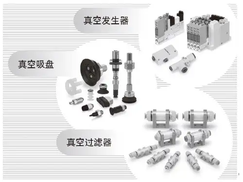
几款真空阀简介及运用电磁真空带充气阀是安装在机械式真空泵上的专用阀门。
阀门与泵接在同一电源上,泵的开启与停止直接控制了阀的开启与关闭。
当泵停止工作或电源突然中断时,阀能自动将真空系统封闭,并将大气通过泵的进气口充入泵腔,避免泵油返流污染真空系统。
适用的工作介质为空气及非腐蚀性气体。
常闭型气动高真空挡板阀是通过电磁转向阀依靠压缩空气作为阀板启闭动力,在失去电源或压缩空气时,通径DN80以下的阀门将依靠弹簧力自动关闭阀门,DN100以上的阀门通过电磁阀组利用单向阀迅速关闭气缸原有的气源压力达到自动关闭阀门。
从而达到真空系统中迅速切断气流之功能。
GDQ-J型为角通型式,GDQ-S型为带预抽口的三通型式。
超高真空插板阀是通过手柄以螺杆传动推动钢球架运动,撑开阀板关闭,又靠弹簧力收拢阀板,打开后再退出的真空阀门。
阀门适用于超高真空系统中接通或截止气流之用。
高真空系统中接通或截止气流之用。
适用的工作介质为洁净的空气和非腐蚀性气体。
低真空电磁压差充气阀是安装在机械真空泵进气口上一种新型真空阀。
其工作原理是机械泵的电源和电磁阀线圈的电源接在同一电路上,当机械真空泵因工作需要突然停电、停止运转时,该阀利用大气压力使阀芯自动关闭,截止和真空系统相连的通道,同时向泵内放大气,防止机械泵油返回真空系统,起到了保护真空系统作用,有利于机械泵再启动。
适用的工作介质为空气及非腐蚀性气体。
电磁高真空充气阀是以电磁力为动力,当接通电源时,阀门被关闭,使真空系统与大气隔离;切断电源时,阀门处于开启状态,随之大气由外界引入真空系统。
GQC-4A型电磁高真空充气阀具有通电开启和通电关闭两种功能,阀内带有空气过滤器,可用作向真空系统充气。
阀门适用的介质为空气及非腐蚀性气体。
电磁高真空挡板阀是靠电磁力和弹簧复位力,用以打开或关闭的阀门,适用于真空系统中用以打开或隔断气流之用。
当阀关闭时,允许阀板密封面上侧承受大气压,下侧为真空,在此状态下接通电器控制盒电源后,阀板能正常开启。
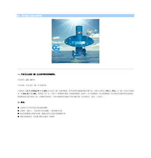
ZZC、ZZV型自力式压力调节阀一、产品[自力式差(微)压力调节阀]的详细资料:产品型号:ZZC、ZZV型产品名称:自力式差(微)压力调节阀产品特点:ZZC和ZZV50mm.WC至0.1MPa自力式差(微)压调节阀是一种不需要外加能源的执行器产品。
可用于公称压力PN0.1、PN10。
差(微)压均可分段调节。
从50mm.WC至0.1MPa。
其用途十分广泛,可用于工业燃烧炉系统,控制两种物料,如煤气、空气流量配比,以达理想燃烧。
用于氢冷发电机组密封油系统,控制密封油与氢气间压力差,以确保可靠密封。
当差压阀的低压端通大气即为微压阀(差压阀负压,端压,力为零)。
二、特点:● 无需停止生产即可进行设定值的调整;● 无填料,阀杆上、下活动时不存在磨擦,上密封绝对可靠● 执行机构敏感元件极为灵敏,极微小的压力变化会被感测出来● 阀体为四通形式,因而K、B型可通用一种阀体三、自力式差(微)压力调节阀主要技术参数和性能指标(表一):额定行程(mm)20 2532 40 50 65 80 100公称压力PN(MPa)差压调节范围(KPa)ZZCP/ZZVP8 11 20 32 50 80 100 160 ZZCN5383额定行程(mm) 6 8 10 15 20公称压力PN(MPa)0.10 1.0差压调节范围(KPa)0.5~5.5 5~10 9~14 13~19 18~24 22~28 26~33 31~38 36~44 42~51 49~58 56~66 64~78 76~90 88~100介质温度(℃)≤80调节精度(%)≤10允许泄漏量(L/H)ZZCP/ZZVP10-4×阀额定容量(IV级)ZZCN5×10-3×阀额定容量(II级)四、自力式差(微)压力调节阀主要技术参数和性能指标(表二)单位:mm:公称通径(DN)2025 3240 5065 80100 A308394308 394 308 394394394H ZZCP/ZZVP376 465 365 445 445 490 490510 ZZCN536536570 590LZZCP/ZZVP150160 180 20 230 290 310350 ZZCN222 222 310350重量(kg)12 13 15 17 20 28 3843导压管螺纹接头M16×1.5五、自力式差(微)压力调节阀主要技术参数和性能指标法兰尽寸(表三):公称通径(DN)20253240506580100D PN01PN10105115140150165185200220D1PN01PN1075 85 100 125145160180b PN01 PN1016182022n-ΦPN01 PN104-144-188-18fl×D2 PN01 PN102×56 3×563×763×843×99 3×118 3×1323×156六、型号编制:订货须知:一、①自力式差(微)压力调节阀产品名称与型号②自力式差(微)压力调节阀口径③自力式差(微)压力调节阀是否带附件二、若已经由设计单位选定公司的自力式差(微)压力调节阀型号,请按自力式差(微)压力调节阀型号三、当使用的场合非常重要或环境比较复杂时,请您尽量提供设计图纸和详细参数,相关产品:气动调节阀ZHYO罐底调节阀ZZYVP氮封阀ZMAS型高压单座角型调节阀Z673H型气动浆液阀气动隔膜衬氟调节阀气动调节球阀ZJHP精小型气动薄膜调节阀调节阀系列价格供用户或设计院工程项目做预算一、阀门的选型步骤1.明确阀门在设备或装置中的用途,确定阀门的工作条件:适用介质、工作压力、工作温度等等。
SMC真空电磁阀介绍1.结构和工作原理:SMC真空电磁阀由电磁操作机构和阀体组成。
操作机构由线圈、活动铁芯和机械机构组成。
当通电时,线圈会产生磁场,吸引活动铁芯与阀体连接。
当通电结束时,磁场消失,活动铁芯会回到原位。
阀体上的气道会根据活动铁芯的位置打开或关闭,从而控制气体进出。
2.特点和优势:(1)高度集成化:SMC真空电磁阀结构紧凑,体积小,安装方便,适用于空间有限的场合。
(2)快速响应:电磁操作机构的动作速度快,开关灵敏,能够在极短的时间内完成开关动作。
(3)耐用可靠:SMC真空电磁阀采用优质材料制造,具有耐腐蚀、耐磨损、抗震动等特性,能够在恶劣的工作环境下长期稳定运行。
(4)低功耗:SMC真空电磁阀采用电磁驱动,仅需瞬时能量就能打开或关闭,能够节约电能。
(5)易于维护:SMC真空电磁阀拥有较长的使用寿命,维护成本低,使用方便。
3.应用领域:由于其独特的优点,SMC真空电磁阀广泛应用于真空系统中,例如:(1)半导体生产设备:用于控制气体进出半导体生产设备的真空室,确保生产过程中的高纯度和稳定性。
(2)分析仪器:用于控制样品的进样、排气和调控系统气压。
(3)实验室设备:用于控制真空室的气压,实现实验过程中的不同气氛要求。
(4)医疗设备:用于控制医疗设备中的真空泵和气体流动,如吸引器和气体分配器等。
(5)机械设备:用于控制真空设备中的气体流动和压力调节。
总结:SMC真空电磁阀是一种高效、可靠、节能的电磁阀产品,具有快速响应、耐用可靠、易于维护等特点。
它在真空系统中的应用非常广泛,为现代工业和科研实验提供了重要的控制手段。
随着科技的不断进步和需求的增加,SMC真空电磁阀将继续发展和应用于更多领域。
真空闸阀规格含义全文共四篇示例,供读者参考第一篇示例:真空阀门是真空系统中不可或缺的重要部件,主要用于控制管路中的气体流动和密封管路,保持管路内的高真空度。
真空阀门有多种类型,其中真空隔膜阀是一种常见的阀门类型,它通过气动控制气压来实现开启和关闭,同时具有良好的密封性能。
为了选择合适的真空阀门,我们需要了解真空阀门规格含义,以便根据实际需求进行正确的选型。
真空阀门的规格通常由一系列字母和数字组成,其中包含了各种参数信息。
下面我们逐个解析这些规格含义:1. 阀门口径:阀门口径是指阀门上的进出口尺寸,通常以英寸(inch)为单位表示。
2英寸口径的真空阀门,表示阀门的进出口尺寸为2英寸,用于连接相应规格的管路。
2. 连接方式:真空阀门的连接方式通常有法兰连接、螺纹连接、焊接连接等。
KF系列阀门采用法兰连接方式,通过KF法兰与真空管路连接,实现快速拆卸和组装。
3. 工作压力:工作压力是指真空阀门可以承受的最大工作压力,通常以帕斯卡(Pa)或者巴(bar)为单位表示。
10^5Pa的真空阀门,表示能承受最高105千帕的工作压力。
4. 密封材料:真空阀门的密封材料对于阀门的密封性能至关重要。
常见的密封材料有橡胶、氟橡胶、聚四氟乙烯等,不同的密封材料适用于不同的工况要求。
5. 控制方式:真空阀门的控制方式包括手动、气动、电动等。
手动控制方式适合小流量、低频率的场合,而气动和电动控制方式适合大流量、高频率的场合。
6. 温度范围:真空阀门需要能够适应不同温度的工作环境,因此其温度范围也是一个重要的参数。
一般来说,真空阀门的温度范围取决于密封材料和阀门的材质。
7. 泄漏率:真空阀门的泄漏率是指在关闭状态下阀门泄漏气体的速率,通常以标准气体体积流量的百分比表示。
泄漏率越低,表示阀门的密封性能越好。
真空阀门规格含义涵盖了阀门口径、连接方式、工作压力、密封材料、控制方式、温度范围和泄漏率等多个参数信息。
了解这些规格含义,有助于我们正确选择符合实际需求的真空阀门,提高系统的工作效率和安全性。
Z/ISE30A 系列压力开关设定说明设定顺序:通电—测量模式—零点校正—功能设定—测量模式产品通电后,自动进入压力测量模式,第一次使用时,请按如下顺序操作。
1、零点校正:产品第一次使用时,通电且不施加气压时,如果显示值不为零,和键同时按住1s 以上,显示值归零。
2、基本功能设定:测量模式下按住键2s 以上,压力开关进入功能设定模式,显示屏显示为。
按和键选择对应功能后按进入详细功能设置。
备注:部分功能为可选功能,根据型号而定。
特定型号下如果不包含某可选功能,对应位置显示。
全部功能列表:项目出厂设置F0:单位选择功能 ISE-Mpa,ZSE-KPa,Option P-psi F1:OUT1规格设定 迟滞模式,常开F2:OUT2规格设定 迟滞模式,常开 F3:响应时间设定 2.5 ms F4:显示精度设定 1/1000 F5:自动预设功能设定 手动模式F6:显示值校正 0% F7:省电模式选择 OFF F8:密码锁设定OFF1)F0-单位选择功能可选功能,部分型号无此功能。
单位不同,显示屏开显示的数值范围不同。
操作方法:按和键选择对应单位,按键确认。
测量模式按住键2s 以上功 能 选 择 模 式功能设定2)F1-OUT1输出规格设定方法:此部分可设置输出类别(迟滞型/比较型)和输出模式(常开/常闭)设定。
按键进入单位选择模式按和键选择对应单位交替显示按键完成设定返回到功能选择模式,屏幕显示F0F0-单位选择功能设定完成输出模式常开型 出厂时默认设置常闭型迟滞模式(出厂时默认设置) 压力输出迟滞(H-1)压力输出压力输出迟滞(H-1)压力输出比较模式(也称窗口比较模式) 迟滞模式(出厂时默认设置) 比较模式(也称窗口比较模式) 迟滞(H1) 迟滞(H1)迟滞(H1) 迟滞(H1)功能选择模式下按和至屏幕显示,然后按进入OUT1规格设定。
压力设定状态:此状态下设定压力开关输出的ON/OFF 点。
以迟滞型为例:输出方法:当压力超过设定值时,开关输出变为ON 。
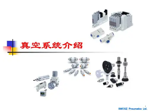
SMC 真空系统SMC 真空系统1·系统概述1·1 系统定义SMC 真空系统是一种专为工业应用而设计和制造的真空设备,旨在实现高效的真空处理和控制。
1·2 系统组成SMC 真空系统由以下几个主要组件组成:1·2·1 真空泵:负责产生和维持所需真空度的装置。
1·2·2 阀门:用于调节真空系统中气体的流动。
1·2·3 传感器:用于监测真空度和其他相关参数。
1·2·4 控制器和仪表:用于控制和监测系统的运转状态。
1·2·5 管道和接头:连接各个组件并确保气体的有效流动。
2·系统安装与调试2·1 设备准备2·1·1 确定系统安装位置和布局。
2·1·2 检查设备和零部件是否完好。
2·1·3 准备所需的安装工具和材料。
2·2 安装步骤2·2·1 安装真空泵和阀门。
2·2·2 连接管道和接头。
2·2·3 安装传感器和控制器。
2·2·4 连接电源线和通信线缆。
2·2·5 进行系统的初步调试。
3·系统操作与维护3·1 系统启动和停止3·1·1 启动系统:按照指示,逐次启动真空泵、控制器和其他组件。
3·1·2 停止系统:按照指示,逐次停止各个组件,确保系统安全关闭。
3·2 真空度控制3·2·1 设置真空度目标值。
3·2·2 调节阀门和真空泵的运行状态以控制真空度。
3·2·3 监测真空度,并及时采取相应措施保持真空度稳定。
3·3 维护与保养3·3·1 定期检查和清洁系统组件。