比例阀控制器说明书-三博中自
- 格式:pdf
- 大小:325.07 KB
- 文档页数:12
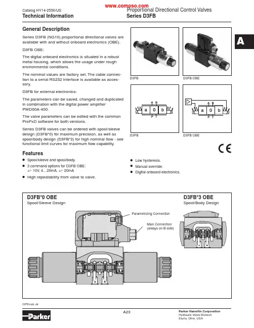
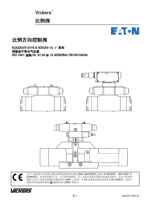
Series D3FBGeneral DescriptionSeries D3FB (NG10) proportional directional valves are available with and without onboard electronics (OBE).D3FB OBE:The digital onboard electronics is situated in a robust metal housing, which allows the usage under rough environmental conditions.The nominal values are factory set. The cable connec-tion to a serial RS232 interface is available as acces-sory.D3FB for external electronics:The parameters can be saved, changed and duplicated in combination with the digital power amplifier PWD00A-400.The valve parameters can be edited with the common ProPxD software for both versions.Series D3FB valves can be ordered with spool/sleeve design (D3FB*0) for maximum precision, as well as spool/body design (D3FB*3) for high nominal flow - see functional limit curves for maximum flow capability.Features• Spool/sleeve and spool/body.• 3 command options for D3FB OBE:+/- 10V , 4…20mA, +/- 20mA• High repeatability from valve to valve.Technical Information D3FB OBED3FB OBED3FBD3FB• Low hysteresis.• Manual override.• Digital onboard electronics.DDirectional Control Size Flow Style Seal SolenoidB WWeight:D3FB 6.5 kg (14.3 lbs.)F0Spool Solenoid Design 3DesignStandardBolt Kit:BK98 (4) 1/4-24x1.625 SHCSBK385 (4) M6x40Design DDirectional ControlSizeFlow StyleSealInput BPlease order plugs separately. See Accessories.Parametrizing cable OBE => RS232 Item no. 40982923FSpool OptionsDesign3Standard* Flow rate for different ∆p per control edge: Qx = QNom.· √ ∆p x∆p Nom.Continued on the next pageSeries D3FBAll performance curves measured with HLP46 at 50°C (122°F).Performance Curves(Electrically set to opening point 10%)Functional Limits100% command signal (symmetric flow). At asymmetric flow a reduced flow limit has to be considered – typically approx. 10% lower.All performance curves measured with HLP46 at 50°C (122°F).Series D3FB (Onboard Electronics)Block Diagrams — WiringCode W511 + PE acc. to EN 175201-804Code F06 + PE acc. to EN 175201-804Code G0, S06 + PE acc. to EN 175201-804Series D3FB (Onboard Electronics) Technical InformationFeatures•Simple editing of all parameters.•Storage and loading of optimized parameter adjustments.•Executable with all Windows® operating systems fromWindows® 95 upwards.•Communication between PC and electronics via serialinterface RS-232.•Simple to use PC user software, free of charge:/euro_hcd– see "Software Downloads"The parametrizing cable may be ordered under item no. 40982923.ProPxD Interface ProgramThe ProPxD software permits comfortable param-eter setting for the module electronics. Via the clearlyarranged entry mask the parameters can be noticedand modified. Storage of complete parameter sets ispossible as well as printout or record as a text file forfurther documentation. Stored parameter sets may beloaded anytime and transmitted to other valves. Insidethe electronics a nonvolatile memory stores the datawith the option for recalling or modification.D3FB*CD3FB*K★Order plugs separately.D3FB*C OBED3FB*E OBE。
![[说明]液压比例阀控制器](https://uimg.taocdn.com/6bbd0f7f001ca300a6c30c22590102020740f2f7.webp)
第六章液压系统比例阀控制器6.1 前言比例控制阀主要用于开回路控制(o pe n loo p co nt rol);比例控制阀的输出量与输入信号成比例关系,且比例控制阀内电磁线圈所产生的磁力大小与电流成正比。
在传统型式的液压控制阀中,只能对液压进行定值控制,例如:压力阀在某个设定压力下作动,流量阀保持通过所设定的流量,方向阀对于液流方向通/断的切换。
因此这些控制阀组成的系统功能都受到一些限制,随着技术的进步,许多液压系统要求流量和压力能连续或按比例地随控制阀输入信号的改变而变化(图6-1.1)。
液压伺服系统虽能满足其要求,而且精度很高,但对于大部分的工业来说,他们并不要求系统有如此高的质量,而希望在保证一定控制性能的条件下,同时价格低廉,工作可靠,维护简单,所以比例控制阀就是在这种背景下发展起来的。
比例控制阀可分为压力控制阀,流量控制及方向控制阀三类(如图6-1.2所示)。
1.压力控制阀:用比例电磁阀取代引导式溢流阀的手调装置便成为引导式比例溢流阀,其输出的液压压力由输入信号连续或按比例控制。
2.流量控制阀:用比例电磁阀取代节流阀或调速阀的手调装置而以输入信号控制节流阀或调速阀之节流口开度,可连续或按比例地控制其输出流量。
故节流口的开度便可由输入信号的电压大小决定。
3.方向控制阀:比例电磁阀取代方向阀的一般电磁阀构成直动式比例方向阀,其滑轴不但可以换位,而且换位的行程可以连续或按比例地变化,因而连通油口间的通油面积也可以连续或按比例地变化,所以比例方向控制阀不但能控制执行组件的运动方向外,还能控制其速度。
以上各种比例阀所作动的液压组件为液压缸或液压马达。
6.2 比例阀控制器内部方块之意义与功能比例阀控制器内部包含各种电路模块,每一个模块有其特定功能及用途并以符号来代表,此处就每一个模块的功能及原理来说明之。
1.斜坡产生器(Ramp Ge ner ator)图6-2.1为斜坡产生器之符号图,斜坡产生器(Ramp Ge ne r ator)主要是将瞬间的电压变化量转换成带有时间延迟的电压变化,也就是说当输入电压改变时,斜坡产生器会将原先的阶梯式电压变化量缓慢地改变到改变后之电压,而在原先电压与改变后电压之间就会得到一随时间上升或下降的斜坡(Ramp),所以Ramp Ge ner ato r斜坡产生的原理跟积分器作用的原理是一样的。
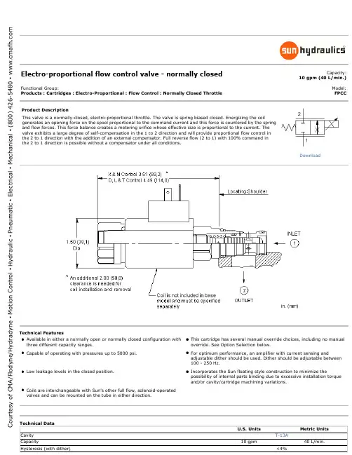
Electro-proportional flow control valve - normally closed Capacity:10 gpm (40 L/min.)Functional Group:Products : Cartridges : Electro-Proportional : Flow Control : Normally Closed Throttle Model: FPCCProduct DescriptionThis valve is a normally-closed, electro-proportional throttle. The valve is spring biased closed. Energizing the coilgenerates an opening force on the spool proportional to the command current and this force is countered by the springand flow forces. This force balance creates a metering orifice whose effective size is proportional to the current. Thevalve exhibits a large degree of self-compensation in the 1 to 2 direction and will provide proportional flow control inthe 2 to 1 direction with the addition of an external compensator. Full reverse flow (2 to 1) with 100% command inthe 2 to 1 direction is possible without a compensator under all conditions.Technical FeaturesThis cartridge has several manual override choices, including no manualoverride. See Option Selection below.For optimum performance, an amplifier with current sensing andadjustable dither should be used. Dither should be adjustable between100 - 250 Hz.Incorporates the Sun floating style construction to minimize thepossibility of internal parts binding due to excessive installation torqueand/or cavity/cartridge machining variations.FPCC-XCN-***C o u r t e s y o f C M A /F l o d y n e /H y d r a d y n e ▪ M o t i o n C o n t r o l ▪ H y d r a u l i c ▪ P n e u m a t i c ▪ E l e c t r i c a l ▪ M e c h a n i c a l ▪ (800) 426-5480 ▪ w w w .c m a f h .c o mControlFlow RateSeal MaterialCoilPreferred OptionsX No Manual OverrideStandard OptionsD Twist/Lock (Dual) ManualOverride L Twist/Lock (Detent) ManualOverride M Manual Override T Twist Manual OverridePreferred OptionsC .25 - 7 gpm (0,8 - 28 L/min.)Standard OptionsA .1 - 1.5 gpm (0,4 - 6 L/min.)B .15 - 3.5 gpm (0,6 - 14 L/min.)D .25 - 10 gpm (1 - 40 L/min.)Preferred Options N Buna-N Standard OptionsVViton*** See Coil Options BelowStandard Coil Options (View All )DIN 43650 3 pin (Hirschman) SAE J858AAMP Junior TimerTwin LeadMetri-PackDeutsch DT04-2P*** no coil 612 AMP Junior Timer 12 VDC 812 Metri-Pack 12 VDC 212 DIN 43650 3 pin(Hirschman) 12 VDC 624AMP Junior Timer 24 VDC824 Metri-Pack 24 VDC 224DIN 43650 3 pin(Hirschman) 24 VDC712 Twin Lead 12 VDC 912 Deutsch DT04-2P 12 VDC 524 SAE J858A 24 VDC724 Twin Lead 24 VDC924Deutsch DT04-2P 24 VDCEmbedded Coil Options (Click Here ) 2B12ADIN 43650 3 pin(Hirschman) command common on fourth pin 12 VDC 0-20 mA2C24VDIN 43650 3 pin(Hirschman) +5V reference on fourth pin 24 VDC 0-10V4A12ADeutsch DT04-6P allfunctions enabled (separate command common, 5 vreference, and an enable) 12 VDC 0-20 mA2B12V DIN 43650 3 pin(Hirschman) command common on fourth pin 12 VDC 0-10V2D12ADIN 43650 3 pin(Hirschman) enable input on fourth pin 12 VDC 0-20 mA4A12VDeutsch DT04-6P allfunctions enabled (separate command common, 5 vreference, and an enable) 12 VDC 0-10V2B24A DIN 43650 3 pin(Hirschman) command common on fourth pin 24 VDC 0-20 mA2D12VDIN 43650 3 pin(Hirschman) enable input on fourth pin 12 VDC 0-10V4A24ADeutsch DT04-6P allfunctions enabled (separate command common, 5 vreference, and an enable) 24 VDC 0-20 mA2B24V DIN 43650 3 pin(Hirschman) command common on fourth pin 24 VDC 0-10V2D24ADIN 43650 3 pin(Hirschman) enable input on fourth pin 24 VDC 0-20 mA4A24VDeutsch DT04-6P allfunctions enabled (separate command common, 5 vreference, and an enable) 24 VDC 0-10V2C12A DIN 43650 3 pin(Hirschman) +5V reference on fourth pin 12 VDC 0-20 mA2D24VDIN 43650 3 pin(Hirschman) enable input on fourth pin 24 VDC 0-10V 4F12VDeutsch DT04-6Pprogrammable ramps, separate rise and fall 12 VDC 0-10V2C12V DIN 43650 3 pin(Hirschman) +5V reference on fourth pin 12 VDC 0-10V 2F12V DIN 43650 3 pin(Hirschman) programmable ramps, separate rise and fall 12 VDC 0-10V4F24VDeutsch DT04-6Pprogrammable ramps, separate rise and fall 24 VDC 0-10V2C24A DIN 43650 3 pin(Hirschman) +5V reference on fourth pin 24 VDC 0-20 mA2F24VDIN 43650 3 pin(Hirschman) programmable ramps, separate rise and fall 24 VDC 0-10VAdditional Options (Click Here )Additional Coils512 SAE J858A 12 VDCC o u r t e s y o f C M A /F l o d y n e /H y d r a d y n e ▪ M o t i o n C o n t r o l ▪ H y d r a u l i c ▪ P n e u m a t i c ▪ E l e c t r i c a l ▪ M e c h a n i c a l ▪ (800) 426-5480 ▪ w w w .c m a f h .c o mStainless options not available for this modelCopyright © 2002-2012 Sun Hydraulics Corporation. All rights reserved.Terms and Conditions - ISO Certification - Statement of PrivacyC o u r t e s y o f C M A /F l o d y n e /H y d r a d y n e ▪ M o t i o n C o n t r o l ▪ H y d r a u l i c ▪ P n e u m a t i c ▪ E l e c t r i c a l ▪ M e c h a n i c a l ▪ (800) 426-5480 ▪ w w w .c m a f h .c o m。
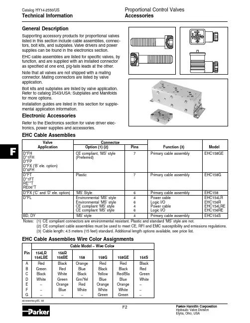
General DescriptionSupporting accessory products for proportional valveslisted in this section include cable assemblies, connec-tors, bolt kits, and subplates. Valve drivers and powersupplies can be found in the electronics section.EHC cable assemblies are listed for specific valves, byfunction, and are supplied with an installed connectoras specified at one end, pig-tails leads at the other.Note that all valves are not shipped with a matingconnector. Mating connectors are listed by valveapplication.Bolt kits and subplates are listed by valve application.Refer to catalog 2543/USA: Subplates and Manifoldsfor more options.Installation guides are listed in this section for supple-mental application information.Electronic AccessoriesRefer to the Electronics section for valve driver elec-tronics, power supplies and accessories.EHC Cable AssembliesValve ConnectorApplication Option (1) (2)Pins Function (3)ModelD*FH CE compliant, ‘MS’ style7Primary cable assembly EHC158GE D*1FH(Preferred)D*FPD*FX (‘B’ ele. option)D*6FHD*FT Plastic7Primary cable assembly EHC158GD*1FTRE**TRE06*TD*FX (‘C’ and ‘D’ ele. option)‘MS’ Style6Primary cable assembly EHC158D*FL Environmental ‘MS’ style4Power cable EHC154LREnvironmental ‘MS’ style6Logic I/O EHC156RCE compliant ‘MS’ style4Power cable EHC154LRECE compliant ‘MS’ style6Logic I/O EHC156RE BD, DY‘MS’ style4Primary cable assembly EHC154SCable Model – Wire ColorPin154LR156R154LRE156RE158158G158GE154SA Red Black Orange Red Red BlackB Green Red Blue Black Black RedC Black White Black Y ellow Red/Bla GreenD White Green Grn/Y el Blue Blue WhiteE–Orange Red Orange Orange–F–Blue White White White–G–––Green Green–EHC Cable Assemblies Wire Color AssignmentsNotes:(1)CE compliant connectors are environmental resistant. Plastic and standard ‘MS’ style are not.(2)CE compliant cable assemblies must be used to meet CE, RFI and EMC susceptibility and emissions regulations.(3)Cable length: 4.5 meters (15 feet) standard. Additional length options available, see price list.Description Variation Order Number DIN 43650Black 692914DIN 43650Grey69291519 (0.75)24 (0.94)∅∅Solenoid ConnectorI/O Connector — D*FLPrimary Connector —D*FT, D*FX (Ele. Design ‘B’), D*FH, D*FM,RE06*T and RE**TDescription Order Number DIN 43563 6+PE5004072Power Connector — D*FLDescription Order Number 4 pin1210292Description Order Number 6 pin D*FL MS3106E-14S-6SRubber Boot 8012276 pin D*FX697561(ele. design A, C & D)LVDT Connector — D*1FSDescriptionOrder Number M12 / 5 pin5004109AccessoriesBolt Kits and SubplatesPort Port Interface Valve Bolt Kit Qty Size Subplate(1)Size Location NG6D1F*BK209410-24 x 1.25"SPD23NS353/8" NPTF Bottom CETOP 3BK3754M5 x 30mm SPD23NAS353/8" NPTF Side RE06BK210410-24 x 1.875"SPD26SS35#12 SAE BottomSPD26SAS35#12 SAE SideNG10D3F*BK9841/4-20 x 1.625"SPD31V6NS353/4" NPTF Bottom CETOP 5BK3854M6 x 40mm SPD31V6NAS353/4" NPTF SideSPD31V6SS35#12 SAE BottomSPD31V6SAS35#12 SAE Side D31F*BK0241/4-20 x 1.5"SPD31V6NS353/4" NPTF BottomBK3854M6 x 40mm SPD31V6NAS353/4" NPTF SideSPD31V6SS35#12 SAE BottomSPD31V6SAS35#12 SAE Side D36F*BK0361/4-20 x 1.5"1402190#16 SAE SideBK4396M6 x 40mmNG16D41F*BK16043/8-16 x 2.5"SPD46SA#12 SAE Side CETOP 721/4-20 x 2.25"BK3204M10 x 60mm2M6 x 55mmD46F*BK15363/8-16 x 2.0"1402191#20 SAE SideBK4406M10 x 50mmNG25D81F*BK22861/2-13 x 3"SPD66NS353/4" NPTF Bottom CETOP 8D91F*BK3606M12 x 75SPD66NAS353/4" NPTF SideSPD68NS351" NPTF BottomSPD68NAS351" NPTF SideSPD610NS35 1 1/4" NPTF BottomSPD610NAS35 1 1/4" NPTF SideSPD610SS35#20 SAE BottomSPD610SAS35#20 SAE Side D96F*BK22761/2-13 x 2.5"1402192#24 SAE SideBK4626M12 x 60mmNG32D111F*BK15063/4-10 x 3.5"SPD1010N35 1 1/4" NPTF Bottom CETOP 10BK3866M20 x 90SPD1012N35 1 1/2" NPTF Bottom (1)Ductile iron; maximum operating pressure: 350 Bar (5075 PSI). Refer to valve specificatons for actual recommendedmaximums.Note:All subplates listed use SAE mounting bolt hardware. Refer to catalog HY14-2543/US for metric options.Valve Installation GuideInstallation GuidesValve Installation Guide Valve Installation GuideBD15/30Cat 1450 ISMBD90/95Bul. IG 1463-000/USABD101Bul. HY14-1484-M1/USEW**104D Bul. 2558-000/USAEZ00595Bul. IG 2561-000/USAD31FS Bul. 2562-M1/USAD41FS Bul. 2562-M2/USAD81FS Bul. 2562-M3/USAD111FS Bul. 2562-M4/USAD1FW Bul. HY14-2563-M1/USD3FW Bul. 2572-M1/USAD**FT Bul. 2580-M1/USAD1FX Bul. 2583-M1/USAD3FX Bul. 2587-M1/USAD41FL andD91FL Bul. 2589-M1/USAD1FL Bul. 2589-M2/USAD3FL Bul. 2589-M3/USAD*FM andD*FH Bul. HY14-2599-M1/USPCD00A Bul. HY11-3236-M1/UKPWDXXA Bul. HY11-5715-602/UKPZD00A Bul. HY11-5715-603/UK。
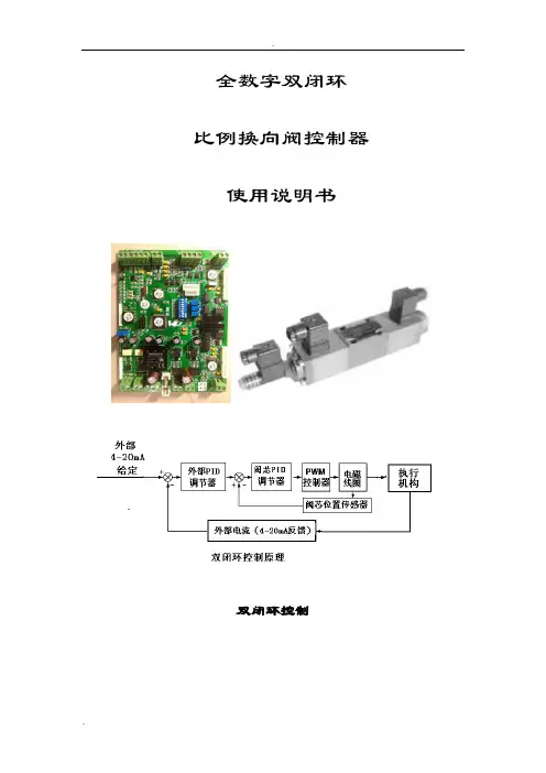
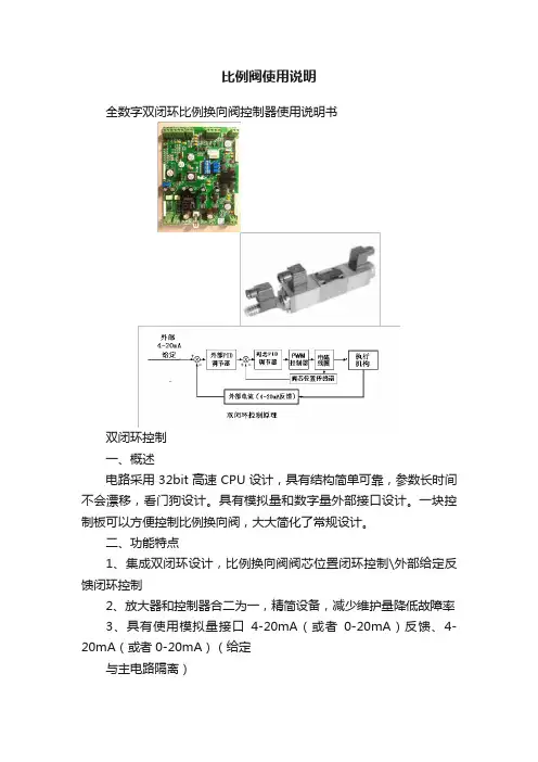
全数字双闭环比例换向阀控制器使用说明书双闭环控制一、概述电路采用32bit高速CPU设计,具有结构简单可靠,参数长时间不会漂移,看门狗设计。
具有模拟量和数字量外部接口设计。
一块控制板可以方便控制比例换向阀,大大简化了常规设计。
二、功能特点1、集成双闭环设计,比例换向阀阀芯位置闭环控制\外部给定反馈闭环控制2、放大器和控制器合二为一,精简设备,减少维护量降低故障率3、具有使用模拟量接口4-20mA(或者0-20mA)反馈、4-20mA(或者0-20mA)(给定与主电路隔离)4、具有数字量接口设计,MODEBUSRS485RTU、CANBUS接口5、可以多个设备进行组网控制,适合多点集中控制6、外部给定反馈闭环控制PID参数调节通过3个电位器调整7、两路阀芯电磁铁控制具有输出过流保护8、看门狗设计,能够及时复位异常工况三、参数1、供电:DC15~30VDC @ 2A2、尺寸123(mm)X160(mm)3、调节精度±1%4、适用范围:华德比例换向阀6通径或10通径带阀芯位置反馈装置进行液压缸、液压缸伸缩位置定位控制,马达行走机构定位控制,液压升降机构定位控制,液压紧紧力装置控制、液压马达行走速度控制等5、工作温度:-30~60摄氏度6、湿度:7、震动:四、典型应用执行机构可以是液压缸,液压马达等执行部件,可以对控制对象进行精准控制五、接线说明六、调整方法此步骤为出厂已经调试好,一般用户无需调整,如果参数确实差异很大,请谨慎操作1、按照接线方法接好线,并认真检查正确后,将控制板上的保险丝去掉,控制板上电后,用万用表的交流档测量COM与L 和COM与R的电压应相同大约在2.3VAC,如果差异大(>0.1VAC)就需要松开位置传感器上的螺丝,将位置传感器的位置通过两个限位螺丝移动,直到测量COM与L 和COM与R的电压应相同为止。
这个步骤一般用户只做检查即可,已经出厂调整过。
如果确实差异很大就必须进行调整。
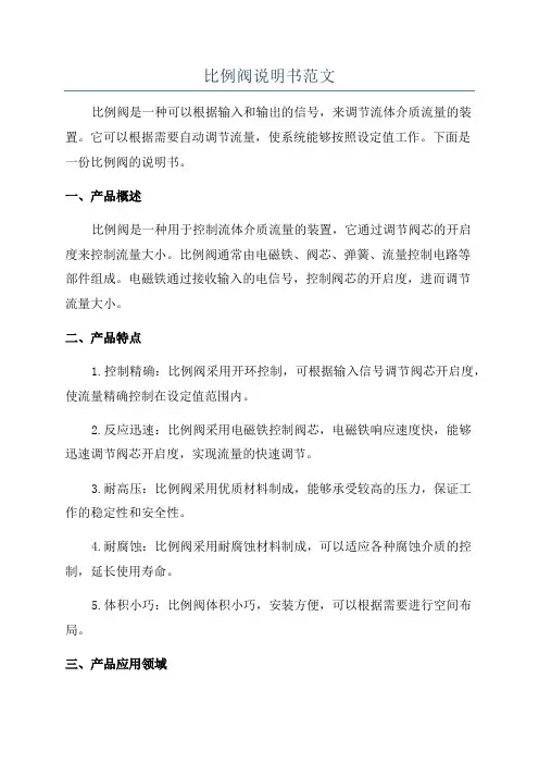
比例阀说明书范文比例阀是一种可以根据输入和输出的信号,来调节流体介质流量的装置。
它可以根据需要自动调节流量,使系统能够按照设定值工作。
下面是一份比例阀的说明书。
一、产品概述比例阀是一种用于控制流体介质流量的装置,它通过调节阀芯的开启度来控制流量大小。
比例阀通常由电磁铁、阀芯、弹簧、流量控制电路等部件组成。
电磁铁通过接收输入的电信号,控制阀芯的开启度,进而调节流量大小。
二、产品特点1.控制精确:比例阀采用开环控制,可根据输入信号调节阀芯开启度,使流量精确控制在设定值范围内。
2.反应迅速:比例阀采用电磁铁控制阀芯,电磁铁响应速度快,能够迅速调节阀芯开启度,实现流量的快速调节。
3.耐高压:比例阀采用优质材料制成,能够承受较高的压力,保证工作的稳定性和安全性。
4.耐腐蚀:比例阀采用耐腐蚀材料制成,可以适应各种腐蚀介质的控制,延长使用寿命。
5.体积小巧:比例阀体积小巧,安装方便,可以根据需要进行空间布局。
三、产品应用领域比例阀可广泛应用于以下领域:1.工业自动化控制系统:比例阀可用于控制各种工业流体介质,如液体、气体等,实现流体流量的准确控制。
2.压力控制系统:比例阀可根据输入的压力信号,控制流体介质的流量,保持系统内的压力稳定。
3.温度控制系统:比例阀可根据输入的温度信号,控制流体介质的流量,实现温度的精确控制。
4.液位控制系统:比例阀可根据输入的液位信号,控制液体介质的流量,实现液位的稳定控制。
四、产品使用方法1.安装:将比例阀安装在需要控制流量的管道上,注意连接的密封性和稳定性。
2.输入信号设置:根据实际需要,将输入信号连接到比例阀的控制电路上。
输入信号可以是电压、电流或者其他类型的信号。
3.设定流量范围:根据实际需要,调节比例阀的开启度,设定所需的流量范围。
4.系统调试:将比例阀接通电源,观察输出流量是否符合设定值,如有偏差可以进一步调节阀芯开启度。
五、产品维护与保养1.定期检查:定期检查比例阀的连接是否松动,电磁铁是否正常工作,阀芯是否磨损,如有异常情况及时进行维修或更换。
比例阀使用说明全数字双闭环比例换向阀控制器使用说明书双闭环控制一、概述电路采用32bit高速CPU设计,具有结构简单可靠,参数长时间不会漂移,看门狗设计。
具有模拟量和数字量外部接口设计。
一块控制板可以方便控制比例换向阀,大大简化了常规设计。
二、功能特点1、集成双闭环设计,比例换向阀阀芯位置闭环控制\外部给定反馈闭环控制2、放大器和控制器合二为一,精简设备,减少维护量降低故障率3、具有使用模拟量接口4-20mA(或者0-20mA)反馈、4-20mA(或者0-20mA)(给定与主电路隔离)4、具有数字量接口设计,MODEBUSRS485RTU、CANBUS接口5、可以多个设备进行组网控制,适合多点集中控制6、外部给定反馈闭环控制PID参数调节通过3个电位器调整7、两路阀芯电磁铁控制具有输出过流保护8、看门狗设计,能够及时复位异常工况三、参数1、供电:DC15~30VDC @ 2A2、尺寸123(mm)X160(mm)3、调节精度±1%4、适用范围:华德比例换向阀6通径或10通径带阀芯位置反馈装置进行液压缸、液压缸伸缩位置定位控制,马达行走机构定位控制,液压升降机构定位控制,液压紧紧力装置控制、液压马达行走速度控制等5、工作温度:-30~60摄氏度6、湿度:7、震动:四、典型应用执行机构可以是液压缸,液压马达等执行部件,可以对控制对象进行精准控制五、接线说明六、调整方法此步骤为出厂已经调试好,一般用户无需调整,如果参数确实差异很大,请谨慎操作1、按照接线方法接好线,并认真检查正确后,将控制板上的保险丝去掉,控制板上电后,用万用表的交流档测量COM与L 和COM与R的电压应相同大约在2.3VAC,如果差异大(>0.1VAC)就需要松开位置传感器上的螺丝,将位置传感器的位置通过两个限位螺丝移动,直到测量COM与L 和COM与R的电压应相同为止。
这个步骤一般用户只做检查即可,已经出厂调整过。
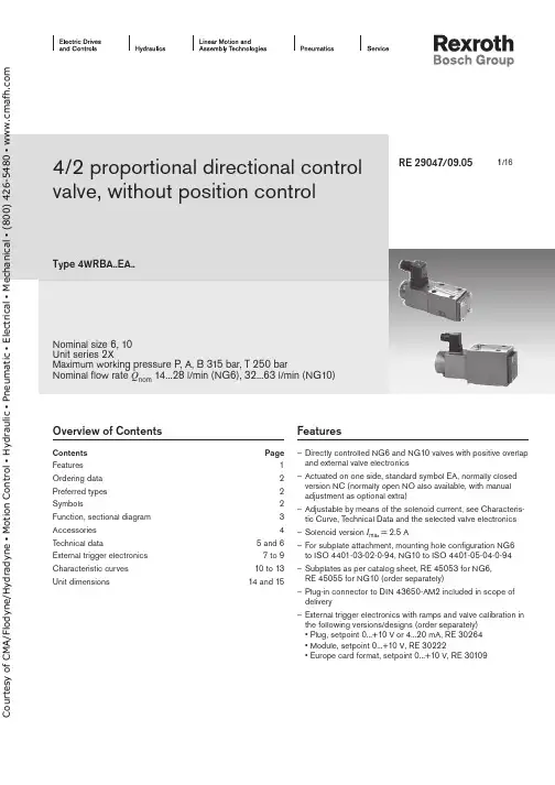
1/164/2 proportional directional control valve, without position controlType 4WRBA..EA..Nominal size 6, 10Unit series 2XMaximum working pressure P, A, B 315 bar, T 250 barNominal flow rate Q nom 14...28 l/min (NG6), 32...63 l/min (NG10)RE 29047/09.05Overview of ContentsContents PageFeatures 1Ordering data 2Preferred types2Symbols 2Function, sectional diagram 3Accessories 4T echnical data5 and 6External trigger electronics 7 to 9Characteristic curves 10 to 13Unit dimensions14 and 15Features– D irectly controlled NG6 and NG10 valves with positive overlap and external valve electronics– Actuated on one side, standard symbol EA, normally closed version NC (normally open NO also available, with manual adjustment as optional extra)– Adjustable by means of the solenoid current, see Characteris-tic Curve, T echnical Data and the selected valve electronics – Solenoid version I max = 2.5 A– For subplate attachment, mounting hole configuration NG6 to ISO 4401-03-02-0-94, NG10 to ISO 4401-05-04-0-94– Subplates as per catalog sheet, RE 45053 for NG6, RE 45055 for NG10 (order separately)– Plug-in connector to DIN 43650-AM2 included in scope of delivery– External trigger electronics with ramps and valve calibration in the following versions/designs (order separately)• Plug, setpoint 0...+10 V or 4...20 mA, RE 30264• Module, setpoint 0...+10 V, RE 30222• Europe card format, setpoint 0...+10 V, RE 30109o u r t e s y o f C M A /F l o d y n e /H y d r a d y n e ▪ M o t i o n C o n t r o l ▪ H y d r a u l i c ▪ P n e u m a t i c ▪ E l e c t r i c a l ▪ M e c h a n i c a l ▪ (800) 426-5480 ▪ w w w .c m a f h .c o mOrdering dataPreferred typesNG6 Solenoid 2.5 A NG10 Solenoid 2.5 A TypeMaterial Number TypeMaterial Number 4WRBA6EA15–2X/G24N9Z4/M 0 811 403 1054WRBA10EA32–2X/G24N9Z4/M 0 811 403 0204WRBA6EA30–2X/G24N9Z4/M 0 811 403 1044WRBA10EA64–2X/G24N9Z4/M0 811 403 0214WRBA6XA30–2X/G24N9Z4/M–8920 811 403 1084WRBA6XA30–2X/G24NZ4/M–8930 811 403 109SymbolsActuation: A-side..E.. ..= X..1) ..= X..2)o u r t e s y o f C M A /F l o d y n e /H y d r a d y n e ▪ M o t i o n C o n t r o l ▪ H y d r a u l i c ▪ P n e u m a t i c ▪ E l e c t r i c a l ▪ M e c h a n i c a l ▪ (800) 426-5480 ▪ w w w .c m a f h .c o mFunction, sectional diagramGeneralType 4WRBA 4/2 proportional directional control valves without position control are also known as “throttle valves”. These d irectly controlled valves are available in nominal sizes 6 and 10.Hysteresis is < 4 % for the NG6 and < 5 % for the NG10. The valve amplifier electronics are available in various designs for 2.5 A solenoids. The operating limits are largely determined by the available magnetic force, see characteristic curves for single or double flow.Basic principleT o adjust the oil flow rate, a setpoint is set in the triggerelectronics. Based on this setpoint, the electronics control the solenoid coil with regulated PWM (pulse-width-modulated)c urrent.The current is modulated with a dither, ensuring low hysteresis. The proportional solenoid converts the current to a mechanical force, with which an armature plunger acts on a spool to push against the spring. If the magnetic force and the spring force are the same, this produces a spool position in conformity with the spring characteristic curve. If the drop in pressure is minimal (< 30 bar) the throttling function takes effect, if the pressure drop is greater, the operating limits (see characteristic curves) must be observed.The pressure drop at the valve is reliably limited by the use of an external pressure compensator or regulating pump.Control solenoidValve bodyManual adjustment 4WRBA..EA..N..Manual auxiliary overrideNG6NG10Manual auxiliary overrideValve bodyControl solenoido u r t e s y o f C M A /F l o d y n e /H y d r a d y n e ▪ M o t i o n C o n t r o l ▪ H y d r a u l i c ▪ P n e u m a t i c ▪ E l e c t r i c a l ▪ M e c h a n i c a l ▪ (800) 426-5480 ▪ w w w .c m a f h .c o mTesting and service equipmentT est box type VT-PE-TB1, see RE 30063T est adapter type VT-PA-3, see RE 30070Current measuring adapter type VT-PA-5, see RE 30073AccessoriesTypeMaterial Number (4x) f ISO 4762-M5x30-10.9Cheese-head bolts NG6 2 910 151 166(4x) f ISO 4762-M6x35-10.9Cheese-head bolts NG102 910 151 207PlugVT-SSPA1-525-20/V0 (2.5 A)RE 302640 811 405 143VT-SSPA1-525-20/V0/I (2.5 A)0 811 405 145Module VT-MSPA1-525-10/V0 (2.5 A)RE 302220 811 405 127Europe card VT-VSPA1-525-10/V0/RTP (2.5 A)RE 301090 811 405 079Plug-in connector2P+PEPlug-in connector 2P+PE (M16x 1.5)included in scope of delivery, see also RE 08008o u r t e s y o f C M A /F l o d y n e /H y d r a d y n e ▪ M o t i o n C o n t r o l ▪ H y d r a u l i c ▪ P n e u m a t i c ▪ E l e c t r i c a l ▪ M e c h a n i c a l ▪ (800) 426-5480 ▪ w w w .c m a f h .c o mTechnical data1432Port P, A, B: 315Port T: 2501) T he purity classes stated for the components must becomplied with in hydraulic systems. Effective filtrationprevents problems and also extends the service life of components.For a selection of filters, see catalog sheets RE 50070, RE 50076 and RE 50081.* N ominal flowThis is always based on a pressure differential of ∆p = 5 bar at the throttling point.Where other pressure differentials are involved, the flow is calculated according to the following formula: ∆p XQ x = Q nom ·Ί 5However, the operating limits must be borne in mind.If they are exceeded, the ensuing flow forces lead touncontrollable spool movements. Pressure compensators are used to reliably limit ∆p .o u r t e s y o f C M A /F l o d y n e /H y d r a d y n e ▪ M o t i o n C o n t r o l ▪ H y d r a u l i c ▪ P n e u m a t i c ▪ E l e c t r i c a l ▪ M e c h a n i c a l ▪ (800) 426-5480 ▪ w w w .c m a f h .c o mTechnical dataElectricalCyclic duration factor %100Degree of protection IP 65 to DIN 40050 and IEC 14434/5Solenoid connection Unit plug DIN 43650/ISO 4400, M16x 1.5 (2P+PE)Valve with solenoid type NG6NG10Max. solenoid current I max A 2.5 2.5Coil resistance R 20⍀3 5.8Max. power consumption at 100 % VA load and operating temperature3055Static/Dynamic 1)ysteresis %Յ 4Յ 5Range of inversion %Յ 3Յ 3Manufacturing tolerance%ഠ10ഠ10Response time 100 % signal changems On Ͻ 70Off Ͻ 701001) A ll characteristic values ascertained using amplifier 0 811 405 079 for the 2.5 A solenoid.o u r t e s y o f C M A /F l o d y n e /H y d r a d y n e ▪ M o t i o n C o n t r o l ▪ H y d r a u l i c ▪ P n e u m a t i c ▪ E l e c t r i c a l ▪ M e c h a n i c a l ▪ (800) 426-5480 ▪ w w w .c m a f h .c o mValve with external trigger electronics (plug, RE 30264)Circuit diagram/pin assignment1) Version with 0...+10 V signal 2) Version with 4...20 mA signalConnection/adjustment P1 – Ramp timeP2 – Sensitivity P3 – ZeroP4 – Dither frequency St1 – T erminal LED – U B displayo u r t e s y o f C M A /F l o d y n e /H y d r a d y n e ▪ M o t i o n C o n t r o l ▪ H y d r a u l i c ▪ P n e u m a t i c ▪ E l e c t r i c a l ▪ M e c h a n i c a l ▪ (800) 426-5480 ▪ w w w .c m a f h .c o mValve with external trigger electronics (module, RE 30222)Circuit diagram/pin assignmentFront view/adjustmento u r t e s y o f C M A /F l o d y n e /H y d r a d y n e ▪ M o t i o n C o n t r o l ▪ H y d r a u l i c ▪ P n e u m a t i c ▪ E l e c t r i c a l ▪ M e c h a n i c a l ▪ (800) 426-5480 ▪ w w w .c m a f h .c o mValve with external trigger electronics (europe card, RE 30109)Circuit diagram/pin assignmento u r t e s y o f C M A /F l o d y n e /H y d r a d y n e ▪ M o t i o n C o n t r o l ▪ H y d r a u l i c ▪ P n e u m a t i c ▪ E l e c t r i c a l ▪ M e c h a n i c a l ▪ (800) 426-5480 ▪ w w w .c m a f h .c o mCharacteristic curves NG6 (measured with HLP 46,oil = 40 °C ±5 °C)Valve amplifier1) Zero adjustment 2) Sensitivity adjustment 3) Version: U E= 0...+10 V4)Version: I E= 4...20 mAU E 3)[V]I E 4)[mA]44,47,510,613,816,920Q nom = 28 l/minQ nom= 14, 28 l/minI E 4)[mA]U E 3)[V]44,47,510,613,816,920o u r t e s y o f C M A /F l o d y n e /H y d r a d y n e ▪ M o t i o n C o n t r o l ▪ H y d r a u l i c ▪ P n e u m a t i c ▪ E l e c t r i c a l ▪ M e c h a n i c a l ▪ (800) 426-5480 ▪ w w w .c m a f h .c o mCharacteristic curves NG6 (measured with HLP 46,oil = 40 °C ±5 °C)Operating limitso u r t e s y o f C M A /F l o d y n e /H y d r a d y n e ▪ M o t i o n C o n t r o l ▪ H y d r a u l i c ▪ P n e u m a t i c ▪ E l e c t r i c a l ▪ M e c h a n i c a l ▪ (800) 426-5480 ▪ w w w .c m a f h .c o mCharacteristic curves NG10 (measured with HLP 46,oil = 40 °C ±5 °C)Q nom = 32, 63 l/minValve amplifier1) Zero adjustment 2) Sensitivity adjustment 3) Version: U E= 0...+10 V4) Version: I E= 4...20 mA47,54,410,613,816,920U E )[V]I E4)[mA]o u r t e s y o f C M A /F l o d y n e /H y d r a d y n e ▪ M o t i o n C o n t r o l ▪ H y d r a u l i c ▪ P n e u m a t i c ▪ E l e c t r i c a l ▪ M e c h a n i c a l ▪ (800) 426-5480 ▪ w w w .c m a f h .c o mCharacteristic curves NG10 (measured with HLP 46,oil = 40 °C ±5 °C)Operating limitso u r t e s y o f C M A /F l o d y n e /H y d r a d y n e ▪ M o t i o n C o n t r o l ▪ H y d r a u l i c ▪ P n e u m a t i c ▪ E l e c t r i c a l ▪ M e c h a n i c a l ▪ (800) 426-5480 ▪ w w w .c m a f h .c o mRequired surface quality of mating componentMounting hole configuration: NG6 (ISO 4401-03-02-0-94)For subplates see catalog sheet RE 450531) Deviates from standard 2) T hread depth:Ferrous metal 1.5 x ØNon-ferrous 2 x ØManual adjustmentX Yo u r t e s y o f C M A /F l o d y n e /H y d r a d y n e ▪ M o t i o n C o n t r o l ▪ H y d r a u l i c ▪ P n e u m a t i c ▪ E l e c t r i c a l ▪ M e c h a n i c a l ▪ (800) 426-5480 ▪ w w w .c m a f h .cMounting hole configuration: NG10 (ISO 4401-05-04-0-94)For subplates see catalog sheet RE 450551) Deviates from standard 2) Thread depth:Ferrous metal 1.5 x Ø* Non-ferrous 2 x Ø* NG10 min. 10.5 mmRequired surface quality of mating componentX Yo u r t e s y o f C M A /F l o d y n e /H y d r a d y n e ▪ M o t i o n C o n t r o l ▪ H y d r a u l i c ▪ P n e u m a t i c ▪ E l e c t r i c a l ▪ M e c h a n i c a l ▪ (800) 426-5480 ▪ w w w .c m a f h .cBosch Rexroth AG HydraulicsZum Eisengießer 197816 Lohr am Main, Germany T elefon +49 (0) 93 52 / 18-0T elefax +49 (0) 93 52 / 18-23 58*****************************www.boschrexroth.de© This document, as well as the data, specifications and other information set forth in it, are the exclusive property of Bosch Rexroth AG. It may not be reproduced or given to third parties without its consent.The data specified above only serve to describe the product. No state-ments concerning a certain condition or suitability for a certain application can be derived from our information. The information given does not release the user from the obligation of own judgement and verification. It must be remembered that our products are subject to a natural process of wear and aging.o u r t e s y o f C M A /F l o d y n e /H y d r a d y n e ▪ M o t i o n C o n t r o l ▪ H y d r a u l i c ▪ P n e u m a t i c ▪ E l e c t r i c a l ▪ M e c h a n i c a l ▪ (800) 426-5480 ▪ w w w .c m a f h .c。
General DescriptionSeries D**FL proportional directional control valves arepackaged with an integrated microprocessor basedopen-loop motion profiler. The valve directly acceptselectrical on/off logic signals which trigger simple mo-tion profiles controlling actuator speed, acceleration,and deceleration.D**FL valves are user configurable to operate in oneof two control modes: ‘Slow Shift’ or ‘Motion Profiler’.Refer to application guidelines for details. Both DC andAC voltage logic interfaces are available providing a di-rect interface to PLC’s, for a simple field upgrade fromAC operated directional valves.Valves are available in sizes NG6 (CETOP 3), NG10(CETOP 5), NG16 (CETOP 7) and NG25 (CETOP 8).Features•Integrated microprocessor based valve electronics.•On-board, open-loop motion control profiler.•Optically isolated ‘on-off’ inputs trigger motion profiles.•User selectable operation modes: Slow Shift or Profiler.•T est points indicating speed and ramp settings.•On-board microprocessor self diagnostics on start-up.Technical Information Series D**FLSpecificationsInterface DIN NG6 NG10 NG16 NG25(CETOP 3) (CETOP 5) (CETOP 7) (CETOP 8) Flow Rating @10 Bar (150 PSI) ∆p (P→A, B→T)(spool options up to)1)LPM (GPM) 20 (5.3) 60 (15.9) 100 (26) 200 (53) Maximum Flow LPM 27 34.1 30 62.1 83.3 118 144372(GPM) (7.3) (9) (8) (18) (22) (31) (38) (98) Pilot FlowContinuous LPM (GPM) N/A N/A <1.2 (0.3) <1.2 (0.3) Step Input LPM (GPM) N/A N/A 2.2 (0.6) 4.5 (1.2) Operating PressurePort P, A, B Bar (PSI) 315 (4500) 345 (5000) max.Port P, internal pilot N/A 20 (290) min.Port T, internal drain 35 (500) 10 (150) max.Port T, external drain N/A 345 (5000) max.Port Y, pilot drain N/A 10 (150) max.Port X, external pilot N/A 20-345 (290-5000)Fluid Cleanliness Level ISO Class 16/13Fluid Viscosity, Recommended 80 – 1000 SSUFluid Temperature, Recommended 0°C to +60°C (+32°F to +140°F) Environmental Protection Class NEMA 4 (IP65)Ambient Operating Temperature -20°C to +60°C (-4°F to +140°F)1) Actual pressure drop required for each metering land, up to the specified maximum flow rate is:Q actualQ rated[or] = (75) ()2PSI; (Q in GPM)Q actualQ rated∆P actual = (5) ()2Bar; (Q in LPM)•LED functional diagnostic indicators.•Spring centered spool.•Manual overrides.Flow rate for different ∆p per control edge: Qx= QNom.· √∆p x∆p Nom.Series D**FL Ordering InformationWeight: D41FL 10.9 kg (24.0 lbs.) D91FL19.1 kg (42.0 lbs.)Code Pilot Drain1 Internal External2 External External 4 Internal Internal 5External InternalCode DescriptionT AC Voltage Logic Interface W DC VoltageLogic InterfaceMounting InterfaceRefer to Mounting Interface Dimensions inthe Proportional Directional Valve section of this catalog.AccessoriesRefer to the Accessories section for bolt kits, subplates, connectors and pre-assembled cable assemblies.Code Description 0 Standard2 Pilot Pressure Reducer (3)4 CSA Approved (3) Recommended for pilot pressure applications>205 Bar (3000 PSI)Flow at ∆p 5 Bar (72.5 PSI) per metering edge CodeD41FL D91FLLPM (GPM) LPM (GPM)D100 (26.5)–F–200 (53)Code Description N NitrileV FluorocarbonDesign Series NOTE: Not required when ordering.D*FLProportional Directional Spool TypeFlowStyleElectronic Accessories SealElectronic Supply Voltage Valve AccessoriesCJ 0Design Series NOTE: Not required when ordering.D**FLPilot Operated Proportional Spool TypeFlowStyleElectronic Accessories Pilot ConnectionSealElectronic VariationValve AccessoriesC* Only with spool type E*1) Reduced flow rate on Port B, nominal flow on Port A.Code Description TAC Voltage Logic Interface W DC VoltageLogic InterfaceCode Description J24 VDCWeight:D1FL 3.2 kg (7.0 lbs.) D3FL7.9 kg (17.5 lbs.)Note 1: NG10 (CETOP5) valves are supplied with bolt kitBK98 (1/4-20 x 1.625). For metric bolt kit BK385 (M6 x 40 mm), add “-X6181” to ordering code.Code Description 0 Standard 4 CSA ApprovedElectrical SpecificationsSeries D**FLApplication GuidelinesSupply Voltage V 12 to 28Maximum CurrentA 3.5Motion Profile Adjustment User set; potentiometers inside electronics enclosure.Speed0 to 100% valve opening; two speeds forward, two speeds retract. Ramps (minimum limited by actual 0.025 to 15 seconds; one acceleration, two deceleration adjustments. valve step response) Shared both forward/retract.Test PointsInside electronics enclosure.V1, V2, V3, V4 0 to 5 volts, corresponding to 0 to 100% valve opening, or speed. R1, R2, R30 to 5 volts, corresponding to 0.025 to 15 seconds ramp time.Logic InterfaceOrdering code field: Electrical variation W T (options available all valve sizes)Electrical Isolation DC Optical-Coupled AC Optical-Coupled Polarity Signal pins A, C & E; referenced to Signal pins A, C & E; referenced to 0V pins B, D & F respectively. AC neutral pins B, D & F respectively.Input Impedance ohms >2000 >2000Input Voltage , Absolute Max. V 28 VDC 130 VAC Logic “on” (1), Min. Voltage V >9.6 VDC >96 VAC Logic “on” (1), Current mA 3.2 mA 3.2 mA Logic “off” (0), Min. Voltage V <6.0 VDC <51 VAC Logic “off” (0), Current mA 3.2 mA 3.2 mA Mating Connectors (order separately) Power Supply Connector Part # 1210292 (4-pin MS)Logic Input ConnectorPart # MS3106E-14S-6S (6-pin MS)The D**FL series proportional valves accept discrete on/off logic signals which trigger simple motion profiles controlling actuator speed, acceleration, and decel-eration. All motion control potentiometer adjustments and jumper headers are located inside the electronics enclosure. Two modes of operation are user select-able by a jumper setting (JP1): ‘Motion Profiler’ or ‘Slow Shift’. The ‘Motion Profiling’ mode provides two-speed velocity control typically used in rapid traverse and feed circuits. The ‘Slow Shift’ provides single velocity control. Both modes allow individual speed adjustment for actuator extend and retract. Ramp adjustments for extend and retract profiles are shared.Refer to Interface and Motion Profile diagrams on the following pages.Both DC and AC voltage logic interfaces are available. Refer to ordering code field ‘Electronic Variation’ and the technical data sheet for more information. Note that the interface connections are polarity sensitive. Refer to the block diagram and technical specifications.Refer to the Installation Guide for set-up, configuration, and application guidelines (packaged with each valve):D1FL: Installation Guide Bulletin 2589-M2/USA D3FL:Installation Guide Bulletin 2589-M3/USAD41FL,D91FL: Installation Guide Bulletin 2589-M1/USAInterface — ‘Motion Profiler’ mode (see timing diagram below)The ‘Motion Profiler’ mode is selected by removing connecting jumper ‘JP1’ on the electronics card inside the electronics enclosure. To trigger a rapid traverse, opening the valve P →A / B →T; apply a positive logic signal to logic inputs ‘Select Profile A’, and ‘Select High Speed’ (6-pin connector input pins A&B, and C&D). The valve will smoothly accelerate the actuator to the velocity set by potentiometer ‘V1’, at a ramp rate set by potentiometer ‘R1’. When logic input ‘Select High Speed’ is deselected the actuator will smoothly decelerate the actuator to the feed velocity set by Potentiometer ‘V2’, at a ramp rate set by potentiometer ‘R2’. When logic input ‘Select ProfileA’ is deselected the actuator will smoothly decelerate the actuator to a stop at a ramp rate set by potentiometer ‘R3’. When neither ‘Select Profile’ inputs are selected, regardless of the ‘Select High Speed’ input state, the valve is held in the centered hydraulic condition. Reversing the actuator, directing flow P →B / A →T, follows the same logic using logic input ‘Select Profile B’. Refer to the timing diagram below for the corresponding potentiometers. Note that although all four speeds are independent, the three ramps are shared by both ‘A’ and ‘B’ profiles.Block Diagram — WiringNotes:1) DC logic source shown, refer to technical data for A.C.2) 0V reference for DC interface, neutral for AC version.R1V1R2V2R3R1V3R2V4R3Flow P A®Flow P B®Select Profile ‘A’Select High Speed Select Profile ‘B’111000Interface — ‘Slow Shift’ mode (see timing diagram below)The ‘Slow Shift’ mode is selected by connecting jumper ‘JP1’ on the electronics card inside the electronics en-closure. The ‘Slow Shift’ mode logically operates the same as the ‘Motion Profiler’ mode, except the ‘Select High Speed’ logic input is not used and only one speed for each actuator direction is available.4-Pin Power Supply Plug6-Pin Logic Input PlugD AC BPin DescriptionA Supply VoltageB Protective GroundC Supply 0VD Not UsedPin DescriptionA Select Profile “A” (+)B Select Profile “A” (0V or neutral)C Select “High Speed” (+)D Select “High Speed” (0V or neutral)E Select Profile “B” (+)F Select Profile “B” (0V or neutral)DEFACBFlow P B®R1R1V1R2R2tV3Flow P A®Select Profile‘A’Select High Speed(not used)Select Profile‘B’111D3FLInch equivalents for millimeter dimensions are shown in (**)313.5(12.38)195.0(7.68)70.0(2.76)46.0(1.81)BAD91FLInch equivalents for millimeter dimensions are shown in (**)46.0(1.81)268.8(10.59)92.0(3.62)44.5(1.75)151.6(5.97)164.0(6.46)228.0(8.98)102.8(4.05)BPA46.0(1.81)287.7(11.33)58.0(2.29)116.0(4.57)76.0(2.99)306.0(12.06)178.6(7.04)230.0(9.06)102.8(4.05)BPA。
全数字双闭环比例换向阀控制器使用说明书双闭环控制一、概述电路采用32bit高速CPU设计,具有结构简单可靠,参数长时间不会漂移,看门狗设计。
具有模拟量和数字量外部接口设计。
一块控制板可以方便控制比例换向阀,大大简化了常规设计。
二、功能特点1、集成双闭环设计,比例换向阀阀芯位置闭环控制\外部给定反馈闭环控制2、放大器和控制器合二为一,精简设备,减少维护量降低故障率3、具有使用模拟量接口4-20mA(或者0-20mA)反馈、4-20mA(或者0-20mA)(给定与主电路隔离)4、具有数字量接口设计,MODEBUSRS485RTU、CANBUS接口5、可以多个设备进行组网控制,适合多点集中控制6、外部给定反馈闭环控制PID参数调节通过3个电位器调整7、两路阀芯电磁铁控制具有输出过流保护8、看门狗设计,能够及时复位异常工况三、参数1、供电:DC15~30VDC @ 2A2、尺寸123(mm)X160(mm)3、调节精度±1%4、适用范围:华德比例换向阀6通径或10通径带阀芯位置反馈装置进行液压缸、液压缸伸缩位置定位控制,马达行走机构定位控制,液压升降机构定位控制,液压紧紧力装置控制、液压马达行走速度控制等5、工作温度:-30~60摄氏度6、湿度:7、震动:四、典型应用执行机构可以是液压缸,液压马达等执行部件,可以对控制对象进行精准控制五、接线说明六、调整方法此步骤为出厂已经调试好,一般用户无需调整,如果参数确实差异很大,请谨慎操作1、按照接线方法接好线,并认真检查正确后,将控制板上的保险丝去掉,控制板上电后,用万用表的交流档测量COM与L 和COM与R的电压应相同大约在2.3VAC,如果差异大(>0.1VAC)就需要松开位置传感器上的螺丝,将位置传感器的位置通过两个限位螺丝移动,直到测量COM与L 和COM与R的电压应相同为止。
这个步骤一般用户只做检查即可,已经出厂调整过。
如果确实差异很大就必须进行调整。
第六章液壓系統比例閥控制器6.1 前言比例控制閥主要用於開迴路控制(open loop control);比例控制閥的輸出量與輸入信號成比例關係,且比例控制閥內電磁線圈所產生的磁力大小與電流成正比。
在傳統型式的液壓控制閥中,只能對液壓進行定值控制,例如:壓力閥在某個設定壓力下作動,流量閥保持通過所設定的流量,方向閥對於液流方向通/斷的切換。
因此這些控制閥組成的系統功能都受到一些限制,隨著技術的進步,許多液壓系統要求流量和壓力能連續或按比例地隨控制閥輸入信號的改變而變化(圖6-1.1)。
液壓伺服系統雖能滿足其要求,而且精度很高,但對於大部分的工業來說,他們並不要求系統有如此高的品質,而希望在保證一定控制性能的條件下,同時價格低廉,工作可靠,維護簡單,所以比例控制閥就是在這種背景下發展起來的。
比例控制閥可分為壓力控制閥,流量控制及方向控制閥三類(如圖6-1.2所示)。
1.壓力控制閥:用比例電磁閥取代引導式溢流閥的手調裝置便成為引導式比例溢流閥,其輸出的液壓壓力由輸入信號連續或按比例控制。
2.流量控制閥:用比例電磁閥取代節流閥或調速閥的手調裝置而以輸入信號控制節流閥或調速閥之節流口開度,可連續或按比例地控制其輸出流量。
故節流口的開度便可由輸入信號的電壓大小決定。
3.方向控制閥:比例電磁閥取代方向閥的一般電磁閥構成直動式比例方向閥,其滑軸不但可以換位,而且換位的行程可以連續或按比例地變化,因而連通油口間的通油面積也可以連續或按比例地變化,所以比例方向控制閥不但能控制執行元件的運動方向外,還能控制其速度。
237以上各種比例閥所作動的液壓元件為液壓缸或液壓馬達。
6.2 比例閥控制器內部方塊之意義與功能比例閥控制器內部包含各種電路模組,每一個模組有其特定功能及用途並以符號來代表,此處就每一個模組的功能及原理來說明之。
1.斜坡產生器(Ramp Generator)圖6-2.1為斜坡產生器之符號圖,斜坡產生器(Ramp Generator)主要是將瞬間的電壓變化量轉換成帶有時間延遲的電壓變化,也就是說當輸入電壓改變時,斜坡產生器會將原先的階梯式電壓變化量緩慢地改變到改變後之電壓,而在原先電壓與改變後電壓之間就會得到一隨時間上升或下降的斜坡(Ramp),所以Ramp Generator斜坡產生的原理跟積分器作用的原理是一樣的。