MULTISIM 标准方波产生电路图
- 格式:doc
- 大小:52.50 KB
- 文档页数:1
课程设计(论文)说明书题目:方波、三角波、正弦波发生器院(系):专业:学生姓名:学号:指导教师:职称:2012年12 月 5 日摘要本文通过介绍一种电路的连接,实现函数发生器的基本功能。
将其接入电源,并通过在显示器上观察波形及数据,得到结果。
电压比较器实现方波的输出,又连接积分器得到三角波,并通过差分放大器电路得到正弦波,得到想要的信号。
NI Multisim 软件结合了直观的捕捉和功能强大的仿真,能过快速、轻松、高效地对电路进行设计和验证。
凭借NI Multisim ,你可以立即创建具有完整组件库的电路图,并利用0工业标准SPICE模拟器模仿电路行为。
本设计就是利用Multisim软件进行电路图的绘制并进行仿真。
关键词:电源、波形、比较器、积分器、MultisimAbstractThis paper introduces a circuit connection, to achieve the basic functions of function generator. Their access to power, and through the display of waveform and data, and get the result.A voltage comparator to achieve a square wave output, in turn connected integrator triangle wave, and through the triangle wave - sine wave conversion circuit to see the sine wave, the desired signal.NI Multisim software combines intuitive capture and powerful simulation, an quickly, easily, efficiently for circuit design and verification. With NI Multisim, you can immediately create a complete component library circuitdiagram, and the use of 0 industry standard SPICE simulator to mimic circuit behavior. This design is the use of Multisim software in circuit diagram and carry out simulationKey words: power, waveform, comparator, an integrator, a converter circuit, Multisim目录1 设计任务---------------------------------------11.1 电路设计任务------------------------------11.2 电路设计要求------------------------------12正弦波、方波发生器的组成------------------------12.1 原理框图----------------------------------12.2 原理分析----------------------------------12.3 放大器功能及管脚图------------------------23 系统中各模块设计--------------------------------23.1方波-三角波-正弦波-------------------------23.1.1方波形仿真图-----------------------------43.1.2三角波仿真电路图以及仿真图---------------43.1.3正弦波仿真图-----------------------------63.1.4实验设计电路图---------------------------63.1.5实验电路PCB图---------------------------73.1.6参数设计---------------------------------73.2元器件型号---------------------------------94 电路调试---------------------------------------104.1 安装正弦波、方波发生器- ------------------134.2调试正弦波、方波发生器---------------------134.3调试结果展示------------------------------134.3.1方波实验波形图--------------------------114.3.2三角波实验波形图------------------------114.3.3正弦波实验波形图------------------------124.3.4实际电路图及实物图展示------------------124.4性能指标测量与误差分析--------------------135 实验总结--------------------------------------13谢辞、参考文献-----------------------------------14一设计任务1.1 任务设计制作一个方波-三角波-正弦波发生器。
课程设计(论文)说明书题目:方波、三角波、正弦波发生器院(系):专业:学生:学号:指导教师:职称:2012年12 月 5 日....摘要本文通过介绍一种电路的连接,实现函数发生器的基本功能。
将其接入电源,并通过在显示器上观察波形及数据,得到结果。
电压比较器实现方波的输出,又连接积分器得到三角波,并通过差分放大器电路得到正弦波,得到想要的信号。
NI Multisim 软件结合了直观的捕捉和功能强大的仿真,能过快速、轻松、高效地对电路进行设计和验证。
凭借NI Multisim ,你可以立即创建具有完整组件库的电路图,并利用0工业标准SPICE模拟器模仿电路行为。
本设计就是利用Multisim软件进行电路图的绘制并进行仿真。
关键词:电源、波形、比较器、积分器、MultisimAbstractThis paper introduces a circuit connection, to achieve the basic functions of function generator. Their access to power, and through the display of waveform and data, and get the result.A voltage comparator to achieve a square wave output, in turn connected integrator triangle wave, and through the triangle wave - sine wave conversion circuit to see the sine wave, the desired signal.NI Multisim software combines intuitive capture and powerful simulation, an quickly, easily, efficiently for circuit design and verification. With NI Multisim, you can immediately create a complete component library circuitdiagram, and the use of 0 industry standard SPICE simulator to mimic circuit behavior. This design is the use of Multisim software in circuit diagram and carry out simulationKey words: power, waveform, comparator, an integrator, a converter circuit, Multisim..目录1 设计任务---------------------------------------11.1 电路设计任务------------------------------11.2 电路设计要求------------------------------12正弦波、方波发生器的组成------------------------12.1 原理框图----------------------------------12.2 原理分析----------------------------------12.3 放大器功能及管脚图------------------------23 系统中各模块设计--------------------------------23.1方波-三角波-正弦波-------------------------23.1.1方波形仿真图-----------------------------43.1.2三角波仿真电路图以及仿真图---------------43.1.3正弦波仿真图-----------------------------63.1.4实验设计电路图---------------------------63.1.5实验电路PCB图---------------------------73.1.6参数设计---------------------------------73.2元器件型号---------------------------------94 电路调试---------------------------------------104.1 安装正弦波、方波发生器- ------------------134.2调试正弦波、方波发生器---------------------134.3调试结果展示------------------------------134.3.1方波实验波形图--------------------------114.3.2三角波实验波形图------------------------114.3.3正弦波实验波形图------------------------124.3.4实际电路图及实物图展示------------------124.4性能指标测量与误差分析--------------------13..5 实验总结--------------------------------------13辞、参考文献-----------------------------------14....一 设计任务1.1 任务设计制作一个方波-三角波-正弦波发生器。
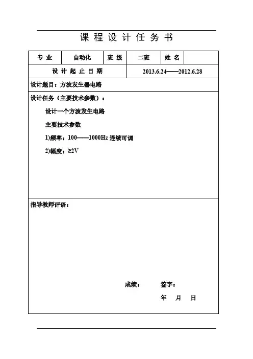
课程设计任务书专业自动化班级二班姓名设计起止日期2013.6.24——2012.6.28设计题目:方波发生器电路设计任务(主要技术参数):设计一个方波发生电路主要技术参数1)频率:100——1000Hz连续可调2)幅度:≥2V指导教师评语:成绩:签字:年月日图(1)方波发生电路原理框图沈阳大学课程设计说明书N O.3图(2)方波发生电路图2.3 工作原理设某一时刻输出电压uO=+UZ,则同相输入端电位沈阳大学课程设计说明书N O.4通过正反馈,使输出很快变为高电平或低电平。
图(4) 输出电压Uo波形而方波发生电路中电容正向充电与反向充电的时间常数均为RC,而且充电的总课程设计说明书N O.5图(5)仿真原理图沈阳大学图(6)仿真波形由图可知方波的幅度>2V,波形无明显失真满足课设的幅值条件。
沈阳沈 阳 大 学图(7) 频率调节仿真图由公式:)21ln(2213R R C R T +=则振荡频率:由于频率的范围是100Hz≤f≤1000Hz当f=100Hz 时,代入公式的R≈3kΩ,KeyA=100%,对比频率仿真结果知f=122.792Hz,接近100Hz 。
当f=1000Hz 时,代入公式的 R≈300Ω,KeyA=5%,对比频率仿真结果知f=815.68Hz,接近1000Hz 。
由仿真结果知方波形连续可调频率范围基本符合在100Hz 至1000Hz 之间满足课设的要求。
3.误差分析:理论参数与Multisim 11仿真分析及应用电路测试结果略有不同,主要是由于电路中二极管的动态电阻以及稳压二极管的正向导通电压引起的误差,所以使频率达不到1000HZ 。
)21ln(21132R R RC Tf +==。
课程设计(论文)说明书题目:方波、三角波、正弦波发生器院(系):专业:学生姓名:学号:指导教师:职称:2012年12 月 5 日摘要本文通过介绍一种电路的连接,实现函数发生器的基本功能。
将其接入电源,并通过在显示器上观察波形及数据,得到结果。
电压比较器实现方波的输出,又连接积分器得到三角波,并通过差分放大器电路得到正弦波,得到想要的信号。
NI Multisim 软件结合了直观的捕捉和功能强大的仿真,能过快速、轻松、高效地对电路进行设计和验证。
凭借NI Multisim ,你可以立即创建具有完整组件库的电路图,并利用0工业标准SPICE模拟器模仿电路行为。
本设计就是利用Multisim软件进行电路图的绘制并进行仿真。
关键词:电源、波形、比较器、积分器、MultisimAbstractThis paper introduces a circuit connection, to achieve the basic functions of function generator. Their access to power, and through the display of waveform and data, and get the result.A voltage comparator to achieve a square wave output, in turn connected integrator triangle wave, and through the triangle wave - sine wave conversion circuit to see the sine wave, the desired signal.NI Multisim software combines intuitive capture and powerful simulation, an quickly, easily, efficiently for circuit design and verification. With NI Multisim, you can immediately create a complete component library circuitdiagram, and the use of 0 industry standard SPICE simulator to mimic circuit behavior. This design is the use of Multisim software in circuit diagram and carry out simulationKey words: power, waveform, comparator, an integrator, a converter circuit, Multisim目录1 设计任务---------------------------------------11.1 电路设计任务------------------------------11.2 电路设计要求------------------------------12正弦波、方波发生器的组成------------------------12.1 原理框图----------------------------------12.2 原理分析----------------------------------12.3 放大器功能及管脚图------------------------23 系统中各模块设计--------------------------------23.1方波-三角波-正弦波-------------------------23.1.1方波形仿真图-----------------------------43.1.2三角波仿真电路图以及仿真图---------------43.1.3正弦波仿真图-----------------------------63.1.4实验设计电路图---------------------------63.1.5实验电路PCB图---------------------------73.1.6参数设计---------------------------------73.2元器件型号---------------------------------94 电路调试---------------------------------------104.1 安装正弦波、方波发生器- ------------------134.2调试正弦波、方波发生器---------------------134.3调试结果展示------------------------------134.3.1方波实验波形图--------------------------114.3.2三角波实验波形图------------------------114.3.3正弦波实验波形图------------------------124.3.4实际电路图及实物图展示------------------124.4性能指标测量与误差分析--------------------135 实验总结--------------------------------------13谢辞、参考文献-----------------------------------14一设计任务1.1 任务设计制作一个方波-三角波-正弦波发生器。
课程: Multisim课程设计班级: 10电信本2班姓名: 6 2 2 学号: 100917024教师:吕老师课程设计----基于Multisim的方波、三角波和正弦波发生器一.设计目的1.掌握电子系统的一般设计方法2.掌握模拟IC器件的应用3.培养综合应用所学知识来指导实践的能力4.掌握常用元器件的识别和测试5.熟悉常用仪表,了解电路调试的基本方法二.设计要求能够同时显示出方波、三角波和正弦波。
三.设计原理函数发生器一般是指能自动产生正弦波、三角波、方波及锯齿波、阶梯波等电压波形的电路或仪器。
根据用途不同,有产生三种或多种波形的函数发生器,使用的器件可以是分立器件 (如低频信号函数发生器S101全部采用晶体管),也可以采用集成电路(如单片函数发生器模块8038)。
为进一步掌握电路的基本理论及实验调试技术,本课题采用由集成运算放大器与晶体管差分放大器共同组成的方波—三角波—正弦波函数发生器的设计方法。
产生正弦波、方波、三角波的方案有多种,如首先产生正弦波,然后通过整形电路将正弦波变换成方波,再由积分电路将方波变成三角波;也可以首先产生三角波—方波,再将三角波变成正弦波或将方波变成正弦波等等。
本课题采用先产生方波—三角波,再将三角波变换成正弦波的电路设计方法,本课程设计中函数发生器电路组成框图如下所示:由比较器和积分器组成方波—三角波产生电路,比较器输出的方波经积分器得到三角波,三角波到正弦波的变换电路主要由差分放大器来完成。
差分放大器具有工作点稳定,输入阻抗高,抗干扰能力较强等优点。
特别是作为直流放大器时,可以有效地抑制零点漂移,因此可将频率很低的三角波变换成正弦波。
波形变换的原理是利用差分放大器传输特性曲线的非线性。
图1 原理框图方波发生电路工作原理此电路由反相输入的滞回比较器和RC电路组成。
RC回路即作为迟滞环节,又作为反馈网络,通过RC冲、放电实现输出状态的自动转换。
设某一时刻输出电压Uo=+Uz,则同相输入端电位Up=+Ut,Uo通过R3对电容C正向充电,如图中箭头所示。
课程设计(论文)说明书题目:方波、三角波、正弦波发生器院(系):专业:学生姓名:学号:指导教师:职称:2012年12 月 5 日摘要本文通过介绍一种电路的连接,实现函数发生器的基本功能。
将其接入电源,并通过在显示器上观察波形及数据,得到结果。
电压比较器实现方波的输出,又连接积分器得到三角波,并通过差分放大器电路得到正弦波,得到想要的信号。
NI Multisim 软件结合了直观的捕捉和功能强大的仿真,能过快速、轻松、高效地对电路进行设计和验证。
凭借NI Multisim ,你可以立即创建具有完整组件库的电路图,并利用0工业标准SPICE模拟器模仿电路行为。
本设计就是利用Multisim软件进行电路图的绘制并进行仿真。
关键词:电源、波形、比较器、积分器、MultisimAbstractThis paper introduces a circuit connection, to achieve the basic functions of function generator. Their access to power, and through the display of waveform and data, and get the result.A voltage comparator to achieve a square wave output, in turn connected integrator triangle wave, and through the triangle wave - sine wave conversion circuit to see the sine wave, the desired signal.NI Multisim software combines intuitive capture and powerful simulation, an quickly, easily, efficiently for circuit design and verification. With NI Multisim, you can immediately create a complete component library circuitdiagram, and the use of 0 industry standard SPICE simulator to mimic circuit behavior. This design is the use of Multisim software in circuit diagram and carry out simulationKey words: power, waveform, comparator, an integrator, a converter circuit, Multisim目录1 设计任务---------------------------------------11.1 电路设计任务------------------------------11.2 电路设计要求------------------------------12正弦波、方波发生器的组成------------------------12.1 原理框图----------------------------------12.2 原理分析----------------------------------12.3 放大器功能及管脚图------------------------23 系统中各模块设计--------------------------------23.1方波-三角波-正弦波-------------------------23.1.1方波形仿真图-----------------------------43.1.2三角波仿真电路图以及仿真图---------------43.1.3正弦波仿真图-----------------------------63.1.4实验设计电路图---------------------------63.1.5实验电路PCB图---------------------------73.1.6参数设计---------------------------------73.2元器件型号---------------------------------94 电路调试---------------------------------------104.1 安装正弦波、方波发生器- ------------------134.2调试正弦波、方波发生器---------------------134.3调试结果展示------------------------------134.3.1方波实验波形图--------------------------114.3.2三角波实验波形图------------------------114.3.3正弦波实验波形图------------------------124.3.4实际电路图及实物图展示------------------124.4性能指标测量与误差分析--------------------135 实验总结--------------------------------------13谢辞、参考文献-----------------------------------14一设计任务1.1 任务设计制作一个方波-三角波-正弦波发生器。