GEQ系列安装维护手册(中文)
- 格式:pdf
- 大小:533.62 KB
- 文档页数:20
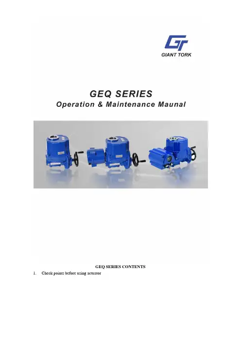
1.Check points before using actuator1)Mechanical2)Electrical3)Others2.Introduction of GEQ series actuator1)Name of main part2)Specification3)Features4)Mounting Base(ISO5211)5)Removable drive busing3.Application4.Setting1)Manual operation2)Limit switches3)Torque switches4)Stopper bolts5)Indicator5.Location of actuator on the pipeline1)Location of actuator on the pipeline2)Orientation of actuator6.Electrical Wiring1)Cable and entries2)Electrical wiring3)Checking the rotating direction of actuator4)Commissioning(Electrical)7.Others1)Change the rotating direction of actuator(open to close, close to open)2)Setting of potentiometer3)Solve problem of Jamming4)Special tools of setting8.Precaution before using actuator9.After sales service1)Free of charge2)User is charge3)Trouble shootings10.Maintenance1)Lubrication2)Regular operation for examination3)Regular maintenance4)Othersz Thanks for purchasing our GEQ series actuatorBefore installing or operating actuator, please carefully read this manual to know thoroughly how toinstall or operate.The contents in this manual are subject to change due to the quality improvement without individual notice.1.Check points before using actuator1)MechanicalCheck external: check if drive bushing, painting, handle and lever are O.K or not.Compare specification: compare if specification of the delivered actuator is suitable for your specification of application.Check options: check if all options are correct or not.2)ElectricalCheck if electrical specification is correct or not (wiring diagram inside of actuator, name plate).Check if the electrical power is correct or not.3)Other checking pointsCheck if instruction manual, test report (warranty papers) and electrical wiring diagram are supplied or not.2.Introduction of GEQ Actuator1)Name of main parts2) PerformanceRated current(A)50-60Hz 1 phase 3 phase Type (model)Max output Torque (Nm)Operating time 60/50Hz (Sec)90° Max bore size(mm) 110V220V380V440VNum of handle turn Weig ht(Kg)GEQ-008 80 13/16 ¢20 1.10/0.950.55/0.54N/A N/A 10 7.4 GEQ-010 100 17/20 ¢20 1.10/0.950.55/0.54N/A N/A 10 7.4 GEQ-015 150 21/25 ¢22 1.65/1.670.88/0.840.31/0.310.30/0.31 11 16.6GEQ-020 200 21/25 ¢22 1.67/1.670.89/0.850.31/0.310.30/0.31 11 16.6GEQ-030 300 26/31 ¢35 1.85/1.860.92/0.920.35/0.350.34/0.34 13.5 22 GEQ-050 500 26/31 ¢35 3.60/3.62 1.55/1.580.59/0.590.58/0.58 13.5 23 GEQ-060 600 26/31 ¢35 3.65/3.62 1.60/1.620.60/0.590.59/0.58 13.5 23 GEQ-080 800 31/37 ¢45 4.10/4.10 2.15/2.200.85/0.850.79/0.79 16.5 29 GEQ-120 1200 31/37 ¢45 4.20/4.10 2.35/2.300.87/0.870.81/0.81 16.5 29 GEQ-200 2000 93/112 ¢65 4.10/4.10 2.15/2.300.85/0.850.79/0.79 49.5 75 GEQ-300300093/112¢654.20/4.102.15/2.300.87/0.870.81/0.8149.575Standard specification Enclosure Weatherproof IP67, NEMA 4 and 6Power supply 110/220V AC 1PH, 380/440/460V AC,3 Phase,50/60Hz,±10% Control power supply 110/220V AC 1PH, 50/60Hz, ±10% Duty cycle(on-off duty) S2,20~50% Max 10Min~30Min Motor Squirrel caged induction motor Limit switches2×open/close,SPDT,250V AC 10A ratingAdditional limit switches 2×open/close,SPDT,250V AC 10A rating(except GEQ-008) Torque switchesOpen/close,SPDT,250V AC 10A rating(except GEQ-008) Stall protection/operating temp Built-in thermal protection, open 150℃±5℃/close 97℃±15℃ Travel angle 90°±10°(0°~10°) Indicator Continuous position indicatorManual override Declutching mechanismSelf locking Provided by means of worm gearing Mechanical stopper 2×external adjustable screwsSpace heater 10W (110/220V AC )Anti-condensation Conduit entries Three PF3/4” TapLubrication Grease molly (EP type )MaterialsSteel, Subminimum alloy, Al bronze, Polycarbonate Ambient temperature -20℃~+70℃(except option electronic board ) Ambient humidity 90% RH Max.(non-condensing) Anti vibration X Y Z 10g,0.2 34Hz, 30 minuteExternal costingDry power, Polyester Mussel no. 5R 3.5/12Option specificationEXA Explosion proof enclosure actuator(Eexd Ⅱ B T4)WTA Watertight enclosure actuator(IP68 10M 72HR)unit(1K-10K)PIU PotentiometerPCU Proportional control unit(input,output 0~10V DC,4~20mA DC)ATS Additional torque switches(SPDT 2EA 250V AC 10A Rating)unit(LCU+IMS+ phase protect indicator)controlSICU Semi-integralICU Intelligent Digital control unit(LCU+IMS+auto phase discriminator)positiontransmitter(output 4~20mA DC)CPT Current120°,180°,270° turnEXT ExtensionCycle: 70% max(in Ambient temp)HDM DutyDCM DCmotor(24V DC)controlADCM AC/DC24VLPA Lever plate actuatorSLU Signal lamp unit(white-power on,red-open,green-close,yellow-over torque)Actuator1050±5℃/50 minProofingFPA1 Fire250±5℃/150 minActuatorProofingFPA2 Fire3)Features and structure(1)GeneralGEQ series actuator is designed for the 90 degree turn application such as damper, ball, plug, butterfly valve and other equipment.(2)Range of torqueMin. 80Nm to Max 3000Nm. In between there are 9 models and cater for various torque depending on application.Models are GEQ-008,015,020,030,050,060,080,120,200 and 300.Applicable size of valveButterfly valve: 50mm (2”) ~600mm (24”)Ball valve: 40mm (1 1/2”) ~350mm (16”)(3)BodyMaterial is hard-anodized AL alloy and external coating of epoxy powder is suitable for thesevere condition especially against the corrosion.Housing is designed in accordance with standard of ex-proof and IP68.(4)SealingSealing carried out by the O-rings guaranties IP68 (10m under water 10days)(5)Manual OverrideJust by pulling over the lever, operating mode is switched to manual.And just supplying electrical power to actuator, clutch is automatically disengaged from manual and operating mode is switched to electric operation.(6)Gear & Self locking2nd staged double worm gearing prevents movement caused by back force transferred from valve and it provides the exact and stable position of actuator and valve when electrical power is off.High efficiency, low noise level and trouble free design are another advantage.(7)Manual hand wheelThe size of hand wheel is designed according to required torque to move the actuator, so that operator can easily move the actuator by hand.(8)MotorMotor specially designed for GEQ actuator has several features such as high output power, high efficiency and thermostat installed inside of motor prevent overheat of and thermal damage of motor coil.(9)Limit switchSince limit switch is directly driven by the 2nd output shaft, position during operation is continuous and accurate.Setting of cam is so easy and once cam setting is done, position is almost permanent unless operators change setting again.(10)Torque switchTorque switch driven by the 2nd output drive shaft for continuous and accurate torque detection. Torque spring which detects the variation of torque during operation is installed for preventing damage of valve and actuator under overload condition. Once actuator is under overload, torque switch is tripped and actuator stops immediately.Switches are installed for both open and close direction. This switches set by factory can not be set again without check with factory.(11)Space heaterSpace heater is installed for preventing damage caused by condensed water inside of actuator and includes thermostat inside to prevent overheating. Temperature of heater can be set as per environment condition.(12)Stopper boltStopper bolt installed both close and open direction prevents actuator’s travel over the limit during manual operation and also protects internal gearing from its breakaway.(13)IndicatorIndicator directly driven by 2nd output drive shaft has 4 signal LED’s to show the current operating situation of actuator (open/close/over torque/power on-off). Operator perceives exact current operating situation even from a distance.(14)Terminal blockSpring loaded terminal strip is very strong against vibration and to add the number of strip for additional connection is so simple.(15)WiringBasic wiring is standardized to be simplest and optimal, so that variation depending on electrical specification and options can be so easy and simple.(16)AdaptionMounting base is designed according to ISO5211 but different dimension depending on application is also possible. Removable drive bushing provides convenient machining for adaption.(17)LubricationUsing Grease Molly EP type, no need to refill lubricant for the long time.(18)OthersGEQ guaranty high performance, high quality product throughout various and severe test and inspection.4)Mounting baseMounting base (ISO5211)5)Actuator drive bushing1)Above table just show reference and no guaranty!2)Sizing should be done after careful reviewing valve factory, temperature, characteristics offluid and etc.3)Having application under special condition such as high and low temperature, seawater,severe corrosion, high vibration), please consult with our technical dept before selecting actuator.4)Decision by user ignoring our recommendation, we have right to avoid any responsibility. 4.Setting1)Manual operation(1)Pull over the lever toward hand wheel until lever stands perpendicularly.(2)If lever does not stand perpendicularly, pull over it again turning hand wheel slowly.(3)There is casting mark to indicate rotating direction on hand wheel.(4)Clockwise is close direction and counter clockwise is open direction.(5)No need to position the lever to original for electrical operation.(6)Once electrical power is on, the lever automatically return its original position by internalclutch mechanism.2)Limit switch setting(1)Pull over the lever for manual operation and turn hand wheel to move actuator full close (oropen) position.(2)Loose the bolts tightening cam by L-wrench, and turn CLS (or OLS) cam to CW (or toCCW), so that cam may hit the lever of close (or open) limit switch. Then tighten the boltby L-wrench.3)Torque switchesTorque switches are set by factory before delivery and therefore no need to set the switches again, but just do as follows for check if switches functions well.(1)Push the lever of close switches by screw driver until it sounds “click” then actuator shouldstop immediately. If it stops, switches work well.(2)Check open switches as per just same with above.(3)No guaranty in performance once these switches are set again.(4)Before setting, if it is compulsory, please consult with factory.4)Stopper bolt setting(1)Before manual operation, get both nuts loose which are engaged with stopper bolts and turnstopper bolt to come out by 3~4 threads.(2)Move actuator full close position by manual. Once cam hit lever of limit switch to trip, stopmanual operation.(3)Then turn close stopper bolt to go forward until it do not go further (end of stopper boltcontacts the 2nd worm wheel).(4)Turn close stopper bolt to come out by 2 threads and tighten the loosen nut.(5)Do as per same with above for open stopper bolt.5)Indicator setting1)Move actuator full close position and turn indicator by hand until orientation of indicator isaligned to the figure of window.2)Tighten the bolt (be careful not to be injured by the cutting edge of indicator and leakage ofelectricity when power is on).3)Figure of window and indicator4)Signal LED’sWHITE LED ON: POWER ONGREEN LED ON: OPENRED LED ON: CLOSEYELLOW LED ON: OVER TORQUE SWIT CHES TRIP (EXCEPT GEQ-008)5.Recommendation for installation of actuator in the pipeline1)Location of actuator on the pipelineMIN. MIN. MIN. MIN. MIN.2)Orientation of installation of actuator * No limit, but it is recommended to install actuator inthe position which cable entry face the ground orientation for watertight function and handwheel faces front for easy manual operation without interruption, * Reserve the space for maintenance.6.Electrical wiring1)Cable and conduit cable entries are machined and sealed by plug before factory.(1)Please remain the plug as it is if user doesn’t use both cable entries.(2)Please make sure to seal the entries by using rubber or metallic packing after wiring, so thatwater may not come in.(3)When user use actuator as ex-proof, please make sure to use the certified connectioncomponent which is at least same grade with actuator. This is not our scope of supply, but ifuser don’t use suitable component, factory won’t guaranty the performance of ex-proof actuator.2)Electrical wiring(1)Check if electrical specification like as power, wiring & etc are correct or not.(2)One sheet of wiring diagram is to be supplied together with actuator.(3)Do the wiring as per the given wiring diagram, such as power, control power, internalwiring and ground.(4)Make sure to supply electric power to heater for keeping inside of actuator clean and dry.(5)Make sure to check wiring to the terminal is strong enough.(6)Make sure that one relay operates one actuator only. Can not operate two or more actuatorssimultaneously.(7)Make sure to clean inside of actuator and no foreign material inside.3)Check rotating direction(1)In 3 phase actuator, operator should check the rotating direction of actuator before electricaloperation.(2)If operating direction is wrong, limit switches doesn’t function and it results damage fromjamming or motor’s overheating. So put the actuator at 50% open (or close) position by manual and supply power into the actuator and check its rotating direction.(3)If actuator moves to open as per open signal, the direction it is O.K, but reverse, need tochange the wiring. Among 3 of power wires, change 2 wires each other. Then check the rotating direction again in order to confirm it again.4)Commissioning(1)Make sure to check the rotating direction of actuator first before operation.(2)Check the function of limit and torque switches, direction of indicator, signal LED’s andspace heater.(3)Check lever movement is O.K ( Manual override)(4)Check the lamps in the control panel.(5)After commission, please make sure to tighten the 4 bolts of the top cover and to do propersealing.7.Others1)Reverse direction actuatorGenerally actuator is set as close clockwise and opens counterclockwise. If user wants to use reverse direction actuator, please do as follows.GEQ -015~GEQ-300 (on –off)(1)Open the cover using L-wrench(2)Change wires each other which are connected to terminal No 6 and 7 and do the same wayfor 8 and 9.(3)Change the direction of indicator (for GEQ-200 and 300, change window also)(4)Put actuators about 50% open position and check rotating direction is correct.GEQ -015~GEQ-300 (Proportional control)(1)Open the cover using L-wrench(2)Change wires each other which are connected to terminal No P1 and P3 in the PCU card(3)Change wires each other which are connected to terminal No 9 and 10 and do same way for11 and 12.(4)Change the direction of indicator ( for GEQ-200 and 300, change the window also)(5)Put actuators about 50% opens position and just push the auto setting button.(6)Supply 4~20mA and check the operation.2)Potentiometer setting(1)Put actuator full close position and check resistance between P1 (orange) and P3(Grey), itshould be around 1000Ohm.(2)Engage potentiometer gear with pointer shaft gear and tighten the bolt.(3)Put spring between potentiometer and pointer shaft and fix both.(4)If user wants to use reverse direction actuator, change the wires of P1(orange) and P3 (Grey)of PIU each other.3)JammingIn case that actuator moves wrong direction and moves over the travel limit, internal worm gear contacts the stopper bolt and engaged each other. This is we call, jamming and can not move actuator at all.How to solve(1)Off the power(2)If jamming is happened during close, take close stopper bolt to come out by about 2~3threads.(3)Pull over the lever and put it manual position.(4)Turn hand wheel to counterclockwise until 50% open position.(5)Check rotating direction again.(6)If everything is O.K, put stopper bolt original position.(7)If jamming is happened during open, procedure is same with close, but turn hand wheel toclockwise by manual.4)Special tools for setting(1)L-wrench 1 set ( Metric)(2)Screw drives (-,+)(3)Spanner set (Metric), Monkey spanner 200mm, 300 1 each(4)Wire stripper, long nose, Light(5)Multi Meter (AC, DC V olt, Resistance)(6)DC signal generator (0~4mA DC): PCU option(7)MA DC Meter (0~25mA DC): PCU and CPT8.CautionSelection of valve and actuator: Review all specification of valve and actuator carefully before making selection and reserve about 30% torque of actuator for safety purpose. If required torque is 90Nm, recommended actuator torque is about 117Nm.1)Option: please consult with factory before making selection, if possible.2)Before necessary setting such as limit switch, please don’t operate actuator either fully openor fully close.3)After electrical wiring, make sure to secure the sealing of cable entries.4)Before operating actuator, please review this manual carefully and follow the instructionwithout fail. Please be careful at temperature, humidity, vibration, voltage drop.5)Storage: keep actuator dry, clean and cool.6)Trouble: please refer to following trouble shooting but please don’t dismantle the actuatorwithout consulting with factory.7)If repair or maintenance is required, please check the model, electrical condition, serialNumber and current situation to inform factory.9.After sales service1)Free of charge(1)When delivered actuator is different from the specification of customer’s order.(2)When quality of actuator is different from the specification published by GEQ.(3)When trouble of component is found.(4)When trouble is generally recognized as factory’s fault. Warranty period is 1 year afterdeliver.2)Charge(1)When trouble caused by misuse ignoring actuator specification.(2)When trouble caused by user’s mistake or intention (Dismantling)(3)When trouble caused by modification by user’s intention.(4)When trouble caused by not checking of rotating direction for 3 phase actuator.(5)When trouble caused by the un-proper sealing of cable entries.(6)When trouble caused by fire, flood and other natural disaster.(7)When trouble is generally recognized as user’s fault.(8)When trouble happen after warranty period.3)Trouble shooting(1)110/220V AC 1 PH, 380/440V AC 3PH standard actuatorTrouble Cause Counter plan Check if power is on Power on Check if voltage is too low Check powerMotor and supplied power is different Check motor power and supplied powerWiring is not correct and tight or loosenDo wiring again tightly Coil of motor is damaged Change the motor Thermostat of motor trips Change thermostat Capacitor is damagedChange the capacitor Setting of limit and torque switch is not correctDo setting switches again Actuator doesn’t work atallJamming happensCheck rotating direction per instructionActuator is undersizedSelect again as per real require Foreign material between valve seat and disc Remove foreign material Torque switchopenStopper bolt is set prior to limit switchReset the stopper bolt Lever is not fully pulled overFully pull over the lever Lever is not pulled over because of jamming Disengage the jamming Switching to manual is not possible Clutch of lever and handle is engaged each otherTurning handle slowly, pull over leverDamage of signal LED Change the signal LED Damage of micro switches Change the micro switches Setting limit switch is wrong Do setting switch again Abnormal signal indicatorStopper bolt is set prior to limit switchDo setting stopper bolt again10. Maintenance1) LubricationLubrication is already done by factory and generally no need to refill it again.But in the places such as very dry condition below R.H 15% or high temperature higher than 30o C, it is required to do lubrication once two year through Grease Nipple. 2) Regular operationElectrical power always should be supplied to actuator and it is recommended to operate actuator once a week. 3) MaintenanceIn order to use actuator for long time that regular maintenance once a year is required. Pleas check operating condition, corrosion, painting & etc. 4) OthersShould you have any further queries, please contact us through Phone, fax and E-mail without hesitation.。
G E L O G I Q B O O K X P中文操作手册(总57页)--本页仅作为文档封面,使用时请直接删除即可----内页可以根据需求调整合适字体及大小--开机操作按Power On/Off开关(如下图),系统上电。
指示灯说明:1. 硬盘指示灯。
绿色闪烁代表硬盘正在工作。
2. 提示系统上电工作。
3. 提示电池状态。
绿色表示正在充电;桔黄色表示电量低。
4. 表示休眠待机状态(绿色)。
关机1. 按一下系统前面的Power on/Standby (开机/ 待机)开关。
2. 屏幕上将显示System-Exit(退出系统)窗口。
3. 选择使用轨迹球或Tab 键在窗口中,选择Shutdown(关机)。
关机过程会持续几秒钟,当控制面板上的指示灯熄灭后,表示系统已关闭。
4. 从电源插座中拔下交流适配器主插头。
注意: 突然断电后,再次启动应当间隔至少10秒种以上。
控制面板图示控制面板功能键说明时间增益补偿滑动钮。
左右移动滑钮可以调节TGC。
Patient 主面板新患者键。
按下可以激活病人档案管理功能。
Exam 结束检查键。
按下可以结束当前的检查。
模式键:按一下B模式键可以激活B模式;M模式键:按一下M模式键可以激活M模式;再次按该键退出当前模式CF模式键:按一下CF模式键可以激活CF模式;再次按该键退出当前模式。
依次按Scan Area(扫描区域)键,并应用轨迹球调整彩色取样框的大小和位置。
PW模式键:按下PW模式键可以激活PW模式;再次按该键退出当前模式。
通常应当先按M/D Curser键,然后可见屏幕上出现取样光标,应用轨迹球调整取样容积的位置;按PW键出现频谱图像。
按B Pause键轮换切换二维/频谱进入实时模式。
其它组合键的操作如下:(增益):旋转转盘可以调节当前优先工作模式的增益。
(自动)键:按Auto(自动)键可以激活/ 停止自动优化功能。
仅对B模式和PW模式有效。
7.B Pause :当激活多普勒频谱显示时,B 暂停键用于冻结B 模式图像。
慈星GE机型全电脑横机使用说明书警告:在操作前请仔细阅读宁波慈星股份有限公司前言首先,感谢您选择了我公司生产的全电脑横编织机,为了让您安全、有效地使用全电脑横编织机,特编写此手册,以供参考。
此操作说明书说明机器的概要,每一个控制指令,保养维修的注意事项;在安装、操作、维护和检查之前请仔细阅读机器制造商的操作说明书和其他辅助文件,只有在您完全理解这一系统并熟悉操作步骤以后才能操作机器。
请保留此说明书以便随时查阅,它将帮助您解决每一个您在操作时可能遇到的问题。
因产品升级、改良等而有可能产生本手册的记载内容与产品相异的情况;另外,本手册的记载内容有时也可能在未经预先通知的情况下更改,恕不另行通知。
最后由于编者水平有限,在本手册的编写过成中难免有错误和疏漏之处,敬请见谅!目录操作篇一安全使用机器说明1 关于机器安装注意事项 (4)2 关于安全操作的注意事项 (6)3 警告标语 (8)4 机器名牌 (10)二机器基本性能描述1 机器外观图 (11)2 机器规格 (12)3 机器噪音 (12)4 机器主要组成部分 (13)5各动作三角的功能与图解 (14)6 A、H、B位置图解 (16)7 选针器与选针脚对应图解 (22)8 针在针床中的排列 (23)9 卷布系统 (23)10 机头移出 (24)11毛刷 (25)12 纱嘴 (26)三、机器的基本操作1 设定花版的起始针 (27)2 穿纱引线 (27)3 夹线 (27)四、各页面操作使用说明A 文件管理 (28)B 花型管理 (33)I 运行 (37)K 连续织造 (48)维护篇一、各画面操作使用说明C 系统参数 (48)D 工作参数 (60)E 机头测试 (65)F 机器测试 (67)G 系统升级 (73)H 帮助 (73)J 关闭电脑 (73)二、维修保养 (75)三、横机电器部分 (84)一安全使用机器说明1 机器安装时的注意事项环境要求:为使机器处于良好的运作状态,请依据下列指示环境安置机台。
[I B 1 Sha 2 Pur 3 Adj 4 Put 5 Leg 6 AE 7 Out 8 Inst 9Inst AppendixAcronym AE AEGs ALT AMT AOC NOP OKS PAA R/O TCE TOCnsert O riefing aring of risk/o rpose of this ustment Eve tting risk allo gal/contractu alignment p tline for the A tructions for tructions for 1: Owner’s T ms in this do Adjustmen Adjustmen Alliance Le Alliance M Actual Out Non-Owne Overall KR Project Alli Risk/oppor Target Cos Target OutOwner O on Ad opportunity –briefing pap ents – comm cation in per ual context – rocess overv AE alignmen completing t returning the Team Attend cument nt Event nt Event Guid eadership Te anagement T tturn Cost er Participant RA score iance Agreem rtunity st Estimate tturn Cost Organiz djustme – setting the er ...............ercial contex rspective .....why the AE view ............nt workshop a the questionn e completed dees ............delines eam Team t mentzation][ent Eveoverall conte ....................xt .....................................Guidelines r ....................and who sho naire ............questionnair ....................Insert N ent alig ext ...........................................................................really matter .....................ould attend .......................res o gnmen ........................................................................................................................................................................................................of Proje t proce ........................................................................................................................................................................................................ect] ess...........2 ...........2 ...........3 ...........4 ...........5 ...........6 ...........7 ...........9 (10) (11)1Sh 1.1Und Allia be 1.2All hav1.3The to r 1.4Wh cult con per 2Pu 2.1The be 2.2Spe(a) (b) (c) (d)2.3 Not Sceharing of r der the ‘3-lim ance Particip borne unilate risk/opportu ve agreed are e ‘Adjustmen reached infor hile focussed tural alignm nventional ris rformance is urpose of t e legal/comm developed d ecifically, this explains provides performa describes andprovides te that it is enario Quest isk/oppor mb’ compens pants) or reta erally by the nity is share e retained un nt Event alig rmed alignm d primarily o ment. The p sk-transfer m the norm.this briefin mercial conte during the All s briefing pap the contractu guidance on ance alliance s the AE alig instructions essential yo tionnaire.rtunity – se sation frame ained unilate Non-Owner ed collectivel nilaterally by nment proce ent on what on commerc rocess is d mindset to an ng paperext of the Adj iance Develo per: ual/commerc n the comme ; gnment proce for completin ou read this etting the work, risk/op erally by the Participants ly except for y the owner.ess’ describe risks/opportu cial alignmen designed to alliance min justment Eve opment Phas cial context o ercial rationa ess and conf ng and return s briefing pa overall co pportunity is Owner. The (NOPs). r those types ed in this bri unities will be nt the proce facilitate a ndset and a ent Guideline se are set ou of Adjustmen ale for the tre firms the logi ning the atta aper thoroug ontexteither share ere is no opti s of risk/opp efing paper e borne unila ess is as m radical an “one-team” e es and the pr ut in this brief t Events (AE eatment of ri stics for the ched ‘Scena ghly before s ed collectivel on for risk/op portunity the enables the aterally by th uch, if not m d rapid tran environment rocess by wh fing paper. Es);sk/opportuni AE alignmen ario Question starting to c ly (by all the pportunity to participants participants e owner. more, about nsition from where high-hich they will ity in a high-nt workshop,nnaire’.complete the e o s s t m -l -,e3Ad 3.1The Eve gai 3.2AsR/O col par R/O uni Ow 3.3The pro will wheuni djustment e diagram b ent (AE) nee nshare/pains noted aboveOptionO is shared lectively by t rticipants O is borne ilaterally by t wner e default pre ovisions for r be conside ere the ass laterally by th Events – elow illustra eds to be con share regime e, there are o the ∙ Pro Est coll ∙ If th Out the ∙ If th targ imp ∙ It is the Ow ∙ The the esumption is isk/opportun red to be an sociated risk he Owner.commerc ates the NOP nsidered in t e.only two optio Com ovisions for ri timate (TCE)lectively by t he risk/oppor tturn Cost (T he risk/oppor gets may nee pact. In other s not required TCE for risk wner.e Owner will net costs as that all risks ity within the n Adjustment k/opportunity ial contex P compensa the context o ons for how r mmercial an isk/opportun ) consistent w he participan rtunity eventu TOC) or any o rtunity eventu ed to be adju r words, it is d or appropr ks (or opportu need to mak ssociated wit s/opportunitie e TCE the p t Event (AE)y, should th xtation framew of this comp risk/opportun nd administr ity must be i with the risks nts. uates there i of the non-co uates then th usted, consis an Adjustme iate to allow unities) that ke an allowa th Adjustmen es are share participants m ) i.e. they m hose circum work. The co ensation mo nity (R/O) is s rative implic ncluded in th s/opportunitie s no adjustm ost targets. he TOC and/stent with the ent Event. any provisio are being bo nce, separat nt Events.ed. In order t must align on ust agree th mstances ev oncept of an odel and in p shared/alloca cationshe Target Co es being born ment to the T /or non-cost e agreed ass ons in the bui orne unilatera te from the T to be able to n what situat he circumsta ventuate, wi Adjustment particular the ated: ostne argetlimb 3ociated ild-up ofally by the TCE, for o finalise the tions, if any,nces, if any,ll be borne t e e, , e4Pu 4.1It is risk bala4.2The dia (a)(b)4.3At t and sha utting risk s important to k/opportunity ance betwee Increas risk/opp retained ProsLower TOC - minimal provisio for risk included within TCEe decisions a l’ towards eit The furth more rob upwards The upwa the risk/o left). The the comm adversar the AE align d Proponent)aring of risk/a allocation o understand y should be s en two extrem sing number o portunity items d by the Owne C ond Expecthigh ad High pdispute Negati unfoldiOwner Higher at the AE alig ther end of th her to the rig bust will be th pressure on ard pressure opportunity is e more you tu mercial foun ial form of co ment worksh ) clearly und allocation.n in persp d that there i shared collec mes, as illust ofs rCons t lots of AEs, dmin otential for e ve events ing = r’s risk r AOC (?)gnment work he spectrum ght the dial he ‘one team the TOC.e on the TOC s retained u urn the dial a ndation of th ontract.hops we will derstandsthe ectives no ‘right’ o ctively or reta trated in sim The ris sharing/allo ‘dial’kshop(s) can – in this res is turned (ie m’ foundation C can be eas nilaterally by away from fu he alliance, s explore this eimplication or ‘wrong’ ap ained unilate plistic terms skocation’n be likened spect:e. more risk/ of the allian sed by increa y the Owner ull risk/oppor shifting it ba concept furt ns ofmoving proach, and rally by the O in the follow All/morisk/o sharePros Little/no enadmin of AE All risk/opp shared ‘obehaviour’ Lower AOC to turning th /opportunity nce. The dow asing the num r (ie. turn th rtunity sharin ack towards ther so that g the dial(tothe decision Owner involv wing diagram:ost pportunity is ed collectively sergy on Esortunityone team’ C (?)Hi c w he ‘risk sharin shared colle wnside is that mber of situa e dial back ng the more a traditiona the whole gr o the left) aw n on whether ves striking a :Cons Higher TOC – increased contingency within TCEng/allocation ectively), the t this will put ations where towards the you weaken al potentially roup (Owner way from full r a net e e n y r l5Le 5.1Cla clea 12.12.5.2Givin d 5.3The Typ rise (a)(b)gal/contra ause 12 of t arly: 2The Pa Alliance 12.2.1 t 12.2.2 t them; o 12.2.3 a except that the indicate 3 ThePa 12.3.1 t opportu 12.2.2 t opportu 12.2.3 t retained elsewhe ven this legal determining a ere are time pically, in eac e to the misa Key playeAdjustme which ma mean tha they faile such ass There wasame un the Adjusactual con the draft PA articipants h e Works, reg those risks o the Participa or any provision for those ris e Participan ed in the Adju rticipants ack the types of s unity is share the types of s unity is retain there are no d unilaterally ere in this Ag l context the and clarifying es when the ch of those c lignment:ers involved ent Event Gu any of the k at an Adjust ed to have re umptions an as little or no derstanding stment Eventntext – wh AA sets out have agreed gardless of w or opportuniti nts could (or n was made sks or oppor nts have spe ustment Eve knowledge th scenarios in ed are not ex scenarios in ned unilateral other types y by the Own greement to guidelines d g how risk/op ALT is una cases the fo in developin uidelines. Ty key players, ment Event egard to the A nd therefore b o attempt to of the Adjus t alignment w y the AE G the legal co d to share a whether: ies are within r should) rea for them in t rtunities (or p ecifically agr ent Guideline hat: the Adjustm xhaustive; the Adjustm lly by the Ow of events or er, except fo be an Adjust developed at pportunity wi able to reac llowing root ng the TCE f ypically, the T more accust would apply Adjustment E by default, w ensure that stment Event workshop(s).Guidelines ontext of the all risks and n the control asonably hav the Target O portions of s reed will be s.ment Event G ment Event G wner is exhau circumstanc or events or c tment Event.the AE align ll be shared ch agreemen causes (amo failed to gras TCE/TOC re tomed to co y if the assu Event Guide were a shared t new/replace t Guidelines s really m e Adjustment d opportuniti of the Partic ve foreseen o utturn Cost,such types o e retained s uidelines for uidelines for ustive; and ces for which circumstance .nment works amongst the nt on contes ongst others sp the signifi eport contain onventional te umptions pro elines which d risk/opportu ement memb as the peop attert Event Guid ies associat cipants;or made allow of risks or op solely by the r which a risk r which a risk a risk or opp es expressly hop(s) play a e participants sted Adjustm ) are signific icance/impor ed lists of ‘a endering, tho oved to be in made no me unity. bers of the A ple who were delines very ted with the wance for pportunities)e Owner as k or k or portunity is stated a critical role s. ment Events.cant in giving rtance of the assumptions’ought would ncorrect. But ention of any ALT had the e involved in y e) s e . g e ’ d t y e n6AE 6.1Sel com whe coll 6.2Ple alig own 6.3A [Pro trea wor 6.4Ide forw use maj hav Thi eva 6.5The [Insert Al E alignmen ected perso mplete and re ether the ris lectively (by ease note tha gnment proce nership of th Insert Name oponent, see ated as an A rkshop to en ally, based o ward a singl e it as the Ad jor divergen ve a differen rd Party Est aluating the t e timeline for ignment Pro nt process nnel from th eturn the att sk (or oppor all Participan at getting ind ess, in order e agreed out e of Alliance eking to reac AE. It may b able the grou on the respe e set of Adj djustment Ev ce between nt set of AE timator, will two Project P r the alignme cess Schedu s overview he Owner an tached Scen rtunity) in ea nts) or retain dividual, not r to ensure t tcome – i.e. Facilitator]-ch alignment be necessary up to reach a ective output ustment Eve vent Guidelin the risk/opp Guidelines f make an al Proposals. ent process is ule Graphic]wd each Prop ario Questio ach of the h ed unilateral corporate, p the level and we want you -facilitated al t for each h y to hold a alignment on s of the alig ents Guidelin nes (to form portunity app for each Pro lowance for s shown belo ponent, throu onnaire giving hypothetical lly by the Ow erspectives d quality of ur personal v lignment wo ypothetical s shorter follow n all scenario nment works nes seeking part of Sche petite of the oponent. In t the differen ow:ugh this brief g their perso scenarios w wner (i.e. an A is fundamen understandin view, not the rkshop will b scenario whe w-up worksh os. shops, the O agreement edule 5 of th two groups that case th nce in risk/o fing paper, a onal/individua would/should Adjustment E ntal to the int ng, debate a ‘corporate p be conducte ether or not hop soon aft Owner will be from each P he PAA). Wh it may be n e Owner, gu pportunity p are asked to al view as to d be shared Event). tegrity of the and eventual osition’. ed with each it would be ter the main e able to put Proponent to here there is necessary to uided by the rofiles when o o d e l h e n t o s o e n7Ou 7.1The info 7.2 The 7.3Thi as aCom tim D a y 1, [I n s e r t D a t e ]1234D a y 2, [i n s e r t D a t e ]5 6a6b7D a y 3, [I n s e r t D t ]8 9autline for t e overall pu ormed set of e workshop w s workshop a contingenc mmencing [I me] . A draft s 14.00 Pre 14.30 Fra wo 15.45 Bre 16.00 On rev alig 17.30 Sum pro 18.00 Da 14.00 Set 14.20 On rev alig 15.45 Bre 16.00 On rev alig 17.30 Sum clo 18.00Da 14.00 Set 14.20 On revthe AE alig rpose of the draft Adjustm will be facilita will be held cy in case ex Insert Date]sample agen eliminariesaming theorkshopeak screenview and gnmentmmariseogressay 1 closet up day 2 screenview and gnmenteak screenview and gnmentmmarise andse out ay 2 closet up day 3 screenview and gnment wo e AE alignm ment Event G ated by[Inser over 3 x ha xtra time is ne starting at [da is set out ∙ Opening ∙ Confirm ∙ Set up fo parking ∙ Review c ∙ Commer foundat ∙ Align on ∙ Process ∙ Work th or not it ∙ Review ∙ Reflect &∙ Insights ∙Overnig ∙ Team ch ∙ Agree pr ∙ Work th or not it∙ Work th or not it ∙ Review ∙ Reflect &∙ Overnig ∙ Review a ∙ Agree pr ∙ Work th or not it orkshop a ment worksh Guidelines. rt Name of A alf-day sessio eeded): [Insert time](t below: g comments, b purpose and or effective co lot) and confi compensation rcial context –ion. n expectations briefing rough and aim t would consti Day 1 progres & correct exer and lessons f ht actions / re heck in & revie riorities for us rough and aim t would consti rough and aim t would consti Day 2 progres & correct exer ht actions/req any overnight riorities for us rough and aim t would consti and who s op with eac Alliance Facili ons [Insert L (sharp) and a brief introduc agenda for th onversations, rm commitme n framework a – there is no ‘s of each othe m to reach alig itute an Adjus ss and remain rciserom this sessi equestsew any overni se of remainin m to reach alig itute an Adjus m to reach alig itute an Adjus ss & behaviou rcise questst actions se of remainin m to reach alig itute an Adjus should atte ch Proponen itator].Location](with aiming to fin tions, housek his workshop agree protoco ent to particip and putting A right’ answer.er at this work gned view for stment Event ing scenarios ion ight actionsng timegned view for stment Event gned view for stment Event rs ng timegned view for stment Eventendnt is to align h a 4th half-d nish no later keepingols (conduct, pate positively Es in proper p . Co‐creating kshop r each scenari r each scenari r each scenari r each scenari n on a well-day reserved than [insert outputs, y perspective the right o whether o whether o whether o whether -d t9b10Day 4 [Inse7.4 Wefou7.5 Proguidwho7.6 Thecoma va(a)(b)(c)7.7 NOScecomcomalig15.45 Bre16.00 Onrevalig17.30 Sumclo18.00 Dayert Date]e expect thatrth session aoponents aredance provido will be attee workshop smmercial rolealuable contGiven thaan AE, itIn practicof circum(AMT) beAllianceleadershiProponenpeople wHoweverOTE* - It is aenario Questmpleted/returmplications ingnmenteakscreenview andgnmentmmarise andse outy 3 / workshopt only theseavailable as ae invited to bded below. Pending.should be ate in the estabribution to that in most inis expectedce, once themstances justefore beingProject Manip role in thents can chowho will be rer, legal represa requirementionnaire (refrned the Scento the proce∙Work thor not it∙Review s∙Reflect &∙General∙Overnigp closee 3 half-daya contingencring a total oProponents attended by thblishment anhe conversatinstances it wthat all nomialliance is utifies an AE wreferred tonager and ralliance atteoose to bringesponsible fosentation atnt that eachfer instructioenario Questess.rough and aimt would constistatus & confi& correct exerfeedback andht actions/reqPlacehosessions wicy.of between 1are requiredhose who nend/or deliveryion. In this rewill be the ALinated Propounder way itwill initially tathe ALT. Oelevant nomend this workg membersor the Projecthis workshoperson atteons below). Htionnaire or vm to reach aligitute an Adjusirm next stepsrcised residual issuquests (if contolder if requireill be require0 and 12 ped to confirmeed to be invy of the allianespect:LT that deteronent ALT mis expectedake place wiOn that basisminees for thkshop.of their comct Proposal Top is not expeending the wHaving peopvice versa ingned view forstment Eventsuestinuing to dayeded but particeople to the win writing novolved becaunce along wirmines whethembers attenthat the discthin the Allias it is expeche AMT andmmercial anTCE developected or requworkshop cople attend thetroduces unhr each scenariy 4)cipants shouworkshop ino later than [use they havith others whher circumstand.cussion on wance Managected that thed those withnd estimatingpment) to thuired.mpletes ande workshophelpful and uo whetheruld keep theline with the[Insert Date]ve a relevantho can makeances justifywhether a setement Teame nominatedh a relevantg team (i.e.e workshop.d returns thewho haven’tunnecessaryee]teytmdt..ety8Ins 8.1The _Mthe Pro 8.2Inse sele of t 8.3Forind be (co give as t 8.4Bel sce thin des of d 8.5The Ple newstructions e questionna yName.xlsx ) filename w oponent Nam ert your full ect from the he ALT, click r each of th icate (by ins treated as alumn F). Avoe full details the concept ow the [Ins enarios (A, B nk there mig scription that detail as in th e spreadshee ease do not re w row or rem Please no ‘rig s for comp aire is provide ). The first st ith your nam me]_ [insert n name in ce drop-down l k on cell E2 a e[Insert Num erting a ‘1’ in an Adjustmen oid using co in column F of an Adjustm sert Number B) covering s ght be misali t clearly expl he set scena et is protecte emove the p move rows).e complete a ght’ or ‘wrong wo pleting the ed as an Exc tep is to save me - eg. [Ins name] .xlsx .ll B2, your i list which org and select “A mber of Sce n column C, nt Event (AE olumn E (‘?’ F. [Note: - as ment Event o r of Scenari situations tha ignment. If y ains the con rios). ed so you ca protection or ** NO nd return the g’ answers. ork with othe e question cel spreadsh e the file un sert Name] w nitials in cel ganisation yo ALT”, if not le enarios]set s D or E) whe E). Give reas indicating ‘D sume that ea only comes i ios] set sce at are not al you do inser ntext, cause n only edit ce try to change OTE –very e questionna Please do no ers to respon nnaireheet (CDHRP nder a new n would save t l C2 (please ou represent eave cell E3 scenarios, re ether or not y sons for you Depends’) if ach scenario into play afte enarios, you lready cover rt extra scen and associa ells that are e the structu important **aire on your ot check you d to the ques P_AEG_Q1-[name replac the file as: C e use 3 lett t. If you are n blank. ead the scen you think tha ur answer in possible but o occurs afte er the TOC is may insert red by the se narios pleas ted implicatio intended to b re of the spre *own – reme ur responses stionnaire.[Insert Propo cing the “My.CDHRP_AEG ters ), click o nominated a nario carefu at situation s the ‘Comme if you do us er the TOC is s locked in.] t one or tw et scenarios e ensure yo ons (with the be user chan eadsheet (e.mber there a with others onent Name]Name ” bit of G_Q1-[Insert on cell D2 to as a member lly and then should/would ents’ column se it, please s locked in –wo additional s, where you ou provide a e same level ngeable. .g. insert are or] f t o r n dn e – l u a l9Ins 9.1 E-m 9.2The no (a) (b)9.3If y Constructions mail your com e Proponent later than [In a list of th for each you have any ntact Person s for return mpleted (rena Contact Rep nsert Date] co hose who wil person atten y technical p n.ning the c amed) Excel presentative omprising:ll be attendin nding the wor problems with ompleted file to Propo is required t ng the works rkshop a com h the spread question onent Contac to submit an hop, andmpleted indiv dsheet, pleas nairesct Represent e-package t vidual Excel Q se have you tative.to the Contac Questionnair r query forw ct Person by re.arded to the y eAppendixNamFacilx 1: Owne elitators & Ober’s Team bserversAttendees RoleAlliance Fa Alliance Fa Third Party Fairness Rsacilitator acilitator y Estimator eviewerOr[In Al Fa [In Al Fa [In Th Es [In Fa Re Strictl rganisationnsert Name o lliance acilitator] nsert Name o lliance acilitator] nsert Name o hird Party stimator] nsert Name o airness eviewer]y ConfidentialPage 11ofof of ofl。

Tekelec EAGLE® 5 Integrated Signaling SystemMaintenance Manual910-5272-001 Revision BMay 2008Copyright 2008 TekelecAll Rights Reserved.Printed in U.S.A.NoticeInformation in this documentation is subject to change without notice. Unauthorized use, copying, or translation of this documentation can result in civil or criminal penalties.Any export of Tekelec products is subject to the export controls of the United States and the other countries where Tekelec has operations.No part of this documentation may be reproduced, translated, or transmitted in any form or by any means, electronic or mechanical, including photocopying or recording, for any purpose without the express written permission of an authorized representative of Tekelec.Other product names used herein are for identification purposes only, and may be trademarks of their respective companies.RoHS 5/6 - As of July 1, 2006, all products that comprise new installations shipped to European Union member countries will comply with the EU Directive 2002/95/EC "RoHS" (Restriction of Hazardous Substances). The exemption for lead-based solder described in the Annex will be exercised. RoHS 5/6 compliant components will have unique part numbers as reflected in the associated hardware and installation manuals.WEEE - All products shipped to European Union member countries comply with the EU Directive 2002/96/EC, Waste Electronic and Electrical Equipment. All components that are WEEE compliant will be appropriately marked. For more information regarding Tekelec's WEEE program, contact your sales representative.TrademarksThe Tekelec logo, EAGLE, G-Flex, G-Port, IP7, IP7 Edge, and IP7 Secure Gateway are registered trademarks of Tekelec. TekServer, A-Port, and V-FLEX are trademarks of Tekelec. All other trademarks are the property of their respective owners. PatentsThis product is covered by one or more of the following U.S. and foreign patents:U.S. Patent Numbers:5,732,213; 5,953,404; 6,115,746; 6,167,129; 6,324,183; 6,327,350; 6,456,845; 6,606,379; 6,639,981; 6,647,113; 6,662,017; 6,735,441; 6,745,041; 6,765,990; 6,795,546; 6,819,932; 6,836,477; 6,839,423; 6,885,872; 6,901,262; 6,914,973; 6,940,866; 6,944,184; 6,954,526;6,954,794; 6,959,076; 6,965,592; 6,967,956; 6,968,048; 6,970,542; 6,987,781; 6,987,849; 6,990,089; 6,990,347; 6,993,038; 7,002,988; 7,020,707; 7,031,340; 7,035,239; 7,035,387; 7,043,000; 7,043,001; 7,043,002; 7,046,667; 7,050,456; 7,050,562; 7,054,422; 7,068,773; 7,072,678; 7,075,331; 7,079,524; 7,088,728; 7,092,505; 7,108,468; 7,110,780; 7,113,581; 7,113,781; 7,117,411; 7,123,710; 7,127,057; 7,133,420; 7,136,477; 7,139,388; 7,145,875; 7,146,181; 7,155,206; 7,155,243; 7,155,505; 7,155,512; 7,181,194; 7,190,702; 7,190,772; 7,190,959; 7,197,036; 7,206,394; 7,215,748; 7,219,264; 7,222,192; 7,227,927; 7,231,024; 7,242,695; 7,254,391; 7,260,086; 7,260,207; 7,283,969; 7,286,516; 7,286,647; 7,286,839; 7,295,579; 7,299,050; 7,301,910; 7,304,957; 7,318,091; 7,319,857; 7,327,670Foreign Patent Numbers:EP1062792; EP1308054; EP1247378; EP1303994; EP1252788; EP1161819; EP1177660; EP1169829; EP1135905;EP1364520; EP1192758; EP1240772; EP1173969; CA2352246Ordering InformationTo order additional copies of this document, contact your Tekelec Sales Representative.Table of Contents Chapter 1. Introduction ..................................................................................................... 1-1Overview .................................................................................................................................... 1-1Scope and Audience ................................................................................................................... 1-2Related Publications ................................................................................................................... 1-2Documentation Availability, Packaging, and Updates ............................................................... 1-2Locate Product Documentation on the Customer Support Site .................................................. 1-3Admonishments and Conventions .............................................................................................. 1-4Customer Care Center ................................................................................................................ 1-4Problem Report (PR) ........................................................................................................... 1-5Emergency Response .......................................................................................................... 1-6Hardware Repair and Return ...................................................................................................... 1-6Maintenance Strategy ................................................................................................................. 1-9Application Self Recovery .................................................................................................. 1-9System Maintenance Software Intervention ........................................................................ 1-9Maintenance Personnel Intervention ................................................................................. 1-10System Maintenance Log ......................................................................................................... 1-10 Chapter 2. Preventive Maintenance ................................................................................. 2-1Introduction ................................................................................................................................ 2-1Maintaining the Fuse and Alarm Panel ...................................................................................... 2-21U FAP P/N 870-2804-01 ................................................................................................... 2-33U FAP ................................................................................................................................ 2-8MO Removable Cartridge Description ..................................................................................... 2-15Removable Cartridge Handling Procedures ............................................................................. 2-17Daily Procedures ....................................................................................................................... 2-18System Reports Analysis ................................................................................................... 2-19Reports Description ........................................................................................................... 2-19File Transfer for LNP and INP Measurements ................................................................. 2-20Weekly Procedures ................................................................................................................... 2-21Printer Inspection .............................................................................................................. 2-22Remote Access Verification .............................................................................................. 2-22Monthly Procedures .................................................................................................................. 2-23FAP Load Balance Verification (PN 870-0243-XX only) ................................................ 2-24Change the Fan Tray Filter ................................................................................................ 2-28Changing the Air Supply Filter ......................................................................................... 2-28Cleaning Printer ................................................................................................................. 2-29Fuse Spares Inventory ....................................................................................................... 2-30Wrist Strap Test ................................................................................................................. 2-30Quarterly Procedures ................................................................................................................ 2-31 910-5272-001 Revision B, May 2008iTable of Contents Maintenance ManualPreventing Dust Buildups .................................................................................................. 2-31Rectifier Voltage Inspection/Recording ............................................................................ 2-32 Semi-Annual Procedures .......................................................................................................... 2-32Chapter 3. Corrective Maintenance ................................................................................. 3-1 Introduction .............................................................................................................................. 3-19System Alarm Levels ................................................................................................................ 3-20 Critical ............................................................................................................................... 3-20Major ................................................................................................................................. 3-20Minor ................................................................................................................................. 3-20 Trouble Detection ..................................................................................................................... 3-20 Audible Alarms ................................................................................................................. 3-20Visual Alarms .................................................................................................................... 3-21MDAL LEDs ..................................................................................................................... 3-21Alarm LEDs on the Fuse and Alarm Panel (FAP) ............................................................ 3-22Alarms appearing on a terminal screen ............................................................................. 3-25Alarms on Application Cards ............................................................................................ 3-26End Cabinet Alarm Indicators ........................................................................................... 3-26Event/Error Messages ........................................................................................................ 3-26IMT Bus States .................................................................................................................. 3-26IMT System Alarm Level Determination ......................................................................... 3-27 Unsolicited Alarm Messages (UAM) ....................................................................................... 3-28Unsolicited Information Messages ........................................................................................... 3-43Output Messages ....................................................................................................................... 3-56UAM/UIM Changes ................................................................................................................. 3-57 EAGLE 5 ISS Release 33.0 UAM/UIM Changes ............................................................. 3-57EAGLE 5 ISS Release 34.0 UAM/UIM Changes ............................................................. 3-63EAGLE 5 ISS Release 34.3 UAM/UIM Changes ............................................................. 3-66EAGLE 5 ISS Release 35.0 UAM/UIM Changes ............................................................. 3-67EAGLE 5 ISS Release 35.1 UAM/UIM Changes ............................................................. 3-71EAGLE 5 ISS Release 36.0 UAM/UIM Changes ............................................................. 3-71EAGLE 5 ISS Release 37.0 UAM/UIM Changes ............................................................. 3-72EAGLE 5 ISS Release 37.5 UAM/UIM Changes ............................................................. 3-73 Alarm Clearing Procedures ...................................................................................................... 3-75Retrieve Trouble Report ........................................................................................................... 3-75Hourly Status Message Reports ................................................................................................ 3-76Maintenance System Event Logs ............................................................................................. 3-80Obituaries .................................................................................................................................. 3-82Terminal Not Responding ........................................................................................................ 3-82Printer Not Working ................................................................................................................. 3-84Modem Not Working ................................................................................................................ 3-85Remove Removable Cartridge Stuck in Drive on MDAL ....................................................... 3-85Link Maintenance ..................................................................................................................... 3-87 Link Fault Sectionalization ............................................................................................... 3-87Hardware Configuration .................................................................................................... 3-88Test Indicators ................................................................................................................... 3-90Test Report ........................................................................................................................ 3-91LFS Test Details ................................................................................................................ 3-91 ii910-5272-001 Revision B, May 2008Maintenance Manual Table of ContentsLink Maintenance Enhancements ..................................................................................... 3-93 Power Down of In-Service System .......................................................................................... 3-99Power Up of the System ......................................................................................................... 3-101UAM and UIM Troubleshooting Procedures ......................................................................... 3-101 0001 - Card has reset ....................................................................................................... 3-1020002 - Card is not running approved GPL ...................................................................... 3-1020003 - Alarm cleared for GPL ......................................................................................... 3-1090004 - Card is running non-activated GPL ..................................................................... 3-1090005 - Alarm cleared running non-activated GPL .......................................................... 3-1100008 - Active MASP has become isolated ...................................................................... 3-1100009 - MASP became active ........................................................................................... 3-1100010 - MASP became standby ........................................................................................ 3-1110011 - Entering forced simplex mode ............................................................................. 3-1110013 - Card is isolated from the system .......................................................................... 3-1120014 - Card is present ...................................................................................................... 3-1130018 - Exiting forced simplex mode ............................................................................... 3-1140021 - Clock A for card failed, B normal ........................................................................ 3-1140022 - Clock B for card failed, A normal ........................................................................ 3-1150023 - Clocks A and B for card failed ............................................................................. 3-1160024 - Clock A for card normal ...................................................................................... 3-1160025 - Clock B for card normal ....................................................................................... 3-1170026 - Clocks A and B for card normal .......................................................................... 3-1170033 - Card database has been corrected ........................................................................ 3-1170034 - Card database is inconsistent ............................................................................... 3-1180035 - Card database is corrupted ................................................................................... 3-1200036 - Card backup database has been corrected ............................................................ 3-1220037 - Card backup database is inconsistent ................................................................... 3-1220038 - Card backup database is corrupted ....................................................................... 3-1230039 - GPL has been corrected ....................................................................................... 3-1230040 - GPL is corrupted .................................................................................................. 3-1240041 -LSMS bulk load required ...................................................................................... 3-1240042 - LSMS bulk load complete .................................................................................... 3-1240043 - Incorrect feature configuration ............................................................................. 3-1250044 - Real time clock battery low ................................................................................. 3-1250045 - Real time clock battery restored ........................................................................... 3-1250046 - Terminal enabled .................................................................................................. 3-1260047 - Card type not valid for application ...................................................................... 3-1260048 - Terminal failed ..................................................................................................... 3-1260051 - TSC sync is in simplex mode ............................................................................... 3-1270052 - TSC sync feature is available ............................................................................... 3-1270053 - Standby TDM failure ........................................................................................... 3-1270054 - Standby TDM failure cleared ............................................................................... 3-1280055 - Persistent device state tbl corrupt ......................................................................... 3-1280056 - Persistent device state tbl diff version .................................................................. 3-1290057 - Persistent device state tbl corrected ..................................................................... 3-1290058 - Critical customer trouble detected ....................................................................... 3-1290059 - Major customer trouble detected .......................................................................... 3-1300060 - Minor customer trouble detected ......................................................................... 3-130 910-5272-001 Revision B, May 2008iiiTable of Contents Maintenance Manual0061 - Customer trouble detected ................................................................................... 3-1300062 - Customer trouble cleared ..................................................................................... 3-1310063 - Critical holdover clock trbl detected .................................................................... 3-1310064 - Major holdover clock trouble detected ................................................................ 3-1310065 - Minor holdover clock trouble detected ................................................................ 3-1310066 - Holdover clock trouble cleared ............................................................................ 3-1320077 - Card temperature is critical lvl:T2 ....................................................................... 3-1320078 - Card temperature exceeds nominal lvl:T1 ........................................................... 3-1340079 - Card temperature again at nominal levels ............................................................ 3-1360082 - Alarm in Fuse panel ............................................................................................. 3-1360083 - Fuse Panel alarm has cleared ............................................................................... 3-1370084 - IP Connection Unavailable .................................................................................. 3-1380085 - IP connection available ........................................................................................ 3-1410086 - IP Connection Congested ..................................................................................... 3-1410087 - IP Connection manually removed ........................................................................ 3-1420088 - Clocks A and B TSCs are out of sync .................................................................. 3-1420089 - Clocks A and B TSCs are resynchronized ........................................................... 3-1430092 - MDAL not responding ......................................................................................... 3-1430093 - MDAL alarm cleared ........................................................................................... 3-1430096 - Card has been reloaded ........................................................................................ 3-1440097 - IMT allowed ......................................................................................................... 3-1440098 - IMT inhibited ....................................................................................................... 3-1440099 - Incompatible HW for provisioned slot ................................................................. 3-1450102 - Motherboard BIP invalid ..................................................................................... 3-1450103 - Motherboard BIP valid ......................................................................................... 3-1460106 - IMT Bus alarm cleared ........................................................................................ 3-1460107 - Minor IMT failure detected .................................................................................. 3-1460108 - Major IMT failure detected .................................................................................. 3-1480109 - All IMT System level alarms cleared .................................................................. 3-1510110 - Failure detected on one IMT bus ......................................................................... 3-1510111 - Failure on both IMT A and IMT B ...................................................................... 3-1530112 - Major failures detected on both IMTs .................................................................. 3-1530113 - Clock alarm(s) cleared ......................................................................................... 3-1540115 - Linkset IP TPS threshold exceeded ..................................................................... 3-1540116 - Link expected IP TPS threshold exceeded ........................................................... 3-1550118 - Linkset IP TPS normal ......................................................................................... 3-1550119 - Link IP TPS normal ............................................................................................. 3-1560128 - All clocks have failed ........................................................................................... 3-1560130 - Card successfully loaded with data ...................................................................... 3-1560132 - Loading failed: table not found ............................................................................ 3-1570133 - Loading failed: data read Error ............................................................................ 3-1570134 - Loading failed: bad checksum returned ............................................................... 3-1580135 - Loading failed: GPL load timeout ....................................................................... 3-1580136 - Loading failed: data load timeout ........................................................................ 3-1580137 - Loading failed: invalid GPL ................................................................................ 3-1590138 - Loading failed: GPL format error ........................................................................ 3-1590139 - Loading failed: disk read prep error ..................................................................... 3-1590140 - Loading failed: disk read response error .............................................................. 3-160 iv910-5272-001 Revision B, May 2008Maintenance Manual Table of Contents0141 - Loading failed: disk read failed ........................................................................... 3-1600142 - System release alarm cleared ............................................................................... 3-1600143 - System release GPL(s) not approved ................................................................... 3-1600144 - System release version unknown ......................................................................... 3-1610145 - HS Clock A for card failed, B normal ................................................................. 3-1610146 - HS Clock B for card failed, A normal ................................................................. 3-1620147 - High Speed Clocks A and B for card failed ......................................................... 3-1630148 - High Speed Clock A for card normal ................................................................... 3-1640149 - High Speed Clock B for card normal ................................................................... 3-1640150 - STPLAN is available ........................................................................................... 3-1650151 - STPLAN capacity normal,card(s) abnormal ........................................................ 3-1650152 - LIM(s) have been denied STPLAN service ......................................................... 3-1660153 - STPLAN not available ......................................................................................... 3-1660154 - STPLAN is removed ............................................................................................ 3-1670155 - STPLAN connection unavailable ......................................................................... 3-1670156 - STPLAN connection available ............................................................................. 3-1680157 - X25 logical channels available ............................................................................ 3-1680158 - X25 no logical channels available ....................................................................... 3-1680159 - High Speed Clocks A and B for card normal ....................................................... 3-1690160 - 1116-S clock failed .............................................................................................. 3-1690161 - 1116-P clock failed .............................................................................................. 3-1690162 - 1116-P, 1116-S clocks failed ............................................................................... 3-1700163 - 1114-S clock failed .............................................................................................. 3-1700164 - 1114-S, 1116-S clocks failed ............................................................................... 3-1710165 - 1114-S, 1116-P clocks failed ............................................................................... 3-1710166 - 1114-S, 1116-P, 1116-S clocks failed .................................................................. 3-1720167 - 1114-P clock failed .............................................................................................. 3-1730168 - 1114-P, 1116-S clocks failed ............................................................................... 3-1730169 - 1114-P, 1116-P clocks failed ............................................................................... 3-1740170 - 1114-P, 1116-P, 1116-S clocks failed .................................................................. 3-1740171 - 1114-P, 1114-S clocks failed ............................................................................... 3-1750172 - 1114-P, 1114-S, 1116-S clocks failed .................................................................. 3-1750173 - 1114-P, 1114-S, 1116-P clocks failed .................................................................. 3-1760174 - %full threshold reached -upload required ............................................................ 3-1770175 - LOGBUFROVFL-SECULOG - upload required ................................................ 3-1770176 - Stdby security log - upload required .................................................................... 3-1780177 - Security log exception cleared ............................................................................. 3-1780178 - Security log failed ................................................................................................ 3-1780179 - NDC Q.3 association is unavailable .................................................................... 3-1790180 - NDC Q.3 association is available ........................................................................ 3-1790181 - NDC Subsystem is not available .......................................................................... 3-1790182 - NDC Subsystem is available ................................................................................ 3-1810183 - 1116-SHS clock failed ......................................................................................... 3-1810184 - 1116-PHS clock failed ......................................................................................... 3-1820185 - 1116-PHS, 1116-SHS clocks failed ..................................................................... 3-1820186 - 1114-SHS clock failed ......................................................................................... 3-1830187 - 1114-SHS, 1116-SHS clocks failed ..................................................................... 3-1840188 - 1114-SHS, 1116-PHS clocks failed ..................................................................... 3-184 910-5272-001 Revision B, May 2008v。
格林威尔开通维护指导书(总37页)-CAL-FENGHAI.-(YICAI)-Company One1-CAL-本页仅作为文档封面,使用请直接删除格林威尔产品开通指导书800-810-92921一局端汇聚设备MSAP-E6300P设备简介E6300P整机如图所示,其采用19英寸(宽)4U(高)插卡式结构,最多可以插19张盘。
电源盘,主控盘,上联盘为固定槽位,12个槽位可混插各种业务接口盘。
前面板示意图:图1-1 E6300P前面板示意图E6300P机框主体分为19个槽位,编号从左到右依次编为1到18。
其中7和7A槽位插入GE上联盘。
□1~6号槽位是业务盘槽位,支持业务盘混插;□多块EC63板卡安装时,可提前联系工程师,由工程师根据情况确定槽位号□7和7A号槽位是千兆以太网上联盘,固定槽位;□8号槽位是主控盘,固定槽位;□9、10号槽位是上联盘,固定槽位;□11~16号槽位是业务盘槽位,支持业务盘混插;□17、18号槽位是电源盘,固定槽位。
□E6300P机框还包括风扇盘,在机框的顶部,每块盘有三个风扇,并且有相应的告警指示灯。
1告警输出告警输入保护地-48V 电源1-48V 电源2图1-2 E6300P 后面板示意图网管2:以太网网管接口,连接设备网管时使用□输入电压范围:-36V~-72V(直流)、130V~250V(交流)□整机功率(满配,包括2块OMU,2块电源板,1块NMU和12块A120,风扇):小于55W(25℃);NMU功率:<;OMU功率:<5W业务盘介绍电源盘E3US-PWUPWUAC220V+5VAC220V IN图1-3 -48V电源盘面板图图1-4 220V电源盘面板图E3US-PWU-48指示灯说明:□-48V灯亮,表示-48V电源正常。
□5V绿灯亮,表示该电源盘的5V输出正常;5V红灯亮,表示该电源盘的5V 输出出现故障;5V灯灭,表示整个设备的5V输出出现故障。
E3US-PWU-220指示灯说明:□220V灯亮,表示220V电源正常。
GE KELMAN一、需要了解的一些资料1、重要特性TRANSFIX 是变压器油中溶解气体及微水在线监测系统,它被用来测量反映变压器状态分析的关键气体数值。
这些气体有:氢气、甲烷、乙烷、乙烯、一氧化碳、二氧化碳、氧气及乙炔。
TRANSFIX 也同样测量绝缘油中的水分含量及变压器负载电流。
TRANSFIX 从变压器绝缘油中取得气样并使用光声光谱技术分析气样。
这些数据被储存在设备内部并可以下载至电脑上。
关键特性●TRANSFIX 使用动态顶空脱气法从油样中获取目标气体。
●不需要消耗气体,例如载气等。
●可在一小时内测量出精确的结果,不需要因为薄膜平衡脱气法而等待数小时。
●安装后免维护。
●使用高精度及高稳定性的光声光谱技术。
●完全嵌入式微处理器及固态内部记忆体可存储10,000 条记录(采用1 小时的采样间隔至少可存储1 年的测量数据)。
●室外等级为NEMA 4X, IP55 的不锈钢外壳通过坚固的不锈钢钢管连接到变压器上。
●TRANSFIX 本体上提供手动采样口。
●所有气体测量装置均安装在TRANSFIX 内部,没有任何外部气体测量探头。
●可使用变压器负载监测。
●外壳表面上安装有一个红色及一个黄色的抗日光冲刷且用户可设定的LED指示灯,并且对于气体●及微水的绝对数值或气体变化率配有四个用户可设定的继电器输出。
●外壳上安装有一个绿色LED 电源指示灯及一个蓝色LED 维护灯。
●通讯选项包括:以太网、RS-232、移动电话Modem (GSM 或CDMA)、固定电话Modem、租用线路Modem、RS-485 及其他可选通讯方式。
●为调试及本地数据下载提供USB 连接。
2、对变压器的要求:变压器应该满足如下要求:●含有矿物类型油(石蜡或环烷烃)的变压器应满足IEC-60296、BS EN148、VDE 0370 或●ASTM D 3487 标准中规定的内容。
●变压器油内不含多氯联苯。
●变压器出油阀处的油温应该介于-10°C~120°C。

Analytical InstrumentsCheckPoint Pharma CheckPointe 便携式/在线 TOC 分析仪1.04及以上版本©2012年在美国印刷北美欧洲中国6060 Spine Road Unit 3, Mercury Way 7/F, Building 1, No. 1 Hua Tuo Rd, Boulder, CO 80301-3687 USA Urmston, Manchester, M41 7LY Seat No. 001电话 +1 800 255 6964 United Kingdom ZhangJiang Hi-Tech Park, Pudong 电话 +1 303 444 2009 电话 +44 (0) 161 864 6800 Shanghai China 201203传真 +1 303 444 9543 传真 +44 (0) 161 864 6829 电话 +(8621) 38777735******************传真 +(8621) 38777469*********************************************标识记录分析仪序列号:_______________________ (在分析仪左侧标签上)分析仪接收日期:_______________________ (即保修起始日期)目录标识记录---------------------------------------------------------------------------------------------------------- 3 修订历史---------------------------------------------------------------------------------------------------------- 7 商标和专利-------------------------------------------------------------------------------------------------------- 8 保密条款---------------------------------------------------------------------------------------------------------- 8 符合性声明-------------------------------------------------------------------------------------------------------- 8 标准有限担保----------------------------------------------------------------------------------------------------- 9 警告---------------------------------------------------------------------------------------------------------------- 10第1章简介-------------------------------------------------------------------------------------------------------- 15第2章菜单一览-------------------------------------------------------------------------------------------------- 17第3章系统规格-------------------------------------------------------------------------------------------------- 19可选件和附件---------------------------------------------------------------------------------------------------- 20 电池组配件----------------------------------------------------------------------------------------------- 20 输入/输出板---------------------------------------------------------------------------------------------- 20 瓶进样组件----------------------------------------------------------------------------------------------- 21 低压取样装置-------------------------------------------------------------------------------------------- 21 进样口过滤器--------------------------------------------------------------------------------------------- 21 打印机----------------------------------------------------------------------------------------------------- 21 第4章安装-------------------------------------------------------------------------------------------------------- 23 开箱检查分析仪-------------------------------------------------------------------------------------------------- 23 可选的安装设备------------------------------------------------------------------------------------------ 24 步骤1:安装支架(可选项)----------------------- --------------------------------------------------------------- 24 步骤2:安装电源选件------------------------------------------------------------------------------------------- 25 使用带电池的分析仪------------------------------------------------------------------------------------ 25 使用带电源线的分析仪--------------------------------------------------------------------------------- 26 使用带电源配线管的分析仪---------------------------------------------------------------------------- 26 步骤3:安装输入/输出电缆(可选项)---------------- ---------------------------------------------------------- 31 步骤4:安装进样口和废液出口-------------------------------------------------------------------------------- 36 步骤5:安装打印机---------------------------------------------------------------------------------------------- 36第5章基本操作与菜单选项------------------------------------------------------------------------------------- 37 功能键------------------------------------------------------------------------------------------------------------- 37 主按键------------------------------------------------------------------------------------------------------------- 37 待机模式---------------------------------------------------------------------------------------------------------- 38 导航键------------------------------------------------------------------------------------------------------------- 38 开始和停止分析-------------------------------------------------------------------------------------------------- 39 主屏幕页面选项-------------------------------------------------------------------------------------------------- 39 模式菜单选项---------------------------------------------------------------------------------------------------- 39 校准模式-------------------------------------------------------------------------------------------------- 39吸取样品(Grab Sample)模式------------------------------------------------------------------------ 40 系统常量-------------------------------------------------------------------------------------------------- 40 输入/输出菜单选项---------------------------------------------------------------------------------------------- 40 模拟输出-------------------------------------------------------------------------------------------------- 40 二进制输入----------------------------------------------------------------------------------------------- 41 警报-------------------------------------------------------------------------------------------------------- 42 使用以太网连接和Modbus-------------------------------------------------------------------------------------- 43 Modbus 寄存器表---------------------------------------------------------------------------------------- 44 设置菜单选项----------------------------------------------------------------------------------------------------- 45 输出速率-------------------------------------------------------------------------------------------------- 45 密码-------------------------------------------------------------------------------------------------------- 46 时钟-------------------------------------------------------------------------------------------------------- 47 测量单位-------------------------------------------------------------------------------------------------- 47 仪器名称-------------------------------------------------------------------------------------------------- 47 LCD对比度------------------------------------------------------------------------------------------------ 47 语言选择-------------------------------------------------------------------------------------------------- 47 逆显示----------------------------------------------------------------------------------------------------- 47 维护菜单选项----------------------------------------------------------------------------------------------------- 48 故障诊断-------------------------------------------------------------------------------------------------- 48 耗材-------------------------------------------------------------------------------------------------------- 48 查看错误-------------------------------------------------------------------------------------------------- 48 TOC图表和定制数据显示---------------------------------------------------------------------------------------- 49 定制时间范围--------------------------------------------------------------------------------------------- 49 定制数据解析和自动调整功能------------------------------------------------------------------------- 49 TOC偏差识别器------------------------------------------------------------------------------------------- 50 数据历史记录导出----------------------------------------------------------------------------------------------- 50 硬件考虑---------------------------------------------------------------------------------------------------------- 51 电池供电-------------------------------------------------------------------------------------------------- 51 LED灯------------------------------------------------------------------------------------------------------ 52 连接取样装置---------------------------------------------------------------------------------------------------- 52 存放分析仪------------------------------------------------------------------------------------------------------- 54 打印---------------------------------------------------------------------------------------------------------------- 54 第6章校准和系统协议------------------------------------------------------------------------------------------- 55 流量校准---------------------------------------------------------------------------------------------------------- 55 电导率校准------------------------------------------------------------------------------------------------------- 56 TOC校准----------------------------------------------------------------------------------------------------------- 57 清洗瓶进样组件-------------------------------------------------------------------------------------------------- 59 TOC自动归零------------------------------------------------------------------------------------------------------ 59 手动自动归零---------------------------------------------------------------------------------------------60 定时自动归零--------------------------------------------------------------------------------------------- 60 电导率匹配-------------------------------------------------------------------------------------------------------- 61 TOC匹配----------------------------------------------------------------------------------------------------------- 61 自动偏移---------------------------------------------------------------------------------------------------------- 62第7章维护-------------------------------------------------------------------------------------------------------- 63 更换取样泵管----------------------------------------------------------------------------------------------------- 64 更换UV灯---------------------------------------------------------------------------------------------------------- 66 更换在线过滤器滤芯-------------------------------------------------------------------------------------------- 68 设置新耗材安装日期-------------------------------------------------------------------------------------------- 70 清洁分析仪-------------------------------------------------------------------------------------------------------- 71 清洁瓶进样组件-------------------------------------------------------------------------------------------------- 71 第8章故障排除--------------------------------------------------------------------------------------------------- 73 步骤 1:检查错误------------------------------------------------------------------------------------------------ 73 警告列表-------------------------------------------------------------------------------------------------- 73错误列表-------------------------------------------------------------------------------------------------- 74 步骤2:排除故障的基本步骤------------------------------------------------------------------------------------ 75 下载服务数据--------------------------------------------------------------------------------------------- 75 通过以太网连接分析仪的问题------------------------------------------------------------------------- 76 无流动状态----------------------------------------------------------------------------------------------- 76 检查漏水------------------------------------------------------------------------------------------------- 77 步骤 3:将分析仪返还 GEAI------------------------------------------------------------------------------------ 77 附录A:尺寸图--------------------------------------------------------------------------------------------------- 85附录B:将传感器数据导入电子表格程序--------------------------------------------------------------------- 85 从传感器导出数据----------------------------------------------------------------------------------------------- 85 将数据导入Microsoft Excel-------------------------------------------------------------------------------------- 85 词条索引---------------------------------------------------------------------------------------------------------- 89修订历史文件版本软件版本日期DLM 97000-01 Rev. A 1.0 2008年3月DLM 97100-01 Rev. A 编辑更正2008年4月DLM 97100-02 Rev. A 1.01 2008年6月DLM 97100-03 Rev. A 1.03 2008年8月DLM 97100-03 Rev. B 1.03 2008年10月DLM 97100-03 Rev. C 1.03 2009年4月DLM 97100-04 Rev. A CheckPoint e,高温和2009年6月臭氧耐受能力更新DLM 97100-05 Rev. A 1.04 2010年7月DLM 97200-01 Rev. A 产品名称及规格更新2010年10月DLM 97200-01 Rev. B 产品配置更新2011年4月DLM 97200-02 EN Rev. A 更新保险丝规格,增加电导率范围参数, 2012年5月更新警告和错误列表翻译免责声明这份GE Analytical Instruments 文件以英文版本 DLM 97200-02 EN Rev. A 为准。

GE PLC系统维护检修规程I.总则。
1.1主题内容与适用范围。
1.1.1主题内容。
本规程规定了93-30可编程控制器的维护,检修,投运及安全注意事项的具体技术要求和实施程序。
本规定适用于GE公司的90-30(331型)系统可编程控制器。
编写依据《石油化工设备维护检修规程》,《系列90-30可编程控制器设计指南》及有关资料。
2.概述GE公司90-30可编程控制器可提供1024个I/O点,是以微处理器为基础,综合计算机技术,自控技术和通讯技术而开发的一种工业控制器,它使用了可编程序存储器指令,执行诸如逻辑顺序,计时,计数与演算等功能,并通过模拟和数字输入,输出等组件控制各种机械或工艺流程。
3.环境指标存放温度:-40--85摄氏度相对湿度:5%--95%(无结霜)震动:3.5mm 5—9Hz 1.0g 9—150Hz冲击:15g条件下11ms频率范围:120/220V AC时47—63Hz4.GE90-30系统维护检修人员应具备的条件:4.1 熟悉本规程及PLC系列有关技术资料,操作手册。
4.2 熟悉该系统的硬件结构及软件功能并了解工艺生产过程。
4.3 应配备并能熟练使用专用维护工具。
5.331型PLC主要技术指标典型扫描速率:每1K逻辑(布尔触点)0.4ms。
AC电源:240VAC额定输入180—264VAC频率:47—63Hz输入功率:最大50W(满负荷)。
输出功率:30W(全部输出总和)5V 15W24V继电器:15W24V隔离式:15W机架尺寸高宽深10槽底座130mm 443m 142mm5槽底座130mm 245mm 142mm后备电池类型:长效锂电池标准电池寿命:有负载CPU133型/341,约6个月。
电池自身寿命:无负载在25摄氏度下8—10年。
最大I/O点数量:1024(512输入,512输出)内部功能输出线圈:512内部线圈:1024定时器/计数器:7500移位寄存器:有数据寄存器:512模拟输入(12位):128输入模拟输出(12位):64输出超控:有6.系列90-30PLC硬件(331型)5槽和10槽CPU底座,5和10槽扩展底座,5和10槽远程底座,单槽CPU,30W电源,30型离散输入和输出模块,30型模拟输入和输出模块,Genius通讯模块,可编程协处理器模块,高速计数模块,I/O链路接口模块,便携式编程器,状态逻辑处理器模块。
WAVES GEQ GRAPHIC EQUALIZERUSER GUIDETABLE OF CONTENTSCHAPTER 1 – INTRODUCTION (3)1.1W ELCOME (3)1.2P RODUCT O VERVIEW (3)1.3C ONCEPTS AND T ERMINOLOGY (4)1.4C OMPONENTS (6)CHAPTER 2 – QUICK START GUIDE (7)CHAPTER 3 – INTERFACE AND CONTROLS (9)3.1I NTERFACE (9)3.2C ONTROLS (10)3.3 W AVE S YSTEM T OOLBAR (16)Chapter 1 – Introduction1.1 WelcomeThank you for choosing Waves! In order to get the most out of your new Waves plugin, please take a moment to read this user guide.To install software and manage your licenses, you need to have a free Waves account. Sign up at . With a Waves account you can keep track of your products, renew your Waves Update Plan, participate in bonus programs, and keep up to date with important information.We suggest that you become familiar with the Waves Support pages: / support. There are technical articles about installation, troubleshooting, specifications, and more. Plus, you’ll find company contact information and Waves Support news.~1.2 Product OverviewWaves GEQ is a full-featured graphic equalizer with both Classic and Modern mono and stereo components, featuring 30 ISO bands plus high and low pass filters, a high precision floating parametric EQ bell filter, and a real-time analyzer.GEQ Classic components use traditional proportional Q filters inspired by the renowned DN series 1/3 octave equalizers, which narrow the filter width as you increase a band’s gain; GEQ Modern components utilize special Flat-Top filters which eliminate the artifacts associated with band interaction, and provide perfect plateau and stair-stepped responses. Set band gains one-by-one, or draw your curve via touch-screen or mouse. Finally, GEQ’s integrated real-time analyzer lets you compare the difference between two sources. Created for live sound but equally useful in the studio as well, GEQ is powerful proof that all equalizers are not created equal.1.3 Concepts and TerminologyGraphic EQMost graphic equalizers consist of a bank of filters with pre-determined (fixed) cutoff frequencies, typically divided into bands of 1/3 or one octave each, with frequency cutoffs defined by ISO standards (International Organization for Standardization). It’s common to see the gain controls set as a horizontal array of faders with the lowest frequency on the left and the highest on the right. So if one were to draw a line that plots the gain fader positions at any given time, the resultant line would be a graphical representation of the equalizer’s current frequency response, hence the name “graphic equalizer.”The GEQ offers three bands per octave for a total of 30 bands, similar to the hardware devices commonly used in live sound reinforcement systems. GEQ includes a faders array as well as parametric graph, plus a real-time analyzer with flexible routing.Proportional QFor its 30 main bands, the GEQ Classic component uses “Proportional Q” filters. The Q value is proportional to the gain adjustment; increasing a band’s gain narrows the filter width.Flat-Top FiltersThe GEQ Modern component utilizes special Flat-Top filters which eliminate the artifacts associated with band interaction, and provide perfect plateau and stair-stepped responses. Thus, boosting a set of consecutive bands by 6 dB will result in a 6 dB boost plane, without additional boost due to band interaction.Band InteractionClose to 0 dB, Proportional Q bells have a fairly wide frequency range. This is not an issue when boosting or cutting frequencies in different ranges; however, when boosting adjacent bands, the two filters will overlap and interact, resulting in unintended gain levels.Classic Proportional Q Filters Modern Flat-Top Filters1.4 ComponentsWaveShell technology enables us to split Waves processors into smaller plugins, which we call components. Having a choice of components for a particular processor gives you the flexibility to choose the configuration best suited to your material.GEQ has a total of four components:•GEQ Classic Mono•GEQ Classic Stereo•GEQ Modern Mono•GEQ Modern StereoChapter 2 – Quick Start GuideUsing the EQ1.Open a mono or stereo GEQ component on a track.2.Select Drag or Draw mode.3.Drag mode: Select individual band faders, move each up or down to set itsboost/cut.Draw mode: Select a band fader, move up or down and continuously left or right to draw the EQ curve.4.For further adjustments, use the floating Parametric EQ section to set non-ISOfrequency cutoffs.Setting and Calibrating the Analyzer1.Open a mono or stereo GEQ component on an output track.2.On the WaveSystem toolbar, go to RTA1 and select a source. (See Section3.2.)3.On the WaveSystem toolbar, go to RTA2 and select a sidechain input. Forexample, the sidechain input can receive its signal from a microphone whichmeasures the RTA1 source after passing through the PA system:4.On the WaveSystem toolbar, activate Calibration Mode by clicking Calibration.5.Select the RTA Mode: Fast or Slow.6.If required, calculate the delay between the two RTA input sources, and enter thevalue in milliseconds into the RTA1 Delay field.7.Adjust the RTA1 and RTA2 displayed curve levels using the faders next to theinput and output meters. Please note: Adjusting these faders will affect only the analyzer; it will not affect your output.8.Press Diff to view the difference in frequency response between RTA1 andRTA2.9.Match the two signals manually using the EQ section of the plugin.Chapter 3 – Interface and Controls3.1 InterfaceGEQ Classic StereoGEQ Modern StereoWaves GEQ3.2 ControlsAnalyzer SectionGRAPHIC DISPLAY / ANALYZER shows the EQ curve, RTA1 and RTA2 input RMS frequency responses and the Difference between them.Brown EQ curve on mono components; Left channel EQ curve on stereo components. Blue Right channel EQ curveYellow RTA1 input frequency responseCyan RTA2 input frequency responseRed Difference between RTA1 and RTA2Frequency Range: 20 – 20,000 HzLevel Range: -80 – 0 dBFSINPUT METER displays input level (peak) in dBFS.Range: -80 – 0 dBFSOUTPUT METER displays output level (peak) in dBFS.Range: -80 – 0 dBFSWaves GEQRTA1 assigns the first input to the real-time analyzer.RTA2 assigns the second input to the real-time analyzer.Mono Component Range: Off, In, SC-In, OutStereo Component Range: Off, L-In, R-In, LSC-In, RSC-In, L-Out, R-Out, L+RDIFFERENCE mode turns off the real-time analyzer and displays the difference in frequency response between RTA1 and RTA2. This is helpful when you need to:▪Adjust the output signal in relation to the measured post-system response.▪Match the left and right frequency responses.Range: On, OffWaves GEQCalibration ModeCALIBRATION activates the Calibration mode which calibrates the analyzer.RTA1 & RTA2 FADERS are used to adjust and match the analyzer input levels.RTA CALIBRATION set the response time of the analyzer.Please note: When Difference is on, the response is Slow, regardless of the RTA Calibration setting.Range: Fast, SlowRTA1 DELAY sets the alignment of RTA1 to RTA2.Range: 0 – 341 millisecondsWaves GEQGraphic EQ SectionSCALE controls the maximum range of GEQ faders. The scale indicators next to the band faders update according to the selected scale. For example, if the 6 dB scale is selected and 25 Hz is set to +5 dB, changing the scale to 12 dB increases the boost at 25 Hz to +10 dB.Range: 6, 12, 18 dBQ functions as a multiplier for the proportional Q algorithm. (Classic components only) Range 0.250 – 4.000Waves GEQISO FADERS control the gain of selected frequency centers.Gain Range: -18 to +18 (dependent on Scale settings)Frequency Cutoffs: 25 Hz, 31 Hz, 40 Hz, 50 Hz, 63 Hz, 80 Hz, 100 Hz, 125 Hz, 160 Hz, 200 Hz, 250 Hz, 315 Hz, 400 Hz, 500 Hz, 630 Hz, 800 Hz, 1 kHz, 1.25 kHz, 1.6 kHz, 2 kHz, 2.5 kHz, 3.15 kHz, 4 kHz, 5 kHz, 6.3 kHz, 8 kHz, 10 kHz, 12.5 kHz 16 kHz, 20 kHzDRAG selects the method of setting the band faders.▪Drag mode: Select individual band faders; move each up or down to set its boost/cut.▪Draw mode: Select a band fader; move up or down, left or right, continuously, to draw the EQ curve.Range: Drag, DrawLINK relatively links left and right channels, including all bands, high and low pass filters, floating Parametric Bell EQ and Master Gain settings. (Stereo components only) Range: On, OffFLAT snaps all bands to 0 dB.Please note: This does not affect the floating Parametric EQ section.Waves GEQFloating Parametric EQ SectionHP activates the high pass filter.Range: On, OffHP FREQUENCY sets the cutoff frequency of the high pass filter.Range: 20 – 990 HzLP activates the low pass filter.Range: On, OffLP FREQUENCY sets the cutoff frequency of the low pass filter.Range: 1000 – 20,000 HzPARAMETRIC BELL activates the floating parametric bell filter.Range: On, OffPARAMETRIC BELL FREQUENCY sets the cutoff frequency of the floating parametric bell filter.Range 20 – 20,000 HzPARAMETRIC BELL GAIN controls the gain of the floating parametric bell filter. Range: +/- 18 dBWaves GEQPARAMETRIC BELL Q determines the width of the floating parametric bell filter. Range: 0.250-50MASTER GAIN controls the output level of the entire plugin.Range: +/- 18 dB3.3 WaveSystem ToolbarUse the bar at the top of the plugin to save and load presets, compare settings, undo and redo steps, and resize the plugin. To learn more, click the icon at the upper-right corner of the window and open the WaveSystem Guide.Waves GEQ。
格安q款说明书
对于格安q款,以下是关于其说明书的一些重要内容:
1. 产品介绍:说明格安q款的用途、功能和特点。
可以包括产品的外观描述和配件列表。
2. 使用方法:详细描述如何正确安装、激活和使用格安q款。
例如,包括充电、连接网络和操作步骤等。
3. 注意事项:列出使用格安q款时需注意的安全事项和注意事项。
例如,避免长时间在高温环境下使用,注意防水等。
4. 故障排除:提供常见问题和故障的解决方案。
例如,无法正常开机、连接问题、屏幕显示异常等。
5. 保养维护:包含保养和维护格安q款的建议。
例如,如何清洁屏幕、保护外壳等。
6. 保修政策:说明格安q款的保修期限和保修范围,以及如何获得技术支持和售后服务。
7. 其他重要信息:如符合的标准、限制条件、风险声明、法律责任等。
请注意,以上仅列举了一些常见的内容,每个产品的说明书可能会有所不同。
确保向购买者提供全面、准确和易于理解的格
安q款说明书是非常重要的,以确保他们能正确、安全地使用该产品。