Goulds pumps安装、操作和维护手册
- 格式:pdf
- 大小:327.74 KB
- 文档页数:21
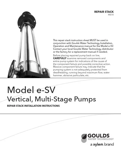
This repair stack instruction sheet MUST be used in conjunction with Goulds Water Technology Installation, Operation and Maintenance manual for the Model e-SV. Contact your local Goulds Water Technology distributor or the factory for a replacement manual if needed. Before placing repaired pump back on line, CAREFULLY examine removed components andentire pump system for indications of the cause ofthe component failure and possible corrective action. Massive component failure may indicate that the pumping system is not adequately protected from deadheading, running beyond maximum flow, water hammer, abrasive particulate, etc.REPAIR STACKIM2352SAFETY INSTRUCTIONSFAILURE TO DISCONNECT ANDLOCKOUT ELECTRICAL POWER BE-FORE ATTEMPTING MAINTENANCE CAN CAUSE SEVERE PERSONAL IN-JURY .IF PUMPING HAZARDOUS OR TOXIC FLUIDS, SYSTEM MUST BE FLUSHED PRIOR TO PERFORMING SERVICE.PUMP STACK REMOVAL1. Close all necessary suction and discharge valves.2. Drain the liquid from the pump by removing the lower drain plug and the upper vent plug.3. Remove the coupling guards, the 4 coupling hex cap screws, the coupling and coupling drive pin.4. Remove the 4 motor hex cap screws. *On 33-125SV units with motor frames 213TC and larger and 1-22SV units with motor frames 280TC and larger, remove the 4 motor adapter flange hex cap screws.5. With an adequately sized crane, carefully remove the motor. DO NOT rest the motor on the motor shaft.6. Remove Seal Gland or Cartridge Seal• For 1-22SV units, remove the 4 socket head cap screws to lift and remove the seal gland.• For 33-125SV units without cartridge seal; 1. Remove the 4 socket head cap screws.2. Lift and remove the seal gland. If seal gland does not lift by hand, use the two tapped holes provided to loosen and lift the gland for removal.• For 33-125SV units with cartridge seal;1. Loosen the 4 set-screws located around the ID of the pump shaft.2. Remove the 4 socket head cap screws.3. Remove the cartridge seal using the two tapped holes provided on the gland of the cartridge seal by threading two of the hex cap screws into these holes and evenly tightening these screws..4. Once loosened, lift and remove the cartridge seal.7. Remove the 4 tie rod nuts and washers.8. Remove Motor Adapter / Motor adapter assembly and upper seal plate• For 1-22SV units lift the motor adapter to remove. *Note that the upper seal plate may remove with the motor adapter when lifting. If the upper seal plate remains on the pump casing, lift to remove.• For 33-125SV units, lift the motor adapter assembly (motor adapter and top seal plate). A crane may be required to safely lift the motor adapter assembly.9. Remove the pump stack, grasp the pump shaft, rock side to side to free the stack, then lift vertically. If the first stage bowl remained in the pump body, CARE-FULLY pry up the bowl and remove.REPAIR STACK INSTALLATION1. Inspect and clean the inside of the pump body, re-moving any debris.2. Remove repair stack from packaging, inspect fordamage and clean, removing any tape used to holdcomponents together.3. Grasp shaft of repair stack and lower into the pumpbody. Center the stack within the pump body untilthe first stage seats in the bottom. Push down onstack to lock in place.4. Replace O-ring in top groove in casing.5. Re-install the upper seal plate and motor adapter• For 1-22SV units place the upper seal plate squarely on top of the pump casing and press down firmly.The seal plate should seat firmly and the o-ringshould remain in the casing groove. Once upperseal plate is installed the motor adapter can beplaced on top of the assembly and aligned as origi-nally installed.• For 33-125SV units, lift the motor adapter as-sembly (motor adapter and top seal plate) andplace squarely on top of the pump casing, alignedas originally installed. A crane may be required tosafely lift the motor adapter assembly.6. Reinstall Tie Rods, Nuts, and W ashers (see “T orqueValues” for appropriate tightening torque). The tie-rod nuts should be tightened in small increments in a diagonal pattern to ensure it seats properly. Pay close attention to ensure that the casing o-ring remains inthe casing groove.7. Reinstall Seal Gland or Cartridge Seal• For 1-22SV units, remove the used stationary sealface from the seal gland.1. Remove the used stationary seal seat from theseal gland.2. With a clean cloth wipe the seal bore and inspectfor damage; replace seal gland if damaged.3. Insert the new stationary seal seat into the sealbore of the seal gland with the seal face out. DONOT scratch or damage the seal face. Ensurethat the seal is seated firmly and squarely insidethe seal bore. With a clean lint-free cloth or alco-hol swab wipe the seal face clean of all lubricantor debris. DO NOT use grease or heavy lubri-cants to install seal, as these materials can causethe seal to leak.4. Replace o-ring on seal gland.5. Install the rotating portion of the seal onto thepump shaft, seating the plate fully and squarely.6. Re-install the 4 socket head cap screws (see“T orque Values” for appropriate tighteningtorque). The screws should be tightened in smallincrements in a diagonal pattern to ensure theseal gland seats properly.• For 33-125SV units without cartridge seal;1. Remove the used stationary seal seat from theseal gland.2. With a clean cloth wipe the seal bore and inspectfor damage; replace seal gland if damaged.3. Insert the new stationary seal seat into the sealbore of the seal gland with the seal face out. DONOT scratch or damage the seal face. Ensurethat the seal is seated firmly and squarely insidethe seal bore. With a clean lint-free cloth or alco-hol swab wipe the seal face clean of all lubricantor debris. DO NOT use grease or heavy lubri-cants to install seal, as these materials can causethe seal to leak.4. Rotate the rotary portion of the mechanical sealon the pump shaft until it “locks” and you areunable to turn freely. If you are unable to turninitially, the seal is seated properly.5. Replace o-ring on seal gland.6. Install the seal gland onto the pump shaft, seat-ing the plate fully and squarely.7. Re-install the 4 socket head cap screws (see“T orque Values” for appropriate tighteningtorque). The screws should be tightened in smallincrements in a diagonal pattern to ensure theseal gland seats properly.• For 33-125SV units with cartridge seal;1. Replace the o-ring on the cartridge seal.2. Slide the cartridge seal assembly along the pumpshaft into position and alignment with boltholes. Seat the cartridge seal squarely and firmly.3. Re-install the 4 socket head cap screws (see“T orque Values” for appropriate tighteningtorque). The screws should be tightened in smallincrements in a diagonal pattern to ensure theseal gland seats properly.8. Reinstall the coupling pin and locate the spacer shimon the shaft, resting on the seal gland or cartridgeseal. If the shim is not available, a 5mm shim can be used.9. Lower the motor slowly onto the motor adapter andalign the motor shaft with the coupling and motormounting holes. Reinstall the 4 motor hex cap screws (see "T orque Values" for appropriate tighteningtorque) to secure motor to motor adapter.10. Reinstall the coupling halves evenly to maintain aconsistent gap on either side of the coupling halves.The coupling halves should not touch. T orque thecoupling bolts to the appropriate values defined in“T orque Values”.11. Remove the spacer shim and save for future use.12. FOR 33-125SV PUMPS WITH CARTRIDGE SEALONLY; tighten the 4 set screws on the shaft collar.3GOULDS WATER TECHNOLOGY LIMITED WARRANTYThis warranty applies to all water systems pumps manufactured by Goulds W ater T echnology.Any part or parts found to be defective within the warranty period shall be replaced at no charge to the dealer during the warranty period. The warranty period shall exist for a period of twelve (12) months from date of installation or eighteen (18) months from date of manufacture, whichever period is shorter.A dealer who believes that a warranty claim exists must contact the authorized Goulds W ater T echnology distributor from whom the pump was purchased and furnish complete details regarding the claim. The distributor is authorized to adjust any warranty claims utilizing the Goulds W ater T echnology Customer Service Department.The warranty excludes:(a) Labor, transportation and related costs incurred by the dealer;(b) Reinstallation costs of repaired equipment;(c) Reinstallation costs of replacement equipment;(d) Consequential damages of any kind; and,(e) Reimbursement for loss caused by interruption of service.For purposes of this warranty, the following terms have these definitions:(1) “Distributor” means any individual, partnership, corporation, association, or other legal relationship that stands between Goulds W ater T echnology and the dealer inpurchases, consignments or contracts for sale of the subject pumps.(2) “Dealer” means any individual, partnership, corporation, association, or other legal relationship which engages in the business of selling or leasing pumps to customers.(3) “Customer” means any entity who buys or leases the subject pumps from a dealer. The “customer” may mean an individual, partnership, corporation, limited liabilitycompany, association or other legal entity which may engage in any type of business.THIS WARRANTY EXTENDS TO THE DEALER ONLY .TORQUE VALUESHP Motor BoltAdapter FlangeCoupling1-5SV 10-22SV 33-125SV0.5-7.5 HP 20 lbs ft (27 N m) —15 lbs ft (20 N m) 40 lbs ft (54 N m) 37 lbs ft (50 N m) 10-75 HP45 lbs ft (61 N m)48 lbs ft (65 N m)*15 lbs ft (20 N m)40 lbs ft (54 N m)48 lbs ft (65 N m)*213TC and 215TC Adapter Flange use 30 lbs ft (40 N m)Pump Size Tie Rod Nuts Vent / Drain Plug 1-5SV 22 lbs ft (30 N m) 15 lbs ft (20 N m) 10-22SV37 lbs ft (50 N m)15 lbs ft (20 N m) 33-125SV 44 lbs ft (60 N m)29 lbs ft (40 N m)Seal Gland [lbs ft (N m)]1-22SV 33-125SV18 lbs ft (25 N m)37lbs ft (50 N m)Goulds is a registered trademark of Goulds Pumps, Inc. and is used under license.© 2012 Xylem Inc. IM235 Revision Number 1 July 2012Xylem, Inc.2881 East Bayard Street Ext., Suite A Seneca Falls, NY 13148Phone: (800) 453-6777 Fax: (888) 322-5877/brands/gouldswatertechnology。
IMPORTANT SAFETY NOTICETo: Our Valued CustomersUser safety is a major focus in the design of our products. Following the precautions outlined in this manual will minimize your risk of injury.ITT Goulds pumps will provide safe, trouble-free service when properly installed, maintained, and operated.Safe installation, operation, and maintenance of ITT Goulds Pumps equipment are an essential end user responsibility. This Pump Safety Manual identifies specific safety risks that must be considered at all times during product life. Understanding and adhering to these safety warnings is mandatory to ensure personnel, property, and/or the environment will not be harmed. Adherence to these warnings alone, however, is not sufficient — it is anticipated that the end user will also comply with industry and corporate safety standards. Identifying and eliminating unsafe installation, operating and maintenance practices is the responsibility of all individuals involved in the installation, operation, and maintenance of industrial equipment.Please take the time to review and understand the safe installation, operation, and maintenance guidelines outlined in this Pump Safety Manual and the Instruction, Operation, and Maintenance (IOM) manual. Current manuals are available at /literature_ioms.html or by contacting your nearest Goulds Pumps sales representative.These manuals must be read and understood before installation and start-up.For additional information, contact your nearest Goulds Pumps sales representative or visit our Web site at .SAFETY WARNINGSSpecific to pumping equipment, significant risks bear reinforcement above and beyond normal safety precautions.WARNINGA pump is a pressure vessel with rotating parts that can be hazardous. Any pressure vessel can explode,rupture, or discharge its contents if sufficiently over pressurized causing death, personal injury, property damage, and/or damage to the environment. All necessary measures must be taken to ensure overpressurization does not occur.WARNINGOperation of any pumping system with a blocked suction and discharge must be avoided in all cases.Operation, even for a brief period under these conditions, can cause superheating of enclosed pumpage and result in a violent explosion. All necessary measures must be taken by the end user to ensure this condition is avoided.WARNINGThe pump may handle hazardous and/or toxic fluids. Care must be taken to identify the contents of the pump and eliminate the possibility of exposure, particularly if hazardous and/or toxic. Potential hazards include, but are not limited to, high temperature, flammable, acidic, caustic, explosive, and other risks.WARNINGPumping equipment Instruction, Operation, and Maintenance manuals clearly identify accepted methods for disassembling pumping units. These methods must be adhered to. Specifically, applying heat to impellers and/or impeller retaining devices to aid in their removal is strictly forbidden. Trapped liquid can rapidly expand and result in a violent explosion and injury.ITT Goulds Pumps will not accept responsibility for physical injury, damage, or delays caused by a failure to observe the instructions for installation, operation, and maintenance contained in this Pump Safety Manual or the current IOM available at /literature.SAFETYDEFINITIONSThroughout this manual the words WARNING, CAUTION, ELECTRICAL, and ATEX are used to indicate where special operator attention is required.Observe all Cautions and Warnings highlighted in this Pump Safety Manual and the IOM provided with your equipment.WARNINGIndicates a hazardous situation which, if not avoided, could result in death or serious injury.Example:Pump shall never be operated without coupling guard installed correctly.CAUTIONIndicates a hazardous situation which, if not avoided, could result in minor or moderate injury.Example: Throttling flow from the suction side may cause cavitation and pump damage.ELECTRICAL HAZARDIndicates the possibility of electrical risks if directions are not followed.Example:Lock out driver power to prevent electric shock, accidental start-up, and physical injury.When installed in potentially explosive atmospheres, the instructions that follow the Ex symbol must be followed. Personal injury and/or equipment damage may occur if these instructions are not followed. If there is any question regarding these requirements or if the equipment is to be modified, please contact an ITT Goulds Pumps representative before proceeding.Example: Improper impeller adjustment could cause contact between the rotating and stationaryparts, resulting in a spark and heat generation.GENERAL PRECAUTIONSWARNINGA pump is a pressure vessel with rotating parts that can be hazardous. Hazardous fluids may be contained by the pump including high temperature, flammable, acidic, caustic, explosive, and other risks. Operators andmaintenance personnel must realize this and follow safety measures. Personal injuries will result if procedures outlined in this manual are not followed. ITT Goulds Pumps will not accept responsibility for physical injury, damage or delays caused by a failure to observe the instructions in this manual and the IOM provided with your equipment.General PrecautionsWARNINGNEVER APPLY HEAT TO REMOVE IMPELLER. It may explode due to trapped liquid. WARNINGNEVER use heat to disassemble pump due to risk of explosion from tapped liquid. WARNINGNEVER operate pump without coupling guard correctly installed. WARNING NEVER run pump below recommended minimum flow when dry, or withoutprime.WARNING ALWAYS lock out power to the driver before performing pump maintenance.WARNING NEVER operate pump without safety devices installed.WARNING NEVER operate pump with discharge valve closed.WARNING NEVER operate pump with suction valve closed.WARNING DO NOT change service application without approval of an authorized ITTGoulds Pumps representative.WARNING Safety Apparel:Insulated work gloves when handling hot bearings or using bearing heaterHeavy work gloves when handling parts with sharp edges, especiallyimpellersSafety glasses (with side shields) for eye protectionSteel-toed shoes for foot protection when handling parts, heavy tools, etc.Other personal protective equipment to protect against hazardous/toxic fluidsWARNING Receiving:Assembled pumping units and their components are heavy. Failure to properly liftand support equipment can result in serious physical injury and/or equipmentdamage. Lift equipment only at specifically identified lifting points or asinstructed in the current IOM. Current manuals are available at/literature_ioms.html or from your local ITT GouldsPumps sales representative. Note: Lifting devices (eyebolts, slings, spreaders, etc.)must be rated, selected, and used for the entire load being lifted.WARNINGAlignment:Shaft alignment procedures must be followed to prevent catastrophic failure ofdrive components or unintended contact of rotating parts. Follow couplingmanufacturer’s coupling installation and operation procedures.General PrecautionsWARNING Before beginning any alignment procedure, make sure driver power is locked out.Failure to lock out driver power will result in serious physical injury.CAUTION Piping:Never draw piping into place by forcing at the flanged connections of the pump.This may impose dangerous strains on the unit and cause misalignment betweenpump and driver. Pipe strain will adversely effect the operation of the pumpresulting in physical injury and damage to the equipment.WARNING Flanged Connections:Use only fasteners of the proper size and material.WARNING Replace all corroded fasteners.WARNING Ensure all fasteners are properly tightened and there are no missing fasteners.WARNING Startup and Operation:When installing in a potentially explosive environment, please ensure that themotor is properly certified.WARNING Operating pump in reverse rotation may result in contact of metal parts, heatgeneration, and breach of containment.WARNING Lock out driver power to prevent accidental start-up and physical injury.WARNING The impeller clearance setting procedure must be followed. Improperly settingthe clearance or not following any of the proper procedures can result in sparks,unexpected heat generation and equipment damage.WARNING If using a cartridge mechanical seal, the centering clips must be installed and setscrews loosened prior to setting impeller clearance. Failure to do so could resultin sparks, heat generation, and mechanical seal damage.WARNING The coupling used in an ATEX classified environment must be properly certifiedand must be constructed from a non-sparking material.WARNING Never operate a pump without coupling guard properly installed. Personal injurywill occur if pump is run without coupling guard.WARNING Make sure to properly lubricate the bearings. Failure to do so may result in excessheat generation, sparks, and / or premature failure.CAUTION The mechanical seal used in an ATEX classified environment must be properlycertified. Prior to start up, ensure all points of potential leakage of process fluid tothe work environment are closed.CAUTION Never operate the pump without liquid supplied to mechanical seal. Running amechanical seal dry, even for a few seconds, can cause seal damage and must beavoided. Physical injury can occur if mechanical seal fails.WARNING Never attempt to replace packing until the driver is properly locked out and thecoupling spacer is removed.WARNING Dynamic seals are not allowed in an ATEX classified environment.WARNINGDO NOT operate pump below minimum rated flows or with suction and/ordischarge valve closed. These conditions may create an explosive hazard due tovaporization of pumpage and can quickly lead to pump failure and physical injury.General PrecautionsWARNINGEnsure pump is isolated from system and pressure is relieved beforedisassembling pump, removing plugs, opening vent or drain valves, ordisconnecting piping.WARNINGShutdown, Disassembly, and Reassembly:Pump components can be heavy. Proper methods of lifting must be employed toavoid physical injury and/or equipment damage. Steel toed shoes must be worn atall times.WARNINGThe pump may handle hazardous and/or toxic fluids. Observe properdecontamination procedures. Proper personal protective equipment should beworn. Precautions must be taken to prevent physical injury. Pumpage must behandled and disposed of in conformance with applicable environmentalregulations.WARNINGOperator must be aware of pumpage and safety precautions to prevent physicalinjury.WARNING Lock out driver power to prevent accidental startup and physical injury. CAUTIONAllow all system and pump components to cool before handling them to preventphysical injury.CAUTIONIf pump is a Model NM3171, NM3196, 3198, 3298, V3298, SP3298, 4150, 4550,or 3107, there may be a risk of static electric discharge from plastic parts that arenot properly grounded. If pumped fluid is non-conductive, pump should bedrained and flushed with a conductive fluid under conditions that will not allowfor a spark to be released to the atmosphere.WARNINGNever apply heat to remove an impeller. The use of heat may cause an explosiondue to trapped fluid, resulting in severe physical injury and property damage. CAUTIONWear heavy work gloves when handling impellers as sharp edges may causephysical injury.CAUTIONWear insulated gloves when using a bearing heater. Bearings will get hot and cancause physical injury.ATEX CONSIDERATIONS and INTENDED USESpecial care must be taken in potentially explosive environments to ensure that the equipment is properly maintained. This includes but is not limited to:1. Monitoring the pump frame and liquid end temperature.2. Maintaining proper bearing lubrication.3. Ensuring that the pump is operated in the intended hydraulic range.The ATEX conformance is only applicable when the pump unit is operated within its intended use. Operating, installing or maintaining the pump unit in any way that is not covered in the Instruction, Operation, and Maintenance manual (IOM) can cause serious personal injury or damage to the equipment. This includes any modification to the equipment or use of parts not provided by ITT Goulds Pumps. If there is any question regarding the intended use of the equipment, please contact an ITT Goulds representative before proceeding. Current IOMs are available at /literature_ioms.html or from your local ITT Goulds Pumps Sales representative.All pumping unit (pump, seal, coupling, motor and pump accessories) certified for use in an ATEX classified environment, are identified by an ATEX tag secured to the pump or the baseplate on which it is mounted. Atypical tag would look like this:The CE and the Ex designate the ATEX compliance. The code directly below these symbols reads as follows:II = Group 22 =Category2G/D = Gas and Dust presentT4 = Temperature class, can be T1 to T6 (see Table 1)Table 1CodeMax permissiblesurface temperatureo F (o C)Max permissibleliquid temperatureo F (o C)T1 842 (450) 700 (372)T2 572 (300) 530 (277)T3 392 (200) 350 (177)T4 275 (135) 235 (113)T5 212 (100) Option not availableT6 185 (85) Option not availableThe code classification marked on the equipment must be in accordance with the specified area where the equipment will be installed. If it is not, do not operate the equipment and contact your ITT Goulds Pumps sales representative before proceeding.PARTSThe use of genuine Goulds parts will provide the safest andmost reliable operation of your pump. ITT Goulds Pumps ISOcertification and quality control procedures ensure the parts aremanufactured to the highest quality and safety levels.Please contact your local Goulds representative for details ongenuine Goulds parts.S-8©2007 Goulds Pumps, Incorporated Form ITRASHHOGIIa subsidiary of ITT Corporation。
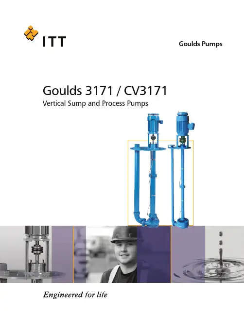
Goulds Pumps Goulds 3171 / CV3171Vertical Sump and Process PumpsModel 3171 Vertical Sump and Process PumpsHeavy Duty Design Features for a Wide Range of ServicesGoulds 31713LABYRINTH BEARING SEALPrevents premature bearing failure due to lubricant contamination.HEAVY COLUMN PIPEProvides rigid support for pump and bearings.LINESHAFT STEADY BEARING Self-lubricating carbon/graphite bearing furnished as standard—best for handling water,corrosives, solvents and high temperature liquids.RESTRICTOR BUSHINGClose running bushing to prevent pressure loss from casing.FULL Y OPEN IMPELLERWITH BACK PUMP-OUT VANES Acknowledged best design for process services—solids handling,stringy material, corrosives,abrasives.C-FACE MOTOR MOUNTING Accommodates readily available C-face motors. Also available forP-base and IEC motors.CONTINUOUS HIGH PERFORMANCE Original high efficiency maintained by simple external adjustment resultingin long-term energy savings.DOUBLE ROW THRUST BEARINGGrease lubricated—carries pump thrust load; sealed for outdoorinstallation.DISCHARGE LOCKED TO PUMP SUPPORT PLATEFOR STRENGTHANY MOUNTING REQUIREMENTS Met by support plate and optional pit cover. Float switches, alternators and other control devices can beeasily mounted.STEADY BEARING HOUSING Precision machined register fit of column, bearing housing and casing assures positive bearing andshaft alignment. Completely interchangeable with all lineshaftbearing options.HEAVY DUTY ONE-PIECE SHAFTWith closely spaced steady bearingsassures long life and lowmaintenance.HEAVY DUTY CASINGProvides rigid support for shaft–closer to impeller load–resulting in longersteady bearing life.REMOVABLE SUCTION COVER Replaceable wear part for lowoperational costs.OPTIONAL UPPER STUFFING BOXGoulds sealed bearing recommended for applications where are in the pumpage for sealing the bearing housing. Spring loaded grease cup is provided.Optional Features for Application FlexibilityGoulds offers a variety of options to meet users’ specific plant and application requirements. Your Gouldsrepresentative will be glad to recommend the featuresbest suited to your particular service conditions to assure safe, efficient and reliable operation.SEALED BEARING ARRANGEMENTJACKETED COLUMNJACKETED DISCHARGEGoulds offers the best choice of steady bearings to meet service requirements...optional fluted rubber with rigid shell, bronze,and (standard) carbon.56Maximum Sealing FlexibilityVapor-Proof ConstructionOptional upper stuffing box allows use of wide rangeof sealing arrangements to meet specific user requirements for sealing toxic, hazardous, noxious or corrosive fumes.With this option, the discharge pipe and all fittings are sealed at the support plate.Your Goulds representative will gladly recommend the best sealing solution for your service, some of which are illustrated here.PACKED BOX Standard vapor-proof sealing option. Includes packing, lantern ring and grease lubricator (not illustrated).DRY RUNNING SEALDry running, non-contacting cartridge gas seal.Pressurized air barrier between seal facesprevents vapor leakage.SINGLE OUTSIDE SEALMechanical seal with oil lubricator and sight glass.Outside mount has no metal parts in contact with vapors.DOUBLECARTRIDGE SEAL Available in wet or dry versions to control emissions.Dimensions Model 3171All dimensions in inches and (mm). Not to be used for construction.*Add 3 in. (76) for float mounted option.78240134242189122195192123190197178182315187332A136213155199100198101351Designed to Meet (or Exceed) T oday’s T ough Environmental Requirements Installed in 1988 on hydrocarbon waste sump service, this 3171 was easilyretrofitted with vapor-proof construction including a ferrofluidic seal (see page 7)to meet tougher EPA emissionrequirements. Readings were less than 30 ppm—exceeding EPA requirementsOptional Upper Stuffing BoxSectional View Model 31719Goulds CV 3171LABYRINTH BEARING SEALPrevents premature bearing failure due to lubricant contamination.HEAVY COLUMN PIPEProvides rigid support for pump and bearings.LINESHAFT STEADY BEARINGGrease lubricating sealed bearings furnished as standard—best for handling fluids with solids.RESTRICTOR BUSHINGClose running bushing to prevent pressure loss from casing.RECESSED IMPELLERSince impeller is recessed in the casing, velocities are low and solids contact with the casing are reduced.Wear rate, solids degradation, and shearing of liquids are minimized.OPTIONAL STRAINERRecommended for services where solids larger than the discharge of the pump can potentially enter the casing.C-FACE MOTOR MOUNTING Accommodates readily available C-face motors. Also available forP-base and IEC motors.CONTINUOUS HIGH PERFORMANCE Original high efficiency maintained by simple external adjustment resultingin long-term energy savings.DOUBLE ROW THRUST BEARINGGrease lubricated—carries pump thrust load; sealed for outdoorinstallation.DISCHARGE LOCKED TO PUMP SUPPORT PLATEFOR STRENGTHANY MOUNTING REQUIREMENTS Met by support plate and optional pit cover. Float switches, alternators and other control devices can beeasily mounted.STEADY BEARING HOUSING Precision machined register fit of column, bearing housing and casing assures positive bearing andshaft alignment. Completely interchangeable with all lineshaftbearing options.HEAVY DUTY ONE-PIECE SHAFTWith closely spaced steady bearingsassures long life and lowmaintenance.NON-CLOG CIRCULAR CASING Large open passageways prevent clogging when handling bulky,fibrous, or stringy liquids. Circular Volute reduces radial loads during lowflow operation, extending steadybearing life.OPTIONAL UPPER STUFFING BOX11Model CV 3171 Vertical Sump and Process PumpsHeavy Duty Design Features for a Wide Range of ServicesCV 3171 Parts List and Materials of Construction1213Sectional View Model CV 3171221107105106240136242189122195333H 190197315351A332A134112333369A 192123213369306155108A 351412A 101100187Upper Stuffing Box14Dimensions Model CV 3171All dimensions in inches and (mm). Not to be used for construction.*Add 3 in. (76) for float mounted option.15PumpSmart ®is the latest advancement in pump control and protection to reduce energy consumption, increase uptime and decrease maintenance cost. It allows the pump to be right-sized to the application by dialing in the speed and torque whichincreases flow economy, reduces heat and vibration, and improves overall system reliability. •Simplified Pump Control — PumpSmart was designed specifically to optimize pumping applications and can be used to control a single pump or coordinate between multiple pumps without the need for an external controller.•Pump Protection — PumpSmart guarantees to protect the pump from upset conditions with patented sensorless pump protection algorithms.•Smart Flow — PumpSmart features a sensorless flow function for centrifugalpumps that can calculate the flow of the pump within ±5% of the pump rated flow. •Drive for the DCS — While most VFDs can only provide basic information,PumpSmart offers unparalleled insight to the pump operation which allows for smoother process control and efficiency.•Pump Experts — PumpSmart is a variable speed drive with pump-specific algorithms imbedded into the drive. With over 150 years of pump knowledge,let the pump experts take responsibility of your pump system.PUMP SMARTVisit our Web site at in the world. By identifying and alerting you to changes in operating conditions, ProSmart increases your time to respond to either correcting Form B3171/CV3171 10/08© 2008 Goulds Pumps, Incorporated A subsidiary of ITT Corporation, Inc.。
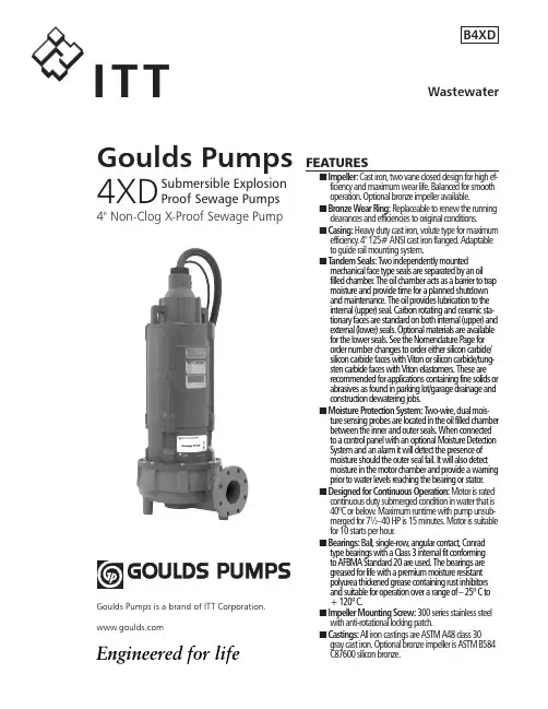
Goulds Pumps4XDSubmersible Explosion Proof Sewage Pumps4" Non-Clog X-Proof Sewage PumpFEATURESn Impeller: Cast iron, two vane closed design for high ef-ficiency and maximum wear life. Balanced for smooth operation. Optional bronze impeller available.n Bronze Wear Ring: Replaceable to renew the running clearances and efficiencies to original conditions.n Casing: Heavy duty cast iron, volute type for maximum efficiency . 4" 125# ANSI cast iron flanged. Adaptable to guide rail mounting system.n T andem Seals: T wo independently mounted mechanical face type seals are separated by an oil filled chamber . The oil chamber acts as a barrier to trap moisture and provide time for a planned shutdown and maintenance. The oil provides lubrication to the internal (upper) seal. Carbon rotating and ceramic sta-tionary faces are standard on both internal (upper) and external (lower) seals. Optional materials are available for the lower seals. See the Nomenclature Page for order number changes to order either silicon carbide/silicon carbide faces with Viton or silicon carbide/tung-sten carbide faces with Viton elastomers. These are recommended for applications containing fine solids or abrasives as found in parking lot/garage drainage and construction dewatering jobs.n Moisture Protection System: T wo-wire, dual mois-ture sensing probes are located in the oil filled chamber between the inner and outer seals. When connected to a control panel with an optional Moisture Detection System and an alarm it will detect the presence of moisture should the outer seal fail. It will also detect moisture in the motor chamber and provide a warning prior to water levels reaching the bearing or stator .n Designed for Continuous Operation: Motor is rated continuous duty submerged condition in water that is 40ºC or below . Maximum runtime with pump unsub-merged for 7½–40 HP is 15 minutes. Motor is suitable for 10 starts per hour .n Bearings: Ball, single-row , angular contact, Conrad type bearings with a Class 3 internal fit conforming to AFBMA Standard 20 are used. The bearings are greased for life with a premium moisture resistant polyurea thickened grease containing rust inhibitors and suitable for operation over a range of – 25º C to + 120º C.n Impeller Mounting Screw: 300 series stainless steel with anti-rotational locking patch.n Castings: All iron castings are ASTM A48 class 30 gray cast iron. Optional bronze impeller is ASTM B584 C87600 silicon bronze.Goulds Pumps is a brand of ITT Engineered for life2U L UnderwritersLaboratories MOTOR LISTED EXPLOSION PROOFCLaSS I, DIvISION I, GROuPS C & DAPPLICATIONS• Sewage systems• Flood and pollution control• Industrial dewatering• Wastewater treatment plants• Municipal and subdivision lift stations SPECIFICATIONSPump:• Solids handling capabilities: 3" maximum.• Discharge size: 4" 125# ANSI flanged.• Capacities: up to 1160 GPM.• Total heads: up to 140 feet.• Minimum flow: 100 GPM.• Maximum flow: end of published curve.• Mechanical seals: 304 stainless steel metal parts, BUNA- N elastomers with carbon/rotary and ceramic/stationary faces standard for upper and lower seals. Optional lower seals are available with Viton elastomers and either silicon carbide/ silicon carbide or silicon carbide/tungsten carbide faces.• Fasteners: 300 series stainless steel.Motor:•Explosion Proof Motor: Motors up to and including 40 HP are rated as Class F, 1.15 service factor and are certified explosion proof for Class I, Division I, Groups C and D locations.•CSA certified motors (Canadian Standards Association).•UL (Underwriters Laboratories) Listed Motors.•Three phase motors only.•Available voltages: 200, 230, 400, 460 and 575 volt, 60 Hz.•HP Range: 7.5 - 40.•Motor shaft is a one-piece design of high strength 416 stainless steel.•All motors are air-filled and designed for continuous duty when fully submerged or for up to 15 minutes operation in air.•NEMA design “B” with copper windings.•Class “F” stator winding designed for inverter duty.•Moisture System: Two wire dual probe monitoring system constantly monitors seal oil chamber and stator housing for moisture. Note: control panel must contain an alarm circuit and alarm device.•Two (2) normally-closed, automatic reset thermostats connected in series and embedded in adjoining phases.•Power and sensor cords are 25’ standard length, 50’ available as an option.•Motors conform to the latest applicable requirements of NEMA, IEEE, ANSI and NEC standards.NOTICE: Class 10 quick trip overload protection must be provided in control panel.1st Character – Discharge Size4 = 4” 125 # ANSI Discharge Flange2nd and 3rd Character – Pump Type / DesignXD = Explosion Proof, Dual Seal Pump with On-Winding Thermal Sensors and Moisture Detection Sensors 4th Character – Mechanical Seals1 = Standard Seal – the upper seal is carbon/ceramic,the lower seal is carbon/ceramic, BUNA and 304stainless steel metal parts.3 = Optional Lower Seal – silicon carbide/siliconcarbide, Viton elastomers and 304 SS metal parts.5 = Optional Lower Seal – silicon carbide/tungstencarbide, Viton elastomers and 304 SS metal parts. 5th Character – Motor RPM / Hertz2 = 1750 RPM / 60 Hz 6 = 1450 RPM / 50 Hz3 = 1150 RPM / 60 Hz6th Character – HorsepowerK = 7.5 M= 15 P = 25 R = 40L = 10 N = 20 Q = 307th Character – Voltage / Phase2 = 200 /34 = 460 / 3 6 = 380/400 / 33 = 230 / 3 5 = 575 / 38th Character – Impeller CodeA = 11.0” 10 HP 1150 RPM 40 HP 1750 RPM20 HP 1450 RPMB = 10.75” 30 HP 1750 RPMC = 10.38” 25 HP 1750 RPMD = 10.12” 7.5 HP 1150 RPM 15 HP 1450 RPME = 9.75” 20 HP 1750 RPMG = 9.00” 15 HP 1750 RPM 10 HP 1450 RPM K = 8.00” 10 HP 1750 RPM 7.5 HP 1450 RPM M = 7.50” 7.5 HP 1750 RPMT = SPECIAL TRIM9th Character – Cord Length - Power and Sensor Cords C = 25’ standard F = 50’ Optional10th Character – OptionsB = Silicon Bronze Impeller E = Epoxy PaintF = Both Bronze Impeller and Epoxy PaintNOMENCLATURE DESCRIPTIONSERIES 4XD(all ratings at 3 phase, 60 Hz. Consult factory for 3 phase, 50 Hz applications.)3Goulds Pumps and the ITT Engineered Blocks Symbol are registered trademarks and tradenames of ITT Corporation.SPECIFICaTIONS aRE SuBJECT TO CHaNGE WITHOuT NOTICE.B4XD August, 2008© 2008 ITT CorporationEngineered for lifeMaximum Solid Size3"Minimum Casing Thickness 5⁄16"Casing Corrosion Allowance 1⁄8"Maximum Working Pressure 100 PSI Maximum Submergence 200 feetMaximum Environmental Temperature40º C or 104º F ambient conditions.Maximum Starts Per Hour Maximum of 10 evenly spaced starts per hour.APPLICATION DATAPower Cable Type 1/0 / 4, 2/4, 4/4, 6/4, 8/4, 10/4, 12/4 SOW or SOOW(see Model Info).Control / Sensor Cable / Type 18/5 SOW.Power Cable and Leads have a BUNA N grommet in addition to being Cap Assembly epoxy encapsulated.Power and Control 25’ standard, 50’ optional.Cable Lengths Motor Enclosure Cast iron ASTM A-48 Class 30.Motor Shaft Series 416 Stainless steel.NEMA design “B” with copper windings and designed to Motor Designwithstand 200 psi water pressure at all seal locations. Air- filled NEMA 210TY frame on 7.5, 10, 15 and 20 HP models.Air-filled NEMA 250TYS frame on 25 - 40 HP models.Motor Insulation Rating Class "F" insulation.Motor Thermal Protection Two (2) normally closed on-winding thermostats open at320º F (160º C), automatic reset closes at 221º F (105º C).Motor Overload Protection Class 10, ambient compensated, quick-trip overloadprotection must be provided in control panel.Motor Moisture Protection Two (2) moisture sensing probes in the oil-filled sealchamber must be connected to a relay in control panel.CasingCast iron ASTM A-48 Class 30.Impeller Cast iron ASTM A-48 Class 30 or optional cast bronzeASTM B584 UNS C87600.Impeller TypeTwo vane enclosed design for maximum efficiency.Casing/Impeller/Wear Ring Replaceable bronze wear ring.External HardwareStainless steel.CONSTRUCTION DETAILSSTANDARD PARTSBall BearingsLubricated for life bearings are designed for aminimum L10 life of 30,000 hours .210 and 250 FrameSingle row Radial (upper). Single row Thrust (lower).Mechanical Seals – Upper Carbon/rotary and ceramic/stationary.Standard Lower Carbon/rotary and ceramic/stationary.Mechanical Seals – Lower Silicon carbide/rotary and tungsten carbide/stationary.Optional Lower Silicon carbide/rotary and silicon carbide/stationary.Standard Motor O-rings BUNA-N (nitrile)Premium moisture resistant polyurea thickened grease Seal Chamber Oil containing rust inhibitors is suitable for operation over a temperature range of - 25º C to +120º C.DIMENSIONS(All dimensions are in inches.Do not use for construction purposes.)。
Effective: 07-28-2023 Replaces: 02-26-2021 P/N 241295 Rev. 7SUPPLEMENTAL INSTALLATION AND OPERATING INSTRUCTIONSFor Hi Delta Models H 302CD-2342CD WH 302CD-2342CD P 992CD-2342CDIMPORTANT SAFETY INSTRUCTIONS. READ AND FOLLOW ALL INSTRUCTION. SAVE THESE INSTRUCTIONS.Patent No. 6,904,873FlexGas®Revision 7 reflects the following changes:Added two warnings regarding carbon monoxide to "Warnings" section per ANSI Z21.13_22 Chapters 4.33.1 b and 4.34 i. 2CONTENTSWarnings (4)Model Identification (5)Ratings and Certifications (5)Component Locations (6)Installation Codes (6)Gas Supply..............................................................6Bleed Vents . (7)Start up (8)FlexGas System Start Up (9)FlexGas Operation (10)Wiring Diagram (11)Illustrated Parts List (12)THIS INSTALLATION MANUAL MAY NOT BE THE LATEST REVISION PRINTED AT THE TIME OF PRODUCT SHIPMENT. VISIT THE RAYPAK WEBSITE TO VERIFY THE MANUAL DELIVERED WITH YOUR RAYPAK UNIT IS THE MOST UP-TO-DATE VERSION.34WARNINGSPay Attention to These Terms.56Figure 2. Gas Supply Connection - Top ViewGas Supply PressureA minimum of 5.6 in. WC and a maximum of 10.5 in. WC upstream gas pressure is required under load and no-load conditions for natural gas. A minimum of 11.0 in. WC and a maximum of 13.0 in. WC is required for propane gas. The gas pressure regulator(s) supplied on the heater is for low-pressure service. If upstream gas pressures exceed 14.0 in. WC, intermediate gas pressure regulators, of the lockup type, must be installed.When connecting additional gas utilization equipment to the gas piping system, the existing piping must be checked to determine if it has adequate capacity for the combined load.The gas valve pressure regulator(s) on the Hi Delta heater are nominally preset at 3.5 in. WC. The pressure regulator on the FlexGas propane system is nominally set at 2.2 ± 0.1 in. WC. This can be verified by measuring the propane gas pressure at the upper manifold pressure tap shown in Figure 4. The pressure at the gas valve(s) outlet tap, measured with a manometer, while in operation should be 3.5 ± 0.1 in. WC for natural gas. A nominal pressure of 1.3 in. WC will be observed at the individual heater gas valve outlet taps on propane gas. See Figure 4 for gas pressure measurement locations.Bleeds/VentsThis FlexGas gas train is equipped with a propane gas regulator which may need to be vented to the outdoors as required by state and local codes. If the regulator is required to be vented, the cover must be removed and vent lines installed and ran to a suitable location outside the building in compliance with the NFGC. See Figure 3. Figure 3. FlexGas Cover Removal & Vent Locations78MODELS: 302CD - 902CD MODELS: 992CD - 2342CDGAS VALVE OUTLET TAPGAS VALVE OUTLET TAPStart-UpFor Your SafetyThis appliance has a hot surface igniter(s). It is equipped with an ignition device(s) which automatically lights the burners. Do not try to light the burners by hand.BEFORE OPERATING, smell all around the appliance area for gas. Be sure to smell near the floor because some gas is heavier than air and will settle on the floor.WHAT TO DO IF YOU SMELL GAS:• Do not try to light any appliance.• Do not touch any electrical switch; do not use any telephone in your building.• Immediately call your gas supplier from a neighbor’s telephone. Follow the gas supplier’s instructions.• If you cannot reach your gas supplier, call the fire department.•Use only your hand to push in or turn the gas control knob. Never use tools. If the knob will not turn by hand, do not try to repair it, call a qualified service technician. Forced or attempted repair may result in a fire or explosion.•Do not use this appliance if any part has been under water, immediately call a qualified service technician to inspect the appliance and to replace any part of the control system and any gas control which has been under water.•Check around unit for debris and remove combustible products, i.e. gasoline, etc.Pre Start-up Check1. Verify heater is filled with water.2. Check system piping for leaks. If found, repairimmediately.3. Vent air from system. Air in system can interfere withwater circulation.4.Purge air from gas lines up to FlexGas gas train.Initial Start-up Tools Needed:• (1) 12-0-12, 24" scale U-tube manometer • (4) 6-0-6, 12" scale U-tube manometers (min.)• (1) Screwdriver • (1) Multi-meter •(1) 3/16" Allen wrench9PreparationCheck Power Supply With multi-meter at incoming power in Hi Delta heater, check voltage between:Hot - Common (≈120 VAC)Hot - Ground (≈120 VAC)Common - Ground (< 1 VAC)Attach Manometers to Measure Pressures1. Turn off main gas valves.2. Attach 24" scale manometer to the first main gasshutoff valve pressure tapping.3. Attach (1) 12" scale manometer to the outlet side ofthe second main gas shutoff valve pressure tapping.4. Attach (1) 12" scale manometer near the fan-provingswitch. Pull black cap from air pressure switch tee and connect the manometer. NOTE : Retain caps for reinstallation later.Check Gas Supply Pressure1. Slowly turn on main gas shutoff valve.2. Read the gas supply pressure from the manometer;minimum supply pressure for natural gas is 5.6 in. WC, recommended supply is 7.0 in. WC, minimum supply pressure for propane gasis 11.0 in. WC(dynamic readings, all stages firing).3. If the pressure is > 14.0 in. WC, turn off the valve.4. Check if the service regulator is installed and/or adjust the service regulator.FlexGas System Start-up1. Turn off unit. Ensure that the switch on the FlexGascontrol is in the position marked “NAT”. See Figure 5 for FlexGas control operation. Ensure the manualvalve on the natural gas supply is open and the manual valve on the propane supply is closed.2. Turn on the unit, wait 15 seconds, and the igniter should glow. Look into sight glass located at eachend of the heater to check igniter operation. Gas valves should open in 45-60 seconds.3. If burner does not light on first trial. It will retry, up tothree times.4. Main burner ignition: Check manifold gas pressure atgas valve outlet pressure tap. This should read 3.5 ± 0.1 in. WC for natural gas. If the natural gas manifold pressure is not within 3.5 ± 0.1 in. WC, follow theinstructionsin the Hi Delta manual for adjustingmanifold pressure. If a flue gas analyzer is used,the CO2 on natural gas should be 7.5-8.5% and CO should be less than 150 ppm.5. When acceptable operation on Natural Gas is confirmed, turn the gas selector key on the FlexGas control to “OFF”.6. Close the manual valve on the natural gas supplythen open the manual valve on the propane supply. When the heater shuts off, turn the FlexGas control key counter-clockwise to the “PRO” position.7. Wait 15-seconds, and the igniter should glow. Lookinto sight glass located at each end of the heater tocheck igniter operation. Gas valves should open in45-60 seconds.8. If burner does not light on first trial. It will retry, up to three times.9. Main burner ignition: Check upper manifold gaspressure.10. If the pressure readings differ by more than ± 0.1in. WC, remove screw cover from the gas pressureregulator on the FlexGas fuel train and adjust untilupper manifold pressure is nominally 2.2 ± 0.1 in. WC (manifold pressure 1.3 ± 0.1 in. WC). If a flue gas analyzer is used, the CO2 on propane should be 9.0-10.0% and CO should be less than 150 ppm.1011. Replace the screw cover.12. Turn the gas selector key on the FlexGas controlpanel to “OFF”.13. Close the manual valve on the propane gas supplyand open the manual valve on the natural gas supply. Turn the gas selector key on the FlexGascontrol clockwise to “NAT”. The heater is now readyfor operation.FlexGas Operation - Changing FuelsFrom NAT to PRO:1. Turn the boiler off (power switch on front control panel).2. Turn FlexGas key to “OFF”.3. Close NAT manual valve.4. Open PRO manual valve.5. Turn FlexGas key to “PRO”.6. Turn the boiler on.From PRO to NAT:1. Turn the boiler off (power switch on front control panel).2. Turn FlexGas key to “OFF”.3. Close PRO manual valve.4. Open NAT manual valve.5. Turn FlexGas key to “NAT”.6. Turn the boiler on.Safety Inspection1. Check all thermostats and high limit settings.2. During the following safety checks leave manometers hooked up, check and record.3. If other gas-fired appliances in the room are on thesame gas main, check all pressures on the Hi Delta with all other equipment running.4. Check thermostats for ON-OFF operation.5. Check high limits for ON-OFF operation.6. While in operation, check flow switch operation.7. Check the low gas pressure switch (if so equipped). (For proper adjustment, use the attached manometers,if available, to set pressure. The scales on the switchare approximate only.) Low gas pressure switch must be set at 5.0 in. WC for natural gas.Follow-UpSafety checks must be recorded as performed.Turn heater on. After main burner ignition:1. Check manometer for proper reading.2. Cycle heater several times and re-check readings.3. Turn unit off.4. Remove all manometers and replace caps andscrews. 5. Replace all gas pressure caps.6. Check for gas leaks one more time.7. Restart unit.11Figure 5.FlexGas Control PanelFigure 6.Wiring Diagram1213Raypak, Inc. 2151 Eastman Avenue, Oxnard, CA 93030 (805) 278-5300 。
IM080R06TABLE OF CONTENTSSUBJECT PAGE Operating and Safety Instrutions (3)Maintenance Instructions (3)Recommended Precautions (3)Operating Instructions (4)Operating (4)General (4)Proper Location (4)Connections (4)Strainer Advisable (4)Starting (4)Lubrication (4)High Discharge (4)Maintenance (4)Troubleshooting Guide (5)Repair Parts (6)Limited Warranty (8)Please fill in data from your pump nameplate.Warranty information is on page 8.Pump Model:Serial Number:Dealer:Dealer’s Phone Number:Date of Purchase:Installation Date:2CongratulationsY ou are now the owner of a Goulds pump. This pump was carefully inspected and subjected to final tests before releas-ing for shipment. In order to assure maximum performance please follow the simple instructions in this manual.PUMPING OF VOLATILE PETROLEUMPRODUCTS CAN BE HAZARDOUS. FOR THIS REASON, EXTREME CARE MUST BE EXERCISED AND ALL OPERATING AND SAFETY INSTRUCTIONS STRICTLY ADHERED TO. FAILURE TO DO THIS CAN RESUL T IN A FIRE OR EXPLOSION. APPLICATION: This pump is designed to pump petro-leum products such as diesel fuel, jet fuel or gasolinein well-ventilated areas that do not contain potentially explosive fumes.This equipment should be operated only by personnel who have been thoroughly instructed as to the hazards involved and who are familiar with the following operat-ing and safety instructions.OPERATING AND SAFETY INSTRUCTIONS1. Use non-sparking tools when making pump connec-tions.2. Always securely connect the ground wire to a goodground on the tank being filled, before operating the pump.3. Do not operate the engine while filling the pump tankwith its initial priming liquid.4. Do not refill engine if running or hot.5. Do not pump liquids other than water or petroleumproducts.6. Do not operate with leaky seal or piping, closed suc-tion or discharge valve or with a fill plug removed. 7. Operate pump only with guard in place. MAINTENANCE INSTRUCTIONS1. If engine is hard to start, or runs rough, move unit to asafe area and check out on water.2. This engine must be maintained in original conditionthroughout its use. Prior to each use, inspect the aircleaner, spark arresting muffler, shielded spark plug, shielded spark plug wire, and the enclosed run-stop switch, to make certain that these are not worn ordamaged in any way.3. Use only original replacement parts - this is criticalsince each part was selected for its safety and highquality.RECOMMENDED PRECAUTIONS1. APPLICATION: This pump is designed to pumppetroleum products such as diesel fuel, jet fuel orgasoline in well-ventilated areas that do not containpotentially explosive fumes. Primarily intended forfuel transfer or refueling construction equipment atremote open air sites where the lack of electricitymakes it impossible to use pumps driven by explo-sion-proof electric motors.Pumping of volatile petroleum products can be haz-ardous. For this reason, extreme care must be exer-cised and all operating and safety instructions strictly adhered to.2. As with all self-priming centrifugal pumps, the pumptank must be initially filled with the liquid beingpumped. DO NOT run the engine while filling thepump tank. Failure to follow this precaution couldresult in a fire or explosion.3. This pump is designed primarily for water and petro-leum products use. Before pumping other liquids,carefully read the special note below.4. Do not subject the pump to a pressure in excess of75 psi.5. Should the fluid temperature rise more than 50ºF.ambient, expansion joints must be installed on both the suction and discharge ports to relieve any stress on the pump casing.6. No modifications, additions or deletions should bemade to the pump.7. Prime movers powering the pumps may operateat high temperatures. Keep hands off mufflers andmanifolds to avoid burns.8. In systems where shock wave pressures may begenerated, protective devices (check valve/gatevalve, etc.) must be installed on discharge line toprevent shock wave pressures from entering casing.A discharge check valve is required when operatingagainst high static heads.9. Do not refill engine fuel tank while power unit is run-ning or while hot. Prevent splashing of gasoline orother fuel while filling supply tank.10. Do not use in a combustible atmosphere.11. Make daily checks of the tightness of suction anddischarge pipe, drain, filler plug and pump gaskets.Check tightness of gasoline tank filler cap each time tank is filled. Operation should not proceed until allof the above items have been checked and are tight.The performance of Goulds WaterT echnology is based upon clear, cold, fresh water with suction conditions as shown on the performance curve. If used to pump other liquids, pump performance may differ from rated performance based on the different specific gravity, temperature, viscosity, etc. of the liquid being pumped. However, a standard pump may not be safe for pumping all types of liquids, such as toxic, volatile or chemical liquids, or liquids under extreme temperatures or pressures. Please consult your Goulds Water T echnology catalog as well as local codes and general references to determine the appropriate pumps for your particular application. Since it is impos-sible for us to anticipate every application of a Goulds pump, if you plan to use the pump for other than a water or petroleum product application, consult Goulds Water T echnology beforehand to determine whether such ap-plication may be proper or safe under the circumstances. Failure to do so could result in property damage or personal harm.THE INSTALLATION OF THE PUMPSHALL INCLUDE ADEQUATE DRAINAGE OR LOCATED SUCH THAT OTHER EQUIP-MENT OR PROPERTY WOULD NOT BE DAMAGED IN THE EVENT OF ANY LEAKAGE. THE PUMP SHOULD NOT BE INSTALLED ABOVE EQUIPMENT OR PROP-ERTY UNLESS ADEQUATE DRAINAGE IS PROVIDED. FAILURE TO COMPLY WITH THIS WARNING COULD RESULT IN PROPERTY DAMAGE.OVERTIGHTENING OF THE CASINGFASTENERS COULD DAMAGE THE FASTENER, RESULTING IN LEAKAGE ANDPROPERTY DAMAGE.3OPERATING INSTRUCTIONSGENERAL• Our shipping container has been specifically designed to prevent transit damage. However, any indications of damage or shortage should be carefully noted on the delivery ticket and a claim filed promptly with the car-rier.PROPER LOCATION• By placing your Goulds pump on a firm, level founda-tion, you reduce the chance of its falling into the liquid and damaging the engine. You also insure proper oil lubrication of the engine and obtain optimum engine performance. Best pump operation is obtained by locating the pump so as to minimize the suction lift as much as practical, keeping in mind that a pump can push liquid more effectively than it can pull or draw liquid.CONNECTIONS• Connections at the easily accessible suction and dis-charge ports can be made with either oil-resistant hose or pipe. The use of strongly reinforced suction hosewill prevent collapsing of the hose during operation. New hose washers should be used at the couplings to prevent trouble-causing leaks. Pipe joint compound that will not dissolve in the liquid being pumped should be used on all pipe joints. All hose or pipe should be inde-pendently supported to eliminate excessive strain on the pump. For best results your hose should discharge higher than the pump to prevent siphoning action when the unit is shut down.• We strongly recommend the use of extra-heavy close faced nipples on the suction and discharge ports ofthe 2AM32-P petroleum pump. Also, be sure to apply pipe compound on the nipples before installing. When pumping petroleum products, it is particularly important to use suitable hose, gaskets and fittings to minimize the chance of a leak occurring.• Also, be certain that the splash guard special air cleaner and spark arresting muffler are used on every applica-tion.STRAINER ADVISABLE• Protect your investment, use a strainer. Strainers are at-tached to the suction line to prevent stones and foreign debris from damaging the impeller or diffuser, result-ing in reduced performance. Stones lodged insidethe pump can cause premature wear and poor perfor-mance. T o keep the strainer from working into the sedi-ment, suspend the hose from the end of a rope. If you do not have a strainer, your Goulds Water T echnology dealer can supply one in the correct size. STARTING• Follow the engine manufacturer’s instructions carefully. Fill the pump tank with liquid before starting.• Your pump has been designed to prime itself in a few minutes with the engine running fast. High suction lifts require additional time and reduce the performanceof the pump. Should you have difficulty, refer to the Troubleshooting Guide section.• Goulds Water T echnology prime and reprime them-selves providing the tank is filled with liquid. Should you lose this liquid from the tank accidentally or by draining purposely, it will be necessary to refill it with liquid be-fore starting. DO NOT operate the engine while filling the pump tank with its initial priming liquid.LUBRICATION• The latest engineering advancements have been incor-porated into our self-lubrication shaft seal. The liquid being pumped cools and lubricates the seal. Running the pump dry will damage the seal. Always keep liquid in the tank, and no further lubrication of the pump end is necessary. Refer to engine manual for proper engine lubrication.• It is particularly important when pumping petroleum products to regularly check the condition of the seal. At the first sign of a leak in the seal, the unit should be shut down immediately and the seal replaced with a new one of the same design.HIGH DISCHARGE• If you have a vertical discharge line rising 30 feet or more, your pump is subject to severe back pressures when it is shut down. This back pressure can cause damage to the pump. T o prevent the possibility of this damage, install a check valve on the discharge line as near to the pump as possible, and the shock will be stopped at the valve.MAINTENANCE1. The pump is fitted with a mechanical shaft seal whichrequires no other lubrication than the liquid in which it operates.2. On occasion, the mechanical shaft seal may becomeworn and must be replaced. Follow the replacementinstructions enclosed with each seal assembly. Do not operate with a leaky seal.3. When pump is not in use for several days, or for winterstorage, drain all the liquid from the tank.4. Follow the engine manufacturer’s manual for periodicmaintenance and adjustment. Also follow their pro-cedure for winterizing the engine as set forth in themanual.5. Storage of engine requires rotation of engine shaftto the compression stroke, thus inhibiting rust on theengine valves.6. Maintenance and functional problems relating to theengine should be referred directly to the manufac-turer’s service station.7. This engine is modified by:a. An Air Maze air cleaner, with oil-wetted metallicelement. A small amount of engine oil should beadded per instruction label on the outside of theair cleaner.b. A spark arresting muffler, centrifugal type. It mustbe mounted with the clean-out plug at the bot-tom. Carbon particles should be removed throughthe clean-out hole on a regular basis. Do this onlywhen engine is cold and in a well-ventilated areafree from petroleum vapors.c. A shielded spark plug and shielded spark plugwire.d. An enclosed run-stop switch on the side of theengine shroud.4TROUBLESHOOTING GUIDEThe following are some common causes of problems that may arise.SYMPTOMS PROBABLE CAUSE RECOMMENDED ACTIONWill Not Prime No liquid Fill tank with liquid.Air leak in suction line Tighten all joints or remake using newcompound.Blocked suction line Clean strainer or suction line.Worn seal Install new seal.Stops Pumping Until Collapsing suction hose lining Replace hose.Engine is Stoppedand RestartedSuddenly Stops Clogged strainer or hose Clean hose and strainer.PumpingSlowly Stops Clogged impeller, diffuser or lines Clean out debris and use strainer.PumpingLeakage Around Worn seal Replace seal.Pump Shaft WhileOperatingPerformance Poor Worn impeller or seal Replace with new impeller or seal.Engine not up to speed Refer to engine manual.Suction lift too high Relocate pump closer to supply.Suction hose too small Use larger size hose.56IMPORTANT:How to use the drawing to order parts:The table above indicates the repair part number for parts indicated in the drawing. Refer to the drawing - locate the part that matches your pump part. Contact your local Goulds Water Technology dealer and supply him with the number of the part required or place your order directly in eCOM. For units manufactured prior to May 2018, contact customer service with your model number and serial number, which are located on the pump nameplate to determine appropriate repair parts.REPAIR PARTS LISTKey Description Part Number 1Pipe plug 16K1422Casing 16K1433Gasket, o-ring 16K1444Impeller, open 16K1455Seal assembly 16K1466Bracket 16K1477Slinger16K1488Splash deflector 16K1499Muffler guard 16K15010Handle 16K15111Ground cable 16K15212Base 16K15313Locknut 16K15414Air cleaner16K15515Spark arresting muffler16K156Key DescriptionPart Number 16Shielded spark plug wire assembly with Magneto16K15716a Shield, spark plug wire 16K15816b Magneto B&S Engine - N/A 16K15917Spark plug16K16018Rotary ignition switch16K16119Engine assembly (includes engine plus items 14 through 18)16K16220Gasket, o-ring 16K16321Capscrew 16K16422Lockwasher 23Nut 24Capscrew 25Capscrew 26Capscrew 27Capscrew 28Lockwasher 29Nut1156723228102418171614232220282926254322711912211915137LIMITED CONSUMER WARRANTYFor goods sold for personal, family or household purposes, Seller warrants the goods purchased hereunder (with the exception of membranes, seals, gaskets, elastomer materials, coatings and other “wear parts” or consumables all of which are not warranted except as otherwise providedin the quotation or sales form) will be free from defects in material and workmanship for a period of one (1) year from the date of installation or eighteen (18) months from the product date code, whichever shall occur first, unless a longer period is provided by law or is specified in the product documentation (the “Warranty”).Except as otherwise required by law, Seller shall, at its option and at no cost to Buyer, either repair or replace any product which fails to conform with the Warranty provided Buyer gives written notice to Seller of any defects in material or workmanship within ten (10) days of the date when any defects or non-conformance are first manifest. Under either repair or replacement option, Seller shall not be obligated to remove or pay for the removal of the defective product or install or pay for the installation of the replaced or repaired product and Buyer shall be responsible for all other costs, including, but not limited to, service costs, shipping fees and expenses. Seller shall have sole discretion as to the method or means of repairor replacement. Buyer’s failure to comply with Seller’s repair or replacement directions shall terminate Seller’s obligations under this Warranty and render this Warranty void. Any parts repaired or replaced under the Warranty are warranted only for the balance of the warranty period on the parts that were repaired or replaced. The Warranty is conditioned on Buyer giving written notice to Seller of any defects in material or workmanship of warranted goods within ten (10) days of the date when any defects are first manifest.Seller shall have no warranty obligations to Buyer with respect to any product or parts of a product that have been: (a) repaired by third parties other than Seller or without Seller’s written approval; (b) subject to misuse, misapplication, neglect, alteration, accident, or physical damage; (c) used in a manner contrary to Seller’s instructions for installation, operation and maintenance; (d) damaged from ordinary wear and tear, corrosion, or chemical attack; (e) damaged due to abnormal conditions, vibration, failure to properly prime, or operation without flow; (f) damaged due to a defective power supply or improper electrical protection; or (g) damaged resulting from the use of accessory equipment not sold or approved by Seller. In any case of products not manufactured by Seller, there is no warranty from Seller; however, Seller will extend to Buyer any warranty received from Seller’s supplier of such products.Goulds Water Technology Policy Concerning Online Sales to Consumers. Homeowners using the Internet to locate information regarding residential water systems, residential wastewater systems, controls and tanks may discover several sites offering a direct-to-consumer purchasing opportunity. Residential water and wastewater systems are mission critical applications and are designed to be installed by qualified professionals. Goulds Water Technology has an extensive nationwide network of distributors and dealers, including authorized resellers. For a complete view of Goulds Water Technology recognized distributors, dealers and authorized resellers, please refer to our locator at: /sales-service/ No warranty is offered on Goulds Water Technology equipment purchased over the Internet, including web-based options from unauthorized retailers. This policy is necessary to ensure that Goulds Water Technology equipment is installed properly, in compliance with applicable laws, rules and codes, in a manner that addresses safety concerns and the proper performance of Goulds Water Technology equipment.THE FOREGOING WARRANTY IS PROVIDED IN PLACE OF ALL OTHER EXPRESS WARRANTIES. ALL IMPLIED WARRANTIES, INCLUDING BUTNOT LIMITED TO THE IMPLIED WARRANTIES OF MERCHANTABILITY AND FITNESS FOR A PARTICULAR PURPOSE, ARE LIMITED TO ONE (1) YEAR FROM THE DATE OF INSTALLATION OR EIGHTEEN (18) MONTHS FROM THE PRODUCT DATE CODE , WHICHEVER SHALL OCCUR FIRST. EXCEPT AS OTHERWISE REQUIRED BY LAW, BUYER’S EXCLUSIVE REMEDY AND SELLER’S AGGREGATE LIABILITY FOR BREACH OF ANY OF THE FOREGOING WARRANTIES ARE LIMITED TO REPAIRING OR REPLACING THE PRODUCT AND SHALL IN ALL CASES BE LIMITED TO THE AMOUNT PAID BY THE BUYER FOR THE DEFECTIVE PRODUCT. IN NO EVENT SHALL SELLER BE LIABLE FOR ANY OTHER FORM OF DAMAGES, WHETHER DIRECT, INDIRECT, LIQUIDATED, INCIDENTAL, CONSEQUENTIAL, PUNITIVE, EXEMPLARY OR SPECIAL DAMAGES, INCLUDING BUT NOT LIMITED TO LOSS OF PROFIT, LOSS OF ANTICIPATED SAVINGS OR REVENUE, LOSS OF INCOME, LOSS OF BUSINESS, LOSS OF PRODUCTION, LOSS OF OPPORTUNITY OR LOSS OF REPUTATION.Some states do not allow limitations on how long an implied warranty lasts, so the above limitation may not apply to you. Some states do not allow the exclusion or limitation of incidental or consequential damages, so the above exclusions may not apply to you. This warranty gives you specific legal rights, and you may also have other rights which may vary from state to state.To make a warranty claim, check first with the dealer from whom you purchased the product or visit for the name and location of the nearest dealer providing warranty service.Xylem Inc.2881 East Bayard Street Ext., Suite A,Seneca Falls, NY 13148Phone: (800) 453-6777 Fax: (888) 322-5877/gouldsXylem is a trademark of Xylem Inc.Goulds is a registered trademark of Goulds Pumps, Inc. and is used under license.© 2022 Xylem Inc. IM080 Revision Number 6 May 2022。
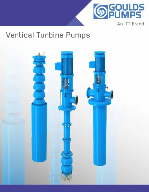
An ITT Brand Vertical Turbine Pumps2Flexibility by Design:Three Pump Models, One Common Bowl Assembly The three different pump models in the vertical turbine line have one thing in common – the hydraulic design of the pump bowl assembly. Using state-of-the-art techniques in turbine pump design, Goulds vertical turbine line covers a wide range of hydraulic conditions to meet virtually every pumping service in the industry with optimum efficiency.Goulds flexibility of design allows the use of a wide range of materials and design features to meet the customrequirements of the user. No matter what the requirements, Goulds can design and manufacture the pump to best satisfy them, specifically and thoroughly.Models VIT, VIC & VISThis bulletin is designed to assist the user in selecting the best pump for the conditions required; however, any questions will be answered promptly by calling the Goulds sales office or representative in your area.Goulds Vertical Turbine Pumps Pump Bowl AssemblyThe bowl assembly is the heart of the vertical turbinepump. The impeller and diffuser type casing are designed to deliver the head and capacity that your system requires in the most efficient way possible. The fact that the vertical turbine pump can be multi-staged allows maximum flexibility both in the initial pump selection and in the event that future system modifications require a change in the pump rating.A variety of material options allows the selection of a pump best suited for even the most severe services. The many bowl assembly options available ensure that the vertical turbine pump satisfies the users’ needs for safe, efficient, reliable and maintenance-free operation. Standard Design Features• Suction Bell - Allows smooth entry of liquid into first stage impeller eye, minimizes foundation opening.• Suction Bell Bearing - Provided for shaft stability. • Sand Collar - Prevents solids from enteringsuction bearing.• Impeller - Semi-open or enclosed forappropriate service.• Pump Shaft - Heavy duty 416SS standard, otheralloys available for strength and corrosion resistance. • Flanged Bowls - Registered fits ensure positivealignment, ease of maintenance.•Diffuser Bowl - Available in variety of cast materials.• Sleeve Type Bearing - Provided at each stage toassure stable operation.• Keyed Impellers - Standard for API applications,18” and larger sizes; furnished on all pumps fortemperatures above 180° F (82° C) and on cryogenicservices. Regardless of size, keyed impellers provideease of maintenance and positive locking underfluctuating load and temperature conditions.Vertical Turbine Pumps3Vertical Turbine Pumps5Flanged ColumnOpen Lineshaft BearingFlanged column / product lubricated lineshaft isrecommended for ease of maintenance. Renewable shaftsleeve or hard facing of shaft available for longer life.Threaded Lineshaft CouplingThreaded lineshaft coupling is commonly used for lowerhorsepower pumps. It is more economical.Enclosed LineshaftThe lineshaft is protected by water flushing the enclosing tube bearing on corrosive / abrasive services. Oil lubricated lineshaft available on long settings.Alignment is attained by register fit between theflange faces.Keyed LineshaftKeyed lineshaft coupling is recommended for motors larger than 700 HP . It provides ease of maintenance.Column sections are provided with flanged ends incorporating registered fits for ease of alignment during assembly to ensure concentricity. Our standard bearing retainers are welded into the column section.6Discharge HeadsDischarge HeadsThe discharge head functions to change the direction of flow from vertical to horizontal and to couple the pump tothe system piping in addition to supporting and aligning the driver. Discharge head accommodates all types of driver configurations. Optional sub-base can be supplied. Goulds offers three basic types for maximum flexibility.VIC DISCHARGE HEADVIC can also be supplied with the pump suction in the can.BELOW GROUND DISCHARGE HEAD Use whenever VIT pump is required to adapt to an underground discharge system.• Finite Element Analysis is typically recommended on thisconfiguration to evaluate the pump’s dynamic behavior and capability to withstand the loads • Robust design as a result of the cantilever load distribution applied to the foundation and anchor bolts• Customized design to minimize the foundation openingVIT DISCHARGE HEADSuitable for all service conditions such as high or low temperature or corrosive services. Various materials available. Segmented elbow available for efficiency improvement. Access ports for easy access to seals andcouplings. Base flange can be machined to match ANSI tankflange.FAN AIR COOLED THRUST POT • Cast steel body meeting API standard• 25,000-hour L10 bearing life • Two or three bearing configurations• Momentary up-thrust capability• Inpro seals - prevent oil contamination• Vibration and temperature monitoring are standard provisions• Oil lubricated thrust bearings & permanently-lubricated radial bearingsVertical Turbine Pumps7Seals & CouplingsAdjustable Coupling (Type A)For vertical solid shaft driver, impeller adjustment made by using adjustable plate in the coupling.Adjustable CouplingAdjustable Spacer Coupling (Type AS)Same function as Type A coupling with addition of spacer. Spacer may be removed for mechanical seal maintenance without removing the driver.Adjustab CouplingPacked Box With or Without Sleeve Open LineshaftWhenever packing lubrication leakage can be tolerated and the discharge pressure does not exceed 150 psi, a packed box may be used. Optional headshaft sleeve or shaft hardfacing available to protect shaft.Water Flush or Oil Lubricated Enclosed LineshaftWater flush tube connection is supplied when pressurized water is introduced into the enclosing tube for bearing protection on abrasive services.Single SealMost popular method — used for low to medium pressures. Cartridge style for ease of installation and maintenance.Dual SealsTwo seals mounted in-line. Chamber between seals can be filled with a buffer liquid and may be fitted with a pressure sensitive annunciating device for safety.Model VITVertical Industrial Turbine Pump Array For higher flows refer to high capacity section• Flows to 70,000 GPM (15,900 m3/Hr)• Heads to 3,500 feet (1,060 m)• Pressures to 2,500 psi (76kg/cm²)• Bowl sizes from 6” to 55” (152.4 mm to 1,400 mm) • Temperatures to 500° F (260° C)• Horsepower to 5,000 HP (3,730 KW)Design Advantages• Fabricated discharge head and flanged column• Flanged bowl construction• 416SS shafting• Alloy construction with external flush of critical wear areas available for corrosive/abrasive services• Built-in alignment and simple piping for less costly installation and ease of maintenance / reduceddowntimeApplications• Cooling Water• Seawater and River Water Intake• Industrial Process Pumps• Utility Circulating Water• Condenser Circulating Water Pumps• Fire Service• Reclaimed Water8Cross Sectional VIT (Product Lube)TYPICAL MARKETS SERVED• Power Generation• Oil & Gas• Mining• Municipal• General Industry • ChemicalMotorMotor Key(Supplied By Motor Vendor)Hub - MotorRing - RetainingPlate - AdjustingHub - PumpPump KeyGland / SplitPackingStuffing BoxHeadshaftHeadCapscrew - Col / HeadColumn - TopCapscrew - Col / ColHex NutColumn - IntermediateLineshaftBearing - LineshaftColumn - BottomCoupling - LineshaftPumpshaftCapscrew - Col / BowlBearing - BowlCapscrew - Bowl / BellBowlSuction BellStrainer (Basket Type)CapscrewMotor / SupportMotor SupportCoupling GuardStud / NutCapscrew Support / HeadGasketBearingBy-Pass Line Assembly(Tube & Fitting)Mounting HolesBy-Pass Return To SumpSoc. HD. CapscrewThrust RingKey - ImpellerImpellerWear Ring - BowlWear Ring - ImpBearing - SuctionPipe PlugVertical Turbine Pumps9Vertical Turbine Pumps10Cross SectionalVIT (Enclosed Lineshaft) TYPICAL MARKETS SERVED• Mining • Oil & Gas • Municipal• Power Generation • General Industry • ChemicalVIT ClosedMotorMotor Key(Supplied By Motor Vendor) Hub - Motor Ring - RetainingSoc HD Capscrew Plate - Adjusting Hex Nut Hub - Pump Pump KeyPipe Plug HeadTube NippleCapscrew Col / HD HeadshaftColumn - TopTube - Encl. Bearing - TubeColumn - Intermediate Capscrew - Col / Col Hex NutLineshaftColumn - Bottom Dish BowlPumpshaftCapscrew - Bowl / Disch Bowl Bearing - ThrottleCapscrew - Bowl / BowlBowlCapscrew - Bowl / Bell Capscrew - Strainer Strainer (Basket Type) Suction BellCapscrew Motor / SupportMotor Support Coupling GuardCapscrew Support / HeadTension PlateOil Lube Water FlushMounting HolesSoc HD CapscrewThrust Ring Key - ImpellerImpellerWear Ring - Bowl Wear Ring - ImpSand Collar Bearing - SuctionPipe PlugModel VIC Vertical Industrial Can-Type Pump Array • Flows to 70,000 GPM (15,900 m3/Hr)• Heads to 3,500 feet (1,060 m)• Pressures to 2,500 psi (76kg/cm²)• Bowl sizes from 6” to 55” (152.4 mm to 1,400 mm)• Temperatures to 500° F (260° C)• Horsepower to 5,000 HP (3,730 KW)Design Advantages• Fabricated discharge head and flanged column• Flanged bowl construction• 416SS shafting• In-Line suction and discharge simplifies installation• Optional suction in can for site piping flexibility• Inherent design features on Model VIC allow efficientoperation at any NPSH available• Alloy construction for corrosive / abrasive servicesApplications• Pipeline Booster• Product Transfer, Refinery Blending• Injection Secondary Recovery• Chemical Transfer• Boiler Feed• Condensate• Cryogenics• LNG Transfer• Light Hydrocarbons• Water ServicesVertical Turbine Pumps11Vertical Turbine Pumps12Cross SectionalVICTYPICAL MARKETS SERVED • Power Generation • Chemical • Mining• General IndustryVIC CommercialCapscrew Motor / SupportMotor Support Coupling GuardGlandSoc HD Capscrew - Gland / Housing Soc HD Capscrew - Housing / HeadCapscrew - Support / HeadO-Ring - Housing / Head Bearing - Seal HousingMounting HolesCapscrew - ImpellerThrust Ring Key - ImpellerImpellerWear Ring - Bowl (Optional) Wear Ring - Imp (Optional)Optional Taper Lock Bearing - SuctionMotorMotor Key(Supplied By Motor Vendor) Hub - Driver Ring - RetainingSoc HD Capscrew / Hex NutSpacerSoc. HD. Capscrew / Hex Nut Plate - Adjusting Key - Pump Hub - PumpO-Ring - Gland / Housing Housing - Seal HeadSeal Flush Plan 13 HeadshaftCapscrew - Head / BarrelO-ringCapscrew - Col / Head Column - TopCapscrew - Col / ColHex NutIntegral Bearing Retainer Column - IntermediateLineshaftOptional Loose RetainerBearing - LineshaftColumn - BottomCoupling - LineshaftPumpshaftCapscrew Col / Bowl Bearing - Bowl Bowl - TopCapscrew - Bowl / BowlBowlCapscrew - Bowl / Bell Suction Bell BarrelVIC CommercialVertical Turbine Pumps13Cross SectionalMotor horsepower margin Motor design required to API 541Motor thrust bearing life at rated conditionMotor thrust bearing life at maximum loadsMotor thrust bearing location Motor to be VSSCoupling will be balanced as assemblySpecial coupling as requiredSocket welded or flanged piping plan required (tubing also available)NDE of nozzle weldsNozzle load 1 x API (standard)For other than steel construction VPO will advise nozzle loadsPost weld heat treatment may be Required on carbon steel fabs Separate sub-base as requiredOne piece shaft as required (as length permits)Corrosion resistant bolting (typical)TESTING NOTES(Per API-610 Latest Edition)If vibration test is required, pump is to be fully tested with job motor.CMTR’s are only required if required by customer.Observed testing is considered witness.Customer is to define inspection requirements.Customer is to define NDE requirements.Hydro testing as required.Performance testing as required.MotorHorizontal alignment Screws as required 1/16” Thread Clearance on 1-1/2”and GreaterAuxiliary sealing required for condensate applicationFigure 25; studs and nuts at sealing housingMechanical seal required Mechanical seal to API 682Additional seal and gland vent tapPressure boundary components stress levelUnless otherwise specified the suction region may be designedfor maximum suction pressure1/8” Corrosion allowanceIf specified can mounting flange may be requiredBearing spacing as requiredWelded retainersKeyed impellers (standard)Impeller dynamically balanced to 8W/NBowl wear ring requiredSet screw or tack weld wear rings Different hardness required (by material)VIT (Per API-610)TYPICAL MARKETS SERVED • Oil & Gas • Chemicals• Pipeline Transfer • MiningModel VISVertical Industrial Turbine Pump Array • Flows to 70,000 GPM (15,900 m3/Hr)• Heads to 3,500 feet (1,060 m)• Pressures to 2500 psi (76kg/cm²)• Bowl sizes from 6” to 55” (152.4 mm to 1,400 mm)Design Advantages• Ideal for deep set applications where use of lineshaft pumps is impractical• Complete unit is installed underground, resulting in quiet operation and space saving• Long life / low maintenance − no lubrication,alignmentApplications• Irrigation• Service Water• Deep Well• Sea Water Lift14Vertical Turbine Pumps15Cross SectionalVISTYPICAL MARKETS SERVED • General Industry • Oil & GasVISDischargeSuctionDischarge Adapter Bearing - Suction AdapterSand Collar BowlBearing - Bowl Optional Taper Lock Impeller Wear Ring - BowlPumpshaft Screen SuctionBearing - Suction Adapter Coupling Suction AdapterOptional ShroudSubmersible MotorHydraulic Coverage16Vertical Turbine Pumps17High Capacity PumpsModel WC-GPDESIGN FEATURES FOR OPTIMUM EFFICIENCY , RELIABILITY AND COST SAVINGS• Hydraulic selection at best efficiency point usingadvanced 3-D tools with parametric design. Each pump is designed for optimum hydraulic and mechanicalconditions for the required application. The suction bell provides flared inlet controls to accelerate the fluid to the desired inlet velocity. Outer wall on the bowls provides structural integrity and the flanges with precise rabbet fits are located at each end for positive alignment. The contour of the diffuser/bowl provides accurate fit to the impeller for optimum operating efficiency.• Cantilever rotor design with no tail bearings. Extra long length bearing or double bearing for added stability in the upper bearing above the first stage impeller. No auxiliary lubrication system needed. The process fluid ensures proper lubrication at all times for increased life expectancy. Elimination of the tail bearing provides lower NPSHR values and improved fluid inlet conditions for hydraulic performance.• Computational fluid dynamic analysis is available todetermine the sump flow conditions at the pump inlet for superior performance.• Using a thermal casting solidification simulation program, Goulds Pumps is able to design optimum castings to meet specific customer conditions, providing better design standards in the market. • Shaft sleeves optional. Provides renewable bushings.Prevents wear of shaft itself. Materials can be providedto resist abrasion which are not available in shafting insome cases. Recommended on large shafts due to the shaft replacement cost and lead times.• Pull-out design is optional. This option provides an effective way to maintain the equipment and replace wear components without the need to remove the complete pump and disconnect the flanges from the main pipe. The removable component is only the rotor for optimum reliability and to reduce costs during maintenance.18High Capacity PumpsModel WC-GPDESIGN FEATURES FOR OPTIMUM EFFICIENCY , RELIABILITY AND COST SAVINGS• Innovative O-Head design using finite element analysis provides maximum equipment reliability throughout its operating hydraulic range without high vibrations from structural resonance frequency. In addition, lateral and torsional rotor analysis addresses unstable rotor dynamics.• Thrust pot design is optional. It is designed to carry the pump down thrust generated by the rotor weight and the hydraulic action of the pump during operation. Thrust pots are ideally on units equipped with IEC motors where their thrust capacity is basically zerobeyond the motor weight. Thrust pots are designed for easy dismantling without the need to remove the unit driver. Additional advantages include capacity of the thrust pot to withstand a large range of thrust forces, meeting international standards for bearingtemperature and extended life, in addition to being aircooled for most of the applications.• The hydraulic balance achieved on the rotor does not have balance holes in the impeller like other brands on the market. Reducing the down thrust of the pump will reduce the cost of the driver by reducing the size of the thrust bearing in the motor, which makes the Goulds Pumps design more competitive.• Below-grade discharge elbow is optional, and the structural analysis design considers the overturning forces with respect to the anchor bolt location and pump centerline. This results in robust components to prevent equipment deformation. Discharge heads are designed to withhold certain discharge hydraulic and mechanical forces. It is always recommended to minimize these external forces by supporting the system independently. Do not use the rotating equipment as a piping anchor.Vertical Turbine Pumps19High Capacity & Higher Head PumpsModel WC-GPVertical circulating water pumps or wet pit columnpumps are classified as VS1 pumps for power generation condenser cooling, recirculation and desalination sea water intake, and as VS3 pumps for flood protection, storm water disposal, waste treatment plants, industrial services, and sump drainage.High capacity pumps having a CCW (counter clockwise) rotation when viewing the equipment from the top meet Hydraulic Industry Standards and are in full compliance. These high capacity pumps can be designed in multistage with a HEAVY DUTY configuration for a wide range of heads and extended service life, and are ideal when the installation requires minimum floor space.Pumps ship completely assembled to the job site as long as they fit within freight dimension limitations. Pumps are shipped in sub-assemblies when the complete assembly exceeds the capacity of the transportation.T D H - M e t e r sCapacity in 1,000 cubic Meters Per Hour105017345180100200Capacity in 1,000 U.S. GPM3005T D H - M e t e r sCapacity in 1,000 cubic Meters Per Hour1661371077646。
高 质 泵安装、操作和维修手册Goulds PumpsITT IndustriesVIS 型第1章——简介1-1 简介1-2Goulds泵巧妙结构设计、合理选材确保了泵的长期、无故障运行。
正确的安装使用、周期性检测、状态监测、精心维护将延长泵的使用期和良好的运行。
本手册可帮助操作人员理清泵的结构,掌握泵的正确安装、操作和维修方法。
1-3 通读第1至第6章,将手册放在手头以便查阅。
更详细的资料请与加利弗尼亚工业城高质泵公司立式泵部或您当地的办事处联系索取。
警告高质泵公司不承担由于未遵循手册中的说明而造成的设备损坏或误工。
1-4 接收和检查1-5 泵在从载运工具上卸下来前应小心支撑。
小心搬运各个件。
在对泵拆箱前要先检查货运箱是否有损坏。
拆箱后,对泵进行目视检查并检查如下各项:A. 泵装配的内容是否与装箱单一致。
B. 所有的零部件是否有损坏。
1-6 若有任何缺失或损坏应立即通知运抵货物的当地承运公司,并在运单上正确注释。
这样可以避免索赔时发生争议,并便于给予快速、满意的调节。
1-7 所需材料和设备1-8 由于泵的尺寸和安装形式的不同,所需的材料和设备是不一样的。
因此下述讨论及标准工具、用品仅作参考。
A. 大型材料木磨擦块或钢钳用于扬水管起吊的规定型号和正确尺寸的钢管吊车。
约10米长,对于作业载荷尺寸足够的缆索。
B. 手持工具管钳子两个链条钳机械手持工具C. 仪表一个兆欧表,或者能测量电阻的类似仪表。
钳形电流表伏特计D. 安装设备虽然有时也使用移动式起重机,但推荐使用正确设计的泵安装架。
滑轮必须安装到可以使吊钩提升到高于最长件三米处的地方。
起吊装置必须具有足够的强度和钢度,能够安全承载设备总重。
小心记住—无论什么型式的起重设备,也无论什么型号的泵机设备,首要一点都是:安全第一。
第2章——贮存2-1 贮存2-2 Goulds公司对其产品在运输中进行了认真的保存和保护。
但根据设备贮存环境的恶劣程度不同,出厂时涂的防护层的有效期为3个月至18个月不等。
Goulds Pumps 安装、操作和使用手册IC系列1、概述1.1前言必须确保所有涉及安装、运行、检查和维修的员工熟悉有关防止事故的规定并能胜任该项工作。
应对没有相关知识的员工提供指导培训。
泵或机组(即泵加电机)的安全只有在遵守附录资料表中给定的参数和第4章“安装和运行”进行操作的前提下由生产厂商负责。
操作者需按本操作手册下面提到的指导和安全要求进行操作。
只有遵守机械工程和电气工程领域中的规定,并严格按照维护和安装步骤,泵或机组才能平稳运行。
如果本操作手册内容不能满足要求,请与本公司联系。
如果不遵守本操作手册,制造商将不对泵或机组负责。
本手册应放在安全的地方以便将来查询。
如果泵或机组被转移到其它地方,操作手册、运行工况及最终合同中规定的限制条件都必须能满足。
本操作手册并没有全面考虑到所有的设计细节和变型,以及在安装、运行和维护中可能出现的变化。
机械方面的替换和改变需获得制造商的同意,应尽量使用原厂备件或制造商提供的附件以保证安全,本公司不承担因使用其它零件而造成的后果。
本操作手册版权属于本公司,该手册只能由业主拥有。
操作手册中所含的技术内容和图纸,不论是整体或部分,都不得复印、发放或任何未经授权的,以竞争为目的的使用。
1.2质量保证质量保证责任按供货条件和合同确认条款。
质保期内的维修工作一般只有本公司负责或经本公司授权执行,否则将不承担质保责任。
更长期的质保内容只包括特定材料的正确使用和装卸。
自然的磨损和裂纹及所有零件的工作磨损,如叶轮、轴封、轴、轴套、轴承、耐磨环等,或由运输和不正确的装卸引起的损坏,不属于本质保范围。
为确保质保条款能得到实施,泵在使用中必须遵守铭牌、合同条款以及数据表中给定的运行工况。
正确的操作对材料的磨损以及泵和轴封的平稳运行都很重要。
如果实际运行工况有某一方面或多方面的变化,应咨询本公司书面确认泵能否使用。
1.3安全规程本手册包含了泵在安装、试运行及运行期和维修期内必须执行的、重要的指导内容。
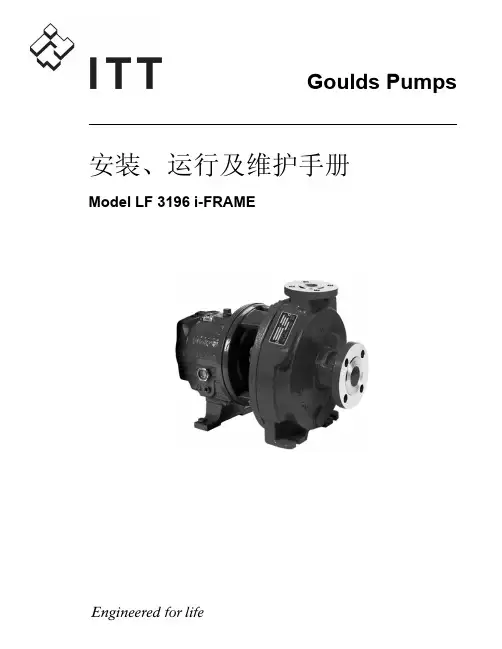
Installation, Operation, andMaintenance ManualModel e-HMTable of Contents Table of Contents1 Introduction and Safety (2)1.1 Introduction (2)1.2 Inexperienced users (2)1.3 Safety terminology and symbols (2)1.4 Warranty (2)1.5 Spare parts (2)1.6 Declaration of Conformity (2)2 Transportation and Storage (2)2.1 Inspect the delivery (2)2.2 Transportation guidelines (3)2.3 Storage guidelines (3)3 Product Description (3)3.1 Pump design (3)3.2 Application limits (3)3.3 The data plate (3)4 Installation (3)4.1 Facility requirements (4)4.1.1 Pump location (4)4.1.2 Piping requirements (4)4.2 Electrical requirements (4)4.3 Install the pump (5)4.3.1 Install the pump on a concrete foundation (5)4.3.2 Electrical installation (5)5 Commissioning, Startup, Operation, and Shutdown (5)5.1 Prime the pump (5)5.2 Check the rotation direction (three-phase motor) (5)5.3 Start the pump (6)6 Maintenance (6)6.1 Service (6)7 Troubleshooting (6)7.1 Troubleshooting table (6)1 Introduction and Safety1.1 IntroductionPurpose of this manualThe purpose of this manual is to provide necessary information for:•Installation •Operation •MaintenanceCAUTION:Read this manual carefully before installing and using the product. Improper use of the product can cause personal in-jury and damage to property, and may void the warranty.NOTICE:Save this manual for future reference, and keep it readily available at the location of the unit.1.2 Inexperienced usersWARNING:This product is intended to be operated by qualified person-nel only.Be aware of the following precautions:•Persons with diminished capacities should not operate the prod-uct unless they are supervised or have been properly trained by a professional.•Children must be supervised to ensure that they do not play on or around the product.1.3 Safety terminology and symbolsHazard levelsHazard categoriesHazard categories can either fall under hazard levels or let specific sym-bols replace the ordinary hazard level symbols.Electrical hazards are indicated by the following specific symbol:Electrical Hazard:Hot surface hazardHot surface hazards are indicated by a specific symbol that replaces the typical hazard level symbols:CAUTION:Description of user and installer symbols1.4 WarrantyFor information about warranty, see the sales contract.1.5 Spare partsWARNING:Only use original spare parts to replace any worn or faulty components. The use of unsuitable spare parts may cause malfunctions, damage, and injuries as well as void the guar-antee.For more information about the product's spare parts, refer to the Sales and Service department.1.6 Declaration of ConformityWe at,Xylem Inc./Goulds Water Technology 1 Goulds Drive Auburn, NY 13021Declare that the following products: NPE, MCS, MCC, 3642/3752,3656, 3656 SP, GB, e-SV, SVI, NPO, Prime Line SP, HB, e-HM, HMS, LC,NPV, LB, LBS comply with Machine Directive 06/42/EC. This equipment is intended to be incorporated with machinery covered by this direc-tive, but must not be put into service until the machinery into which it is to be incorporated has been declared in conformity with the actual provisions of the directive.Nick DaddabboIndustrial Product Engineer2 Transportation and Storage2.1 Inspect the delivery1.Check the outside of the package.2.Notify our distributor within eight days of the delivery date, if the product bears visible signs of damage.3.Remove the staples and open the carton.4.Remove the securing screws or the straps from the wooden base (if any).5.Remove packing materials from the product. Dispose of all pack-ing materials in accordance with local regulations.6.Inspect the product to determine if any parts have been damaged or are missing.7.Contact the seller if anything is out of order.1 Introduction and Safety2.2 Transportation guidelinesPrecautionsWARNING:•Observe accident prevention regulations in force.•Crush hazard. The unit and the components can be heavy. Use proper lifting methods and wear steel-toed shoes at all times.Check the gross weight that is indicated on the package in order to se-lect proper lifting equipment.Position and fasteningThe unit can be transported either horizontally or vertically. Make sure that the unit is securely fastened during transportation, and cannot roll or fall over.2.3 Storage guidelinesStorage locationNOTICE:•Protect the product against humidity, dirt, heat sources, and me-chanical damage.•The product must be stored at an ambient temperature from -40°C to +60°C (-40°F to 140°F).3 Product Description3.1 Pump designThe pump is a multistage, non-self priming pump. The pump can be used to pump:•Cold water •Warm water Intended useThe pump is suitable for:•Civil and industrial water distribution systems•Irrigation (for example, agriculture and sporting facilities)Improper useDANGER:Do not use this pump to handle flammable and/or explosive liquids.WARNING:Improper use of the pump may create dangerous conditions and cause personal injury and damage to property.NOTICE:Do not use this pump to handle liquids containing abrasive, solid, or fibrous substances, toxic or corrosive liquids, potable liquids other than water, or liquids not compatible with the pump construction material.An improper use of the product leads to the loss of the warranty.3.2 Application limitsTable 1: Pressure and temperature limitsSeal Code 1HM, 3HM5HM10HM,15HM,22HM2-6 Stages 7+ Stages 2-5 Stages 6+ Stages All StagesBQE 147PSI at 248F 235PSI at 248F 147PSI at 248F 235PSI at 248F 235PSI at 248F BQV 147PSI at 248F 235PSI at 248F 147PSI at 248F 235PSI at 248F 235PSI at 248F QQE 147PSI at 248F 235PSI at 194F 147PSI at 248F 235PSI at 194F 235PSI at 194F QQV 147PSI at 248F 235PSI at 194F147PSI at 248F235PSI at 194F235PSI at 194FBVE147PSI at 194FNot Avail-able 147PSI at 194F Not Avail-able Not Avail-able3.3 The data plateThe data plate is a label on the pump. The data plate lists key productspecifications.1.Goulds Water Technology Catalog Number2.Capacity range3.TDH range4.Rated speed5.Rated horsepower6.Maximum operating pressure7.Maximum fluid temperature8.Pump serial numberIMQ or other marks (for electric pump only)Unless otherwise specified, for products with a mark of electrical-relat-ed safety approval, the approval refers exclusively to the electrical pump.3 Product Description4 InstallationPrecautionsWARNING:•Observe accident prevention regulations in force.•Use suitable equipment and protection.•Always refer to the local and/or national regulations,legislation, and codes in force regarding the selection of the installation site, plumbing, and power connections.4.1 Facility requirements4.1.1 Pump locationDANGER:Do not use this unit in environments that may contain flam-mable/explosive or chemically aggressive gases or powders.GuidelinesObserve the following guidelines regarding the location of the prod-uct:•Make sure that no obstructions hinder the normal flow of the cool-ing air that is delivered by the motor fan.•Make sure that the installation area is protected from any fluid leaks, or flooding.•If possible, place the pump slightly higher than the floor level.•The ambient temperature must be between -30°C (-22°F) and +40°C (+104°F) unless otherwise specified in the data plate.•The relative humidity of the ambient air must be less than 50% at +40°C (+104°F).Installation above liquid source (suction lift)The theoretical maximum suction height of any pump is 34 ft. In prac-tice, this is not achieved due to the following conditions affecting the suction capability of the pump:•Temperature of the liquid•Elevation above the sea level (in an open system)•System pressure (in a closed system)•Resistance of the pipes•Own intrinsic flow resistance of the pump •Height differences NOTICE:Do not exceed the pumps suction capacity as this could cause cavita-tion and damage the pump.4.1.2 Piping requirementsPrecautionsWARNING:•Use pipes suited to the maximum working pressure of the pump. Failure to do so can cause the system to rup-ture, with the risk of injury.•Make sure that all connections are performed by quali-fied installation technicians and in compliance with the regulations in force.•Do not use the on-off valve on the discharge side in the closed position for more than a few seconds. If the pump must operate with the discharge side closed for more than a few seconds, a bypass circuit must be instal-led to prevent overheating of the water inside the pump.Piping checklist•Pipes and valves must be correctly sized.•Pipe work must not transmit any load or torque to pumpflanges.4.2 Electrical requirements•The local regulations in force overrule these specified require-ments. In the case of fire fighting systems (hydrants and/or sprin-klers), check the local regulations.Electrical connection checklistCheck that the following requirements are met:•The electrical leads are protected from high temperature, vibra-tions, and collisions.•The power supply line is provided with:•A short-circuit protection device •A main disconnect switch.The electrical control panel checklistNOTICE:The control panel must match the ratings of the electric pump. Improp-er combinations could fail to guarantee the protection of the motor.Check that the following requirements are met:•The control panel must protect the motor against overload and short-circuit.•Install the correct overload protection (thermal relay or motor pro-tector).Pump TypeProtectionSingle phase standard electric pump up to 3 HP•Built-in automatic reset thermal-overload protec-tion•Short circuit protection (must be supplied by the installer)Three-phase electric pump•Thermal protection (must be supplied by the instal-ler)•Short circuit protection (must be supplied by the installer)•The control panel must be equipped with a dry-running protec-tion system to which a pressure switch, float switch, sensors, or other suitable device is connected.•The following devices are recommended for use on the suction side of the pump:•When the liquid is pumped from a water system, use a pres-sure switch.•When the liquid is pumped from a storage tank or reservoir,use a float switch or sensors.•When thermal relays are used, relays that are sensitive to phase failure are recommended.The motor checklistUse cable according to rules with 3 leads (2+earth/ground) for single phase versions and with 4 leads (3+earth/ground) for three-phase ver-sion.4 Installation4.3 Install the pump4.3.1 Install the pump on a concrete foundation1.Piping support2.On-off valve3.Flexible pipe or joint4.Check valve5.Control panel6.Do not install elbows close to the pump7.Bypass circuit8.Eccentric reducere wide bends 10.Positive gradient11.Piping with equal or greater diameter than the suction port e foot valve13.Do not exceed maximum height difference 14.Ensure adequate submersion depth1.Anchor the pump onto the concrete or equivalent metal structure.•If the liquid temperature exceeds 50°C, the unit must be anchored only by the motor bracket side and not also by the side of the inlet supporting bracket•If the transmission of vibrations can be disturbing, then pro-vide vibration-damping supports between the pump and the foundation.2.Remove the plugs covering the ports.3.Assemble the pipe to the pump threaded connections.Do not force the piping into place.4.3.2 Electrical installationPrecautionsElectrical Hazard:•Make sure that all connections are performed by quali-fied installation technicians and in compliance with the regulations in force.•Before starting work on the unit, make sure that the unit and the control panel are isolated from the power sup-ply and cannot be energized.Grounding (earthing)Electrical Hazard:•Always connect the external protection conductor to ground (earth) terminal before making other electrical connections.Connect the cable1.Connect and fasten the power cables according to the wiring dia-gram under the terminal box cover.a)Connect the ground (earth) lead.Make sure that the ground (earth) lead is longer than the phase leads.b)Connect the phase leads.NOTICE:Tighten the cable glands carefully to ensure the protection against the cable slipping and humidity entering the terminal box.2.If the motor is not equipped with automatic reset thermal protec-tion, then adjust the overload protection according to the nominal current value of electric pump (data plate).5 Commissioning, Startup,Operation, and ShutdownPrecautionsWARNING:Make sure that the drained liquid does not cause damage or injuries.NOTICE:•Never operate the pump below the minimum rated flow.•Never operate the pump with the delivery ON-OFF valve closed for longer than a few seconds.•Do not expose an idle pump to freezing conditions. Drain all liq-uid that is inside the pump. Failure to do so can cause liquid to freeze and damage the pump.•The sum of the pressure on the suction side (water mains, gravity tank) and the maximum pressure that is delivered by the pump must not exceed the maximum working pressure that is allowed (nominal pressure PN) for the pump.•Do not use the pump if cavitation occurs. Cavitation can damage the internal components.5.1 Prime the pumpH>0H<0+H-H121231.Fill plug2.Drain plug3.FunnelInstallations with liquid level above the pump (suction head)Close the on-off valve located downstream from the pump.Installations with liquid level below the pump (suction lift)Open the on-off valve that is located upstream from the pump and close the on-off valve downstream.5.2 Check the rotation direction (three-phase motor)Follow this procedure before start-up.1.Start the motor.2.Stop the motor.3.If the rotation direction is incorrect, then do as follows:a)Disconnect the power supply.b)In the terminal board of the motor or in the electric controlpanel, exchange the position of two of the three wires of the supply cable.c)Check the direction of rotation again.5 Commissioning, Startup, Operation, and Shutdown5.3 Start the pump1.Start the motor.2.Gradually open the on-off valve on the discharge side of the pump.At the expected operating conditions, the pump must run smoothly and quietly. If not, refer to Troubleshooting (page 6).3.If the pump does not start in correctly in 30 seconds, then do the following:a)Switch off the pump.b)Reprime the pump.c)Start the pump again.4.Switch off and on the pump (for about 30 seconds of continuos running) and make sure that all the trapped air is bled out by re-peating this 2–3 times.NOTICE:Make sure that the pump has bled away all the trapped air. Failure to do so can harm the product.6 MaintenancePrecautionsElectrical Hazard:Disconnect and lock out electrical power before installing orservicing the unit.WARNING:•Maintenance and service must be performed by skilled and qualified personnel only.•Observe accident prevention regulations in force.•Use suitable equipment and protection.6.1 ServiceThe pump does not require any scheduled routine maintenance. If the user wishes to schedule regular maintenance deadlines, they are de-pendent on the type of pumped liquid and on the operating conditions of the pump.Contact the local sales and service representative for any requests or information regarding routine maintenance or service.7 TroubleshootingIntroductionAlways specify the exact pump type and identification code when re-questing information or spare parts from the Sales and Service depart-ment.For other situation not mentioned in the table, refer to the Sales and Service department.7.1 Troubleshooting tableProblem Cause and solutionThe pump does not start.•The thermo-overload protection in the single-phase motor has tripped; it will automatically reset when the motor cools down.•Check the power supply wiring to see that the connections are all tight•Check to see that the circuit breaker or ground-fault protection device has tripped. Or replace any fuses that may have blown.•Check to see if any protection device installed for dry running protection has tripped or hung up.Problem Cause and solutionThe pump starts up but the ther-mal protector is triggered after a short time or the fuses blow.•The power supply cable is damaged, the motor short circuits or thermal protector or fuses are not suited for the motor current. Check and re-place the components as necessary.•The thermo-overload protection (single phase)or of the protection device (three-phase) trips due to excessive current input. Check the pump working conditions.•A phase in the power supply is missing. Check the power supply.•The pump is clogged with solids and the impel-ler becomes bound. Clean the pump.The pump starts but does not de-liver any liquid.•Air is entering the suction piping, check the liq-uid level, the tightness of the suction pipes and the operation of the foot valve.•The pump is not correctly primed. Repeat the instructions in Prime the pump (page 5).The pump’s de-livery is re-duced.•Check for restrictions in the piping system.•Wrong rotation of the impeller (three-phase).Check the direction of rotation.•The pump is not correctly primed. Repeat the instructions in Prime the pump (page 5).6 MaintenanceXylem |’zīləm|1) The tissue in plants that brings water upward from the roots2) A leading global water technology companyWe're 12,000 people unified in a common purpose: creating innovative solutions to meet our world's water needs. Developing new technologies that will improve the way water is used, conserved, and re-used in the future is central to our work. We move, treat, analyze, and return water to the environment, and we help people use water efficiently, in their homes, buildings, factories and farms. In more than 150 countries, we have strong, long-standing relationships with customers who know us for our powerful combination of leading product brands and applications expertise, backed by a legacy of innovation.For more information on how Xylem can help you, go to Xylem Inc.2881 East Bayard Street, Suite A Seneca Falls, NY 13148USATel: (866) 325-4210Fax: (888) 322-5877Visit our Web site for the latest version of this document and more informationThe original instruction is in English. All non-English instructions are translations of the original instruction.© 2013 Xylem IncGoulds is a registered trademark of Goulds Pumps, Inc. and is used under license.。
Operating Instructions and Parts Manual INSTALLATION (CONTINUED)Leaking joints or couplings will allow air to leak into the pipe and cause abnormal pump operation. Make sure to use pipe joint compound on all male pipe threads.DUG WELL, CISTERN, LAKE AND SPRING INSTALLATION (FIGURE 16, ON PAGE 10)• Install a foot valve on inlet pipe and lower into water.The foot valve should be at least 18 in. from thebottom of the well or sand or sediment could bedrawn into the system.NOTE: When a lake is used as a water supply, make sure the inlet pipeis deep enough to be submerged at all times.Slope the horizontal piping upward toward the pump to prevent trappingair. The pipe must be removed during winter months or protected againstfreezing.Protect the pipe from damage from swimmers and boats.Install a screen around the inlet pipe to preventthe entrapment of swimmers.DEEP WELL INSTALLATIONDRILLED WELL (4 IN. OR LARGER) WITH TWO PIPE JET (FIGURES 16,ON PAGE 10 AND 3, ON PAGE 4)1. Assemble a 1-1/4 in. foot valve (not included) to the jet body. A 1-1/4in. coupling is required to connect the larger pipe to the jet assembly.2. Connect the 1 in. pipe threads into the smaller opening in the jetbody.3. Lower the jet into the well. Add pipe as needed. Be sure to use pipejoint compound, or plumber’s seal tape on all male threads.4. Position the jet 10 - 20 feet below the lowest anticipated water level,but never closer than 5 feet from the bottom of the well, if possible.5. Install a well seal to support the pipe and prevent surface water andother contaminants from entering the well.6. Install the horizontal pipe from the well to the pump. Piping from thevertical well pipe to the pump should never be smaller than the wellpipes.7. Slope both pipes upward toward the pump to prevent trappingair. If the horizontal distance exceeds 25 feet, see Chart 1 for therecommended pipe sizes.DUG WELL, CISTERN, LAKE AND SPRING WITH TWO PIPE JET(FIGURE 16, ON PAGE 10)1. Install a 1-1/4 in. foot valve (not included) to the jet body. A 1-1/4 in.coupling is required to connect the larger pipe to the jet assembly.2. Connect the 1 in. pipe threads into the smaller opening in the jetbody.3. Lower the jet into the water below the lowest anticipated water level,but never closer than 18 in. from the bottom. Sand or debris may bedrawn into the system if the jet is too close to the bottom.4. Provide protection for the jet and pipes against damage from boatsor swimmers if a lake is used for the water supply.Install a screen around the inlet pipe to preventthe entrapment of swimmers.5. Slope the horizontal pipes upward toward the pump to preventtrapping air. If horizontal distance exceeds 25 feet, see Chart 1 forrecommended pipe sizes.DRILLED WELL (2 IN.) WITH SINGLE PIPE PACKER (FIGURES 16 AND4)NOTE: Single pipe packer jets rely on the space between single pipe andinside of well casing for return water to operate jet. T wo inch installationsmust use 1-1/4 in. galvanized steel pipe with special turned couplings (1-13/16 in. O.D.) to avoid restricting flow of return water back to jet.1. Assemble the foot valve and packer to the jet body.2. Lubricate the rubber cups with petroleum jelly.3. Attach the first section of pipe and lower jet into well.4. Add pipe until the jet is positioned 5 - 15 feet below the lowestanticipated water level. The jet should never be closer than 5 feetfrom the bottom of the well or sand and sediment may be drawninto the system.5. With the jet in position, fill the pipes with water to make sure therubber cups are sealed against inside of the well casing. It may benecessary to move the jet up and down to seat the cups.6. Install the casing adapter and the horizontal pipes.7. Slope both pipes upward toward the pump to eliminate trappingair. If the horizontal distance exceeds 25 feet, see Chart 1 for therecommended pipe sizes.1-1/4 IN. PIPEFigure 4 - Single Pipe JetPACKERFOOT VALVECUPSCWS SeriesDeep WellInlet: Suction 1-1/4 in.1-1/2 in.Inlet: Drive 1 in.1-1/4 in.Outlet3/4 in.1 in.DEEP WELL PUMP WITH HORIZONTAL AND VERTICAL STORAGE TANK (FIGURES 5 AND 6)1. Install the air volume control on the tank as shown.2. Connect the copper tube from the air volume control to the 1/8 in.NPT opening directly above the 1-1/4 in. opening on the front of the pump.3. Install a valve and isolating hose between the system and the houseplumbing to aid in pump removal for servicing and for reducing noise transmitted through the house piping.4. Provide a hose bib (faucet) at the lowest point in the system to drainfor service or storage.DEEP WELL PUMP WITH PRE-CHARGED STORAGE TANK (FIGURE 7)1. Check tank pre-charge using a tire pressure gauge. Set air pressurein tank to 28 psi which is 2 psi below pressure switch cut-in level. An air valve is located on the side and will accept a standard fitting from a bicycle pump or air line.2. Check the pressure with the power off, faucets open and no waterflowing (zero water pressure).3. Install a valve and isolator hose between the system and the houseplumbing to aid in pump removal for servicing and for reducing noise transmitted to the house through the piping.4. Provide a hose bib (faucet) at the lowest point in the system to drainfor service or storage.AIR VOLUME CONTROL TUBINGSUCTION。
INSTRUCTION MANUALIM042TABLE OF CONTENTSSUBJECT PAGE Safety Instructions (3)Descriptions and Specifications (3)Piping (3)Slide Rail Installation (3)Operation (6)W orking Load Limits (6)W arnings (6)Limited W arranty (8)Owner’s InformationPump Model Number:Pump Serial Number:Control Model Number:Dealer:Dealer Phone No.Date of Purchase: Installation:23SAFETY INSTRUCTIONSTO AVOID SERIOUS OR FATAL PERSONALINJURY OR MAJOR PROPERTY DAMAGE, READ AND FOLLOW ALL SAFETY INSTRUCTIONS IN MANUAL AND ON PUMP .THIS MANUAL IS INTENDED TO ASSIST IN THE INSTALLATION AND OPERATION OF THIS UNIT AND MUST BE KEPT WITH THE SLIDE RAIL.This is a SAFETY ALERT SYMBOL . When you see this symbol on the pump or in the manual, look for one of the fol-lowing signal words and be alert to the potential for personal injury or property damage.W arns of hazards that WILL causeserious personal injury, death or major property damage.W arns of hazards that CAN causeserious personal injury, death or major property damage.W arns of hazards that CAN cause per-sonal injury or property damage.NOTICE: INDICATES SPECIAL INSTRUCTIONSWHICH ARE VERY IMPORTANT AND MUST BE FOLLOWED.HAZARDOUS LIQUIDS ORFLAMMABLE GASES CAN CAUSE FIRE, BURNS OR DEATH.THOROUGHLY REVIEW ALLINSTRUCTIONS AND WARNINGS PRIOR TO PERFORMING ANY WORK ON THIS UNIT.MAINTAIN ALL SAFETY DECALS.NOTICE: INSPECT UNIT FOR DAMAGE ANDREPORT ALL DAMAGE TO THECARRIER OR DEALER IMMEDIATELY .DESCRIPTIONS AND SPECIFICATIONSGoulds Pumps A10 slide rail systems provide easy wet well pump removal, utilize a self-cleaning quick discon-nect and guide assembly, and eliminate the need to enter the wet well.ModelSlide Rail Discharge Pump Discharge A10-12 1¼” NPTM 1¼” F A10-2015 1½” NPTM 1½” F A10-20 2” NPTM 2” FA10-30 and 4” 125# 3” ANSI Flange A10-40 ANSI Flange 4” ANSI Flange A10-60 6” 125# 4” ANSI FlangeANSI FlangePIPINGSystem piping MUST conform to all local and national plumbing codes and practices.T o maximize the discharge flow, discharge piping should be at least as large as the pump discharge. Keep thedischarge pipe as short as possible and avoid unnecessary fittings.SLIDE RAIL INSTALLATIONFAILURE TO DISCONNECT ANDLOCKOUT ELECTRICAL POWER BEFORE ATTEMPTING ANY MAINTENANCE CAN CAUSE SHOCK, BURNS OR DEATH.NOTICE: ALL DIMENSIONS ARE IN INCHES. DONOT USE DIMENSIONAL DATA FOR CONSTRUCTION PURPOSES.Installation of the slide rail system should locate the pump opposite the influent opening, preventing stagnate areas where solids can settle.NOTICE: GUIDE RAILS MUST BE PLUMB TOFACILITATE PUMP(S) INSTALLATION OR REMOVAL.The containment area floor MUST be flat under the slide rail base and have sufficient loading capacity to support the entire weight of the assembly , including the slide rail base, slide rail guide, pump and all assorted piping.Prior to anchoring the slide rail base to the containment area floor, ensure adequate clearance for pump(s) instal-lation or removal AND for access doors.NOTICE: MATERIAL SELECTION FORCONTAINMENT AREA EQUIPMENT MUST BE COMPATIBLE WITHANTICIPATED FLUIDS AND SERVICE.Slide Rail Systems – A10-12, A10-20, A10-2015T ypical hardware specifications, piping arrangements and basin attachment dimensions are provided in Figure 1 and T able 1.A10-12, A10-20, A10-2015Figure 1Table 1: Guide Rail Base DimensionsSIZE A" B" C" A10-12 3 4½ 10 A10-20 3¾ 5½ 12 A10-2015 3¾ 5½ 121/2”45Slide Rail Systems – A10-30 and A10-40The A10-30 system is designed for pumps with a 3", 125# ANSI flanged discharge. The A10-40 system is designed for pumps with a 4", 125# ANSI flanged discharge. Both 3" and 4" flanged pumps bolt directly to their respective slide rail cast iron pump adapters. The adapter, which slides up and down on the rails, mates with the slide rail base and the integrally cast elbow to provide a 4", 125# ANSI flanged discharge connec-tion. See Figure 2 and T able 2 for the typical hardware specifications, piping arrangements and basin attachment dimensions.24 - 7Slide Rail Systems – A10-60The A10-60 system is designed for pumps with a 4", 125# ANSI flanged discharge. The pump bolts directly to the slide rail cast iron pump adapter, mating with the slide rail base and integrally cast elbow to provide a 6", 125# ANSI flanged discharge connection. See Figure 2 and T able 2 for the typical hardware specifications, pip-ing arrangements and basin attachment dimensions.A10-30, A10-40 and A10-60Figure 2Table 2 SIZE A" BC" D" E" F"A10-30 7¼ 4" ANSI 125# Flange 12 7 13 1 A10-40 75/18 4" ANSI 125# Flange 12 7 13 1 A10-6085/166" ANSI 125# Flange17101526WORKING LOAD LIMITCable A10-12, A10-20 and A10-2015The working load limit is based on a load being uniform-ly applied in a straight line pull.3/16" 7x19 304SS Air Craft Cable WLL = 740 lbs.Do not exceed safe working load limits.WARNINGSInspectionWire ropes, cables and attachments must all be inspected regularly for visible damage or distortion, elongation, corrosion, cracks, nicks or abrasion which may cause failure or reduce the original strength or ability of the products to perform safely. User must determine whether future use of the wire rope or cable would constitute a safety hazard to life or property.SafetyRefer to WARNING and CAUTION labels prior to use.Keep out from under any raised loads and keep out of the line of force of any load.Do not use wire ropes or cables for any purpose other than which it was intended.AVOID SHOCK LOADSWarningsFailure to use wire ropes or cables properly may cause loads to slip or fall.Failure to read, understand and follow these instructions may cause death or serious injury.Do not exceed safe working load limits.OPERATIONDO NOT LIFT, CARRY OR HANGPUMP BY THE ELECTRICAL CABLE. DAMAGE TO THE ELECTRICAL CABLE CAN CAUSE SHOCK, BURNS OR DEATH.Raise and lower the pump in the containment area using the lifting cable attached to the system's quick disconnect for the A10-12, A10-2015 or A10-20, and to the pump's lifting eye/strap for the A10-30, A10-40 and A10-60. DO NOT use electrical cable and DO NOT damage the elec-trical cables while raising and lowering unit. A10-40 and A10-60 units can be used in conjunction with a lifting bail (part # ABAIL2).T o ensure full prime, lower the pump(s) on the slide rails until fully submerged. Do not engage pump discharge to the rail discharge connection. Jog the pump motor, one to two seconds, to purge air from pump casing. Lower the pump and engage with base.While the slide rail system mating surfaces are self clean-ing and contain no sealing devices, a check for leaks at the initial installation and after each pump removal orinstallation is recommended.While manually controlling the pump and the contain-ment area inflow, using each pump independently, pump down the containment area.Observe the pump, piping and slide rail base discharge connections for leaks.If leaks are present, reset the pump and slide rail mat-ing surfaces and recheck. If this fails to stop the leak, the pump should be removed and the necessary adjust-ments made to correct the leak. Leakage will cause longer operation time, higher costs and may lead to premature failure of slide rail base discharge connection.NOTES7CENTRIPRO LIMITED WARRANTYThis warranty applies to all water systems pumps manufactured by CentriPro.Any part or parts found to be defective within the warranty period shall be replaced at no charge to the dealer during the warranty period. The warranty period shall exist for a period of twelve (12) months from date of installation or eighteen (18) months from date of manufacture, whichever period is shorter.A dealer who believes that a warranty claim exists must contact the authorized CentriPro distributor from whom the pump was purchased and furnish complete details regard-ing the claim. The distributor is authorized to adjust any warranty claims utilizing the CentriPro Customer Service Department.The warranty excludes:(a) Labor, transportation and related costs incurred by the dealer;(b) Reinstallation costs of repaired equipment;(c) Reinstallation costs of replacement equipment;(d) Consequential damages of any kind; and,(e) Reimbursement for loss caused by interruption of service.For purposes of this warranty, the following terms have these definitions:(1) “Distributor” means any individual, partnership, corporation, association, or other legal relationship that stands between CentriPro and the dealer in purchases, consign-ments or contracts for sale of the subject pumps.(2) “Dealer” means any individual, partnership, corporation, association, or other legal relationship which engages in the business of selling or leasing pumps to customers.(3) “Customer” means any entity who buys or leases the subject pumps from a dealer. The “customer” may mean an individual, partnership, corporation, limited liability com-pany, association or other legal entity which may engage in any type of business.THIS WARRANTY EXTENDS TO THE DEALER ONLY.Xylem, Inc.2881 East Bayard Street Ext., Suite ASeneca Falls, NY 13148Phone: (866) 325-4210Fax: (888) 322-5877/brands/centriproCentriPro is a trademark of Xylem Inc. or one of its subsidiaries.© 2012 Xylem, Inc. IM042 Revision Number 3 July 2012。
GRUNDFOS INSTRUCTIONS Maintenance-free circulators with line cord and optional timer controlInstallation & operating instructionsShipment inspection. ...................................................page 2 Pre-installation checklist. .............................................page 2 Pump installation. ........................................................page 3 Electrical. .....................................................................page 5 Timer control technical data and application. .............page 5 Timer operation. ..........................................................page 6 Failure to operate. .......................................................page 7 Warranty. .....................................................................page 81. Shipment inspectionExamine the components carefully to make sure no damage has occurred to the pump during shipment. Care should be taken to ensure the pump is NOT dropped or mishandled; dropping will damage the pump.2. Pre-installation checklistBefore beginning installation procedures, the following checks should be made. They are all important for proper installation of the circulator pump.1. Uses:Model UP(S) 15 series pumps are designed to circulate water from 36°F to 230°F (UPS 15-35 from 36°F to 165°F) up to a maximum pressure of 145 PSI. If required, a 50% by volume solution of ethylene or propylene glycol and water can be used, however, a PSI decrease in pump performance may result due to an increase in the viscosity of the solution. Check with manufacturer for information regarding suitability of pumping other fluids.System applications: UP(S)15 series pumps with stainless steel or bronze volutes can be used in both open and closed systems.2. Maximum water temperature:UP(S)15 pump with line cord only. The maximum allowable water temperature is determined by the ambient or surrounding air temperature as shown in Table 2A.Table 2A – Maximum water temperatureAmbient (°F) 95 130 140 160 175 Water (°F) 230 220 210 190 175 Although the pump is designed to operate at maximum water temperature of 230°F, it is recom-mended to keep the operating temperature as lowas possible (i.e. below 140°F to avoid precipitationof calcium).Note: UP15(S) pump with timer controlmaximum water temperature: 150°F3. Inlet pressure requirementsThe amount of pressure required at the inlet of the pump is a function of the temperature of the water as shown in Table 2B.Table 2B – Inlet Pressure RequirementsWater (°F) 190 165 140 Required Inlet Pressure (ft.) 5 4.5 3(PSI) 2.2 1.9 1.3In a pressurized system, the required inlet pressure is the minimum allowable system pressure.In an open system, the required inlet pressure is the minimum distance the pump must be located below the lowest possible water level of the water source (tank, pool, etc.).3. Pump installationPosition of terminal box:Proper installation of the pump will have the terminal box located to one side of the pump or the other, with the conduit entry down. See Figure 3A.If the terminal box position needs to be changed, itis best to do so before installation. However, if the pump is already installed, ensure that the line cordis unplugged and close the isolation valves before removing the Allen screws.To change terminal box position:1. Remove the four (4) Allen screws from thepump housing and stator (4 or 5mm wrench)while supporting the stator (motor).2. Carefully separate the stator from the pumphousing and rotate it to the correct terminalbox orientation and reseat it.3. Replace the Allen screws and tightendiagonally and evenly (7 ft.-lb. torque).4. Check that the motor shaft turns freely.Remove the large screw in the middle ofthe nameplate, insert a small flat bladescrewdriver into the end of the shaft, and turngently (see fig. 7a).If the shaft does not turn easily, repeat thedisassembly/reassembly process.NOTE: UPS15-42 does not require manual t urning of shaft. Pump mounting: For indoor useArrows on the side or bottom of the pump housing indicate direction of flow through the pump. GRUNDFOS circulators can be installed in both vertical and horizontal lines. The pump must be installed with the motor shaft positioned horizontally. Under no circumstances should the pump be installed with the shaft vertical or where the shaft falls below the horizontal plane. See Figure 3B.It is recommend that isolation valves be installed on each side of the pump. If possible, do not install elbows, branch tees, and similar fittings just before or after the pump. Provide support to the pump or adjacent plumbing to reduce thermal and mechanical stress on the pump.Installation requirements1. Thoroughly clean and flush the system prior topump installation.2. Do not install the pump at the lowest point ofthe system where dirt and sediment naturallycollect.3. Install an air vent at the high point(s) of thesystem to remove accumulated air.4. Ensure that water does not enter the terminalbox during the installation process.5. (Open System) Install the pump in the supplyline; the suction side of the pump shouldbe flooded with water. Ensure that the statichead requirementfrom Table 2B is achieved.6. (Closed System) Install a safety relief valve toprotect against temperature and pressurebuild-up.7. If there are excessive suspended particles inthe water, it is recommended that a strainerand/or filter be installed and cleaned regularly.8.DO NOT START THE PUMP UNTIL THE SYSTEM HAS BEEN FILLED AND CHECKED FOR LEAKS OR OTHER POSSIBLE COMPONENT FAILURES.4. ElectricalCAUTION: Do not energize pump untilproperly installedWarning - Risk of electrical shock - This pump is supplied with a grounding conductor. To reduce the risk of electric shock, be certain that it is connected only to a properly grounded grounding type receptacle. The safe operation of this pump requires that it be grounded in accordance with the National Electrical Code and local governing codes and regulations.Electrical requirementsThe operating voltage and other electrical data are marked on the motor label. Make sure that the motor is suitable for the electrical supply on which it will be used. Electrical connectionInsert the 115V plug on the line cord from the pump intoa properly grounded 115V outlet as shown in Figure 4a.5. Timer technical dataTIMER CONTROLSupply Voltage: 115-120 VAC, 60 hertzContact Rating: 16 ampsAmbient Temperature: -4°F to 175°FMax Fluid Temperature: 150°FShortest Switching Interval: 15 minute increment Switch Modes: “Timer”, “ON” Override,“OFF” OverrideProtection: Clear plastic cover for dust andmoisture protection of the clock face.6. Timer technical applicationThe Grundfos timer control is designed only for use with specified Grundfos Series UP circulators installed in indoor hot water service systems.The timer control is designed to turn the circulator on and off at preset times, allowing the user to select operation of the circulator during high use periods of the day.7. Timer operationSetting and operating the timer control and starting the pumpFigure 6aPROGRAMMING RINGTIMING ARROWMANUAL SWITCHPROGRAMMING TABS NOTE: Before the circulator is started, the system must be filled with liquid and vented.1. Set the timer switch to the actual time byturning the programming ring in the direction ofthe arrow until the timing arrow points to theactual time on the ring.2. Switch on the power supply to the circulatorand set the manual switch to the “ON” position.The circulator will now start.3. Set the required “ON”/”OFF” times on theprogramming ring by pushing the programmingtabs either away from or toward the center ofthe ring. Tabs pushed away from the centerindicate the circulator is switched ”ON” whiletabs pushed toward the center indicate thecirculator is switched “OFF”.Figure 6b4. Set the manual switch to the “TIMER” position. The circulator will now start/stop according to the settings of the programming tabs.Figure 8a5.For continuous operation, set the manualswitch to the “ON” position. To switch thecirculator off, set the manual switch to the“OFF” position. The “ON”/”OFF” modes may beused without affecting the function of either theprogramming ring or the timer switch.6.In case of power outage the timer will not keeptime. After power has been restored, the correcttime of day must be reset by rotating theprogramming ring in the direction of the arrowuntil the timing arrow points to the actual time on the ring.8. Changing speeds with timer option • Disconnect line cord from system power.• Remove (2) timer cover screws.• Gently rotate speed selection stim to desiredspeed (see Figure 7a).• Re-install (2) timer cover screws.9. Troubleshooting When the pump is first started, the shaft may rotate slowly until water has fully penetrated the bearings. If the pump does not run, the shaft can be rotated manually. To accomplish this, switch off the electrical supply, and close the isolation valves on each side of the pump. Remove the large screw in the middle of the nameplate. Insert a small flat blade screwdriver into the end of the shaft, and gently turn until the shaft moves freely (see Figure 8a). Replace and tighten the plug. Open the isolation valves and wait 2 to 3 minutes for the system pressure to equalize before starting the pump.Figure 7aGrundfos Pumps Corporation 17100 W.118th Terrace Olathe, Kansas 66061 Telephone: (913) 227-3400 Fax: (913) 227-3500Grundfos Canada, Inc. 2941 Brighton Rd. Oakville, Ontario L6H 6C9 Telephone: (905) 829-9533 Fax: (905) 829-9512 Bombas Grundfos de Mexico, S.A. de C.V.Boulevard TLC #15, Parque Industrial Stiva AeropuertoC.P. 66600 Apodaca, N.L. Mexico Telephone: 52-81-8144-4000Fax: 52-81-8144-4010Products manufactured by GRUNDFOS PUMPS CORPORATION (GRUNDFOS) are warranted to the original user only to be free of de-fects in material and workmanship for a period of 24 months from date of installation, but not more than 30 months from date of manufacture. GRUNDFOS’ liability under this warranty shall be limited to repairing or replacing at GRUNDFOS’ option, without charge, F.O.B. GRUNDFOS’ factory or authorized service station, any product of GRUNDFOS manu-facture. GRUNDFOS will not be liable for any costs of removal, installa-tion, transportation, or any other charges which may arise in connection with a warranty claim. Products which are sold but not manufactured by GRUNDFOS are subject to the warranty provided by the manufacturer of said products and not by GRUNDFOS’ warranty. GRUNDFOS will not be liable for damage or wear to products caused by abnormal operating conditions, accident, abuse, misuse, unauthorized alteration or repair, or if the product was not installed in accordance with GRUNDFOS’ printed installation and operation instructions.To obtain service under this warranty, the defective product must be returned to the distributor or dealer of GRUNDFOS products from which it was purchased together with proof of purchase and installation date, failure date, and supporting installation data. Unless otherwise pro-vided, the distributor or dealer will contact the GRUNDFOS factory or authorized service station for instructions. Any defective product to be returned to the factory or service station must be sent freight prepaid; documentation supporting the warranty claim and/or a Return Authori-zation must be included if so instructed.GRUNDFOS WILL NOT BE LIABLE FOR ANY INCIDENTAL OR CON-SEQUENTIAL DAMAGES, LOSSES, OR EXPENSES ARISING FROM INSTALLATION, USE, OR ANY OTHER CAUSES. THERE ARE NO EXPRESS OR IMPLIED WARRANTIES, INCLUDING MERCHANT-ABILITY OR FITNESS FOR A PARTICULAR PURPOSE, WHICH EX-TEND BEYOND THOSE WARRANTIES DESCRIBED OR REFERRED TO ABOVE.Some jurisdictions do not allow the exclusion or limitation of incidental or consequential damages and some jurisdictions do not allow limita-tions on how long implied warranties may last. Therefore, the above limitations or exclusions may not apply to you. This warranty gives you specific legal rights and you may also have other rights which vary from jurisdiction to jurisdiction.L-UP-TL-018 Rev. 08.11PRINTED IN USA 10. Limited warranty。
Please read these Operational and Installation Guidelines before installing the 3300 Series Pumps. If additional help is needed, please consult the Factory. CAUTIONSy Water pipe connections and fixtures directly connected to a potable water supply shall be sized, installed and maintained in accordance with Federal, State, and local codes.y Do not operate the pump above the pressure limitations specified on the data label. y Never operate the pump in a harsh environment or hazardous atmosphere, since motor brush and switch may cause electrical arcing.y Do not pump gasoline or other flammable liquids. Do not use with petroleum products.y Do not assume fluid compatibility. If the fluid is improperly matched to the pumps’ elastomers, a leak may occury As long as there is inlet water pressure, the pump will not stop forward flow of water even if the motor is turned off. Be sure the system has positive means ofshutting off water supply.y Always consider electrical shock hazard when working with and handling electrical equipment. If uncertain, consult an Electrician. Electrical wiring should only bedone by a qualified Electrician per Local and State Electrical Codes. MOUNTINGy The pump should be mounted in a dry place and away from any source of heat. If an enclosure is used, special instructions for cooling the motor may be necessary.Consult the Factory.y Do not subject the pump to extreme high or low (freezing) temperatures while in operation. (Operating ambient temperature range is 32ºF to 115ºF).y The pump may be mounted horizontally with the outlet port on the right when viewed from the pump end or with the pump above the mount; or vertically with the pump above or below the motor.PLUMBINGy The pump is equipped with either a pressure sensing demand switch, a bypass relief valve, or both which controls the maximum safe operating pressure.y We recommend use of flexible tubing with proper pressure rating.y Pump will prime only if all pressure is relieved from outlet port.y It is recommended that debris-free liquid be pumped or an in-line sediment filter(50 mesh) be installed at the inlet side to keep foreign debris out of the system.y The pump should always be mounted prior to any components which could introduce particles to the liquid; thus, preventing them from entering the pumpchambers and possibly causing clogging.y Avoid any sharp bends which may crimp tubing and restrict flow. Use 90º elbow fittings if necessary. REMCO provides pumps with different kinds of fittings. Please consult Factory for your needs.ELECTRICALy The 3300 Series Pumps are designed for intermittent duty, but may run continuously if the motor temperature does not exceed the recommended limit.Some 3300 Series Pumps are equipped with thermally protected motors and incase motor temperature exceeds thermal cut-out rating, pump will shut down and will not restart until motor cools down to specified temperature. Please consultthe appropriate Data Sheet for continuous running parameters, noting the effect of rapid On/Off Cycling (See section below).y If a power supply is used with the system and the supply is not furnished by REMCO, it will need to be reviewed for correct application and approval by REMCO.Installation ProcedureThe basic demand pump is controlled by a built-in pressure sensing demand switch. When a faucet or valve is opened down stream of the pump, line pressure drops, thus starting the pump automatically. Conversely, when the valve shuts, the line pressure increases turning the pump off automatically. The pressure switch actuates in response to the pump outlet pressure at a predetermined and preset pressure. The pump label indicates the pre-set OFF pressures. Typically, the OFF pressure is accurately set at the FACTORY and the ON pressure is within an allowable range below that value. In response to the characteristics of the system in which the pump is installed, such as the flexibility and length of the tubing, and the faucet or valves and the duration that they are open, these pressure settings may vary. Therefore, change in pressure settings is expected with use and over time. If the pump does not have an integral pressure sensing demand switch (i.e. pump is operated with an external control), pump will be equipped with a bypass relief valve (bypass is factory preset).Read the OPERATIONAL AND INSTALLATION GUIDELINES on the other side carefully before starting to install the pump. Consult the Factory if there is any question. Determine the optimum location for your pump before proceeding.y Turn off the fluid supply.y Cut the flexible tubing in sufficient length to avoid any stress on the tubing or hose where it connects to the pump or the fitting on any accessory or hose.y Insert tubing or hose into pump ports. If compression fittings with threaded nuts are used, insert tubing until it bottoms out in the port and hand tighten thecompression nut until the connection is tight. Then use a wrench to tighten thenut 1/2 turn clockwise or follow the wrench tightening instructions provided by the fitting manufacturer.y The 3300 Series pump is now ready for operation. Open the inlet valve if any to allow fluid to flow to the pump.y If the power source is a transformer, plug the appropriate REMCOsupplied or approved transformer into the receptacle and connect the pump to the transformer. If the power source is not a transformer,connect the pump to the appropriate power source. Open the discharge ordispensing valve. Allow water to circulate, purging any entrapped air.y The pump will now start building pressure. Operating pressure will vary with flow rate, flow valve, feed-water pressure and line voltage. Check for fitting leaks.y If compression fittings with threaded nuts are used, observe any leaks after pump has run for approximately 15 minutes. Further tightencompression nuts approximately 1/8 to 1/4 of a turn on all fittings in the system.Wait 15 minutes and repeat the leak check.NOTE: Further adjustments should not be necessary although it may take several days of operation before all the air has been purged and the system is stabilized. y Rapid On/Off Cycling must be limited to no more than 6 times per minute, even if the pump is operating in the Continuous Duty zone. Cycling could cause the motor to heat beyond the recommended maximum temperature, and reduce the operational life of the pump and pressure-sensing switch.ServicingEVERY USERun clean water through the pump and system.EVERY YEARCheck system against operating stan-dards. If continuous duty, replace lowerhousing assemblyEVERY OTHER YEARCheck against operating standards. Ifcontinuous duty, replace motorEVERY FIFTH YEARReplace valves3300 20223300 SERIES PUMPS Operational and Installation GuidelinesTroubleshooting GuidelinesIF PUMP WILL NOT START CHECK:y Correct voltage (±10%) and electrical connectionsy Fuse or breakery Pressure switch operation and correct voltage at switchy Rectifier or motor for open or grounded circuitIF PUMP WILL NOT PRIME (NO DISCHARGE WITH MOTOR RUNNING) CHECK: y Debris in strainery Restriction (kinks) in inlet/outlet tubesy Debris in inlet/outlety Air leaking in from inlet IF PUMP WILL NOT SHUT OFF (OUTPUT LINE CLOSED AND NO LEADS) CHECK: y Air trapped in outlet line or pump heady Correct voltage to pumpy Debris in pump inlet/outlet valvesy Loose drive assembly or pump head screwsy Pressure switch operations/adjustmentsy LeaksIF PUMP LEAKS FROM PUMP HEAD OR SWITCH CHECK:y Loose screws at switch or pump heady Switch diaphragm ruptured or pinchedy Punctured diaphragm if fluid is presentWarrantyREMCO warrants its products to be free from defects in material and workmanship on all products sold by REMCO for resale or for use in purchasers’ own business or original equipment manufacturer. Under normal use, maintenance and service (rental use excluded) the following terms apply: For all REMCO products, the warranty will last for a period of one year from date of manufacture, or (1) year use with proof of purchase, not to exceed (2) years in any event. REMCO’s obligation under this warranty shall be limited to replacing or repairing at REMCO’s discretion, any such product or part which must be returned to REMCO’s factory with a Return Material Authorization Number (RMA), transportation charges approved by REMCO or prepaid, and which upon examination, is found to REMCO’s satisfaction to have been defective under the terms of this warranty. No credit will be allowed against future purchases for items returned as defective under the terms of REMCO’s warranty. This warranty does not extend to any products, which have been altered or modified outside the REMCO factory, to any products that have not been properly maintained, nor does it apply to units that are returned in an unassembled condition. Furthermore, the warranty does not extend to pumps that are non-compliance with REMCO’s Engineering Standards. This includes, but is not limited to, pumps ordered without an integral pressure control mechanism. The warranty guarantees that products will perform to REMCO’s flow and pressure specifications throughout the life of the warranty. The warranty does not cover wear, appearance, misuse, abuse, misapplication or external water damage. If the returned product is found not to be defective under the conditions of this warranty, a charge will be made for repair or replacement. Brush wear may be limited to 1000 hours or less.This is a Limited Warranty. It covers the product only and the extent of the coverage is limited to the cost of the product. As the manufacturer has no control over shipping, handling and installation, the warranty cannot cover water damage, or any other damage, caused by a leak or other malfunction.THIS WARRANTY IS IN LIEU OF ALL WARRANTIES, EXPRESSED OR IMPLIED, INCLUDING IMPLIED WARRANTIES OR WARRANTIES OF MERCHANTABILITY AND/OR FITNESS FOR A PARTICULAR PURPOSE. NO PERSON IS AUTHORIZED TO GIVE ANY OTHER WARRANTY OR ASSUME OBLIGATION OR LIABILITY ON REMCO’S BEHALF. REMCO SHALL NOT BE LIABLE FOR ANY INDIRECT, INCIDENTAL, PUNITIVE OR CONSEQUENTIAL DAMAGES OF ANY KIND INCURRED BY THE REASON OF THE USE OR SALE OF ANY DEFECTIVE PRODUCT AND PART. THIS WARRANTY SHALL BE GOVERNED BY THE LAWS OF THE STATE OF MINNESOTA, WITH ANY DISPUTE OR CLAIM VENUED OR HEARD IN THE STATE OF MINNESOTA.Replacement Parts67Complete Pumphead AssemblyMotor 3300Manual-20225Pressure Switch Assembly。
Please read these Operational and Installation Guidelines before installing the 5500 Series Pumps. If additional help is needed, please consult the Factory. CAUTIONSy Water pipe connections and fixtures directly connected to a potable water supply shall be sized, installed and maintained in accordance with Federal, State, and local codes.y Do not operate the pump above the pressure limitations specified on the data label. y Never operate the pump in a harsh environment or hazardous atmosphere, since motor brush and switch may cause electrical arcing.y Do not pump gasoline or other flammable liquids. Do not use with petroleum products.y Do not assume fluid compatibility. If the fluid is improperly matched to the pumps’ elastomers, a leak may occury As long as there is inlet water pressure, the pump will not stop forward flow of water even if the motor is turned off. Be sure the system has positive means ofshutting off water supply.y Always consider electrical shock hazard when working with and handling electrical equipment. If uncertain, consult an Electrician. Electrical wiring should only bedone by a qualified Electrician per Local and State Electrical Codes. MOUNTINGy The pump should be mounted in a dry place and away from any source of heat. If an enclosure is used, special instructions for cooling the motor may be necessary.Consult the Factory.y Do not subject the pump to extreme high or low (freezing) temperatures while in operation. (Operating ambient temperature range is 32ºF to 115ºF).y The pump may be mounted horizontally with the outlet port on the right when viewed from the pump end or with the pump above the mount; or vertically with the pump above or below the motor.PLUMBINGy The pump is equipped with either a pressure sensing demand switch, a bypass relief valve, or both which controls the maximum safe operating pressure.y We recommend use of flexible tubing with proper pressure rating.y Pump will prime only if all pressure is relieved from outlet port.y It is recommended that debris-free liquid be pumped or an in-line sediment filter(50 mesh) be installed at the inlet side to keep foreign debris out of the system.y The pump should always be mounted prior to any components which could introduce particles to the liquid; thus, preventing them from entering the pumpchambers and possibly causing clogging.y Avoid any sharp bends which may crimp tubing and restrict flow. Use 90º elbow fittings if necessary. REMCO provides pumps with different kinds of fittings. Please consult Factory for your needs.ELECTRICALy The 5500 Series Pumps are designed for intermittent duty, but may run continuously if the motor temperature does not exceed the recommended limit.Some 5500 Series Pumps are equipped with thermally protected motors and incase motor temperature exceeds thermal cut-out rating, pump will shut down and will not restart until motor cools down to specified temperature. Please consultthe appropriate Data Sheet for continuous running parameters, noting the effect of rapid On/Off Cycling (See section below).y If a power supply is used with the system and the supply is not furnished by REMCO, it will need to be reviewed for correct application and approval by REMCO.Installation ProcedureThe basic demand pump is controlled by a built-in pressure sensing demand switch. When a faucet or valve is opened down stream of the pump, line pressure drops, thus starting the pump automatically. Conversely, when the valve shuts, the line pressure increases turning the pump off automatically. The pressure switch actuates in response to the pump outlet pressure at a predetermined and preset pressure. The pump label indicates the pre-set OFF pressures. Typically, the OFF pressure is accurately set at the FACTORY and the ON pressure is within an allowable range below that value. In response to the characteristics of the system in which the pump is installed, such as the flexibility and length of the tubing, and the faucet or valves and the duration that they are open, these pressure settings may vary. Therefore, change in pressure settings is expected with use and over time. If the pump does not have an integral pressure sensing demand switch (i.e. pump is operated with an external control), pump will be equipped with a bypass relief valve (bypass is factory preset).Read the OPERATIONAL AND INSTALLATION GUIDELINES on the other side carefully before starting to install the pump. Consult the Factory if there is any question. Determine the optimum location for your pump before proceeding.y Turn off the fluid supply.y Cut the flexible tubing in sufficient length to avoid any stress on the tubing or hose where it connects to the pump or the fitting on any accessory or hose.y Insert tubing or hose into pump ports. If compression fittings with threaded nuts are used, insert tubing until it bottoms out in the port and hand tighten thecompression nut until the connection is tight. Then use a wrench to tighten thenut 1/2 turn clockwise or follow the wrench tightening instructions provided by the fitting manufacturer.y The 5500 Series pump is now ready for operation. Open the inlet valve if any to allow fluid to flow to the pump.y If the power source is a transformer, plug the appropriate REMCOsupplied or approved transformer into the receptacle and connect the pump to the transformer. If the power source is not a transformer,connect the pump to the appropriate power source. Open the discharge ordispensing valve. Allow water to circulate, purging any entrapped air.y The pump will now start building pressure. Operating pressure will vary with flow rate, flow valve, feed-water pressure and line voltage. Check for fitting leaks.y If compression fittings with threaded nuts are used, observe any leaks after pump has run for approximately 15 minutes. Further tightencompression nuts approximately 1/8 to 1/4 of a turn on all fittings in the system.Wait 15 minutes and repeat the leak check.NOTE: Further adjustments should not be necessary although it may take several days of operation before all the air has been purged and the system is stabilized. y Rapid On/Off Cycling must be limited to no more than 6 times per minute, even if the pump is operating in the Continuous Duty zone. Cycling could cause the motor to heat beyond the recommended maximum temperature, and reduce the operational life of the pump and pressure-sensing switch.ServicingEVERY USERun clean water through the pump and system.EVERY YEARCheck system against operating stan-dards. If continuous duty, replace lowerhousing assemblyEVERY OTHER YEARCheck against operating standards. Ifcontinuous duty, replace motorEVERY FIFTH YEARReplace valves5500 20225500 SERIES PUMPS Operational and Installation GuidelinesTroubleshooting GuidelinesIF PUMP WILL NOT START CHECK:y Correct voltage (±10%) and electrical connectionsy Fuse or breakery Pressure switch operation and correct voltage at switchy Rectifier or motor for open or grounded circuitIF PUMP WILL NOT PRIME (NO DISCHARGE WITH MOTOR RUNNING) CHECK: y Debris in strainery Restriction (kinks) in inlet/outlet tubesy Debris in inlet/outlety Air leaking in from inlet IF PUMP WILL NOT SHUT OFF (OUTPUT LINE CLOSED AND NO LEADS) CHECK: y Air trapped in outlet line or pump heady Correct voltage to pumpy Debris in pump inlet/outlet valvesy Loose drive assembly or pump head screwsy Pressure switch operations/adjustmentsy LeaksIF PUMP LEAKS FROM PUMP HEAD OR SWITCH CHECK:y Loose screws at switch or pump heady Switch diaphragm ruptured or pinchedy Punctured diaphragm if fluid is presentWarrantyREMCO warrants its products to be free from defects in material and workmanship on all products sold by REMCO for resale or for use in purchasers’ own business or original equipment manufacturer. Under normal use, maintenance and service (rental use excluded) the following terms apply: For all REMCO products, the warranty will last for a period of one year from date of manufacture, or (1) year use with proof of purchase, not to exceed (2) years in any event. REMCO’s obligation under this warranty shall be limited to replacing or repairing at REMCO’s discretion, any such product or part which must be returned to REMCO’s factory with a Return Material Authorization Number (RMA), transportation charges approved by REMCO or prepaid, and which upon examination, is found to REMCO’s satisfaction to have been defective under the terms of this warranty. No credit will be allowed against future purchases for items returned as defective under the terms of REMCO’s warranty. This warranty does not extend to any products, which have been altered or modified outside the REMCO factory, to any products that have not been properly maintained, nor does it apply to units that are returned in an unassembled condition. Furthermore, the warranty does not extend to pumps that are non-compliance with REMCO’s Engineering Standards. This includes, but is not limited to, pumps ordered without an integral pressure control mechanism. The warranty guarantees that products will perform to REMCO’s flow and pressure specifications throughout the life of the warranty. The warranty does not cover wear, appearance, misuse, abuse, misapplication or external water damage. If the returned product is found not to be defective under the conditions of this warranty, a charge will be made for repair or replacement. Brush wear may be limited to 1000 hours or less.This is a Limited Warranty. It covers the product only and the extent of the coverage is limited to the cost of the product. As the manufacturer has no control over shipping, handling and installation, the warranty cannot cover water damage, or any other damage, caused by a leak or other malfunction.THIS WARRANTY IS IN LIEU OF ALL WARRANTIES, EXPRESSED OR IMPLIED, INCLUDING IMPLIED WARRANTIES OR WARRANTIES OF MERCHANTABILITY AND/OR FITNESS FOR A PARTICULAR PURPOSE. NO PERSON IS AUTHORIZED TO GIVE ANY OTHER WARRANTY OR ASSUME OBLIGATION OR LIABILITY ON REMCO’S BEHALF. REMCO SHALL NOT BE LIABLE FOR ANY INDIRECT, INCIDENTAL, PUNITIVE OR CONSEQUENTIAL DAMAGES OF ANY KIND INCURRED BY THE REASON OF THE USE OR SALE OF ANY DEFECTIVE PRODUCT AND PART. THIS WARRANTY SHALL BE GOVERNED BY THE LAWS OF THE STATE OF MINNESOTA, WITH ANY DISPUTE OR CLAIM VENUED OR HEARD IN THE STATE OF MINNESOTA.Replacement Parts5Pressure Switch Assembly 3200Manual-2022。