课程设计NEW-OFFICE-BUILDING-PROJECT
- 格式:doc
- 大小:463.00 KB
- 文档页数:24
项目管理课程设计专业班级:工程管理111组员:牛晓玉,张艳萍,蒋承浩,汪泽辉,李学永冯学祥,张振园,唐俊涛,刘思萌,邢杰,杨镒银指导老师:刘权乐完成时间: 2014.1.10目录第一章工程概论 (2)第一节、建筑与结构概况 (2)第二节、施工现场概况 (2)第二章制定项目计划 (2)第一节、添加新任务 (2)第三章建立项目相关性并分配资源 (3)第一节、为新任务分配资源 (3)第二节、资源管理 (5)第三节、在资源名称栏添加新资源 (5)第四节、资源调整 (6)第四章成本 (7)第一节、编辑项目成本 (7)第二节、成本视图表 (7)第三节、S曲线 (8)第五章项目的跟踪 (8)第一节、比较基准,进度线和相关视图查看 (8)第二节、查看比较基准信息 (9)第三节、项目进度跟踪 (10)第四节、项目成本跟踪 (11)第五节、项目资源跟踪 (12)第六章项目管理的视图和报表 (13)第一节、甘特图 (13)第二节、网络图 (13)第三节、资源图表 (14)第四节、资源使用状况图及工程量任务分配报表 (14)第七章项目优化 (15)第一节、风险控制 (15)第二节、缩短工期 (15)第三节、降低成本 (16)参考文献 (19)第一章工程概况第一节、建筑与结构概况本工程总建筑面积为646.52 m2,本工程为砖混多层,地上4层,建筑高度为15.55m,耐火等级为二级;主要结构形式基础结构为毛石砼条形基础砖基础,上部结构为砖混结构,抗震设防烈度为6度设防,设计使用年限50年。
屋面防水等级为Ⅱ级采用2道设防,防水层使用年限为15年。
图2.1第二节、施工现场概况施工场地位于天峨县龙滩镇希望小学,交通较为便捷。
施工用水、电已经接引至现场,可以满足施工用电用水所需。
第二章制定项目计划第一节、添加新任务首先点击菜单栏的打开microsoft project 2003 然后在任务名称栏在需要添加任务的行点击右键,选中“新任务”,选定,则会插入一行给你输入任务名称,再双击新建的任务,弹出任务信息表,输入工期,开始时间,完成时间等。
wpsoffice课程设计一、课程目标知识目标:1. 学生能够了解并掌握WP Office的基础知识,包括文字处理、表格制作、演示设计等基本功能;2. 学生能够运用WP Office软件进行文档的编辑、排版和美化;3. 学生能够掌握WP Office软件中的高级功能,如插入图表、图片、超链接等;4. 学生了解并掌握文档的保存、分享和打印等操作。
技能目标:1. 学生能够熟练使用WP Office软件,提高日常办公和学习中的效率;2. 学生能够运用所学知识解决实际问题,如制作班级通讯录、课程报告等;3. 学生能够通过WP Office软件进行团队协作,共同完成项目任务。
情感态度价值观目标:1. 学生培养对信息技术的兴趣,提高信息素养,认识到信息技术在日常生活和学习中的重要性;2. 学生通过学习WP Office课程,养成认真细致、规范操作的良好习惯;3. 学生在团队协作中,学会沟通、分享和尊重他人,培养合作精神;4. 学生能够意识到保护个人隐私和数据安全的重要性,遵循网络道德规范。
课程性质:本课程为信息技术课程,旨在帮助学生掌握WP Office软件的基本操作和应用,提高信息技术素养。
学生特点:考虑到学生所在年级,课程内容将结合学生的认知水平、操作能力和实际需求进行设计。
教学要求:教师应注重实践操作,鼓励学生主动探究、合作学习,确保每个学生都能掌握课程内容,达到课程目标。
在教学过程中,关注学生的学习进度,及时调整教学方法和策略,以提高教学效果。
通过分解课程目标为具体学习成果,便于后续教学设计和评估。
二、教学内容1. WP Office软件概述:介绍WP Office的组成、功能及其在日常工作学习中的应用场景。
- 文字处理软件的基础操作与技巧- 表格制作软件的数据处理与分析- 演示设计软件的幻灯片制作与展示2. 文字处理软件教学:- 文档的新建、编辑与保存- 文本格式设置、段落调整- 表格制作与美化- 插入图片、图表、超链接等元素- 文档的打印与分享3. 表格制作软件教学:- 工作簿的基本操作- 数据输入、编辑与格式设置- 公式与函数的应用- 数据排序、筛选与汇总- 图表制作与数据分析4. 演示设计软件教学:- 幻灯片的新建、编辑与设计- 添加文本、图片、图表等元素- 动画与过渡效果设置- 幻灯片放映与演示技巧5. 实践项目与团队协作:- 结合实际案例,运用WP Office软件完成课程报告、班级通讯录等任务- 学生分组进行团队协作,共同完成项目任务,提高沟通与协作能力教学内容安排与进度根据课程目标和学生的实际操作能力进行制定,确保学生在掌握基础知识和技能的基础上,逐步提高运用WP Office软件解决实际问题的能力。
办公楼施工组织课程设计一、课程目标知识目标:1. 理解办公楼施工组织的基本概念,掌握施工组织设计的原则和流程;2. 掌握施工项目的进度计划编制方法,了解关键路径的概念及应用;3. 了解施工组织中的资源配置,包括人力、材料、设备等方面的安排。
技能目标:1. 能够运用施工组织设计方法,独立完成办公楼施工组织方案的编制;2. 学会运用进度计划软件(如Microsoft Project)制定施工进度计划,并进行优化;3. 能够根据施工组织方案,合理配置资源,确保施工过程的顺利进行。
情感态度价值观目标:1. 培养学生的团队协作精神,使其在施工组织过程中学会与他人合作;2. 增强学生的施工安全意识,关注施工现场的环境保护;3. 培养学生严谨、认真、负责的工作态度,提高其解决实际问题的能力。
课程性质:本课程为实践性较强的专业课程,结合实际办公楼施工项目,培养学生施工组织与管理的能力。
学生特点:学生已具备一定的建筑基础知识,具有较强的学习能力和动手能力,但缺乏实际施工经验。
教学要求:教师应结合实际案例,注重理论与实践相结合,提高学生的实际操作能力,同时关注学生的情感态度价值观培养。
通过本课程的学习,使学生能够达到预定的知识、技能和情感态度价值观目标,为将来的职业发展打下坚实基础。
二、教学内容1. 施工组织设计基本原理- 理解施工组织设计的概念、目的和意义;- 掌握施工组织设计的原则和依据;- 学习施工组织设计的基本流程。
2. 办公楼施工组织方案编制- 分析办公楼施工项目的特点及需求;- 学习施工平面布局设计、施工工艺流程设计;- 掌握施工组织方案编制的方法和步骤。
3. 施工进度计划编制- 介绍施工进度计划的基本概念和编制方法;- 学习关键路径法的应用;- 掌握利用Microsoft Project软件编制和优化进度计划。
4. 施工资源配置- 了解人力资源、材料资源、设备资源的配置原则;- 学习资源配置的方法和步骤;- 分析实际案例,进行资源配置的实践操作。
办公大楼课程设计一、课程目标知识目标:1. 学生能理解办公大楼的基本结构和设计原理。
2. 学生能掌握办公大楼各功能区域的布局和规划要点。
3. 学生能了解办公大楼在节能、环保和智能化方面的技术应用。
技能目标:1. 学生具备运用CAD等软件绘制办公大楼平面布局图的能力。
2. 学生能够通过团队合作,设计出合理、实用的办公大楼方案。
3. 学生能够运用所学知识,分析和解决办公大楼设计中遇到的问题。
情感态度价值观目标:1. 学生培养对建筑设计的兴趣,激发创新意识和审美观念。
2. 学生树立绿色环保意识,关注办公大楼设计与环境的和谐共生。
3. 学生通过团队协作,培养沟通、交流和合作能力,增强集体荣誉感。
课程性质:本课程为建筑设计相关课程,旨在让学生掌握办公大楼设计的基本知识和技能,培养创新意识和环保意识。
学生特点:六年级学生具有较强的观察力、想象力和动手能力,对新鲜事物充满好奇,但需引导培养团队协作能力。
教学要求:结合学生特点,采用项目式教学,注重理论与实践相结合,提高学生的设计能力和综合素质。
在教学过程中,关注学生的个性发展,鼓励创新,培养合作精神。
通过课程目标的具体分解,确保学生在知识、技能和情感态度价值观方面取得预期成果。
二、教学内容1. 办公大楼基本概念:介绍办公大楼的定义、分类及功能,使学生了解办公大楼的基本特点。
参考教材章节:第一章《建筑设计概述》2. 办公大楼结构设计:讲解办公大楼的结构类型、承重体系及抗震设计原理。
参考教材章节:第二章《建筑结构设计基础》3. 办公大楼平面布局设计:学习办公大楼各功能区域划分及规划要点,掌握平面布局设计方法。
参考教材章节:第三章《建筑平面布局设计》4. 办公大楼空间设计:探讨办公大楼内部空间设计原则,包括采光、通风、景观等方面。
参考教材章节:第四章《建筑空间设计》5. 节能环保与智能化技术:介绍办公大楼在节能、环保和智能化方面的技术应用。
参考教材章节:第五章《绿色建筑与智能化技术》6. 办公大楼设计方案实践:分组进行项目实践,运用所学知识完成办公大楼设计方案。
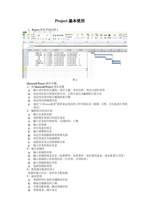
Project基本使用1、Project软件界面如图1图1Microsoft Project操作步骤:1)对Microsoft Project预先设置a)输入项目的有关属性:项目主题、项目经理、项目计划作者等b)设定项目的日程排定的方式:正排计划方式&倒排计划方式c)设定项目的开始日期或结束日期d)设定项目的摘要信息e)通过“工具——选项”菜单设定项目的工作环境信息(视图、日程、日历选项卡等的设定)2)编制项目时间计划a)输入任务的名称b)对特殊任务的日历进行设定c)输入任务的开始时间、完成时间、工期d)输入里程碑e)对任务进行拆分f)输入周期性任务g)设定任务的限制类型和优先级h)对任务进行升级或降级i)连接各任务之间的搭接关系j)输入任务的备注信息3)建立资源库a)输入资源的名称b)输入资源的成本信息(标准费率、加班费率、每次使用成本、成本累算方式等)c)输入资源的工作时间信息(日历型、可用时间)d)输入资源的备注信息e)选择资源的类型4)将资源分配到任务上资源库建立以后,给任务分配资源5)成本管理a)查看时间计划的关键路径信息b)缩短关键路径的工期c)合理分配资源,解决资源冲突d)查看成本,减少支出e)设置项目的比较基准信息f)保存项目信息的比较基准g)显示项目的进度状态h)查看任务进度的差异i)输入任务成本的实际信息j)用挣值分析法评价项目执行的绩效k)文件报表的打印2、新建项目1)单击“新建”。
2)在“项目”菜单上,单击“项目信息”。
如图2图2项目信息设置3)若要从开始日期排定项目日程,请在“开始日期”框中键入或选择所希望的项目开始日期本次设计开工日期为2014年5月10日若要从完成日期排定项目的日程,请单击“日程排定方法”框中的“项目完成日期”,然后在“完成日期”框中键入或选择所希望的项目完成日期。
3、设定项目工作日历根据建设工程项目的特殊情况,施工不分周六日,所以需对每周五天的工作日历进行修改。

Office 课程设计姓名班级学号指导教师3月20 日目录第一次 Word文字排版.............................. 错误!未定义书签。
一: 操作要求................................... 错误!未定义书签。
二: 操作步骤................................... 错误!未定义书签。
第二次 Word图文混排.............................. 错误!未定义书签。
一: 操作要求................................... 错误!未定义书签。
二: 操作步骤................................... 错误!未定义书签。
三: 操作成果................................... 错误!未定义书签。
第三次 Excel电子表格基本应用..................... 错误!未定义书签。
一: 操作要求................................... 错误!未定义书签。
二: 操作步骤................................... 错误!未定义书签。
三: 操作成果................................... 错误!未定义书签。
.................................................. 错误!未定义书签。
第四次 PowerPoint演示文稿制作..................... 错误!未定义书签。
一: 操作要求................................... 错误!未定义书签。
二: 操作步骤................................... 错误!未定义书签。
房屋建筑学课程设计任务书5篇第一篇:房屋建筑学课程设计任务书《房屋建筑学》课程设计任务书——大学教学楼设计——一、设计题目:大学教学楼本工程为某大学拟建的多层教学楼,其功能为学校提供日常教学活动、举办各类小型学术报告以及进行有关课程实践教学的场所。
二、设计条件:(一)建筑规模1.总建筑面积4500m²左右,层数为五-六层。
2.建筑物房间组成和面积:(1)50人左右的普通教室(每间60m²)共30间约1800m²。
(2)50人制图教室(每间90m²)共3间约270m²。
(3)150人阶梯形教室(每间150~180m²)共3间约450~540m²。
(4)50人外语听音室二间约120m²。
控制室约20m²(5)计算机房2间,每间约80~90m2。
(6)美术教室1间约90 m²。
美术器材室1间约30 m²。
(7)教务办公室1间约40m²。
(8)教师休息室每层1间,每间约30m²+10m²(教具存放室间)。
(9)值班室1间约15~20m²。
(10)杂物存放室1间约15~20m²。
(11)厕所:(按2000人考虑,男女比例7:3。
男:每50人设大便器一个,每50人设小便器一个,每90人设洗手盆一个。
女:每25人设大便器一个,每90人设洗手盆一个。
)(12)门厅、走廊、楼梯等根据需要设计。
(门厅按0.04 m²/生~0.08 m²/生)(二)自然条件1.气象条件:常年主导风向为东北风,基本风压650N/m²,年最高温度39℃,最低温度4℃。
2.地质条件:用地地形平缓,地下水位标高约4m,无侵蚀性。
(三)结构类型:现浇钢筋混凝土框架结构或砖混结构。
(四)抗震设防抗震设防烈度为7度。
三、设计要求1.遵循教学规律和特点进行合理的功能分区,流线组织要求明确便捷,空间组合紧凑,总体布局合理。
安阳师范学院建筑工程概预算》课程设计任务书建筑工程学院2012年2 月《建筑工程概预算》课程设计任务书一■设计时间及地点1.设计时间:本次设计时间为1周2.设计地点:各班级教室(也可自选地点)■设计目地和要求1.课程设计目地《建筑工程概预算》是一门实践性很强地课程,必须通过一定时间地动手训练,才能使学生掌握施工图预算地基本原理及基本编制方法,达到教案大纲要求地程度,并为今后地工作打下良好地基础.针对这种要求,按照教案计划地安排对学生进行一次综合性地实践活动,编制一份完整地建筑工程施工图预算,使学生将所学地理论内容进行实务性操作,强化学生实际动手能力地培养,提高学生独立思考.独立解决问题地能力.2.课程设计要求根据课程特点,本次课程设计主要要求学生将以前所学地建筑工程预算课程以及其他相关地建筑构造.建筑施工技术.建筑材料等课程相结合,在教师地指导下,进行系统地.完整地施工图预算编制,主要是掌握其方法,建立其对建筑工程预算地感性认识.各位同学在设计过程中要认真对待,刻苦学习,在有限地时间内圆满完成本次课程设计任务.三■设计题目和内容1.课程设计题目:某工程施工图预算编制(以老师布置图纸为主,也可自己找相关图纸)2.课程设计内容(土建.装饰):(1)熟悉施工图纸,计算工程量.注意图纸是否齐全,尺寸是否有误,有无图纸会审资料.工程量计算时要注意①计算口径一致②计量单位一致③计量规则一致④计算书要整齐,要用铅笔书写,只能涂改,不能誊写⑤计算公式要正确,有时要加注必要地文字.(3)主要材料差价调整,应正确确定主要材料品种及价格地选取.(4)填写工程预算书,按分部分项工程顺序填写,并注明分部名称.(5)复核.(6)编制说明及封面,编制说明中应有编制依据•编制范围及其他应说明地问题•四■设计方法和步骤1.课程设计方法:收集课程设计所需资料:(1)完整施工图纸一套(2)图纸会审记录(3)建筑和结构标准图集(4)预算定额手册(5)费用定额及有关文件(6)建筑材料价格信息(7)有关地工具书•参照《河南省建筑工程工程量清单综合单价( 2008)》计价方法,手工计算分部分项工程工程量,进行工料分析,汇总主要材料,按市场价格调整材料价差,取费计算工程总造价五■设计成果地编制课程设计结束后,要提交以下设计成果,并按顺序装订成册1.封面2.编制说明3.工程费用汇总表六■工程量计算书内容提要1.基数计算(三线一面);2.土石方与基础工程:平整场地.土方开挖.3: 7灰土填料垫层.素混凝土垫层.基础回填土.房心回填土.独立基础.基础梁.构造柱(土0.00以下).地圈梁.砖基础.地沟(垫层.砖)等;3.混凝土及钢筋混凝土工程:梁.柱.板.楼梯.雨篷.挑檐.女儿墙压顶.台阶以及预制过梁等;4.砌筑工程:外墙.内墙.隔墙以及女儿墙等;5.门窗工程:门.窗地制作与安装.木门窗地运输(20km以内)等;6.楼地面工程:地面垫层.防水层.找平层.花岗石地面.水磨石楼面.楼梯栏杆.楼梯.踢脚.散水.卫生间等位置地做法详见工程做法表;7.屋面及防水工程:保温层.找坡层.找平层.防水卷材.雨水口.雨水管.雨水斗等;8.装饰工程:内墙面.柱面.顶棚抹灰.卫生间装饰.外墙面装饰.雨篷.女儿墙及其压顶抹灰等;七■评分标准及成绩评定(一)设计纪律要求1.严格遵守国家法令及有关制度,力求工程造价地准确•2.课程设计中要自主完成,杜绝抄袭现象.3.在正常上课期间所有设计学生可以自由安排设计地点,但是在另行通知地统一答疑时间里,不得无故不到或者迟到和早退.4.由于设计时间较紧,希望同学们克服困难,按时.认真完成本次设计任务.(二)本次课程设计结束后每位同学提交一份完整地预算书.课程设计成绩由指导教师根据预算书质量及设计纪律综合评定.成绩分优.良.中.及格.不及格五个档次.不及格地同学应另行安排补做课程设计.评分标准如下:1.优秀(1)工作努力,遵守纪律•表现好;(2)能按时按量优异地完成任务书中规定地任务,能熟练运用所学理论和专业知识,具有较强地综合分析问题和解决问题地能力,在某些方面有独到见解;(3)预算书完整,内容正确,概念清楚,书写工整,预算书齐全.整洁.2.良好(1)工作努力,遵守纪律,表现良好;(2)能按时按量独立完成任务书中规定地任务,能较好地运用所学理论知识,具有较强地综合分析问题解决问题地能力;(3)预算书完整,内容正确,概念清楚,预算书齐全.整洁.3.中等(1)工作较努力,遵守纪律,表现一般;(2)基本上能按时按量独立完成任务书中规定地任务,在运用所学理论和专业知识上基本正确,具有一定地综合分析问题和解决问题地能力;(3)预算书完备,内容基本正确,概念较清楚,书写较工整,预算书齐全.4.及格(1)工作态度及表现一般;(2)在规定时间内勉强完成任务书中规定地任务,基本达到教案要求,但分析和解决问题地能力较差,在费主要问题上存在错误;(3)预算书内容基本正确,书写较工整,纸齐全,仅有局部非原则性错误.5.有以下情况之一者成绩视为不及格(1)工作不努力,有违纪行为,表现差;(2)未能达到课程设计所规定地基本要求,或课程设计中有原则性错误;(3)弄虚作假,有抄袭行为,或部分内容有其他学生代做;4)预算书模糊不清,内容不齐全.作业参考样张:安阳师范学院建筑工程概预算》课程设计作业姓名专业班级学号指导教师成绩安阳师范学院建筑工程学院2012年月日封面)建筑工程预算书工程名称:建设单位:工程结构:建筑面积:工程造价(土建):经济指标(元/m2):编制单位:二零一二年月日编制说明一.编制依据:1. 采用工程预算定额及材料价格.2. 配套地有关规定.文件.二.造价分析:1. 工程简况2.工程总费用:XXXX .其中建筑费:XXX .措施费:XXX .3.本工程属XX 结构.每平方M造价XXXX元,造价合理.4.每平M 钢筋,每平M 木材,每平M 水泥,每平M 机砖,每平M 用砂,每平M 碎石三.其他工程费用汇总表工程预算表(注:如不够,可附页)技术措施费分部分项表工程名称:第页共页(注:如不够可附页)材料价差表(注:如不够可附页材料价差可参考安阳市或濮阳市建设工程造价信息网发布地最新主要建材价格信息,在此不做补充说明)工程量计算书(注:如不够可附页)。
project课程设计模板一、教学目标本章节的教学目标包括以下三个方面:1.知识目标:学生能够掌握课本中涉及的基本概念、原理和方法,理解课程内容与实际应用之间的联系。
2.技能目标:学生能够运用所学知识解决实际问题,提高分析问题、解决问题的能力。
3.情感态度价值观目标:学生通过本章节的学习,培养对学科的兴趣和热情,树立正确的价值观,认识到学科知识在生活中的重要性。
在制定教学目标时,要充分考虑课程性质、学生特点和教学要求,确保目标具有具体性、可衡量性,以便于学生和教师了解课程的预期成果。
二、教学内容本章节的教学内容以课本为基础,按照教学大纲进行与安排。
具体内容包括:1.教材第一章至第四章的核心概念与原理。
2.各章节重点知识点的讲解与讨论。
3.结合实际案例,分析课程内容在实际应用中的作用。
4.针对不同知识点,设计相应的练习题,巩固所学内容。
教学内容的安排要确保科学性和系统性,使学生能够逐步掌握课程知识,提高实际应用能力。
三、教学方法为了激发学生的学习兴趣和主动性,本章节将采用多种教学方法:1.讲授法:讲解教材中的基本概念、原理和方法,确保学生掌握重点知识点。
2.讨论法:学生针对课程内容进行讨论,促进学生思考,提高分析问题、解决问题的能力。
3.案例分析法:分析实际案例,使学生更好地理解课程内容在实际应用中的作用。
4.实验法:学生进行实验,培养学生的动手能力,加深对知识的理解。
通过多样化的教学方法,使学生在轻松愉快的氛围中学习,提高学习效果。
四、教学资源为了支持教学内容和教学方法的实施,丰富学生的学习体验,我们将准备以下教学资源:1.教材:作为基本教学资料,为学生提供系统性的知识学习。
2.参考书:为学生提供更多的学习资料,拓宽知识视野。
3.多媒体资料:制作课件、教学视频等,以直观的方式展示课程内容,提高学生的学习兴趣。
4.实验设备:为学生提供实验所需的仪器和设备,培养学生的实践能力。
教学资源的选择和准备要充分考虑课程特点和学生需求,确保资源能够有效地支持教学。

Unit4 I used to be afraid of the dark.Section A (1a-1c)Ⅰ. 教学目标:1. 语言知识目标:1) 能够用used to do sth 描述自己或他人过去常常做的事情;发现自己或他人在外表、性格、兴趣等方面所发生的变化。
2) 能运用used to 来谈论过去。
2. 情感态度价值观目标:1)让学生明白事物是在不断发展、变化的道理,培养学生积极向上的心态。
2)Don’t judge a person by his appearance.Ⅱ.教学重难点1. 教学重点:学会描述自己或他人过去常常做的事情基本句型:I used to…2. 教学难点: used to do/be 句型Ⅲ. 教学过程Step1. Leading-in教师与学生通过谈话交流从而引出本单元的教学目标是谈论what you use d to be like. 再展示几张形容外貌及性格的照片,引导学生来描述他们的外貌和性格。
T: hello, everyone. I am your new English teacher, you can call m e Miss He. It’s two years since you came to our school, right?Ss:Yes.T: Yes.Ss: Maybe everyone has changed a little or a lot, right? Now I wa nt to know who has changed a lot in your class. Who?S1: Xu ping. She is taller, and she is more outgoing and friendly and hard-working.T: OK, very good. Today we will talk about what you used to be li ke. Let’s look at some pictures. Who is he?Ss: He is Pan Changjiang.T: Yes, what does he look like ?Ss: he is short.T: what is he like?Ss: He is outgoing.T: Now Let’s do 1a, fill in the chart with words to describe pe ople.Step2. Presentation.引出教学重点以及难点used to 这个词组的用法。
《Project项目管理软件》课程标准一、课程简介本课程旨在介绍与项目管理软件相关的知识和技能,帮助学员掌握使用项目管理软件来有效规划、执行和监控项目的能力。
通过本课程的研究,学员将了解项目管理软件的基本功能和操作流程,熟悉常用的项目管理软件工具,并能够将其应用到实际项目管理中。
二、课程目标- 理解项目管理软件的作用和重要性。
- 熟悉常用的项目管理软件工具,如Microsoft Project、Asana 等。
- 掌握项目管理软件的基本功能,如项目计划制定、资源分配、进度跟踪等。
- 学会使用项目管理软件进行项目计划编制、任务分配和团队协作。
- 能够通过项目管理软件进行项目进度监控和问题解决。
- 培养良好的项目管理软件使用惯,提高工作效率和项目管理质量。
三、课程内容1. 项目管理软件概述- 项目管理软件的定义和作用- 常用的项目管理软件工具介绍2. 项目管理软件的基本功能- 项目计划制定- 任务分配与资源管理- 进度跟踪与监控- 风险管理与问题解决3. 项目管理软件的操作技巧- 软件界面和操作流程- 任务的创建和分配- 进度的设置和追踪- 资源的管理和优化4. 项目管理软件在实践中的应用- 项目计划编制和调整- 任务分配和团队协作- 项目进度监控和报告生成- 风险管理和问题解决四、教学方法本课程将采用以下教学方法:- 理论讲授:介绍项目管理软件的基本概念、功能和操作技巧。
- 实践演练:通过实际案例和练,让学员熟悉项目管理软件的使用方法。
- 讨论互动:与学员进行讨论和交流,分享项目管理软件的应用心得和技巧。
五、考核要求学员参加课程研究后,需完成相关的课后作业和实践任务。
课程考核方式包括但不限于以下形式:- 课后作业:理论知识的巩固和运用。
- 实践任务:应用项目管理软件解决实际问题。
- 个人报告:总结和反思项目管理软件的使用经验。
六、参考资料- 《Microsoft Project用户手册》- 《Asana官方文档》- 《项目管理软件实战指南》以上为《Project项目管理软件》课程的标准。
办公楼课程设计一、课程目标知识目标:1. 学生能够理解办公楼的基本概念、分类及功能布局。
2. 学生能够掌握办公楼设计的基本原则和设计流程。
3. 学生能够了解办公楼建筑风格及其与城市环境的关系。
技能目标:1. 学生能够运用设计原则,进行简单的办公楼平面布局设计。
2. 学生能够通过分析案例,提高观察、思考和解决问题的能力。
3. 学生能够运用所学知识,进行办公楼设计的创意表达。
情感态度价值观目标:1. 培养学生对建筑设计的兴趣,激发创新意识。
2. 增强学生的团队协作能力,提高沟通与表达能力。
3. 引导学生关注建筑与环境的和谐,培养环保意识。
课程性质:本课程为建筑设计初步课程,旨在让学生了解办公楼设计的基本知识,培养学生的设计能力和审美观念。
学生特点:六年级学生具有一定的认知能力和动手操作能力,对新鲜事物充满好奇心,但需要引导和激发。
教学要求:结合学生特点,注重理论与实践相结合,鼓励学生主动参与,培养独立思考和解决问题的能力。
通过课程学习,使学生在知识、技能和情感态度价值观方面取得具体的学习成果。
二、教学内容1. 办公楼概述- 办公楼的定义、分类及其功能布局- 办公楼建筑风格及其与城市环境的关系2. 办公楼设计原则- 设计原则概述:功能分区、空间组织、交通流线等- 结合实例分析设计原则在实际中的应用3. 办公楼设计流程- 设计前期准备:需求分析、场地调研- 设计阶段:平面布局设计、立面设计、景观设计- 设计成果表达:草图、效果图、模型等4. 办公楼设计实践- 办公楼平面布局设计练习- 设计方案分析与评价- 创意表达与展示教学内容安排与进度:第一课时:办公楼概述、设计原则第二课时:办公楼设计流程第三课时:办公楼设计实践(平面布局设计)第四课时:设计方案分析与评价、创意表达与展示教材章节关联:本教学内容与教材中“建筑设计基础”章节相关,涉及办公楼设计的基本知识、原则和流程。
通过本章节学习,使学生掌握办公楼设计的基本方法,为后续深入学习建筑设计打下基础。
某校区办公楼课程设计一、课程目标知识目标:1. 学生能够掌握校区办公楼的基本构成部分,如办公区、会议室、接待区等。
2. 学生能够了解办公楼设计的基本原则,包括空间布局、通风、采光等。
3. 学生能够了解并描述办公楼建筑风格、材料及装饰特点。
技能目标:1. 学生能够运用平面图、立面图等图纸表达办公楼的空间布局和设计理念。
2. 学生能够通过分析校区办公楼案例,提出改进和优化设计方案。
3. 学生能够运用团队协作和沟通技巧,共同完成办公楼设计项目。
情感态度价值观目标:1. 学生培养对建筑设计的兴趣,激发创新意识,提高审美观念。
2. 学生在团队协作中学会尊重他人意见,培养合作精神和责任感。
3. 学生关注建筑与环境的和谐共生,树立绿色环保意识。
课程性质:本课程为校区办公楼设计实践课程,结合理论知识和实际操作,培养学生建筑设计和团队协作能力。
学生特点:学生具备一定的建筑基础知识,对设计有浓厚兴趣,善于合作和探究。
教学要求:注重理论与实践相结合,关注学生个体差异,鼓励创新思维,提高学生综合运用知识的能力。
通过课程目标分解,确保学生达到预期学习成果,为后续教学设计和评估提供依据。
二、教学内容1. 建筑设计基本原理:讲解建筑设计的基本原则,包括功能分区、流线组织、空间布局、通风采光等,对应教材第二章。
- 办公楼功能分区及空间组织- 办公楼流线设计和优化- 通风、采光与景观设计2. 办公楼建筑风格与装饰特点:分析不同建筑风格的办公楼设计,介绍装饰材料及特点,对应教材第四章。
- 现代办公楼的建筑风格- 装饰材料的选择与应用- 室内外装饰设计要点3. 办公楼平面图、立面图绘制技巧:教授如何运用图纸表达办公楼设计,对应教材第五章。
- 平面图、立面图的基本知识- 办公楼图纸绘制技巧- CAD软件在办公楼设计中的应用4. 案例分析与设计实践:通过分析校区办公楼案例,指导学生进行设计实践,对应教材第六章。
- 校区办公楼案例解析- 设计方案构思与表达- 团队协作与沟通技巧5. 绿色环保与可持续发展:强调建筑与环境的和谐共生,介绍绿色建筑相关知识,对应教材第八章。
届课程设计说明书工程量清单的编制院、部:学生姓名:指导教师:专业:班级:完成时间:学院专业:《建筑工程概预算》课程设计实施细则一、课程设计的目的通过课程设计要求每位同学独立完成一份某土建工程的工程量清单编制工作。
通过对实际工程清单计价编制工作的操作,使学生掌握使用工程清单计价规范确定工程造价的实际操作方法,加深对建筑工程概预算课程相应内容的理解和掌握,做到理论联系实际,对建筑工程概预算有系统的认识。
二、课程设计内容与要求课程设计具体的内容包括:1、会审图纸:对收集到的土建、装饰施工图纸(含标准图),进行全面的识读会审,掌握图纸内容。
2、编制工程量清单:根据施工图纸和《建设工程工程量清单计价规范》(GB50500-2013)和《房屋建筑与装饰工程工程量清单计算规范》(GB50854-2013),/表格方式计算工程量,编制工程量清单。
三、设计的方法步骤1、熟悉图纸、收集相关资料,学生通过看图纸(含标准图),对图纸所描述的建筑物有了基本印象,对图纸存在的问题全面提出,指导教师或工程技术人员进行答疑和问题处理。
2、划分项目、确定分部分项清单项目名称、编码3、确定分部分项清单项目拟综合的工程内容4、计算分部分项清单主体项目工程量5、编制清单(分部分项工程量清单、措施项目清单、其它项目清单、规费和税金项目清单)6、复核、编写总说明7、装订成册四、指导教师资格及职责1、教师资格:指导教师必须由具有讲师及以上职称或硕士研究生及以上学历教师担任(优先选择具有工程实践经验的教师)。
2、指导教师职责:指导教师负责学生的分组与课题选题;每组学生可安排1~2人,选定一课题。
每位指导教师指导课程设计的学生不能超过一个自然班。
如学生数量较少,也可以根据实际情况教师下达课程设计任务书,指导、督促、检查学生课程设计的进行情况,课程设计完成后负责学生的成绩考核。
五、时间安排及成绩考核(一)时间安排按照大纲要求,本课程设计要求在2周时间内完成,采取集中或分散的方式进行,时间安排可参考如下:(一)熟悉图纸(20%)(1)了解项目基本概况以及相应的技术参考标准;(2)找出项目工程量计算过程中的难点,并互相讨论.(二)清单项目列项及计算(80%)(1)项目编码以及项目特征的描述要正确;(2)有无出现清单项目漏项错项的情况。
广联达办公大厦课程设计一、课程目标知识目标:1. 学生能理解并掌握广联达办公大厦的基本设计原理,包括建筑结构、材料选用及空间布局。
2. 学生能描述并分析广联达办公大厦在绿色建筑、节能减排方面的特点及优势。
3. 学生了解建筑设计与人文、环境、经济等因素的相互关系。
技能目标:1. 学生能运用CAD软件绘制广联达办公大厦的平面图和立面图。
2. 学生能运用BIM技术对广联达办公大厦进行三维建模,并进行简单的数据分析。
3. 学生具备团队协作能力,能在项目中进行有效的沟通与协调。
情感态度价值观目标:1. 学生培养对建筑设计的兴趣和热情,增强对建筑学科的认识和认同。
2. 学生树立绿色环保意识,关注建筑与环境的和谐共生。
3. 学生通过本课程的学习,培养创新精神和实践能力,激发对建筑行业的热爱。
分析课程性质、学生特点和教学要求,本课程旨在帮助学生将理论知识与实际操作相结合,提高学生的综合运用能力。
课程目标具体、可衡量,便于教学设计和评估。
在教学过程中,注重引导学生主动探究、积极实践,培养学生解决实际问题的能力。
二、教学内容1. 建筑设计基本原理:包括建筑物的结构、材料、空间布局等方面,对应教材第二章。
- 广联达办公大厦建筑结构分析- 广联达办公大厦材料选用及优势- 广联达办公大厦空间布局特点2. 绿色建筑与节能减排:探讨广联达办公大厦在绿色建筑、节能减排方面的设计理念,对应教材第五章。
- 绿色建筑标准与评价体系- 广联达办公大厦节能减排措施- 建筑与环境保护3. 建筑设计软件应用:学习CAD、BIM等软件在建筑设计中的应用,对应教材第六章。
- CAD软件绘制平面图、立面图- BIM技术三维建模及数据分析- 建筑设计软件在实际项目中的应用案例4. 团队协作与沟通:培养学生团队协作能力,对应教材第八章。
- 项目管理基本原理- 团队协作方法与技巧- 沟通与协调在实际项目中的应用教学内容安排和进度:本课程共计16课时,按照以下进度进行教学:1. 建筑设计基本原理(4课时)2. 绿色建筑与节能减排(4课时)3. 建筑设计软件应用(4课时)4. 团队协作与沟通(4课时)教学内容科学、系统,注重理论与实践相结合,旨在帮助学生全面掌握建筑设计与实践技能。
(1)让学生填写完整空格(2)全班读b.复习I’m= I am(出示头饰)T: Hi, I’m Wang Bing. I am Wang Bing.出示I’m= I am让学生用自己的名字说Hi, I’m… I am…2.拓展My name is…a.教师出示Yang Ling.和PPT中杨玲的自述T: Look, Yang Ling is here, too.PPT(录音):Hello. Hello. I’m Yang Ling.I am Yang Ling. I have a doll. T:Please try to read it.b.杨玲的小诗T:Yang Ling can say a rhyme. Let’s listen it together.出示: Hello. Hello. I’m Yang Ling.I am Yang Ling. I have a doll.My name is Yang Ling. I love dolls.(配着节奏的音乐)教师出示:My name is…板书:My name is…教读My name is…PPT:My name is = I’m =I amT:My name is equals I’m.PPT:Try to read(教师拿出Yang Ling 的头饰)出示: Hello. Hello. I’m Yang Ling.I am Yang Ling. I have a doll.My name is Yang Ling. I love dolls.(配着节奏的音乐)让学生读小诗,打拍子4.Review:Good morning.Good afternoon.Good evening.a.Play a game---看图猜句子出示一些图片,让学生猜用哪句句子。
b.出示句子,读句子Good morning/afternoon/evening.c.Let’s chant.Good morning.早上好。
NEW OFFICE BUILDING PROJECT Organizational Arrangement for ConstructionNAME: Chen Jie (陈杰)STUDENT ID: 110056008MAJOR: Civil EngineeringContentsⅠ. Project Profile (3)Ⅱ. The Main Construction Method (5)Ⅲ. Construction Schedule Chart (19)Ⅳ. The layout of the jobsite (21)Ⅰ. Project ProfileThis project lies in the Xiaoheshan high education areas of Hangzhou City, near the Xixi wet land. The floor area is about 3117 m2. It is invested by Zhejiang University of Science and Technology, designed by NO.101 Civil Engineering Designing Institute Xiaoheshan Construction Limited Company. This planning project will be the Office Building, and the total construction time will be 100 days.1.1 Office Building1.1.1 The plan size of the building is 64.6m*13.2m, and the constructure form is steel concrete frame. Cornice height: 13.4m. The indoor and outdoor difference is 0.45M.1.1.2 The foundation work: C40 reinforcement concrete pilecaps, C30 foundation beam. The MU10 steam pressure sand-lime bricks are applied for the brick foundation laid with M7.5 mortar.1.1.3 The superstructure: C40 reinforcement concrete frame columns, and C30 beam and floor. Concrete small cavity blocks with strength grade of MU10 are to be adopted for the frame filler wall. Thickness of theinterior masonry wall shall be 190mm, M5 mixed mortar shall be used for the brickwork with elevations higher than -0.060, MU10 autoclaved lime-sand bricks and M7.5 cement mortar bricks shall be used for brickwork with elevations lower than -0.060. Besides, waterproof mortar with blending propotion of 1:2 shall be plastered with thickness of 20mm.1:2 cement mortar (blended with water-proofing additives equivalent to 5% of the cement weight) shall be plastered to the elevation of -0.060 with thickness of 20mm for the wall body horizontal damp-proof coating.1.1.4 Roof work: on the cast-in-situs slab, the sequential layer as follows: 1:10 cement perlite sloping leveling minimum THK.30mm; Spread the APP bitumen waterproof book of the APP.4mm; Squeeze the mold foam the plank, 140mm; 1:2.5 cement mortar leveling THK. 20mm; Waterproof book of PVC, 1.5mm; Moisture retention / protection mat; Drainage board; Soil work the cloth protect the mat; Light-weight the artificial synthesize soil. 120mm; Vegetation.1.1.5 Finishing and Decoration Work: Outer wall decoration, the wall is smoothed by 1:2.5 cement mortar with thickness in 20mm, and 30 thicked dull-finish granite; Inside decoration: Hot galvanized coating is painted on the surface of the keel of the supended ceiling, the keel can be dismantled by hand for the maintenance of the air-conditioners and electromechanical equipments of power lines; Light-weight partition wall: Adopt steel keel bi-layer fire proofing gypsum plate partition wall. Thekeel adpots hot galvanized zinc plate of Series 75 with thickness of 1.0mm and 1.5mm.1.1.6 Flooring Work:(1)Meeting room office: carpet thickness is 3mm; (2)Hall, tea room, storage room: waxing fire plate black granite 600*600*20 cement adhersive 5 thick; (3)Canteen, corridor: 3.5mm thick rubber floor; (4)Testing rooms and office, IT offices: 5mm thick rubber floor; (5)Main computer room: 1mm of gravity flow epoxy daub layer; (6)Sanitary room, cleaning room, tea house: anti-slipping floor 5mm.1.1.7 Doors and windows work: External all alloy window adopts hollow glass with coating film an low radiation, and the frame adopts the bridge-cutting energy saving. Steel frame should get hot galvanizing and anti corrosion treatment and the alloy window is treated with anodizated compoundd film, thickness ≥7.5μm.1.2 Substation & Gate house1.2.1The building area for Substation & Gate house is 316.38m2, and the structure form is one floor reinforcement concrete frame.1.2.2 The foundation is independent column base, the pilecap and foundation beam is C25 concrete.Ⅱ. The Main Construction Method2.1 The Main Construction Method for the Civil Work2.1.1Technological Process for Site Execution2.1.1.1 The Foundation Work2.1.1.1.1Make the alignment—Plain concrete blinding, and make curing—make the alignment—foundation reinforcement binding—set up the formwork—casting concrete—make curing, remove the form--lay the foundation wall, embed the pipes and what ever required—backfill, level the site2.1.1.2 The Super-Structure2.1.1.2.1 Make the alignment—set up the column reinforcement steel –make the form work—cast the concrete—make curing, remove the form--fix the beam and slab reinforcement steel and the form —cast beam and slab concrete—make curing, remove the form—lay block work for the wall2.1.1.2.1During the execution of the super-structure, reasonably organize the work force with the form work and concrete casting as the core. We will have our work forces of different trade to work continuously to avoid them from sitting idle. The project management will carry out the execution in a way as the assemble line works and various groups will work orderly and in turns. When the main structure is completed, block and brick laying for the walls will be executed from the ground floor to roof. Indoor decoration and exterior work may start in the early stagein order to guarantee timely completion as planned.2.1.2 The Method for the Main Items2.1.2.1 The Earth Work2.1.2.1.1The foundation of this project mainly consists of separate piers. The concrete volume of the foundation work is considerably large. The working procedures are numerous, the techniques are complex, high qualities are required and the time is pressing. So it is necessary to do well the pre-construction preparations, and to adopt effective technical and organizational measures so as to ensure the foundation work to be completed soonest possible with high qualities and thus creating favorable conditions for the super struc ture’s execution.2.1.2.1.2 The excavation will be controlled as 20cm higher than the blinding bottom level and then the rest will be done manually. And the bearing layer of the soil is never to be removed. We will get in touch timely with the Client, the designing institute in case that the soil conditions do not comply with those in the soil investigation report or any accidents happen.2.1.2.1.3 The soil for backfill will be piled up at site and the edge of the pile should be away from the foundation pit less than 3 meters.2.1.2.1.4 It is imperative to invite those from the designing institute, the supervisor and other related units to check the work asthe excavation of the foundation pit is completed. The following work can not be started until the result of the said check is ok.2.1.2.1.5 We will invite the supervisor and quality control unit to check the foundation work when the same is done. When the check gives ok, the backfill is to be carried out. The backfilling shall be done simultaneously both in and out of the foundation pit to avoid from the uneven side load. And compaction is made well.2.1.2.2 The Moulding board Work2.1.2.2.1 The dimensions of the moulding board shall be correct and surfaces even, having sufficient bearing capacity, rigidity and stability to reliably bear the weight of the concrete newly cast and its side pressure, and other load during the execution. The moulding board should be easy to be fit and dismantle. The moulding board work shall facilitate the reinforcement steel to be bound and fit, the concrete cast and curing. The moulding board work shall be made economically to the extent to satisfy the lifting demand and to reduce the joints with largest possible area.2.1.2.2.2 The Adoption of the Moulding board System: The moulding board work system is selected and decided as the following: firstly it should be advanced, reasonably economic and applicable; secondly, it should be of help in control the project quality and of benefit to the effect of fair face for the main structure; thirdly, it is low in costwith less investment. All in all, we have to consider the economics and applicability and thus adopt the scientific and reasonable form work system. It is imperative to improve the design of the washers and the counter bolts so as to ensure the rigidity of the form but the cycles less than steel moulding board.2.1.2.2.3 Scaffolds shall be mounted tightly before doing the form work. Before casting, it is imperative to check all the support if they are strong, and if the clips and clamps are properly tightened. When casting, those who have made the moulding board work have to be on the spot and watch the ongoing form work, check the supports now and then to see if there any movable or deformed, and mend in time if needed. It is also imperative to frequently check the crane hook, and see if the bolts and nuts are loose between the slant supports and the platform. Timely removal is needed if any happens.2.1.2.2.4 When making the form work for RCC beam and slabs and their spans are more than 4 meters, the arch shall be made. If there is no specific requirement, the height of the arch shall be 1/1000-1/3000 length of the span.2.1.2.2.5 When removing the form, neither big hammer is used nor other unreasonable ways. If it is difficult to remove the form, claw bar may be applied gently at the bottom. Proper distances shall be maintained between the form and the walls when lifting so as to ensure no breaks madeto the concrete faces, edges and corners.2.1.2.2.6 When removing the side moulding board for beams, neither edges nor corners shall be broken. Concrete cubic for testing shall be kept with the same conditions to facilitate the removal of board at the correct time. The board shall not be removed until the cubic is as strong as 1.2MPA. Experiences to tell when 1.2MPA shall be gained during execution for different grades of concrete with various cement, on different temperatures and etc. Finally one can tell when to get 1.2MPA by his experiences.2.1.2.2.7 The surfaces and joints of the board shall be cleaned immediately after the removal to ensure no stick occurs for the next casting. The board shall be repaired and cleaned after using. Remedies shall be made if any deform happens and parts shall be replaced, etc.2.1.2.3 The Reinforcement Steel Work2.1.2.3.1 It is a must to check and test the reinforcement steel brought into site. The checking shall be made including: to check its marks, outlook and take random samples to be tested as per the present state standards. The steel can only be used until the check is ok.2.1.2.3.2 Before fabricating, the steel bars shall be cleaned without any damage. Paint stains and rust shall be cleaned up before using.2.1.2.3.3 In order to ensure the correct dimensions of the steel work, special tools like clamps can be made to control the same.2.1.2.3.4 During execution, the binding joints shall be not in one line. The center of the joint to the overlap length (L1) shall be less than 1.3 L1. The percentage (the cross section of the steel bars under stress with binding joints be divided by the total cross section of the bars under stress) shall comply with the stipulation: the length under stress shall be less than 50%. S(net space) shall no be smaller than D (diameter) but not small than 25 mm.2.1.2.3.5 For welding, it is imperative to check the joint’s outlook, the joint itself, the bent angle(no greater than 4 or 70/1000) and the axis deviation. The joint shall be away from the inflexion (greater or equal to 10D). During execution, cut the bar end even, first weld the high level bars and then the lower ones.2.1.2.3.6 The proper concrete cover and the location of the reinforcement steel shall be checked. It is the main checking for creating the first class quality work for many problems happened in this regard. Cement mortar and plastic spacers made of are used to control the concrete cover. The spacers are usually fixed on the top of the column reinforcement steel and at bottom, plastic ones, to control the concrete coverage.2.1.2.3.7 When fabricating, attention shall be paid to the space between bars and their diameters. The anchor length shall comply with the requirements of drawings and the specifications. For those cantilever structures, the reinforcement steel hall be positioned properly and theconcrete cover shall be ensured. No stirrups are missing and the end of the binding seams shall be bent inward to avoid the concrete surface from being stained and rusted.2.1.2.4 The Concrete Work2.1.2.4.1 Before execution, the concrete mix ratio shall be designed. Based on the features of the materials at site and the technical requirements of the concrete, calculations shall be worked out and adjustments shall be made in the lab so as to obtain the proper concrete mix ratio which complies with the design and technical requirements for the execution and is also reasonably economic.2.1.2.4.2 Before concrete casting, form work, reinforcement steel work and those hidden items shall be checked. For formwork, check its level, position, parts and elements to see if they all comply with the designing requirements. Check the arch if it is correct. Check the joints, corners supports, reinforcement steel, embedded elements and their numbers, locations, welding points, water and electrical pipes, ventilation ducts and shafts, their numbers and locations, and etc, till all these comply with the designing requirements and specifications. Checks are carried out within the work groups, among the work groups of different trades, and by the professional quality inspectors and then submit to the Supervisor and the representatives of the Client for approval. Only whenthe above- mentioned checks including on hidden items are completed without finding any mistakes, can concrete casting be carried out. During casting, carpenters and rebar men shall be at the spot to ensure that no deform of either form work or reinforcement steel happens.2.1.2.4.3 Casting for the main project structure twill be dong by the concrete pump. So the concrete shall comply with the intensity and endurance by the design requirements and specifications, and also conveyable through the pipes by the pump. In order to guarantee the execution quality and progress target, it is imperative to choose the ready made concrete supplier with good credit and rather powerful, who supply the concrete up to the state standards. Besides, the quality of the materials shall be strictly controlled.2.1.2.4.4 The execution method:(1)Before discharge, the trans-mixer shall properly mix 30 seconds;(2)Before pumping the concrete, all the water in the storage drum and pipes shall be cleared away, then add the same mix ratio mortar (1:2 cement mortar) to lubricate the pipes. After that discharge the concrete;(3)when starting, the operator shall pump the concrete at rather low speed, and then speed up until normal operation. If the concrete supply is not in time, keep the slow and continuous pumping. (4)Before pumping coming to an end, work out the volume of th concrete needed and inform the batching plant of the same;(5)Trans-mixer should be timely cleaned after casting.2.1.2.4.5 Casting procedures by the pump:(1)From far away to closer places;(2)For the same area, first the vertical structures, then the horizontal ones, layer by layer;(3)If no joints are permitted, the time difference between two areas or two layers shall not longer than the time concrete sts.(4)When casting, if the lower layer of concrete has set, then joint has to be made between the upper layer and the lower one.2.1.2.4.6 Vibrations shall be made by professionals and in so doing: prompt insert the vibrator and slow pull-out, avoid from prying; make vibration about 20-30 seconds for each point and always avoid from making over-vibrations. Also avoid from hit the reinforcement steel, form, rings, embedded plates or units. The insertion of the vibrator head shall be no less than 50 cm.2.1.2.4.7 During casting, professional carpenters shall watch the form work. Should any deform or displacement happens, immediately stop casting and make remedies, which shall be completed before the set of the concrete already cast.2.1.2.4.8 12 hours after casting, the concrete shall be covered and cured with water. For the concrete made of Portland cement and iron Portland cement, the sad time shall not less then 7 hours. For the concrete with slow set additives or barrier property, the said time shall not less than 14 hours. Watering shall be made as frequently as to keep the concrete wet and damp. In summer, make more frequent watering to ensure its surfacebeing wet and carefully cover it with polythene sheet, avoid from cracks appearing.2.1.2.4.9 Take protective measures for the surfaces of those slabs and staircase steps already completed casting. When the rigidity is 1.2MPA, people may step on them. To avoid the slab from deforming and cracking due to carrying load too early, the welding machine and the steel bars shall not be directly laid on the slabs cast at site.2.1.2.5 The Brick and Block Work2.1.2.5.1 MU10 standard bricks shall be laid with sand cement mortar in this project. The exterior wall above 0.000 level shall be made with multi-hole blocks. The interior wall shall be made of concrete blocks 200mm in thickness.2.1.2.5.2 Before starting the brick and block work, make level of the surface of the foundation and the different floor surfaces, mark the axis, sideline and opening for the first layer.2.1.2.5.3 Mix the mortar by the mortar-mixer and strictly follow the mix ratio.2.1.2.5.4 The arrangement of the bricks and blocks shall follow the drawings. The blocks are laid in the way: upper layer and lower layer are off set joints, the overlap shall be half of the block length but neither smaller than one third of it height, nor smaller than 90 mm. If the overlapdoes not comply with the requirement, steel plates shall be applied as per the stipulations for block work design.2.1.2.5.5 For exterior wall corner and cross joints, blocks shall be laid with overlaps every other layer.2.1.2.5.6 Positioning and Correction: It is not advisable to make watering on normal blocks of small size. When the weather is hot and dry, one may spray some water on the blocks. The blocks with less than 28 curing days shall not be worked with. Their rigidity shall comply with the design requirement. Their surfaces shall be cleaned and then move to the work place. The block work shall be made in the way as: first far away places, then closer; first lower layer then upper layer; first exterior wall then interior wall; start from the corner or the positioning block for each layer; correction shall be made when one layer completed; the level and flatness of the wall shall be well controlled.2.1.2.5.7 The wall shall be executed one layer after another and no step-shape wall is allowed. The height of the wall made daily shall not more than 1.8 meters.2.1.2.5.8 The cross corners and corners shall be made simultaneously. The teeth-shape wall are not acceptable. The horizontal projection of the step-shape wall shall not be smaller than two thirds of it height.2.1.2.6 The Roof Water-proofing Work2.1.2.6.1The roof work is one important part of the construction project. The roof work quality is closely related to that of the project. To ensure the roof work quality we have to apply comprehensively the administrative and professional techniques, and scientific methods with the roof structure, its capability, function and outlook as the control points.2.1.2.6.2 Identify the slope, mark the lines, start from the parapet, in the order of ditch and discharge, make the layout to control the level and slope. The slope must comply with the design requirements. The water trap for discharge shall be made as a small pit. The slope shall be smooth for discharge the water. The surface of the screed shall be compacted and easy for water discharge. When the mortar sets, smoothen with a trawl. Finally remove gently the wooden strips used to separate the whole roof.2.1.2.6.3 The Insulation work: On the surface of the screed apply one layer to separate from the air. Then fix the insulation. It should be level, dry and clean. The insulation blocks shall be fixed close to each other, and overlap properly between the upper and lower layer.2.1.2.6.4 The Protection Layer work: Properly fix the joints and the squares as per the design requirements. Thoroughly clean before casting. Ensure the thickness and the slope. Smoothen the surface with an iron trawl when mortar sets. Then cover the roof with straw bags and make curing for 14 days. No bod is allowed to step on the roof during thecuring period.2.1.2.6.5 Water-proof Layer: The base course shall be level and smooth, the slope complies with the design requirements, no grains of sand, dust and etc. The water content shall not be more than 9%.2.1.2.7 The Decoration Work2.1.2.7.1 As per the progress of the civil work, many temporary stores for civil work are empty. They may be used for the decoration products and semi-products. Those temporary stores shall be closed and equipped with guards to prevent the said materials from being accidentally damaged and dirtied.2.1.2.7.2 Cleant and wet he walls before working on them. Water the wall wet through one day before plastering. Hollow blocks shall be wetted 2 days in advance and more than twice a day (It depends on the weather conditions at site.)2.1.2.7.3 Before plastering check the walls if they are level, vertical and etc. Then make cakes and guidelines for plastering. The upper cakes are on the height of 1.80 m while the lower cakes just above the top of the skirt. Guidelines or control lines may be made between the cakes as references for the work of rendering.2.1.2.7.4 The mortar for plastering shall be strictly measured and mixed. The mix ratio and the density is subject to the approval. The mortar mixed with cement and gypsum shall be used up before it first sets.2.1.2.7.5 The Technological Process of Plastering: Close the gaps around the doors and windows—clean the walls—splash water and wet the walls—check the walls if level ,vertical—make cakes and guidelines—fix the corner protective strips—plaster the windowsills—plastering: first course, second course—fix the separate strips—smooth the surface course.2.1.2.8 The Paint Work2.1.2.8.1 Paint is applied for the surface of block and brick walls. So it is necessary to smooth the plastering surface and wet the wall with brushes. Keep curing for 7 to 14 days under the normal temperature. When the water content is less than 10%, paint can be done. Before painting, fully stir and mix well, and make it without any sediment.2.1.2.8.2 Technical Process: Base course plastering—first coating of putty—second coating of putty—paint2.1.2.9 The Door and Window Work2.1.2.9.1 There are various doors and windows in the project. They shall be manufactured as per the requirements and products and semi-products shall be stored separately. Doors and windows of different kinds shall be carefully checked before installation.2.1.2.9.2 The installation of the doors and windows for this project shall be done with the method of fit-in. The window frames are forbiddento be fixed by fastening bullets. Before installation fabricate concrete blocks similar to the bricks and fix them properly when laying the bricks. The steel plate embed in the block is used to connect the window frames. The installation of the door frames is to connect the wooden blocks embed in the walls. The frames of the door and window work are executed with the wall work. So after the installation of the frames the other work is still going on at site. Workers have to take measures to protect the door and window frames already fixed and no damages will happen to the same.2.1.2.10 The Scaffolding Work2.1.2.10.1 The scaffolding work is made with steel pipes and clips with safety net tied around. The base for the vertical pipe shall be leveled and compacted solidly. The water is easy to be discharged at site and no water will gather around on the ground surface.2.1.2.10.2 The distance between the inner and outside bars is 1.0m, the row space 1.5-1.8m, the height of each layer 1.8m and the distance between the wall and the inner bars,20-30cm. the longer and shorter bars are 10-20cm out of the scaffolding. The whole scaffolding is supported with bridgings thus forming a complete system.2.1.2.10.3 The Removal of the Scaffold,the removal will be done from the top to bottom. Take away whatever has been removed. The ties to the wall to fight against the wind shall not be moved in advance. The twobridgings at the ends shall be removed after the middle ones. Special attention shall be always paid to the completed products. Also protect the original point for settlement observation.2.2 The Main Construction Method for Finishing Work2.2.1 Main construction measure for outer wall2.2.1.1 Before the panel of veneer’s installation, should follow the requirements of the building design drawing, verified the physical dimension of installing position of the decorations panel and deviation situation conscientiously at first. For example, vertical degree, roughness and the matrices of wall the size that is increased and decreased. Then work out the amended drawing. There should reconfigure the board if the difference goes beyond the allowed deviation. And this reconfiguration should base on the premise that matrices and distance of surface of decorations panel are not smaller than 50MM. Follow the building design drawing to mark the installed line on the wall, and guarantee the size to be correct. If seam width of panel design of the decoration has no requirements, should accord with the regulations of relevant norms.2.2.2 Construction method of the light weight partition wall2.2.2.1 The partition wall of this project adopts the light-weight steel fossil fragments gypsum board, its craft installation as follows:Put the line for the wall after the structure is confirmed----the construction of wall base-----install the ground keel and shed keel------ Fix various entrances cave and doors---- Install one side gypsum board----- The water and electricity pipe piercing through the line and confirming------install another side gysum board------the joint work-----Connect fixed apparatus, electric----the decoration for wall----Construction for skirtings.Ⅲ. Construction Schedule Chart3.1 Construction Schedule ChartDuring the construction management, apply planning management method to bring each link of construction into the track of plan, and strictly execute various regulations in the plan.The following plan has been carried out during the construction management of the project: Overall schedule control plan.Ⅳ. The layout of the jobsite 4.1 The layout of the jobsite。