容器设备常用计算表
- 格式:xls
- 大小:223.50 KB
- 文档页数:8
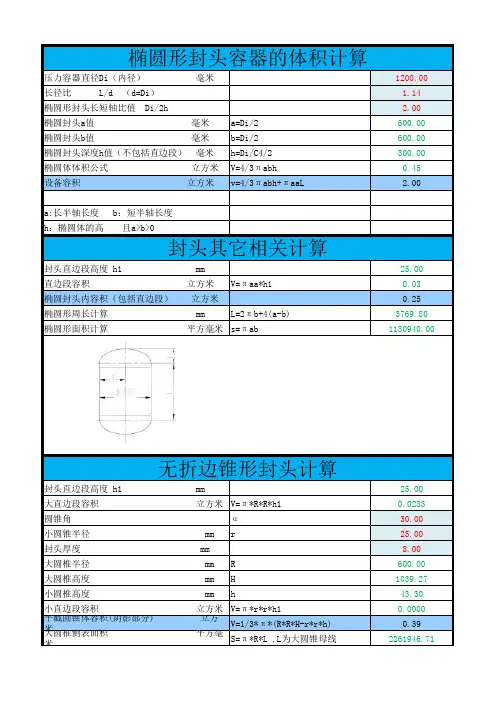

1、计算条件容器设计压力p=0.6MPa 容器壳设计温度t=50℃设计温度下材质许用应σ]=容器筒体内直径Di=2800mm 容器总高度Ho= 容器筒体名义厚度δn=12mm 支撑高度/支座底板离地面 厚度附加量C=C1+C2=1mm 支座底板到壳体质心 壳体保温层厚度δt=0mm 偏心载荷Ge= 操作状态下设备总质量mo=35000kg 偏心距Se=2、水平风载荷实取风载作用外直径D0=2824mm考虑到公式计算值可能不全面 风载作用外 设置地区10m高度处的基本风压qo=550N/m2 查GB50009 壳体质心距地面高度H t=附录E中表E.5风载荷Pw=12114.96N 风压高度变化3、水平地震力 重力加速度g=9.81m/s2 地震载荷Pe= 地震影响系数a=0.24按表20选取水平载荷P=4、支座承受载荷 选用支座型号:A1JB/T4712.3表3~表5支座数量n= 支座的筋板和底板材料:Q235A 支座本体允许载荷[Q]=250KN不均匀系数k= b2=280mm计算支座安装尺寸D = l2=300mm 查JB/T4712.3表3~表5s1=130mm实际支座安装尺寸D =δ3=14mm 支座实际承受=5、支座处圆筒所受支座弯矩校核(带垫板支座)支座载荷校 设计温度下筒体材料许用应力[σ]=113mm支座处圆筒所受的支座 筒体有效厚度δe=11mm 由此查找[ML]设计压力p=0.6MPa 壳体许用弯矩[ML]=支座处圆筒所受的支座弯矩校支座尺寸容器壳体材质:Q235B许用应力[σ]=113MPa 查许用应力表容器总高度Ho=6500mm离地面高度H=5000mm体质心距离h=1500mm偏心载荷Ge=10000N偏心距Se=2000mm作用外直径D0=2824mm体质心距地面高度H t=6500mm 按此值及地面类别选取系数fi 度变化系数fi=1按Ht及地面类别查表22地震载荷Pe=82404N水平载荷P=85432.74N支座数量n=4一般为4个,承受静力载荷,直径≤700mm的容器可以采用2个不均匀系数k=0.83支座安装尺寸D=3178.222mm支座安装尺寸D=3178mm际承受载荷Q=153.0478KN载荷校核结论:合格!的支座弯矩ML=26.01813KN.m用弯矩[ML]=37.34KN.m 以[σ]、δe、p查JB/T4712.3附录B中表B.1~B.4并采用内插法弯矩校核结论:合格!内插法公式:X1=0.8 Y1=0.026968X=0.866667 Y=0.032675X2=0.9 Y2=0.035529。
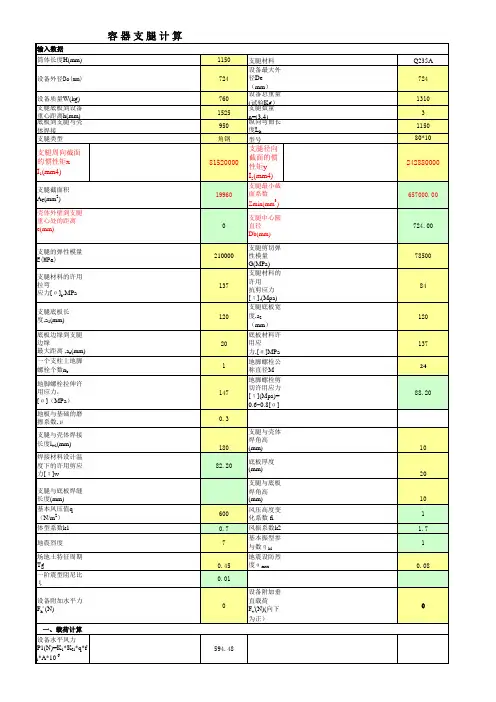
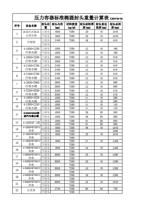
![最新容器支腿计算公式(支腿计算主要用于立式容器的支腿受力及地脚螺栓计算)[表格]](https://uimg.taocdn.com/679ee3732f60ddccdb38a025.webp)

设计压力,MPa 常压加固柱型号HW300X300X12X12设计温度,℃50加固柱截面系数,cm³1115容器长L,mm 10000加固柱间距L p,mm450容器宽W,mm 6000型钢和宽度W方向水平布置,底板型钢支撑实际跨距,mm200容器高H,mm 8000加固圈型号等边角钢50X50X5型钢材料Q235A 加固圈惯性矩,cm411.21壁板材料Q235A 顶边加固件型号等边角钢50X50X5设温壁板材料许用应力[σ]t,MPa 135顶边加固件惯性矩,cm411.21常温型钢许用应力[σ]b,MPa135介质名称水材料弹性模量E t,MPa 191000介质密度ρ,Kg/m31000顶板加强筋型号等边角钢100X100X12顶板加强筋沿L方向上的间距A=L T,mm200钢板负偏差C1,mm0.8钢材密度ρM=,Kg/m³7850顶板加强筋截面系数,cm³29.48顶板加强筋沿W方向上的间距B=W T,mm200腐蚀裕量C2, mm2底板厚度δbn,mm8拉杆近似直径,m m 26.2211623拉杆直径,mm加速度g,N/Kg9.81顶板名义厚度δT ,mm4实际的加固圈数量及各段间距H1,mm H2,mm H3,mm H4,mm H5,mm H6,mm4250016001500130011000推荐的加固圈数量及各段间距H1H2H3H4H5H61480032000000 2360024002000000 3296020001680136000 4248016801440128011200各段壁板厚度δin,mm 101618181801.设计条件示意图。


0第1页共11页01020304050607080910111213141516171819202122232425262728a 29r 30r 31323334常温许用应力材料密度材料数据地脚螺栓材料许用应力地震设防烈度试验压力焊接接头系数9本文件内容为北京石油化工设计院技术成果,未经本院许可,不得转让或复制给第三方。
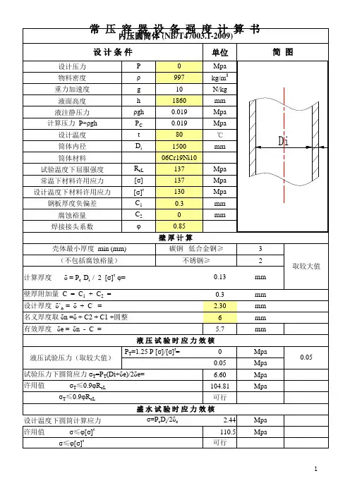
T h i s d o c u m e n t i s t h e p r o p e r t y o f B P D I . U n a u t h o r i z e d d i s c l o s u r e t o a n y t h i r d p a r t y o r d u p l i c a t i o n i s n o t p e r m i t t e d .许用应力1400设计基本地震加速度计算条件(一)设计温度 版 次计算压力100设计压力0.85校 核审 定审 核例题设备图号13.001工程名称设备位号卧式容器计算表(JB/T4731-2005)容委会详细设计设计阶段V111E511编 制170设计温度下的弹性模量7850材料密度度0.125-0.1-0.10.40g0.323452.05E+052.05E+05设计温度下的许用应力常温屈服强度0.1基本数据17016MnR圆筒材料常温弹性模量常温许用应力7140厚度附加量椭圆封头103尺寸数据一名义厚度半球形封头鞍座封头封头类型有效厚度材料碟形封头封头材料设计温度下的许用应力16MnRQ235-A.FQ235-A170n ny 0封头曲面深度6501707850[]tσ[]σ1αφTp c p pTeL R EtE sγMPa MPa MPaC ︒MPa MPa MPa MPa MPaMPa MPa[]h σ[]t hσhγMPa []saσmm mm mm mmmmheδhδhC MPa []btσ3/m kg 3/m kg ih mm。
1) a.b.2)3)4)5)6)7)This is especially true in the case of Hemispherical heads.head if a flush fit is required between the two inside diameters. This occurs because the required head thickness for a given design pressure is usually less than for the corresponding cylindrical section.more economical to use an ellipsoidal type.head thickness. A typical head flange length is about 1.5" to 2".Try to stay away from the immediate area of the knuckle radius with respect to locating nozzles or doing other welding, cutting or grinding. The need to locate a nozzle, insulation ring, clips or other item near the knuckle radius should be consulted with a mechanical or fabrication engineer.Be aware of the fact that the outside diameter of the cylindrical section may be bigger than that of the higher localized stresses at the knuckle radius as compared to the ellipsoidal type. The pressure rating of these heads is increased by forming the head so that the knuckle radius is made at least equal to 3times the plate thickness. For code construction, the radius should in no case be less than 6% of the inside diameter.ASME F&D heads are used for pressure vessels in the general range of from 15 to about 200 psig .Although these heads may be used for higher pressures, for pressures in excess of 200 psig it may be range of 100 psig and for most vessels designed for pressures over 200 psig. Their inside depth of dish (IDD ) is defined as half of the minor axis and is equal to 1/4 of the inside diameter of the head.Flanged and dished heads are inherently shallower (smaller IDD) than comparable ellipsoidal heads. These heads (like the ellipsoidal) are formed from a flat plate into a dished shape consisting of two radii:the "crown" radius or radius of the dish and the inside-corner radius, sometimes referred to as the "knuckle" radius. Because of the relative shallow dish curvature, ASME F&D heads are subject tohistorically expected that graduate engineers will learn this information using their own efforts.any plate rolling, longitudinal weld seam, and reducing the possibility of stress relief. Thisoption should be rejected only if required alloy, wall thickness, or diameter is not available.Own a copy of Eugene Megyesy's "Pressure Vessel Handbook " as published by Pressure Vessel Handbook Publishing Inc.; P.O. Box 35365; Tulsa, OK 74153. This is probably the most useful and These type of heads are used in preference to ASME Flanged and Dished heads for pressures in the Ellipsoidal heads are designed and fabricated on the basis of using the inside diameter as their nominal diameter.ASME F&D (also called Torispherical) heads are designed and fabricated in the USA on the basis of using the outside diameter as their nominal diameter.The following are some guidelines and experienced hints for the design and utilization of process vessels.Standard pipe caps. These are usually available off-the-shelf in carbon steel, as well as stainless,Standard seamless pipe. This is basic material that can be readily found available today. Always make this your first priority in selecting the vessel shell because of the convenience of eliminating in sizes up to 42" and in various pipe schedule thicknesses.This information is never taught nor discussed in University courses or academic circles. It has been practical engineering book ever published in the USA. It clearly belongs on every process plantengineer's desk. Study it thoroughly and your project problems will start to fade away.The straight flange that forms part of each vessel head is part of the cylindrical vessel portion and should be accounted for as such in calculating the vessel volume. These flanges vary in length depending on the Ellipsoidal 2:1 heads have, by definition, 50% of the volumetric capacity of a hemispherical head with the same internal diameter.Always try to design around existing or available standard materials such as:8)9)10)11)12) 1.2.3.4.5.6.7.as welded spherical segments. This requires more manual intensive work and results in a higher cost.Hemispherical heads are the strongest of the formed heads for a given thickness. A sphere is thestrongest known vessel shape. However, the main trade-off here is that all spheres have to be fabricated Always be cognizant of the need for vessel entry into a vessel as well as vessel internal parts such as trays, baffles, agitators, dip pipes, downcomers, separator vanes, demister pads, etc. Sometimes these items directly affect not only the height of a vessel, but also the diameter. A chemical engineer should take these factors into consideration even though they normally are not considered while doing process operations. Many times some of these nozzles are not identified early in a project and their introduction later requires costly change orders or, worse, vessel field modifications after the vessel is installed. Some of these nozzles are: manways, inspection ports, drains, cleaning (spraying) ports, auxiliary levelqualified structural or mechanical engineer should be commissioned to design this critical need.calculations and simulations. Often, if not in the majority of cases, these factors and items are thecontrolling parameters that practically establish the diameter and height of the fabricated vessel regardless of what the simulation program output states.As you consider the physical dimensions of a process vessel, always keep in mind that you must have,required vessel insulation can be applied in the field without obstructing nozzle flanges and bolts.It is always advisable for the process Chemical Engineer to participate in the specification of the ultimate insulation requirements and type since he/she are the most informed people of the temperature ranges and insulation types compatible with the vessel material, temperature, and service. Again, if this is not instrument nozzle, liquid temperature probe, sample(s) probe, top head vents, critical high and low level probes, etc. Process Chemical Engineers are the best qualified to identify this need and specify the location and size. Never expect to lift a vessel by its nozzles. Lifting lugs are required for this, and a Do not forget to allow for insulation support rings. You must allow sufficient nozzle length so that anyas a minimum, certain required nozzles built into the vessel - besides those required for basic process This Workbook was originally compiled to organize and utilize the techniques, formulas, basic data,and other information that I saved and used over the course of approximately 40 years of experience in Chemical Engineering. Users will probably find it useful for carrying out day-to-day process plant projects such as:considered initially and is found to be required later, project timing and costs will suffer due to field vessel modifications that could involve an ASME "R" stamp procedure.Calculating the location of critical liquid levels on a vessel for alarms and shutdown;Calculating the weight of a process vessel for cost estimates or foundation work;Calculating the "Line Pack", or volume content, of a piping system with fittings.There are probably more uses or applications for this Workbook, but the above should suffice to Calculating the maximum volume capacity of a vessel;Calculating the partial volumes of a vessel at different levels ("Strapping" a vessel);Calculating the required vessel size for a given partial volume;Calculating the surface area of a vessel for primer, painting and insulation purposes;computer and a spreadsheet to organize and distribute it for use and exploitation by others. I hope this helps others - especially young, striving, and determined engineers who earnestly want to do a successful and safe project.Arthur Montemayorindicate the utilitarian value of this information to a Process or Project Engineer - especially in an operating process plant in the field. Most of the basic information contained here was kept by me for years in notes, 3-ring binders, between pages of text books, in formal calculations, etc. Thanks to God for giving me the good common sense to save and document this information and for giving us the digital。