SKTY84-150温度传感器,KTY84温度传感器
- 格式:pdf
- 大小:279.95 KB
- 文档页数:6
第七章 故障跟踪本章讲述了ACS 600 传动系统的保护和故障跟踪。
如果应用电机控制板(NAMC )不能与I/O 控制板进行通讯,或者不能与I/O 扩展链连接的I/O 扩展模块通讯,就会给出下列报警:DIO ALARM ALARM WORD_1 (9.04)的第7位 AIO ALARM ALARM WORD_1 (9.04)第8位 EXT DIO ALMALARM WORD_1 (9.04)第9位EXT AIO ALM ALARM WORD_1 (9.04)第10位NAMC 诊断程序监视着来自于上位机的信息。
监视功能是由参数70.4CH0 TIME OUT 激活的。
这个参数定义了在指示通讯故障的延迟时间。
通过输入一个零值,这个功能就失效了。
一旦通讯故障,这个动作的完成是 由参数 CH0 COM LOSS CTRL (70.05) 来定义的。
在出现通讯故障时,FAULT WORD 2 (9.02) 里的故障“CH0 COM LOS” 的第12位被设置成 1。
注意: 如果数据集10 的更新时间小于2秒,那么报警和故障被激活。
ACS 600 传动监控着逆变器功率模块温度。
如果温度超过115 ︒C ,给出报警 “ACS 600 TEMP ” 并将 AW_1 (9.04) 的第4位置1。
如果功率模块温度超过125︒C ,给出故障 “ACS 600 TEMP ”并将 FW_1 (09.01) 的第3位置1。
ACS 600 测量NIOC 板表面的环境温度。
如果温 度低于-5︒C 或高于73 至 82︒C (取决于逆变器的型号),传动装置不能启动。
给出故障 “CABIN TEMP F ”并将 FW_2 (9.02) 的第7位设置成1。
过流跳闸极限值是 3.5 倍的 I hd (重载使用时的额定电机电流)。
有多种过流跳闸源:• 软件跳闸 (时间等级是 100 μs ,等级 = 测量范围的97 % ); • 硬件跳闸等级 (时间等级是35μs ,等级=测量范围的97 % ); • 硬件衍生的跳闸(时间等级是75 μs ,等级=测量范围的12.5 );概述 保护I/O 监控 通讯监控 逆变器过温故障 环境温度 过流第七章 故障跟踪• 通过PBU 逻辑并联的硬件跳闸等级(时间等级是75μs ,等级=测量范围的94%)。
《伺服电机及伺服系统》习题集班级:姓名:学号:数控设备应用与维护教研室2012-3-31第一单元控制理论基础1、什么是自动控制系统?2、根据系统有无反馈检测装置,将系统分为控制系统和控制系统。
3、一般控制系统由、、、、等几部分组成。
4、画出室内空调系统的电气控制组成框图。
5、按照给定值的变化规律,将控制系统分为控制系统、控制系统、控制系统。
6、一般控制系统应该满足、、三方面的基本要求。
7、控制系统的性能指标包含指标和指标。
8、和反映了系统稳定性方面的要求,反映系统快速性方面的要求的指标是,反映系统准确性方面要求的指标是。
9、数控机床伺服系统是一个、双闭环系统,内环是,外环是。
10、按照在数控机床中的功能和作用,将伺服驱动系统分为和。
11、什么是数控机床的开环系统?什么是数控机床的闭环系统?什么是数控机床的半闭环系统?比较各自的特点。
12、什么是控制系统的数学模型?13、什么是传递函数?14、常见典型环节有哪些?写出各自的传递函数。
15、为什么反馈控制系统可以抑制干扰?16、干扰信号对系统的影响与哪些环节有关?17、P、I、D分别表示什么控制规律?写出各自的传递函数。
18、P、I、D各控制规律分别有什么特点?19、P、I、D三种控制规律通常使用中有哪些组合?各自用在什么场合?第二单元步进驱动系统1、若一台BF系列四相步进电机,步距角为3.6°/1.8°,试问:(1)3.6°/1.8°表示什么意思?(2)转子的齿数是多少?(3)写出四相八拍运行方式的通电顺序(4)若脉冲的频率为500Hz,电机每分钟的转速是多少?(5)若该电机控制工作台滚珠丝杠的螺距为10mm,传动比为1,计算机床的脉冲当量是多少?频率脉冲为500Hz时,工作台移动的速度是多少?2、步进电机连续运行时,为什么频率越高,电动机所能带动的负载越小?3、步进电机启动频率与连续运行频率比较,哪个值更大?为什么?4、步进驱动器主要完成什么任务?5、步进驱动器的细分有什么作用?6、画出用步进电机控制工作台的电气控制系统框图。

3 I / O接口描述详情请参阅TE Connectivity产品规格108-1329和应用规范114-16016的线束侧(插头)连接器的汇编指令。
3.1 CAN主从版(23P)图9 AMP SEAL 23P管脚布局。
表10 CAN主从版(23P)。
3.2 I / O版(35P)图10 AMP SEAL 35P管脚布局。
表11 I / O版(35 P)。
ACS XS和其他ACS版本的I/O版本的不同:引脚27和13 :开漏5&6续流二极管连接。
引脚14 :数字在12/Analog在5,ACS XS可用引脚22 :模拟在3,ACS XS可用。
关于如何连接模拟霍尔(正弦)传感器反馈的更多信息,请参见2.10.43.3按键输入3.3.1功能键输入提供电池电压到电机控制器的内部处理器和其它功能。
车辆起动键通常控制电源的滤波电容的键输入和充电,参见图4。
键输入电压被监测。
对于ACS XS,外部负载连接到B +例如接近开关将负载内部的PTC电阻连接到按键输入,预充电电压将低于预期。
3.3.2保护该键输入具有极性反接保护,ESD保护及其它过滤器的二极管有约20 nF的电容到B-。
此电容可能给予了很高的电流峰值,关键取决于外部电路。
按键打开时,内部电阻降低到直流/直流主电容的浪涌电流到小于3 A。
在这一启动时间期间的直流/直流电流纹波从键输入线绘制。
电流纹波峰值最初可能超过5 A。
该保险管F2应根据电机控制器的数量大小,连接到保险丝和保护电缆区域中的电路(推荐使用的保险丝尺寸最大10 A)和按键输入的电流损耗(输入功率< 15 W)。
注意连接到按键输入的键开关必须处理好短期浪涌电流峰值的ESD保护电容器。
电流峰值取决于外部电路和导线。
电缆长度应是从电池到按键输入小于10米。
3.4数字输入3.4.1功能数字输入的目的通过一个接近开关连接到B +。
逻辑低阈值电平低于2 V,逻辑高阈值电平高于10 V,最大输入电压为B +。
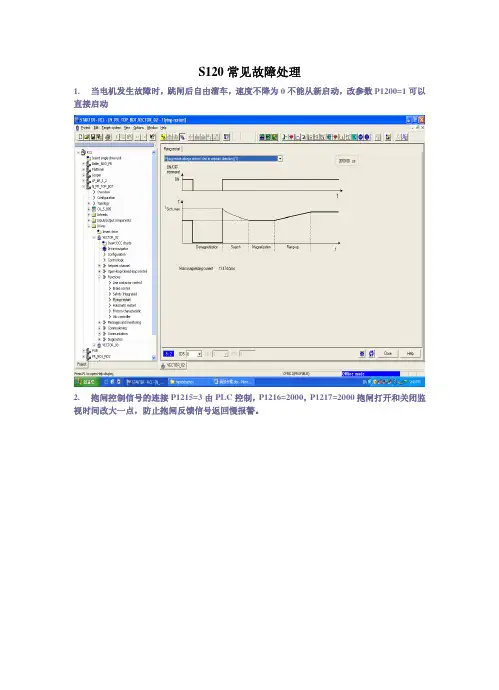
S120常见故障处理1.当电机发生故障时,跳闸后自由溜车,速度不降为0不能从新启动,改参数P1200=1可以直接启动2.抱闸控制信号的连接P1215=3由PLC控制,P1216=2000,P1217=2000抱闸打开和关闭监视时间改大一点,防止抱闸反馈信号返回慢报警。
3.报(F7900)电机锁死故障,即有速度给定值,但实际值没有增长,转矩达到限幅值。
改参数:P2175 =2.03%改到1.53% 速度设定监视极限值P2177=10s 改到15s 故障延时时间分两种情况(p1300≥20或p1300<20)p1300 < 20 (V/f open-loop control):It is not possible to select rotating measurement or speed controller optimization.p1300 = 20, 22 (sensorless operation):Only rotating measurement or speed controller optimization can be selected in the sensorless mode.p1300 = 21, 23 (operation with encoder):Both versions (sensorless and with encoder) of the rotatingmeasurement and speed controller optimization can be selected.改参数:P1082 =110%改到115% 速度限幅值或者KP增大5.报(F07902)电机堵转故障,偏差大于设定值,转矩达到限幅值,经过延时后报故障。
改参数:P1745=20%改到25% 速度设定监视极限值P2178=10s 改到15s 故障延时时间6.报(A7903)堵转报警,即速度偏差大于设定值经过延时后报故障改参数:P2163 =20%改到30% 速度设定监视极限值P2166=200ms改到400ms 故障延时时间7.急停报F01611(F01600)F30611(F30600),检查急停继电器信号是否正常,并注意端子极性,Motor Module 和Control Unit 各封锁半个桥臂,并且两个信号在相同的延时后(CuP9650,MMP9850)同时收到,不然报故障,如果信号恢复后仍然不能复位,需重新上电。
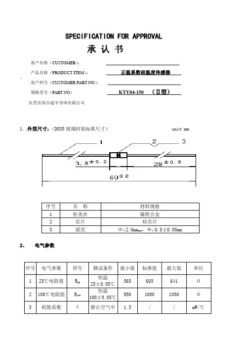
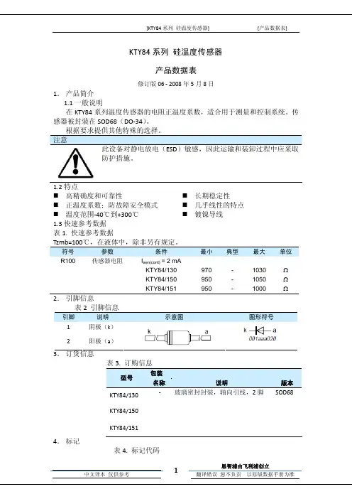
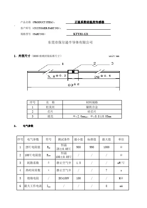
南京华巨电子有限公司Sinochip(Nanjing)Electronics Co.,LTDSKTY84‐150硅温度传感器中文资料 KTY84温度传感器中文资料产 品 规 格 书文件编号 Q/SC.G-49.07.031-2015产品名称 KTY84-150温度传感器, KTY84/150温度传感器产品代码 49007031产品型号 SKTY84-150-S2(520)版 次 A/0拟制: 王立志审核: 张建军批准: 唐成刚2015年11月27日发布 2015年11月27日实施1、产品名称、型号、代码、型号规则 (2)2、主要参数2.1产品执行标准 (2)2.2外形尺寸,结构 (2)2.3性能参数 (3)2.4温度特性曲线图 (3)2.5S Y84-150分度表 (4)3、包装 (5)1、产品名称、型号、代码、型号规则名称:硅温度传感器型号:SKTY84-150-S2(520)代码:49011027型号规则:2、主要参数2.1产品执行标准IEC601342.2外形尺寸、结构Q/SC.G-49.11.027-2015版次: A/0 共 5 页 第 3 页 2.3 性能参数序号 项目 技术要求1 常温电阻(R25℃) 603±38Ω2 100摄氏度电阻(R100℃) 1000±50Ω3 温度系数(100℃) 0.61%K4 温度范围(压接式) -40℃~210℃5 标准工作电流 2mA6 最大工作电流(环境温度25℃) 10mA(max)7 热动作时间(τ) 在静止空气中τ=20s 在静止液体中τ=1s 在流动液体中τ=0.5s(注:热动作时间τ是传感器的环境对应的阻值,要上升到某一温度的度数。
63.2%转移到环境温度所用的时间。
)2.4温度特性曲线图Q/SC.G-49.11.027-2015版次: A/0 共 5 页 第 4 页 2.5 KTY84-150分度表R-T特性参数表摄氏度华氏度KTY84-150℃℉ %/(K)(Ω)(K)MIN TYP MAX‐40 ‐40 0.84 332 359 386 ±8.85 ‐30 ‐22 0.83 362 391 419 ±8.76 ‐20 ‐4 0.82 394 424 455 ±8.70 ‐10 14 0.80 428 460 492 ±8.65 0 32 0.79 464 498 532 ±8.61 10 50 0.77 503 538 574 ±8.58 20 68 0.75 544 581 618 ±8.55 25 77 0.74 565 603 641 ±8.54 30 88 0.73 587 626 665 ±8.53 40 104 0.71 632 672 713 ±8.50 50 122 0.70 679 722 764 ±8.46 60 140 0.68 729 773 817 ±8.42 70 158 0.66 781 826 872 ±8.37 80 176 0.64 835 882 929 ±8.31 90 194 0.63 891 940 989 ±8.25 100 212 0.61 950 1000 1050 ±8.17 110 230 0.60 1007 1062 1117 ±8.66 120 248 0.58 1067 1127 1187 ±9.17 130 266 0.57 1128 1194 1259 ±9.69 140 284 0.55 1191 1262 1334 ±10.24 150 302 0.54 1256 1334 1412 ±10.80 160 320 0.53 1322 1407 1492 ±11.37 170 338 0.52 1391 1482 1574 ±11.96 180 356 0.51 1461 1560 1659 ±12.58 190 374 0.49 1533 1640 1747 ±13.20 200 392 0.48 1607 1722 1837 ±13.85 210 410 0.47 1863 1807 1931 ±14.51Q/SC.G-49.11.027-2015版次: A/0 共 5 页 第 4 页 温度特性曲线图3、包装产品放入塑料袋内,并放入质检证后塑封;包装箱内附有检验报告、送货单。
1.Product profile1.1General descriptionThe temperature sensors in the KTY84 series have a positive temperature coefficient of resistance and are suitable for use in measurement and control systems.The sensors are encapsulated in the SOD68 (DO-34) package.Other special selections are available on request.1.2Features1.3Quick reference data2.Pinning informationKTY84 seriesSilicon temperature sensorsRev. 06 — 8 May 2008Product data sheetCAUTIONThis device is sensitive to ElectroStatic Discharge (ESD). Therefore care should be taken during transport and handling.I High accuracy and reliability I Long-term stabilityI Positive temperature coefficient;fail-safe behaviorI Virtually linear characteristics I T emperature range −40°C to +300°CI Nickel plated leadsTable 1.Quick reference dataT amb =100°C; in liquid; unless otherwise specified.Symbol Parameter Conditions MinTypMaxUnitR 100sensor resistanceI sen(cont)=2mA KTY84/130970-1030ΩKTY84/150950-1050ΩKTY84/151950-1000ΩTable 2.Pinning Pin Description Simplified outline Graphic symbol1cathode (k)2anode (a)aka001aaa020k3.Ordering information4.Marking5.Limiting values[1]For temperatures greater than 200°C, a sensor current of I sen(cont)=2mA must be used.Table 3.Ordering informationType numberPackage NameDescriptionVersion KTY84/130-hermetically sealed glass package; axial leaded; 2leadsSOD68KTY84/150KTY84/151Table 4.Marking codesType numberMarking code KTY84/130KT84L KTY84/150KT84M KTY84/151KT84OTable 5.Limiting valuesIn accordance with the Absolute Maximum Rating System (IEC 60134).Symbol ParameterConditionsMinMax Unit I sen(cont)continuous sensor current in free air; T amb =25°C [1]-10mA in free air; T amb =300°C-2mA T ambambient temperature−40+300°C6.CharacteristicsTable 6.CharacteristicsT amb=100°C; in liquid; unless otherwise specified.Symbol Parameter Conditions Min Typ Max UnitR100sensor resistance I sen(cont)=2mAKTY84/130970-1030ΩKTY84/150950-1050ΩKTY84/151950-1000ΩTC temperature coefficient-0.61-%/KR250/R100resistance ratio T amb=250°C and 100°C 2.111 2.166 2.221R25/R100resistance ratio T amb=25°C and 100°C0.5950.6030.611τth thermal time constant in still air[1]-20-sin still liquid[1]-1-sin flowing liquid[1]-0.5-s[1]The thermal time constant is the time taken for the sensor to reach 63.2% of the total temperature difference. For example, if a sensorwith a temperature of 25°C is moved to an environment with an ambient temperature of 100°C, the time for the sensor to reach a temperature of 72.4°C is the thermal time constant.Table 7.Ambient temperature, corresponding resistance, temperature coefficient and maximum expected temperature error for KTY84/130 and KTY84/150I sen(cont)=2mA.Ambient temperature Temperaturecoefficient(%/K)KTY84/130KTY84/150(°C)(°F)Resistance (Ω)Temperatureerror (K)Resistance (Ω)Temperatureerror (K)Min Typ Max Min Typ Max−40−400.84340359379±6.48332359386±8.85−30−220.83370391411±6.36362391419±8.76−20−40.82403424446±6.26394424455±8.7−10140.80437460483±6.16428460492±8.65 0320.79474498522±6.0746*******±8.61 10500.77514538563±5.98503538574±8.58 20680.75555581607±5.89544581618±8.55 25770.74577603629±5.84565603641±8.54 30860.73599626652±5.79587626665±8.53 401040.71645672700±5.69632672713±8.5 501220.70694722750±5.59679722764±8.46 601400.68744773801±5.47729773817±8.42 701580.66797826855±5.34781826872±8.37 801760.64852882912±5.21835882929±8.31 901940.63910940970±5.06891940989±8.25 1002120.6197010001030±4.995010001050±8.17 1102300.60102910621096±5.31100710621117±8.66 1202480.58108911271164±5.73106711271187±9.17 1302660.57115211941235±6.17112811941259±9.69 1402840.55121612621309±6.63119112621334±10.24 1503020.54128213341385±7.1125613341412±10.8 1603200.53135014071463±7.59132214071492±11.37 1703380.52142014821544±8.1139114821574±11.96 1803560.51149215601628±8.62146115601659±12.58 1903740.49156616401714±9.15153316401747±13.2 2003920.48164117221803±9.71160717221837±13.85 2104100.47171918071894±10.28168318071931±14.51 2204280.46179818931988±10.87176018932026±15.19 2304460.45187919822085±11.47183919822125±15.88 2404640.44196220732184±12.09192020732226±16.59 2504820.44204621662286±12.73200321662329±17.32 2605000.42213222612390±13.44208722612436±18.15 2705180.41221923572496±14.44217223572543±19.36 2805360.38230424522600±15.94225524522650±21.21 2905540.34238425422700±18.26233325422751±24.14 3005720.29245626242791±22.12240426242844±29.05Table 8.Ambient temperature, corresponding resistance, temperature coefficient and maximum expected temperature error for KTY84/151I sen(cont)=2mA.Ambient temperature Temperaturecoefficient(%/K)KTY84/151(°C)(°F)Resistance (Ω)Temperatureerror (K)Min Typ Max−40−400.84332350368±5.97−30−220.83362381399±5.84−20−40.82394414433±5.72−10140.80428449469±5.62 0320.79464486507±5.51 10500.77503525547±5.41 20680.75544566589±5.31 25770.74565588611±5.25 30860.73587610633±5.2 401040.71632656679±5.08 501220.70679704728±4.96 601400.68729754778±4.83 701580.66781806831±4.68 801760.64835860885±4.53 901940.63891916942±4.37 1002120.619509751000±4.19 1102300.60100710361064±4.58 1202480.58106710991131±4.99 1302660.57112811641199±5.41 1402840.55119112311271±5.84 1503020.54125613001345±6.3 1603200.53132213721421±6.77 1703380.52139114451500±7.25 1803560.51146115211581±7.75 1903740.49153315991664±8.27 2003920.48160716791751±8.81 2104100.47168317611839±9.36 2204280.46176018461931±9.93 2304460.45183919322024±10.51 2404640.44192020212121±11.11 2504820.44200321122220±11.73 2605000.42208722052321±12.42 2705180.41217222982424±13.37 2805360.38225723912525±14.79 2905540.34233524792622±16.98 3005720.29240625582710±20.61Fig 1.Maximum expected temperature error (ΔT)Fig 2.Maximum operating current for safe operationT amb =100°CFig 3.Sensor resistance as a function of ambient temperature and operating currentFig 4.Deviation of sensor resistance as a function of operating current in still liquid30100100300mcd39920020T (K)−100−10−30T amb (°C)−20KTY84/150KTY84/150KTY84/130/151mcd401128I sen(cont)(mA)400100300200−100T amb (°C)321100200400mlc150300KTY84operating current I =2 mA 1 mA0.5 mA−1 mAR (k Ω)T amb (°C)12340mcd400302010R (Ω)−10I sen(cont) (mA)7.Package outline8.Revision historyFig 5.Minimized package outline SOD68Table 9.Revision historyDocument ID Release date Data sheet status Change notice Supersedes KTY84_SER_620080508Product data sheet-KTY84_SERIES_5Modifications:•The format of this data sheet has been redesigned to comply with the new identity guidelines of NXP Semiconductors.•Legal texts have been adapted to the new company name where appropriate.KTY84_SERIES_520030915Product specification -KTY84-1SERIES_4KTY84-1SERIES_420000825Product specification -KTY84-1SERIES_3KTY84-1SERIES_319980409Product specification -KTY84-1SERIES_2KTY84-1SERIES_219961206Product specification -KTY84-1 series KTY84-1 seriesMay 1990---97-06-09Dimensions in mm 3.04max 25.4min 25.4min 0.55max1.6max9.Legal information9.1Data sheet status[1]Please consult the most recently issued document before initiating or completing a design.[2]The term ‘short data sheet’ is explained in section “Definitions”.[3]The product status of device(s)described in this document may have changed since this document was published and may differ in case of multiple devices.The latest product status information is available on the Internet at URL .9.2DefinitionsDraft —The document is a draft version only. The content is still under internal review and subject to formal approval, which may result in modifications or additions. NXP Semiconductors does not give any representations or warranties as to the accuracy or completeness ofinformation included herein and shall have no liability for the consequences of use of such information.Short data sheet —A short data sheet is an extract from a full data sheet with the same product type number(s)and title.A short data sheet is intended for quick reference only and should not be relied upon to contain detailed and full information. For detailed and full information see the relevant full data sheet, which is available on request via the local NXP Semiconductors sales office. In case of any inconsistency or conflict with the short data sheet, the full data sheet shall prevail.9.3DisclaimersGeneral —Information in this document is believed to be accurate andreliable.However,NXP Semiconductors does not give any representations or warranties,expressed or implied,as to the accuracy or completeness of such information and shall have no liability for the consequences of use of such information.Right to make changes —NXP Semiconductors reserves the right to make changes to information published in this document, including withoutlimitation specifications and product descriptions, at any time and without notice.This document supersedes and replaces all information supplied prior to the publication hereof.Suitability for use —NXP Semiconductors products are not designed,authorized or warranted to be suitable for use in medical, military, aircraft,space or life support equipment, nor in applications where failure ormalfunction of an NXP Semiconductors product can reasonably be expected to result in personal injury, death or severe property or environmentaldamage. NXP Semiconductors accepts no liability for inclusion and/or use of NXP Semiconductors products in such equipment or applications and therefore such inclusion and/or use is at the customer’s own risk.Applications —Applications that are described herein for any of these products are for illustrative purposes only. NXP Semiconductors makes no representation or warranty that such applications will be suitable for the specified use without further testing or modification.Limiting values —Stress above one or more limiting values (as defined in the Absolute Maximum Ratings System of IEC 60134)may cause permanent damage to the device.Limiting values are stress ratings only and operation of the device at these or any other conditions above those given in theCharacteristics sections of this document is not implied. Exposure to limiting values for extended periods may affect device reliability.Terms and conditions of sale —NXP Semiconductors products are sold subject to the general terms and conditions of commercial sale,as published at /profile/terms , including those pertaining to warranty,intellectual property rights infringement and limitation of liability, unless explicitly otherwise agreed to in writing by NXP Semiconductors. In case of any inconsistency or conflict between information in this document and such terms and conditions, the latter will prevail.No offer to sell or license —Nothing in this document may be interpreted or construed as an offer to sell products that is open for acceptance or the grant,conveyance or implication of any license under any copyrights,patents or other industrial or intellectual property rights.Quick reference data —The Quick reference data is an extract of theproduct data given in the Limiting values and Characteristics sections of this document, and as such is not complete, exhaustive or legally binding.9.4TrademarksNotice:All referenced brands,product names,service names and trademarks are the property of their respective owners.10.Contact informationFor more information, please visit:For sales office addresses, please send an email to:salesaddresses@Document status [1][2]Product status [3]DefinitionObjective [short] data sheet Development This document contains data from the objective specification for product development.Preliminary [short] data sheet Qualification This document contains data from the preliminary specification.Product [short] data sheetProductionThis document contains the product specification.11.Contents1Product profile. . . . . . . . . . . . . . . . . . . . . . . . . . 11.1General description. . . . . . . . . . . . . . . . . . . . . . 11.2Features . . . . . . . . . . . . . . . . . . . . . . . . . . . . . . 11.3Quick reference data. . . . . . . . . . . . . . . . . . . . . 12Pinning information. . . . . . . . . . . . . . . . . . . . . . 13Ordering information. . . . . . . . . . . . . . . . . . . . . 24Marking. . . . . . . . . . . . . . . . . . . . . . . . . . . . . . . . 25Limiting values. . . . . . . . . . . . . . . . . . . . . . . . . . 26Characteristics. . . . . . . . . . . . . . . . . . . . . . . . . . 37Package outline . . . . . . . . . . . . . . . . . . . . . . . . . 78Revision history. . . . . . . . . . . . . . . . . . . . . . . . . 79Legal information. . . . . . . . . . . . . . . . . . . . . . . . 89.1Data sheet status . . . . . . . . . . . . . . . . . . . . . . . 89.2Definitions. . . . . . . . . . . . . . . . . . . . . . . . . . . . . 89.3Disclaimers. . . . . . . . . . . . . . . . . . . . . . . . . . . . 89.4Trademarks. . . . . . . . . . . . . . . . . . . . . . . . . . . . 810Contact information. . . . . . . . . . . . . . . . . . . . . . 811Contents. . . . . . . . . . . . . . . . . . . . . . . . . . . . . . . 9Please be aware that important notices concerning this document and the product(s)described herein, have been included in section ‘Legal information’.© NXP B.V.2008.All rights reserved.For more information, please visit: For sales office addresses, please send an email to: salesaddresses@。
南京华巨电子有限公司
Sinochip(Nanjing)Electronics Co.,LTD
产 品 规 格 书
文件编号 Q/SC.G-49.02.029-2015
产品名称 KTY84-150温度传感器, KTY84/150温度传感器产品代码 49002029
产品型号 SKTY84-150-S2(520)
版 次 A/0
拟制: 王立志
审核: 张建军
批准: 唐成刚
2015年07月31日发布 2015年07月31日实施
1、产品名称、型号、代码、型号规则 (2)
2、主要参数
2.1产品执行标准 (2)
2.2外形尺寸,结构 (2)
2.3性能参数 (3)
2.4温度特性曲线图 (3)
2.5S Y84-150分度表 (4)
3、包装 (5)
1、产品名称、型号、代码、型号规则
名称:硅温度传感器
型号:KTY84-130-S2(520)
代码:49002031
型号规则:
2、主要参数
2.1产品执行标准
IEC60134
2.2外形尺寸、结构
Q/SC.G-49.02.029-2015版次: A/0 共 5 页 第 3 页 2.3 性能参数
序号 项目 技术要求
1 常温电阻(R25℃) 603±38Ω
2 100摄氏度电阻(R100℃) 1000±50Ω
3 温度系数(100℃) 0.61%K
4 温度范围(压接式) -40℃~210℃
5 标准工作电流 2mA
6 最大工作电流(环境温度25℃) 10mA(max)
7 热动作时间(τ) 在静止空气中τ=20s 在静止液体中τ=1s 在流动液体中τ=0.5s
(注:热动作时间τ是传感器的环境对应的阻值,要上升到某一温度的度数。
63.2%转移到环境温度所用的时间。
)
2.4温度特性曲线图
Q/SC.G-49.02.029-2015版次: A/0 共 5 页 第 4 页 2.5 KTY84-150分度表
R-T特性参数表
摄氏度华氏度KTY84-150
℃℉ %/(K)
(Ω)
(K)MIN TYP MAX
‐40 ‐40 0.84 332 359 386 ±8.85 ‐30 ‐22 0.83 362 391 419 ±8.76 ‐20 ‐4 0.82 394 424 455 ±8.70 ‐10 14 0.80 428 460 492 ±8.65 0 32 0.79 464 498 532 ±8.61 10 50 0.77 503 538 574 ±8.58 20 68 0.75 544 581 618 ±8.55 25 77 0.74 565 603 641 ±8.54 30 88 0.73 587 626 665 ±8.53 40 104 0.71 632 672 713 ±8.50 50 122 0.70 679 722 764 ±8.46 60 140 0.68 729 773 817 ±8.42 70 158 0.66 781 826 872 ±8.37 80 176 0.64 835 882 929 ±8.31 90 194 0.63 891 940 989 ±8.25 100 212 0.61 950 1000 1050 ±8.17 110 230 0.60 1007 1062 1117 ±8.66 120 248 0.58 1067 1127 1187 ±9.17 130 266 0.57 1128 1194 1259 ±9.69 140 284 0.55 1191 1262 1334 ±10.24 150 302 0.54 1256 1334 1412 ±10.80 160 320 0.53 1322 1407 1492 ±11.37 170 338 0.52 1391 1482 1574 ±11.96 180 356 0.51 1461 1560 1659 ±12.58 190 374 0.49 1533 1640 1747 ±13.20 200 392 0.48 1607 1722 1837 ±13.85 210 410 0.47 1863 1807 1931 ±14.51
Q/SC.G-49.02.029-2015版次: A/0 共 5 页 第 4 页 3、包装
产品放入塑料袋内,并放入质检证后塑封;
包装箱内附有检验报告、送货单。
其中包含下列项目:
a)公司商标、名称
b)生产批号
c)产品代码
d)数量
e)生产日期。