Dresser Consolidated Safety Valve Instruction
- 格式:ppt
- 大小:17.52 MB
- 文档页数:123
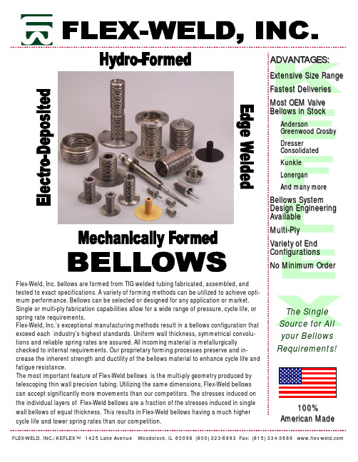
100% American MadeA DVANTAGES :Extensive Size Range Fastest Deliveries Most OEM Valve Bellows in StockAndersonGreenwood Crosby Dresser Consolidated Kunkle Lonergan And many moreBellows System Design Engineering Available Multi -Ply Variety of End Configurations No Minimum Order FLEX-WELD, INC./KEFLEX TM1425 Lake Avenue Woodstock, IL 60098 (800) 323-6893 Fax: (815) 334-3689 Flex-Weld, Inc. bellows are formed from TIG welded tubing fabricated, assembled, and tested to exact specifications. A variety of forming methods can be utilized to achieve opti-mum performance. Bellows can be selected or designed for any application or market. Single or multi-ply fabrication capabilities allow for a wide range of pressure, cycle life, or spring rate requirements.Flex-Weld, Inc.’s exceptional manufacturing methods result in a bellows configuration that exceed each industry’s highest standards. Uniform wall thickness, symmetrical convolu-tions and reliable spring rates are assured. All incoming material is metallurgically checked to internal requirements. Our proprietary forming processes preserve and in-crease the inherent strength and ductility of the bellows material to enhance cycle life and fatigue resistance.The most important feature of Flex-Weld bellows is the multi-ply geometry produced by telescoping thin wall precision tubing. Utilizing the same dimensions, Flex-Weld bellows can accept significantly more movements than our competitors. The stresses induced on the individual layers of Flex-Weld bellows are a fraction of the stresses induced in single wall bellows of equal thickness. This results in Flex-Weld bellows having a much highercycle life and lower spring rates than our competition.The Single Source for All your BellowsRequirements!AVAILABLE MATERIALSTOLL FREE: 1-800-323-6893Military Cryogenic UHV NuclearNational Labs ValveT-321 Stainless Steel T-316 (L) Stainless Steel T-304 (L) Stainless Steel T-347 Stainless Steel BrassBeryllium Copper Phosphor BronzeCarpenter Alloy 20Inconel 625 Inconel 625 LCF Monel 400Hastelloy C-276, C-22, C-2000Haynes 230 Hastelloy B, B2 TitaniumOther alloys available upon requestTYPICAL APPLICATIONSExpansion Joint AccumulatorElectrode or Shaft SealingMechanical SealingRotary Seal Housing Air Pressure Control Pressure DetectorRemote Transmission& Flow ControlMARKETSValve Repair Steel PaperEngine/ Exhaust Petrochemical PharmaceuticalPower Generation Commercial Instrumentation Vacuum Process ElectronicAutomotive Aerospace Medical Industrial HVACSemiconductorLOWER THRUST FORCES - The multi-ply design results in lower spring rates. Also, the effective cross sectional area of multi-ply bellows is less, compared to single-ply bellows, to accommodate a given movement. These two reduc-tions result in lower forces and moments on the anchors, equipment and guides. A side benefit is that less anchors and guides will be required in the overall bellows piping system.FLEX -WELD FEATURES:ADVANTAGES:Increased flexibility Higher pressures attainable Lower thrust forcesMinimal installation length required Fail safe designElevated corrosion resistanceMULTI-PLY SAFETY FACTORS - In a critical application, a multi-ply bellows assembly can in most cases preclude a catastrophic failure. If a failure occurs in one ply due to corrosion or fatigue, the intact plies will work as a protective barrier to contain the pressure and the medium until a replace-ment can be made. Flex-Weld Multi-ply bellows are designed to provide utmost safety in the event of system failure. The burst pressures are a multiplier of the operating pressure making the Flex-Weld multi-ply bel-lows the most reliable component in the system.CYCLE LIFE OPTIMIZATION - The technical advantage of using multiple plies of .002” - .006” wall thickness material is that less residual stresses are intro-duced at the time of bellows forming. Overall, Flex-Weld multi-ply bellows have lower built-in and induced stresses which ultimately results in longer cycle life. Also, the thinner gauge multiple plies have less localized induced stresses dur-ing operation compared to a single thicker ply. The configuration of the convo-lutions (pitch, depth, contour, number of plies, ply thickness) of FLEX-WELD multi-ply bellows are optimized to offer the highest fatigue life.COMPACT DESIGN - Multi-ply bellows have more flexibility than conventional sin-gle-ply bellows and thus require less live length to accommodate a given move-ment. The live length of the bellows can be minimized to absorb a given combi-nation of axial, lateral and angular movements. This results in an economical compact assembly which can be installed in a minimal amount of space. An ad-ditional benefit is a small effective area resulting in lower thrust pressures onthe anchors and mechanical equipment in the system.Proprietary forming techniques produce metallic bellows of consistent quality and close tolerances.In-process testing & inspection result in the most reliable bellows.Mechanically forming one convolution at a time minimizes material thinning. High frequency pulse TIG welds minimize the heat –affected (HAZ) zone and re-sults in superior bellows strength, ductility and dependability. Diameters ranging from 1/8” I.D. to 280" I.D.Pressures ranging from vacuum to 10,000 PSI depending on application. Temperatures ranging from cryogenic to 2800°F Axial movements up to 24" depending up on size.Material handling from abrasive solids to corrosive gases and liquids.TOLL FREE: 1-800-323-6893MANUFACTURING CAPABILITIESSPECIAL CAPABILITIESMass Spec Leak Testing Teflon Coating Heat TreatingLiquid Penetrant Testing / Radiography PlatingCustom Flange Fitting Design Machining / Stamping WeldingLaser, Lap, ASME, MIG, TIG, RSEW Soldering BrazingMaterial SelectionThe selection of economical and proper end fittings is vital to goodbellows design. Flex-Weld, Inc. offers a wide range of configurationsincluding; straight, slotted, flared, flanged, grooved and fitted ends.These fittings permit wide latitude in valve and instrument design.Flex-Weld, Inc. bellows engineers routinely are asked to analyze andreview the entire scope of intended use to quickly and accuratelyinsure overall system performance. Our reputation is based on ourinnovative designs, fast turn-around, and extensive customized endfittings so often demanded by progressive industries.END CONFIGURATIONSADBACTIVE CONV.ONE FULLCONVOLUTIONCBELLOWSO.D. BELLOWS DESIGN DATAStandard Bellows Neck Cuff NeckCup Neck Open ConvolutionFlat Faced Closed ConvolutionDATA WORKSHEET FOR BELLOWS DESIGN RECOMMENDATIONSSubmitted By: Company:Part Description: Quantity Required:Size of Assembly:Nom. Size or inside diameter of the connecting end fittingsInchesInstalled Length (OAL):Space between connecting pointsInchesType of Media:indicate if liquid, steam, gas, exhaust, slurry, solids, etc.Bellows Material Type:Temperature of Flowing Media:Indicate both operating and maximum temperatures of systemOperating °F Maximum °FTemperature of Surrounding Atmosphere:indicate both min. and max. temp of atmosphere at the expansion jointMin. Degrees °F Max. Degrees °FVelocity of Flowing Media:In feet/sec or gallons/minFeet/Sec Gal/MinOperating Pressure:Actual pressure which system works under normal conditionsPositive PSIG Negative HGDesign Pressure of System:Highest / most severe pressure during operationPositive PSIG Negative HGTest Method and Requirements:Test method used and testing levels required for systemPositive PSIG Negative HGAxial Movement (Compression/Extension):In inches as a result of system extension/expansionCompression in Inches Extension in Inches Lateral Deflection / Offset: In inches: InchesAngular Movement: In degrees:Lead Time / Target Pricing: Lead Time Target PriceEnd Fittings 1/E: Indicate end fitting requirements, thickness, material type, & configurationEnd Fittings O/E: Indicate end fitting requirements, thickness, material type, & configurationSpecial Notes:DegreesAdditional Literature:FLEX-WELD, INC./KEFLEX TM 1425 Lake Avenue Woodstock, IL 60098 (800) 323-6893 Fax: (815) 334-3689 Edge Welded Bellows 10MC / 30MC Exhaust Bellows Series Fabricated Metal Hose。

1 (6)P r i n t e d i n G e r m a n y • E d i t i o n 11.18 • N r . 214 756Single-stage safety solenoid valves MV/4MVD, MVD/5, MVDLE/56.20T echnical descriptionThe DUNGS safety solenoid valve MV/4, MVD, MVD/5, MVDLE/5 is a single-stage automatic shut-off valve as per EN 161 for gas burners and gas appliance.- Max. operating pressure up to 200, 360 or 500 mbar (20, 36 or 50 kPa)- normally closed- MV , MVD: fast opening- MVDLE: Slow opening with adjustable fast stroke for start gas volume- Main volume adjustable (MVD/MVDLE)- DC solenoid, rectifier wiring with radio interference suppression in terminal box with PG screw union- Mountable closed position signal contact to monitor closed position of valve (.../5)- Pipe thread as per ISO 7/1- Flange connection as per DIN EN 1092-1- Reliable function, rugged and mainte-nance-free- On request, design without non-ferrous metalsApplicationThe solenoid valve is used for securing, limit-ing, shutting off and releasing gas supply to gas burners and gas appliances.MV/4 Range of application: for large break -ing capacities, e.g. pulsed firing.The DUNGS safety solenoid valve MV ... is suitable for gases of families 1, 2, 3 and other neutral gaseous media.ApprovalEC type testing certificate as per: • EC-Gas Appliances Regulation • EC-Pressure Equipment DirectiveApprovals in other important gas consum -ing countries.Special designs for the North American market with U L, FM and CSA registrations.2 (6)10 15 20 25 40 50 65 80 100 125 1503/8 1/2 3/4 1 1 1/2 2 2 1/2Connection flange (PN 16) as per DIN EN 1092-1up to 200 mbar (20 kPa), 360 mbar (36 kPa) or up to 500 mbar (50 kPa) - refer to type overviewValve as per EN 161, Class A, Group 2, single-stage mode < 1 s< 1 s for MVDLE approx. 20 s at room temperature 20 °C and without fast stroke AdjustableManually adjustable on MVD and MVDLE Housing: aluminium, steel, brass Seals:NBR basis230 V AC (+10 % -15 %); 50-60 Hz - other voltages on request Solenoids 60E, 61E in 24-28 VDCexternal activation of solenoid coils required, see operating and mounting instructions Refer to type overview 100 %IP 54, IP 65 on requestAt screw terminals via PG* 11 cable gland (* = heavy-gauge conduit thread)Plug connection as per DIN 175 0301-803 can be retrofittedMV/4, MVD…/5: max. 1000/h MVDLE…/5: max. 100/hMVD 2125/5, MVD 2150/5, MVD 5100/5, MVD 5125/5, MVD 5150/5: max. 20/h MV 5125/5 S, MV 5150/5 S: max. 20/hG 1/4 ISO 118, on both sides in inlet section,additionally G 3/4 on input side, form size DN 40 (flange) upwards Sieve installed, mesh width 1 mm -15 °C to +60 °CSolenoid from vertically upright to horizontally lyingMV/5, MVD/5, MVDLE/5: Type K01/1, DIN-tested, mountable on DN 10 - DN 150T ype VDK 200 A S02, mountable via G 1/4 test connection, T ype VPS 504, mountable with adapter up to DN 80K01 closed position signal contact, see Datasheet 12.01 211 202Equipment plug for line socket, DIN 175301-803215 733SpecificationsNominal diametersPipe thread as per ISO 7/1, Rp FlangeMax. operating pressure Solenoid valve Closing time Opening time Fast strokeMain volume adjustment Materials of gas-conveying parts Voltage/frequencyRating / power consumption Switch-on duration Degree of protection Electrical connection Switching rateMeasuring/ignition gas connection Dirt trapAmbient temperature Installation positionClosed position signal contact Valve proving system Accessoriesd = largest width1)Solenoids 60E, 61E in 24-28 VDCexternal activation of solenoid coils required, see operating and mounting instructions2)= for max. 3 s* = PG 11** = Line socket, black3 (6)4 (6)** Switch-on current for approx. 3 sDimensions [mm]DN / Rp P max. [VA]* Weight [kg]Opening time f e c a d bg I max.~(AC) 230 V [A] **Typep max.OrderNo.Sole-noid No. h 1)external activation of solenoid coils required, see operating and mounting instructions5 (6)GasartT ype of gas T ype de gaz Tipo di gasErdgas/Nat.Gas/Gaz naturel/Gas metano Stadtgas/City gas/Gaz de ville/Gas cittàFlüssiggas/LPG/Gaz liquide/Gas liquido Luft/Air/Air/AriaDichte Spec. Wgt.poids spécifique Peso specifico[kg/m 3]0.810.582.081.24dv 0.650.471.671.00f1.241.460.771.00Dichte LuftSpec. weight airpoids spécifique de l´air peso specifico ariaDichte des verwendeten Gases Spec. weight of gas usedpoids spécifique du gaz utilisépeso specifico del gas utilizzatof =V verwendetes Gas/gas used/ gaz utilisé/gas utilizzato= V Luft/air/air/aria x f °Functional descriptionThe DUNGS safety solenoid valve is an automatic shut-off valve operated with auxiliary power.The electromagnetic drive opens against the force of the closing spring 4.If the auxiliary power is interrupted (operating voltage), closing spring 4 closes the valve within 1 second.The closed position of the valve can be monitored by a mountable closed position signal contact.The stroke of armature 5 can be limited by the setting screw 8.The hydraulic brake 10 permits slow opening. Fast stroke 9 can be ad -justed.°6 (6)We reserve the right to make any changes in the interest of technical progress.Single-stage safety solenoid valves MV/4MVD, MVD/5,MVDLE/5Head Offices and Factory Karl-Dungs-Platz 1D-73660 Urbach, Germany T elephone +49 (0)7181-804-0Fax +49 (0)7181-804-166Postal addressKarl Dungs GmbH & Co. KG Postfach 12 29D-73602 Schorndorf, Germany ********************Internet 。

Refrigeration Control Valves Safety Bulletin RSBCV Safety ProceduresIntroductionThis bulletin is a summary of safety procedures for the proper selection, installation, use and maintenance of Refrigerating Specialties Division industrial refrigerant control valves. Additional free copies are available and should be distributed to all concerned personnel. This bulletin is intended to help you protect your personnel, product and plant. Because of space imitations, this bulletin must be supplemented by accepted and known industry safety practices and local code requirements. Refrigerating Specialties Division control valvesare designed and built to the highest standardsof the refrigeration industry. However, for proper performance the valves must be correctly chosen, properly installed and periodically serviced. Because safe operation is of primary concern, this bulletin emphasizes suggestions for the safe installation and maintenance of Refrigerating Specialties Valves. Read this information carefully before installing a valve or working on one already installed; also, use it to review all previous installations.All personnel working on valves must be qualified to work on refrigeration systems. Any person intendingto service a valve should completely read this bulletin and the product bulletin describing the particular valve and its operation before any work begins. If there are any questions, contact Refrigerating Specialties before proceeding with the work.Receiving and UnpackingAll control valves are packed for maximum protection. Unpack carefully. Flange bolts are packed in cotton bags and coils are packed loose. Check the carton to make sure all flanges and other items are unpacked and in agreement with the packing slip. Save the enclosed instructions for the installer and eventual user. Do not remove the protective covering from the inlet and outlet of the control valve until the valve is ready to be installed.Caution: Do not, at any time, make any alteration or modifications to any Refrigerating Specialties Division valves or regulators without the express and written approval of this company. Threaded parts should not be subjected to excessive torque by use of an oversized wrench, wrench extension or by impacting the wrench handle. Where specified in the individual bulletin, observe the torque requirements for bolts, screws and other threaded parts. Contact the factory for torque values not furnished in current literature.For extensive repairs on valves or regulators, especially those more than three years old, the valves or regulators should be returned to the factory for thorough inspection and rebuilding. Spare parts should be checked for corrosion before installation. In addition, part numbers should be checked againstthe latest assembly bulletin to be sure current parts arebeing used.If a valve or regulator has failed under circumstanceswhich caused, or could have caused, injury topersonnel or damage to property, a replacementvalve should not be installed until the reason for theprevious failure is determined and corrected. Adequateprotection should be taken to prevent both liquid shockand suction shock both upstream and downstream ofthe valve or regulator.Liquid ExpansionIn liquid lines, or lines that might contain substantialamounts of liquid refrigerant, certain precautions mustbe taken to avoid damage due to liquid expansionwhen a section of line is isolated by positive shutoff valves. This condition may occur whenever theambient temperature could be higher than the liquidtemperature. This could even occur in a refrigerant oroil line other than a “liquid” line.Temperature increase in a section with trappedliquid can cause extremely high pressures due to theexpanding liquid and possibly rupture a gasket, pipe,or valve. When low temperature liquid lines are used,as in a liquid overfeed (recirculation) system, andthe lines or control valves may be exposed to warmambient conditions, particular care must be taken;liquid expansion can occur very rapidly.Check ValvesCheck valves must never be installed at the inlet ofeither a solenoid valve, a regulator or a regulator withan electric solenoid pilot shut-off feature. Also, thecheck valve should not be installed at the inlet of anoutlet pressure regulator in a system where liquid maybe trapped between the two valves. If a check valve isneeded, install it on the outlet side of such valves. Mostsolenoid valves and regulators will permit reverse flowif the outlet pressure is greater than inlet pressure. If atany time, such reverse pressure conditions are possibleand reverse flow is unacceptable a check valve shouldbe installed at the control valve outlet.All hand valves that could trap liquid when closed mustbe marked with a warning against accidental closing.The liquid refrigerant must be removed before the handvalves are closed on both sides of a control valve or anyother component. Also, liquid must be removed beforea hand valve is closed at the inlet of a solenoid valveor a regulator with positive electric shut-off, or someoutlet pressure regulators, or at the outlet of a checkvalve, unless these valves are manually open.Caution: To protect personnel, product and plant,remove all liquid from the section to be isolated beforehand valves are closed. Make sure the control valvesare open when removing the liquid. See Service andMaintenance Instructions before attempting to takeany valve apart.Relief DevicesRelief devices or relief methods should be used in allparts of a refrigeration system where liquid can betrapped and liquid expansion could take place. Underno circumstances should R/S Pressure Regulators beused as a relief to the atmosphere, R/S Type H SafetyRelief valves should be used instead.Selection and ApplicationA control valve must be selected only by a personhaving adequate knowledge of the system and ofthe valve to be chosen. Any Refrigerating SpecialtiesDivision control valve must be used only as specificallystated in Refrigerating Specialties Division Catalogsor Bulletins for normal refrigeration applicationsunless otherwise approved in writing by RefrigeratingSpecialties Division.The valves are designed to operate with ammoniaand/or halocarbon refrigerants. Valves using flangeswith copper connections must not be used withammonia refrigerant. Unless authorized by the factory,Refrigerating Specialties valves should not be used forrefrigerants or fluids not mentioned on the nameplateor in the pertinent bulletin.InstallationInstallation must be done according to all applicableSafety Codes and Standards, and by personnelqualified to install refrigeration systems. RefrigeratingSpecialties Division control valves must be installedaccording to the manufacturer’s instructions, thisbulletin, and the generally known safety practices.MountingASTM A307 Grade A square headed bolts should beused to mount flanged body valves. They assure themaximum bolt surface and flange engagement. For alllug mounted valves, flange bolts should be inserted ina direction pointing toward the valve body. The boltshould pass first through the mounting flange beforeengaging the valve flange. Allow proper space forinstalling the valve. Do not use the valve to “stretch”or “align” the pipe. Using flange bolts to close a largegap can distort the valve or at least stress it unduly, andpossibly cause it to malfunction, or the bolts may bedamaged or stripped.Verify that piping into which a valve or flange is tobe installed is properly supported and aligned. Becertain that the mating surfaces of the gasketedjoints are parallel, aligned and perpendicular to thepipe axis, in good condition and free of debris andcorrosion. Use only undamaged gaskets suitable forservice in an ammonia refrigerating system. Verifythat all the nuts, bolts, cap screws and washers meetParker’s requirements for the application and tightenprogressively in a diametrically staggered pattern.Leak test upon completing the installation. For moreinformation please reference the IIAR 2-2008 Section10.When mounting weld-end valves: welding proceduresfor all steel pipe and fitting need to conform to allrequirements of the ASME IX and other PressurePipe welding standards. In all cases where valves areinstalled without disassembly, they should be manuallyopened.LocationValves must not be installed in locations wherethey can be damaged by material handling or otherequipment. Control valves should be installed such© 2012 Parker Hannifin CorporationParker Hannifin CorporationRefrigerating Specialties Division 2445 South 25th. Avenue Broadview, IL 60155-3891phone (708) 681-6300 fax (708) 681-6306/refspecPage 2 / Safety Bulletin RSBCV050006 D 08/15/12that the inlet pipe is straight for a minimum of 6 pipe diameters. Trapped ice build-up must be avoided at or between valves and other equipment. Provide reasonable access to all control valves for maintenance purposes.InsulationWhen it is necessary to insulate the control valves, the insulation must be applied to allow access for proper operation and maintenance of the valves. The manual opening and adjusting stems should be easily accessible at all times. In the case of solenoid valves the insulation must not extend to the coil housing or coil burnout may occur. Insulation should be constructed so that sections can be easily removed and replaced to allow the valve to be disassembled. Insulation applied to strainers should provide ready access for cleaning the strainer basket.Since most maintenance problems caused by dirtoccur at the start-up of a system, it is advisable to delay insulating the control valves and strainers until the system has operated for several days. During that time the strainers should be checked for dirt and cleaned as necessary. Cotton bags are available for 25mm-100mm (1” - 4”) Type RSF Strainers to improve their ability to remove small particles of dirt during start-up.Pump Out MeansIndividual valves or control stations should be provided with means for pumping out or safely purging the refrigerant.Pressure TestingEvery segment of a refrigeration system, including control valves, should be field pressure tested before system is insulated and put in use. Make sure that correct high and low side test pressures are used. Use proper refrigerant or gas for pressure testing; that is do not use halocarbons or CO 2 to test an ammonia system, nor use ammonia to test halocarbon system. Never use the compressor in a system to build up pressure for testing.In pressure testing Range V , VA, A, B or D pressure regulators, test pressure in excess of 21. kg/cm 2 (300 psig) may cause setting shift and diaphragm may deform enough to require replacement after the test. If the above conditions exist, contact the factory for proper solution.ElectricalOnly properly qualified electricians should handle the electrical portions of control valves and their circuitry. All power supplies and wiring must be adequate to provide the proper voltage and current to the solenoid coils. The power supply must be capable of providing the proper in-rush current. Never energize the solenoid with the coil housing or plunger assembly removed.Before working on any valve be sure the circuits are completely de-energized; just throwing a switch may not be sufficient. Failure to do this may result in personal injury or damage to solenoid coils or other components. Take care to see that the circuits cannot be energized accidentally. Never energize the solenoid with the coil housing or plunger assembly removed.Service and MaintenanceAll systems require maintenance and service. The personnel doing the work must be qualified andcompletely familiar with the system they are to work on or all other precautions will be meaningless.Pump OutFor the protection of personnel, product, and plant, all refrigerant possible must be removed from a valve or any other component of the system, before any refrigerant retaining part is loosened. Before opening a valve, make sure all refrigerant liquid has been removed. In particular, beware of strainers and other sections of piping which may trap liquid refrigerant which will require a considerable length of time to remove. Pump out as much refrigerant as possible before discharging remaining refrigerant in a properly protected manner. During pump out make sure control valves are opened manually to avoidtrapping refrigerant. All type RSF and RSW Strainers are provided with 3/8” FPT connection to assist in pump out.At times it may be necessary to discharge some small amount of refrigerant from the isolated section. When this becomes necessary, certain precautions must be observed. Make sure control of discharge rate can be easily maintained and that a quick shut-off is available. Refrigerant should be discharged into and disposed of in a proper container accepted by applicable safety codes and standards. Discharge of refrigerant to atmosphere should be avoided. Never discharge any refrigerant into an area without sufficient ventilation, or into an area where open flame or electrical spark is present. Any oil in the refrigerant may cause a mist that could cause a fire or explosion. Halocarbon refrigerant should not be discharged into areas where open flame is present, since toxic gases may form. Ammonia should not be discharged into occupied areas, or areas containing product affected by ammonia. In the case of ammonia, discharge any vapor left into a container of cold water, making sure that the discharge hose remains submerged at all times. (Be sure that no pressure reversals can occur that may pull water into the system.) Water may have to be refreshed to absorb all the ammonia; about one gallon of fresh water is needed for one pound of ammonia. To prevent pulling excessive air and moisture into a system, avoid opening the system when it is under vacuum.Caution: Do not attempt to work on any part of a refrigeration system without having help nearby and observing. Use safety glasses or a safety face shield for added safety to protect the eyes. Protective equipment should be readily available and all personnel involved should be thoroughly trained in its use. Personnel should be especially protected against falling because they may be startled by escaping refrigerant. Always make sure that there is a way out and that everyone can leave the area fast. When seal caps cover manual opening or adjusting stems, the caps must beremoved with caution because liquid refrigerant could accumulate under such a cap. Avoid contact with any liquid refrigerant.DisassemblyBe sure that any person working on a valve is familiar with its construction and operation by referring to theproper bulletin. Make sure the pressure in the system to be opened is reduced to, and remains, at atmospheric pressure before valve pressure containment seals are released. A pressure gauge should be connected to the part of the system to be evacuated. Before removing the bonnet of pressure regulators, back out adjusting stem to prevent damage to the diaphragm.Re-assemblyBe sure all parts are clean and free of moisture before reassembly. Damaged parts and gaskets should be replaced. It is advisable to purge the section of air before opening it to the rest of the system. Whenopening hand valves, ensure that initial refrigerant flow will be in the normal direction of valve flow; this will avoid backflow and possible damage to the strainer if one is used.Dirt, Contamination, and CorrosionProtect the valves from foreign material during storage and installation. The protective plugs on the valve openings should remain in place until the valves are ready to be installed. Once a section of a system is installed, and before it is put into operation, it is advisable to charge it with appropriate refrigerant or suitable inert gas to avoid corrosion. Avoid exposure of R/S valves to halogenated solvents or similar reactive fluids. External corrosion over a long period of time must be controlled by painting and replacement of corroded parts.Strainer MaintenanceStrainer inspection is of utmost importance, especially the first few hours, days or weeks after the start-up. Foreign material should be removed and the screens should be washed with proper solvent. Strainer inspection and cleaning should be continued until dirt accumulation ceases. Later, any time a valve pressure containment seal is released for service or maintenance, its companion strainer should also be inspected and cleaned. Filter bags are available for 25mm-100mm (I” - 4”) Type RSF Strainers to improve their ability to remove small particles of dirt during start-up. If a strainer filter bag is used in the strainer basket, the cloth bag must be checked every few days depending upon the amount of system dirt collected. When the cloth bag no longer collects dirt, it must be discarded.General SpecificationsRefrigerating Specialties refrigerant containing valves and strainers are designed for a maximum rated pressure of 27.6 bar (400 psig) except where shown otherwise on the nameplate. They are suitable for use under most temperature conditions encountered in refrigeration systems. Maximum and minimum fluid temperatures for each valve are published in Industrial Refrigerating Control Valve Catalog C12. If either fluid or ambient temperature is below a valves rated minimum, consult the factory. In addition, should fluid temperature exceed the rated maximum or should ambient temperatures exceed 125° F ., consult thefactory.StandardEncapsulated Coil Inrush Current Holding current Fuse Size Encapsulated Coil Electrical Table。
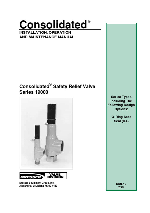
ConsolidatedINSTALLATION, OPERATIONAND MAINTENANCE MANUALConsolidated Safety Relief Valve Series 19000®®Dresser Equipment Group, Inc.Alexandria, Louisiana 71309-14301.DANGER — Immediate hazards which WILL result in severe personal injury or death.2.WARNING — Hazards or unsafe practices which COULD result in severe personal injury or death. 3.CAUTION — Hazards or unsafe practices which COULD result in minor personal injury.4.ATTENTION — Hazards or unsafe practices which COULD result in product or property damage.Product Safety Sign and Label SystemIf and when required, appropriate safety labels have been included in the rectangular margin blocks throughout this manual. Safety labels are vertically oriented rectangles as shown in the representative examples (below), consisting of three panels encircled by a narrow border. The panels can contain four messages which communicate:•The level of hazard seriousness.•The nature of the hazard.•The consequence of human or product interaction with the hazard.•The instructions, if necessary, on how to avoid the hazard.The top panel of the format contains a signal word (DANGER, WARNING, CAUTION or ATTENTION) which communicates the level of hazard seriousness. The center panel contains a pictorial which communicates the nature of the hazard, and the possible consequence of human or product interaction with the hazard. In some instances of human hazards the pictorial may, instead, depict what preventive measures to take, such as wearing protective equipment. The bottom panel may contain an instruction message on how to avoid the hazard. In the case of human hazard, this message may also contain a more precise definition of the hazard, and the consequences of human interaction with the hazard, then can be communicated by the pictorial.Do not drop or strikevalve.Wear necessaryCON-16 CON-6Page 1 ContentsI.Safety Notice (2)II.Safety Precautions and Warranty Information (3)III.Introduction (4)IV.Terminology for Safety Relief Valves (4)V.Design Features and Nomenclature (6)A.Design Features (6)B.Nomenclature (7)VI.Handling, Storage and Pre-Installation (12)A.Handling (12)B.Storage (12)C. Pre-Installation (12)VII.Recommended Installation Practices (13)A.Mounting Position (13)B.Inlet Piping (13)C.Outlet Piping (15)VIII.Disassembly Instructions (16)A.General Information (16)B.Metal Seat Valves (MS) (16)C.O-ring Seat Seal Valves (DA) (17)IX.Cleaning (17)X.Parts Inspection (17)A.Base (17)B.Metal Seat (MS) Disc (18)C."O" Ring Seat Seal (DA) Assembly (18)D.Bonnet (18)E.Metal Seat (MS) Disc Holder (18)F.O-ring (DA) Disc Holder (18)G.Guide (18)H.Spindle (18)I.Spring (19)J.Spring Washers (19)pression Screw (19)XI.Maintenance Instructions (19)A.Metal Seat Valves (MS) (19)B.O-ring Seat Seal Valves (DA) (24)C.Checking Spindle Concentricity (25)XII.Reassembly and Lubrication (29)A.Metal Seat Valves (MS) (29)B.O-ring Seat Valves (DA) (30)XIII.Setting and Testing After Reconditioning..32A.General Information (32)B.Test Equipment (32)C.Test Media (32)D.Setting the Valve (32)E.Set Pressure Compensation (32)F.Blowdown (34)G.Simmer (34)H.Seat Leakage (35)XIV.Hydrostatic Testing and Gagging (36)XV.Manual Popping of the Valve (36)XVI.Trouble Shooting Guide (37)XVII.Maintenance Tools and Supplies (37)XVIII.Inventory Philosphy (38)A.General Information (38)B.Inventory Planning (38)C.Replacement Parts List (39)D.Identification and Ordering Essentials..39 XIX.Recommended Spare Parts (40)XX.Genuine Dresser Parts (42)XXI.Manufacturer's Field Service & RepairProgram (43)A.Factory Setting vs. Field Setting (43)B.Field Service (43)C.Factory Repair Facilities (43)D.Safety Relief Valve MaintenanceTraining (44)CON-16CON-16Page 2I.Safety Notice Proper installation, operation and maintenance is essential to the safe and reliable operation of all valve products. The relevent procedures recommended by Dresser Valve and Controls Division (DVCD), and described in this manual, are effective methods of performing the required tasks. Some of these procedures require the use of tools specifically designed for an intended purpose. These special tools should be used when, and as, recommended.It is important to note that this manual contains various “safety messages”which should be carefully read in order to minimize the risk of personal injury, or the possibility that improper procedures will be followed which may damage the involved DVCD product, or render it unsafe. It is also important to understand that these “safety messages” are not exhaustive.DVCD can not possibly know, evaluate, and advise any customer of all of the conceivable ways in which tasks might be performed, or of the possible hazardous consequences of each way. Consequently, DVCD has not undertaken any such broad evaluation and, thus, anyone who uses a procedure and/or tool, which is not recommended by DVCD, or deviates from DVCD recommendations, must be thoroughly satisfied that neither personal safety, nor valve safety, will be jeopardized by the method and/or tools selected. If not so satisfied, contact DVCD (at 318/640-2250) if there are any questions relative to tools/methods. Some of the products manufactured by DVCD may be used in radioactive environments.Consequently, prior to starting any operation in a radioactive environment,the proper “health physics” procedures should be consulted and followed,if applicable.The installation, operation and maintenance of valves and/or valve products may involve proximity to fluids at extremely high pressure and/or temperature. Consequently, every precaution should be taken to prevent injury to personnel during the performance of any procedure. These precautions should consist of, but are not limited to, ear drum protection,eye protection, and the use of protective clothing. (i.e., gloves, etc.) when personnel are in or around a valve work area. Due to the various circumstances and conditions in which these operations may be performed on DVCD products, and the possible hazardous consequences of each way, DVCD can not possibly evaluate all conditions that might injure personnel or equipment. Nevertheless, DVCD does offer the safety precautions listed on page 3 for customer information only.It is the responsibility of the purchaser or user of DVCD valves/equipment to adequately train all personnel who will be working with the involved valves/equipment. Further, prior to working with the involved valves/equipment, personnel who are to perform such work should become thoroughly familiar with the contents of this manual. Accordingly, should additional copies of this manual be required, they can be purchased, at a minimal cost, by contacting DVCD (in writing) at P.O. Box 1430, Alexandria,LA 71309-1430, or (telephonically) at 318/640-2250.Wear necessaryII.Safety PrecautionsFollow all plant safety regulations, but be sure to observe the following:•Do not stand in front of the discharge side of a safety relief valve when testing or operating.•Hearing protection should be used when testing or operating a valve.•Exercise care when examining a safety relief valve for visible leakage.•Never install a safety relief valve in a horizontal position. Safety relief valve internals are designed to move vertically. When installed horizontally, misalignment and galling, or hang-up, may prevent the valve from opening or closing properly.•Safety relief valves should be mounted to provide adequate access, 360°around the valve plus overhead, to permit removal for testing and maintenance.•When removing a safety relief valve for disassembly, stand clear and/or wear protective clothing to prevent exposure to splatter of any corrosive process medium which may have been trapped inside the valve. Ensure the valve is isolated from system pressure before the valve is removed.•When a valve is equipped with a lifting lever, the lever should be positioned to avoid unintentional contact with other equipment, or with personnel, which might cause the valve to lift accidentally.•All valves require periodic inspection and tests by qualified persons to insure that the valves are in proper working condition, and will function as designed by DVD.•The owner/operator of the valves must be aware of usage conditions, and must bear the responsibility for determining the appropriate frequency of examination of the valves.Warranty Information1.*Warranty StatementDresser warrants that its products and work will meet all applicable specifications and other specific product and work requirements(including those of performance), if any, and will be free from defects in material and workmanship.Defective and nonconfourming items must be held for Dresser'sinspection and returned to the original F.O.B. point upon request.2.Incorrect Selection or Misapplication of ProductsD.V.D.cannot be responsible for customer's incorrect selection ormisapplication of our products.3.Unauthorized Repair WorkD.V.D. has authorized no non-Dresser affiliated repair companies,contractors nor individuals to perform warranty repair services on new products of field repaired products of its manufacture. Therefore,customers contracting such repair service from unauthorized sources must do so at their own risk.4.Unauthorized Removal of SealsAll new valves and valves repaired in the field by Dresser FieldService are sealed to assure the customer of our guarantee against defective workmanship. Unauthorized removal and/or breakage ofthis seal will negate our warranty.* Refer to Dresser's Standard Terms of Sale for complete details onwarranty and limitation of remedy and liability. Telephone (318)640-2250Page 3CON-16Page 4III.IntroductionThe Consolidated® Series 19000 portable pressure relief valves are designed tomeet ASME Section VIII requirements for fixed blowdown pressure relief valvesand liquid relief valves. They may be used for various media such as air, liquids,process steam and hydrocarbons, and may serve as either a safety valve or arelief valve, depending upon the application.IV.Terminology for Safety Relief Valves•AccumulationAccumulation is the pressure increase over the maximum allowableworking pressure of the vessel during discharge through the pressurerelief valve, expressed as a percentage of that pressure, or actualpressure units.•Back PressureBack pressure is the pressure on the discharge side of a safety relief valve.(Also see “Built-Up Back Pressure” and “Superimposed Back Pressure”,below.)•BlowdownBlowdown is the difference between set pressure and reseating pressureof a pressure relief valve, expressed as a percentage of the set pressure,or actual pressure units.•Built-up Back PressureBuilt-up back pressure is pressure which develops at the valve outlet asa result of flow, after the safety relief valve has been opened.•ChatterChatter is the abnormal, rapid reciprocating motion of the movable partsof a valve in which the disc contacts the seat.•Closing PressureClosing pressure is the point at which the valve recloses.•Cold Differential Set PressureCold differential set pressure is the pressure at which the valve is adjustedto open on the test stand. This pressure includes the corrections for backpressure and/or temperature service conditions.•Differential Between Operating and Set PressuresValves in process service will generally give best results if the operatingpressure does not exceed 90% of the set pressure. However, on pumpand compressor discharge lines, the differential required between theoperating and set pressures may be greater because of pressure pulsationscoming from a reciprocating piston. It is recommended that the valve beset as high above the operating pressure as possible.CON-16Page 5IV.(Continued)•FlutterFlutter is the abnormal, rapid reciprocating motion of the movable parts ofa valve in which the disc does not contact the seat.•LiftLift is the actual travel of the disc away from the closed position when avalve is relieving.•Maximum Allowable Working PressureMaximum allowable working pressure is the maximum gauge pressurepermissible in a vessel at a designated temperature. A vessel may not beoperated above this pressure, or its equivalent, at any metal temperatureother than that used in its design. Consequently, for that metal temperature,it is the highest pressure at which the primary safety relief valve is set toopen.•Operating PressureThe operating pressure is the gauge pressure to which the vessel isnormally subjected in service.•OverpressureOverpressure is a pressure increase over the set pressure of the primaryrelieving device. Overpressure is similar to accumulation when therelieving device is set at the maximum allowable working pressure of thevessel. Normally, overpressure is expressed as a percentage of setpressure.•Rated CapacityRated capacity is the percentage of measured flow at an authorizedpercent overpressure permitted by the applicable code. Rated capacityis generally expressed in pounds per hour (lb/hr) for vapors; standardcubic feet per minute (SCFM) or m3/min for gases; and in gallons perminute (GPM) for liquids.•Relief ValveA relief valve is an automatic pressure-relieving device, actuated by staticpressure upstream from the valve. This type of valve is used primarily forliquid service.•Safety Relief ValveA safety relief valve is an automatic pressure-relieving device which maybe used as either a safety or relief valve, depending upon application.•Safety ValveA safety valve is an automatic pressure-relieving device actuated by thestatic pressure upstream of the valve, and characterized by rapid openingor pop action. This type of valve is used for steam, gas or vapor service.•Seat Tightness PressureSeat tightness pressure is the specified inlet static pressure at which aquantitative seat leakage test is performed in accordance with a standardprocedure.CON-16Page 6IV.(Continued)•Set PressureSet pressure is the gauge pressure at the valve inlet, for which the safetyrelief valve has been adjusted to open under service conditions. In liquidservice, set pressure is determined by the inlet pressure at which the valvestarts to discharge. In gas or vapor service, the set pressure is determinedby the inlet pressure at which the valve pops.•SimmerSimmer is characterized by the audible passage of a gas or vapor acrossthe seating surfaces just prior to "pop". The difference between this "startto open pressure" and the set pressure is simmer, and is generallyexpressed as a percentage of set pressure.•Superimposed Back PressureSuperimposed back pressure is the pressure in the discharge headerbefore the safety relief valve opens. This can be further defined as follows:Constant Superimposed - This type of back pressure remains essentiallyat a fixed value (constant) and exists (superimposed) continuously prior toand during opening of the valve. (e.g., 20 psig/1.38 bar).Variable Superimposed - This type of back pressure varies or changesover a range from a minimum to a maximum, or vice versa. (e.g., 0 to 20psig/1.38 bar). The actual back pressure at any specific time depends onconditions in the piping system to which the outlet of the valve isconnected.•Valve TrimValve trim includes the nozzle and disc.V.Design Features and NomenclatureA.Design Features1.General InformationThe Series 19000 portable safety relief valve has 316 stainlesssteel trim as standard material. Reliable performance and easymaintenance procedures are characteristics of this valve, whenproperly installed in suitable applications for its design.The 19000 Series SRV has three pressure classes, 19000L5-290 psig, 19000M 291-2000 psig, and 19000H 2001 and up.Standard 19000 parts are used for both liquid applications andgas applications. It is designed for short blowdown on allmedias, typically less than 10%.CON-16Page 7 V.A.(Continued)All19000 Series safety relief valves have fixed blowdown. Thismeans that the parts are designed so that there is no blowdownadjustment required when setting or testing the valve.2.Design Optionsa.O-ring seat seal valvesAll 19000 Series Valves are available with an O-ring seatseal, as a design option. This optional design provides abubble tightness in excess of 97% of the valve set pressure,in order to meet application requirements beyond thenormal capabilities of metal to metal seat valves.Consolidated®Series 19000 Valves with the O-ring seatseal option are identified by the suffix DA (e.g., 1-19096L-DA).b.Lifting Levers, Caps and GagsAll 19000 Series Valves are designed so that field conversionfrom the standard screwed cap to a plain lifting lever cap, orto a packed lifting lever cap (or vice versa) does not requirevalve disassembly or resetting. The lifting lever option isdesigned to open the valve at 75% of the valve set pressure,in compliance with ASME Code Section VIII. Further, allavailable 19000 Series Valve caps may be equipped with agag, upon customer request.c.Inlet/Outlet ConnectionsAll 19000 Series Valves can be provided by DVD withflanged, or socket weld inlet and outlet connections, uponcustomer request.B.NomenclatureApplicable valve nomenclature for Types 19000 Male and Femaleinlet configurations are illustrated in figures 1 through 3. Relevantparts nomenclature for optional lifting levers, caps, and the gag, asapplicable, is provided in Figures 4 through 7.CON-16CON-16 PartNo.Nomenclature1Release Nut 2Release Locknut 3Plain Cap 4Lifting Lever 5Cap Screw 6Lever pin 7Cap Gasket 8Packed Cap 9Cam Shaft 10Bushing11Bushing Gasket12Drive Pin13O-ring14Lifting Fork15Lifting Shaft16Packing17Packing Nut18Gag Bolt19Sealing Plug20Sealing Plug Gasket 21Standard ScrewedCapPage 11V.B.(Continued)PLAIN CAP WITH LIFTING LEVER FOR ALL SERIES 19000 VALVES FIGURE 4PACKED CAP WITH LIFTING LEVER FOR TYPES 19096L, 19096M, 19096H,19126L,19126M, 19226L, 19226M FIGURE 5PACKED CAP WITH LIFTINGLEVER FOR TYPES 19126H,19226H, 19357L, 19357M,19567L, 19567MFIGURE 6TYPICAL CAP WITH GAG FIGURE 7*Both the standard screwed cap and the optional caps can be provided witha gag, if required.21CON-16Page 12VI.Handling, Storage and Pre-InstallationA.HandlingSafety relief valves, either crated or uncrated, should never be subjected to sharp impact. This would be most likely to occur by bumping or dropping during loading or unloading from a truck. While hoisting to the installation,care should be taken to prevent bumping the valve against steel structures and other objects.NOTE:Never lift the full weight of the valve by the lifting lever (if the valve is so equipped).B.StorageSafety relief valves should be stored in a dry environment to protect them from the weather. They should not be removed from the crates until immediately prior to installation.Protectors and sealing plugs (both inlet and outlet) should not be removed until the valve is ready to be installed.C.Pre-installationWhen safety relief valves are uncrated, and the protectors or sealing plugs have been removed (immediately prior to installation), meticulous care should be exercised to prevent dirt and other foreign materials fromentering the inlet and outlet ports.Page 13 VII.Recommended Installation PracticesA.Mounting PositionSafety relief valves should be mounted in only a vertical upright position (per API RP520). Installing a safety relief valve in other thana vertical position (±1 degree) will adversely affect its operation invarying degrees, as a result of induced misalignment of moving parts.A stop valve may be placed between the pressure vessel and itsrelief valve only as permitted by code regulations. If a stop valve is located between the pressure vessel and safety relief valve, the stop valve port area should equal or exceed the nominal internal area associated with the pipe size of the safety relief valve inlet. The pressure drop from the vessel to the safety relief valve shall not exceed 3% of the valve's set pressure, when flowing at full capacity.The inlet and outlet ports, and sealing faces, of the valve and all connecting piping must be free from dirt, sediment and scale.Safety relief valves should be located for easy access and/or removal so that servicing can be properly performed. Sufficient working space should be provided around, and above, the valve.B.Inlet PipingThe inlet piping (see Figure 8), to the valve should be short and direct from the vessel, or equipment, being protected. The connection to the vessel should be provided with a radius to permit smooth flow to the valve. Sharp corners should be avoided. If this is not practical, then the inlet should be bored at least one additional pipe diameter.In any event, the pressure drop from the vessel to the valve should not exceed 3% of valve set pressure when the valve is flowing full capacity. In no event should the inlet piping be smaller in diameter than the inlet connection of the valve. Excessive pressure loss at the inlet of a pressure relief valve in gas, vapor, or flashing-liquid service will cause extremely rapid opening and closing of the valve, which is known as “chattering”. Chattering will result in lowered capacity and damage to the seating surfaces. The most desirable installation is that in which the nominal size of the inlet piping is the same as, or greater than, the nominal size of the valve inlet, and in which the length does not exceed the face-to-face dimensions of a standard tee of the required pressure class.Safety relief valve inlets should not be located at the end of a long horizontal pipe through which there is normally no flow. Foreign matter may accumulate, or liquid may be trapped, and may interfere with the operation of the valve, or be the cause of more frequentvalve maintenance.CON-16CON-16VII.B.(Continued)Safety relief valve inlets should not be located where excessive turbulence is present such as near elbows, tees, bends, orifice plates, or throttling valves.Section VIII of the ASME Boiler and Pressure Vessel Code requires that the design of the inlet connection consider stress conditions incuded by reaction forces during valve operation, by external loading, by vibration and by loads due to thermal expansion of discharge piping.Page 141.The determination of reaction forces during valve discharge isthe responsibility of the vessel and/or piping designer. DVD publishes certain technical information about reaction forces under various fluid flow conditions, but assumes no liability for the calculations and design of the inlet piping.2.External loading by poorly designed discharge piping andsupport systems can be the cause of excessive stresses and distortions in the valve as well as the inlet piping. The stresses set up in the valve may cause malfunctioning or leakage of the valve. Forced alignment of the discharge piping will also induce such stresses. Discharge piping should be independently supported and carefully aligned.FIGURE 8THE PRESSURE DROP (P.D.)BETWEEN THE SOURCE OFPRESSURE IN THE PROTECTEDEQUIPMENT AND THE PRESSURERELIEF VAVE INLET IS NOT TOEXCEED 3% OF THE VALVESET PRESSURE.CON-16 3.Vibrations in the inlet piping systems may cause valve seatleakage and/or fatigue failure of the piping. These vibrations may cause the disc seat to slide back and forth across the nozzle seat and result in damage to the seating surfaces.Vibration may also cause separation of the seating surfaces and premature wear to certain valve parts. High-frequency vibrations are more detrimental to pressure relief valve tightness than low-frequency movements. This effect can be minimized by providing a larger difference between the operating pressure of the system and the set pressure of the valve, particularly under high-frequency conditions.4.Temperature changes in the discharge piping may be causedby fluid flowing from the discharge of the valve, prolonged exposure to the sun, or heat radiated from nearby equipment.Any change in temperature of the discharge piping will cause a change in the length of the piping. The resulting change in length may cause stresses which will be transmitted to the pressure relief valve and its inlet piping. Stresses caused by thermal changes in the discharge piping can be avoided by proper support, anchoring, or provision for flexibility of the discharge piping. Fixed supports should not be used.C.Outlet PipingAlignment of the internal parts of a safety relief valve is important to ensure proper operation (see Figure 9). Although the valve body will withstand a considerable mechanical load, unsupported discharge piping consisting of more than a companion flange, long radius elbow and a short vertical pipe is not recommended. Care should be taken to ensure thermal expansion of piping and support system does not produce strains in a valve.Spring supports are recommended where this may be the case. The discharge piping should be designed to allow for vessel expansion as well as expansion of the discharge pipe itself. This is particularly important on long distance lines.Page 15VII.B.(Continued)FIGURE 9CON-16Consideration should be given to discharge pipe movement resulting from wind loads, since a continual oscillation of the discharge piping introduces stress distortion in the valve body, and the resultant movement of the internal parts may cause leakage.As a final point, the discharge piping size is never less than the size of the valve outlet, it shall not be heavier than schedule 40 pipe size,and the discharge piping must be designed to limit the total backpressure to a maximum of 10% of the valve set pressure, or 400psi, whichever is smaller.Page 16VII.C.(Continued)VIII.Disassembly InstructionsA.General InformationConsolidated ® Safety Relief Valves can be easily disassembled for inspection,reconditioning seats,or replacing internal parts.Appropriate set pressure can be established after reassembly.(Refer to Figure 1 thru Figure 7 for Parts Nomenclature.)NOTES:•Before starting to disassemble the valve, be sure that thereis no media pressure in the vessel.•Many pressure vessels that are protected by Consolidated ®Safety Relief Valves contain dangerous materials.Decontaminate and clean the valve inlet and outlet and all external surfaces in accordance with the cleaning and decontaminating recommendations in the appropriate Material Safety Data Sheet.•Parts from one valve should not be interchanged with partsfrom another valve.B. Metal Seat Valves1.Remove the cap (including lifting gear, if any); then, remove thecap gasket.2.Loosen the adjusting screw locknut.3.Measure the position of the valve compression screw beforeremoval. Measure from the top of the screw to the machined top surface of the bonnet.4.Unscrew the bonnet from the base.5.Remove the spindle, spring, and spring washers.6.Remove the guide, disc holder, and disc from the base.。
WarrantyItems sold by Dresser® are warranted to be free from defects in materials and workmanship for a period of one year from the date of shipment provided said items are used according to Dresser recommended usages. Dresser, Inc. reserves the right to discontinue manufac-ture of any product or change product materials, design or specifications without notice. This instruction manual applies to the following instruments and approved software: SVI ® II AP Positioner and ValVue® software.The SVI II AP series positioners are warranted for use only with interface software approved by Dresser Inc. Consult Masoneilan Dresser factory locations for approved software listing.About this GuideThis Quick Start Guide applies to the following instruments and approved software: SVI II AP -2 through SVI II AP-3- with Firmware version 3.1.1- with ValVue® version 2.4 or greater- with AMS® ValVue® SNAP-ON® version 2.4 or greater- with Model HH375 HART® Communicator with DD published for SVI II AP- (Masoneilan Device type 202, 0, 00CA)The information in this manual is subject to change without prior notice.The information contained in this manual, in whole or part, shall not be transcribed or copied without Masoneilan’s written permission.In no case does this manual guarantee the merchantability of the positioner or the software or its adaptability to a specific client needs.Please report any errors or questions about the information in this manual to your local supplier or visit .CopyrightAll software is the intellectual property of Dresser, Inc.The complete design and manufacture is the intellectual property of Dresser, Inc. Masoneilan®, FVP®, SVI®, and ValVue®are registered trademarks of Dresser, Inc. All information contained herein is believed to be accurate at the time of publication and is subject to change without notice.Copyright 2006 by Dresser, Inc. All rights reserved.PN 055201-167 REV BThis section provides safety information including safety symbols thatare used on the SVI II AP and the safety symbol definition. Important - Please Read Before Installation!Safety Symbols SVI II AP instructions contain DANGER, WARNING, and CAUTION labels and Notes, where necessary, to alert you to safety related or other important information. Read the instructions carefully before installing and maintaining your instrument. DANGER and WARNING hazards are related to personal injury. CAUTION hazards involve equipment or property damage. Operation of damaged equipment can, under certain operational conditions, result in degraded process system performance that can lead to injury or death. Total compliance with all DANGER, WARNING, and CAUTION notices is required forsafe operation.This is the safety alert symbol. It alerts you to potential personal injury hazards. Obey all safety messages that follow this symbol to avoidpossible injury or death.Indicates a potentially hazardous situation, which if not avoided couldresult in death or serious injury.Indicates a potentially hazardous situation, which if not avoided couldresult in serious injury.Indicates a potentially hazardous situation, which if not avoided could result in minor or moderate injury.Safety InformationMasoneilan Dresser SVI II AP Quick Start Guide When used without the safety alert symbol indicates a potentiallyhazardous situation, which if not avoided could result in property damage.Note:Indicates important facts and conditions.SVI II APProductSafety The SVI II AP positioner is intended for use with industrial compressed air or, natural gas systems only. Ensure that an adequate pressurerelief provision is installed when the application of system supplypressure could cause peripheral equipment to malfunction. Installationmust be in accordance with local and national compressed air andinstrumentation codes.Products certified as explosion proof or flame proof equipment or foruse in intrinsically safe installations MUST BE :Installed, put into service, used and maintained incompliance with national and local regulations andin accordance with the recommendations containedin the relevant standards concerning potentiallyexplosive atmospheres.Used only in situations that comply with the certifi-cation conditions shown in this document and afterverification of their compatibility with the zone ofintended use and the permitted maximum ambienttemperatureInstalled, put into service and maintained by quali-fied and competent professionals who have under-gone suitable training for instrumentation used inareas with potentially explosive atmospheres. Before using these products with fluids other than air or for non-industrial applications, consult Dresser, Inc. This product is notintended for use in life support systems.Under certain operating conditions, the use of damaged instrumentscould cause a degradation of the performance of the system which maylead to personal injury or death.Use only genuine replacement parts which are provided by themanufacturer, to guarantee that the products comply with the essentialsafety requirements of the European Directives mentioned on the frontcover.Changes to specifications, structure, and compo-nents used may not lead to the revision of this man-ual unless such changes affect the function andperformance of the product.ContentsSafety Information. . . . . . . . . . . . . . . . . . . . . . . . . . . . . . . . . . . . . iSafety Symbols . . . . . . . . . . . . . . . . . . . . . . . . . . . . . . . . . . . . . . . . . . . . i SVI II AP Product Safety. . . . . . . . . . . . . . . . . . . . . . . . . . . . . . . . . . . . ii Section 1Installation and Set Up . . . . . . . . . . . . . . . . . . . . . . .1 Introduction. . . . . . . . . . . . . . . . . . . . . . . . . . . . . . . . . . . . . . . . . . . . . . 1 Using the Quick Start Guide. . . . . . . . . . . . . . . . . . . . . . . . . . . . . . . . . 2Mounting the SVI II AP . . . . . . . . . . . . . . . . . . . . . . . . . . . . . . . . . . . . . 3 Necessary Precautions . . . . . . . . . . . . . . . . . . . . . . . . . . . . . . . . . . . .4Installing the SVI II AP Remote Position Sensor . . . . . . . . . . . . . . . . 4 Installation Procedure . . . . . . . . . . . . . . . . . . . . . . . . . . . . . . . . . . . . . .5Connecting the Tubing and Air Supply. . . . . . . . . . . . . . . . . . . . . . . . 7 Single Acting Positioner . . . . . . . . . . . . . . . . . . . . . . . . . . . . . . . . . . . . .8 Double Acting Positioner . . . . . . . . . . . . . . . . . . . . . . . . . . . . . . . . . . . .9 Connecting the Air Supply . . . . . . . . . . . . . . . . . . . . . . . . . . . . . . . . . . .9 Wiring the SVI II AP. . . . . . . . . . . . . . . . . . . . . . . . . . . . . . . . . . . . . . . 10 Connecting to the Control Loop . . . . . . . . . . . . . . . . . . . . . . . . . . . . . .10 Wiring Guidelines . . . . . . . . . . . . . . . . . . . . . . . . . . . . . . . . . . . . . . . .10 SVI II AP Setups . . . . . . . . . . . . . . . . . . . . . . . . . . . . . . . . . . . . . . . . . 11 Grounding Practices . . . . . . . . . . . . . . . . . . . . . . . . . . . . . . . . . . . . . .12 Compliance Voltage in Single Drop Current Mode . . . . . . . . . . . . . . .12 Verify Wiring and Connections . . . . . . . . . . . . . . . . . . . . . . . . . . . . . .12Masoneilan Dresser SVI II AP Quick Start GuideSVI II AP Maintenance. . . . . . . . . . . . . . . . . . . . . . . . . . . . . . . . . . . . . 14 Repair . . . . . . . . . . . . . . . . . . . . . . . . . . . . . . . . . . . . . . . . . . . . . . . . .14 Tools Needed for Cover Replacement . . . . . . . . . . . . . . . . . . . . . . . . .14 Display Cover Removal and Installation . . . . . . . . . . . . . . . . . . . . . . .15 Removing the SVI II AP Display Cover . . . . . . . . . . . . . . . . . . . . . . .15 Installing the SVI II AP Display Cover . . . . . . . . . . . . . . . . . . . . . . . .15 Section 2Check Out, Configuration and Calibration . . . . . .17Overview. . . . . . . . . . . . . . . . . . . . . . . . . . . . . . . . . . . . . . . . . . . . . . . . 17Check Out Procedures . . . . . . . . . . . . . . . . . . . . . . . . . . . . . . . . . . . . 17 Physical Inspection . . . . . . . . . . . . . . . . . . . . . . . . . . . . . . . . . . . . . . .17 Actuator, Linkages, or Rotary Adapter . . . . . . . . . . . . . . . . . . . . . . .17 Verify Mounting and Linkage Adjustment . . . . . . . . . . . . . . . . . . . . .18 Checking the Magnet . . . . . . . . . . . . . . . . . . . . . . . . . . . . . . . . . . . .18 Performing a Visual Inspection . . . . . . . . . . . . . . . . . . . . . . . . . .18 Using ValVue 2.4 to Check Magnet Position . . . . . . . . . . . . . . . . . . . .19 Checking the Air Supply . . . . . . . . . . . . . . . . . . . . . . . . . . . . . . . . . . .20 Checking the Electronic Module Connections . . . . . . . . . . . . . . . . . . .20 Making Connections to the Terminal Board . . . . . . . . . . . . . . . . . . . . .22 Operational Checkout. . . . . . . . . . . . . . . . . . . . . . . . . . . . . . . . . . . . . 22 Connecting to the Current Source . . . . . . . . . . . . . . . . . . . . . . . . . . . .22 Pushbutton Locks and Configuration-Lock Jumper . . . . . . . . . . . . . . .23 Hardware Configuration Lock . . . . . . . . . . . . . . . . . . . . . . . . . . . . . .23 Powering Up the SVI II AP . . . . . . . . . . . . . . . . . . . . . . . . . . . . . . . . .23 Configuration. . . . . . . . . . . . . . . . . . . . . . . . . . . . . . . . . . . . . . . . . . . . 24 ValVue 2.4 Software . . . . . . . . . . . . . . . . . . . . . . . . . . . . . . . . . . . . . .24 ValVue 2.4 Lite . . . . . . . . . . . . . . . . . . . . . . . . . . . . . . . . . . . . . . . . .24 System Requirements . . . . . . . . . . . . . . . . . . . . . . . . . . . . . . . . . . .25 ValVue 2.4 Full Trial Version . . . . . . . . . . . . . . . . . . . . . . . . . . . . . . .25 Pushbuttons and Local Display . . . . . . . . . . . . . . . . . . . . . . . . . . . . . .25 Pushbuttons . . . . . . . . . . . . . . . . . . . . . . . . . . . . . . . . . . . . . . . . . . . . .26 Configuration with Pushbuttons . . . . . . . . . . . . . . . . . . . . . . . . . . . . . .27 Viewing Configuration Data . . . . . . . . . . . . . . . . . . . . . . . . . . . . . . .27 Viewing Status Messages . . . . . . . . . . . . . . . . . . . . . . . . . . . . . . . . . .27 VIEW DATA Settings . . . . . . . . . . . . . . . . . . . . . . . . . . . . . . . . . . . . . .28Calibration . . . . . . . . . . . . . . . . . . . . . . . . . . . . . . . . . . . . . . . . . . . . . . 28 Auto Tune . . . . . . . . . . . . . . . . . . . . . . . . . . . . . . . . . . . . . . . . . . . . .29 Check-out with a HART Handheld Communicator. . . . . . . . . . . . . . . .31 Appendix A Specifications and References . . . . . . . . . . .A-1 Physical and Operational Specifications . . . . . . . . . . . . . . . . . . . . A-1 Hazardous Location Installation . . . . . . . . . . . . . . . . . . . . . . . . . . . A-7Installation and Set Up1Introduction The SVI® II AP (Smart Valve Interface) is the next generation ofMasoneilan’s intelligent digital valve positioners. The SVI II AP is acompact, industrial tough, high performance, digital valve positionerthat combines a local display with remote communication anddiagnostic capabilities. The SVI II AP is available with options neededto fulfill virtually all application requirements and communicates usingthe HART® protocol. The SVI II AP offers:Extreme AccuracyExtreme ReliabilityExtreme Digital PrecisionAutomated Valve CommissioningPrecise, Quick, Responsive Control of ValvePositionSophisticated Valve DiagnosticsFigure 1SVI II APSVI II AP Cover SVI II AP AssembledElectronicsModule Pneumatic Train and Cover (I/P Module, Relay)ManifoldRelayI/PMasoneilan Dresser SVI II AP Quick Start GuideFigure 2SVI II AP ComponentsUsing the Quick Start GuideThe SVI II AP Quick Start Guide is intended to help an experiencedField Engineer install, setup, and calibrate an SVI II AP in the mostefficient manner possible. This document provides basic installationand setup instructions and is not intended to replace the in-depthinformation contained in the SVI II AP Instruction Manual EW2002-AP .If you experience problems that are not documented in this guide referto the Masoneilan SVI II AP Instruction Manual EW2002-AP , call yourlocal Masoneilan representative, or go to . Salesoffices are listed on the last page of this documentThe steps necessary to complete the SVI II AP installation and softwaresetup are outlined in Table 1 below. Table 1 SVI II AP Installation Steps Step No.Procedure Reference 1Attach mounting bracket to the actuator.See page 3 for rotary valve and reciprocating valve instructions.2Install the SVI II AP magnetic assembly (rotary valves only).See page 3 for instructions.3Assemble the SVI II AP on thebracket that is mounted to the valveactuator.See page 3 for rotary valve and reciprocating valve instructions.Installation and Set Up Mounting the SVI II AP Failure to adhere to the requirements listed in this manual may causeloss of life and property.Before installing, using, or carrying out any maintenance tasksassociated with this instrument, READ THE INSTRUCTIONSCAREFULLY. (Refer to “Hazardous Location Installation” onpage A-7 of this guide for detailed instructions.)Mounting the SVI II AP This guide provides installation instructions for mounting an SVI II AP on both rotary and reciprocating actuated valves. The mounting process can be broken down into the following:Attach the mounting bracket to the actuator.Install the magnetic assembly.Assemble the SVI II AP on the mounting bracket. Note:The SVI II AP should be mounted with the conduit connections down in order to facilitate drainage of condensate from the con-duit.4Install the Remote Position Sensor, ifnecessary.See page 4 for instructions.5Connect the pneumatic tubing to theSVI II AP.See page 7 for instructions.6Connect the air supply to the SVI IIAP.See page 9 for instructions.7Connect the positioner to the HARTControl Loop segment by installingthe SVI II AP wiring.See page 10 for instructions.8Configure/calibrate using ValVue.2.4See page 24 and page 28 forinstructionsConfigure/calibrate using a HART Hand Held Communicator See page 31 for instructions.Table 1 SVI II AP Installation StepsStep No.Procedure ReferenceMasoneilan Dresser SVI II AP Quick Start Guide Necessary PrecautionsTo avoid injury or the process being affected when installing orreplacing a positioner on a control valve, ensure that:If the valve is located in a hazardous area makesure the area has been certified as “safe” or that allelectrical power to the area has been disconnectedbefore removing any covers or disconnecting anyleads.Shut off air supply to the actuator and to any valvemounted equipment.Ensure the valve is isolated from the process byeither shutting off the process or using bypassvalves for isolation. Tag shutoff or bypass valves toguard against a “turn-on” while work is in progress.Bleed air from actuator and check that valve is in itsunenergized position.It is now safe to disconnect and remove any valve mounted equipmentthat is being replaced.For the procedure to mount rotary and reciprocating valves, refer to theMounting Instructions contained in the valve’s Mounting Box kit.Installing the SVI II AP Remote Position Sensor An option that is available for the SVI II AP is the Remote Position Sensor. The Remote Position Sensor, is a remotely mounted position-sensing device, that is connected electrically to an SVI II AP valve positioner. It is used as position feedback in applications where direct mounting of an SVI II AP to a valve actuator is not practical due, typically but not limited to, extreme vibration, heat or radiation.The Remote Position Sensor is a potentiometer located in an enclosure which can be mounted on a valve or damper to indicate stem position when connected to a suitable receiver. There is a three wire connection provided on a screw terminal block to interconnect to the receiving device.The SVI II AP Remote Position Sensor is suitable for installation outdoors in an industrial environment. Mounting kits are provided topermit mounting on a variety of valves.Do not remove the instrument cover or connect to an electrical circuit ina Hazardous Area unless the power is disconnected.Comply with current national and local regulationsfor electrical installation work.Installation and Set Up Installing the SVI II AP Remote Position SensorComply with national and local explosiveatmosphere regulations.Before carrying out any work on the device, poweroff the instrument or make sure that the localeconditions for potentially explosive atmospherepermit the safe opening of the cover.Installation ProcedureFor the Remote Position Sensor installation procedure refer to themounting instructions provided with the Remote Position Sensor.1.Remove the cover from the Remote Position Sensorassembly by turning the cover in a counter-clockwise (fac-ing the cover) direction.2.Connect the Remote Position Sensor to the mountingbracket by inserting four M6 x 20 mm Socket Head CapScrews through the appropriate screws holes (accordingto the valve) on the Remote Position Sensor bracket andusing a 3⁄16 inch Hex Key with tee handle.3.Route the instrument cable from the SVI II AP to theRemote Position Sensor (see Figure 3 on page 6 forinstallation instructions).4.Thread the cable through the conduit at the bottom of theRemote Position Sensor.ing a blade screwdriver, loosen the screws on theterminal block and connect the black, brown and red wiresto the appropriate labelled connectors.6.Tighten the screws.7.Attach the feedback lever to the Remote Position Sensorshaft. From the cover side, the lever should be pointing tothe left for reciprocating valves and to the right for rotaryvalves.8.Place the Remote Position Sensor on the mountingbracket.9.Attach the Remote Position Sensor and secure theturnbuckle to the lever ensuring that the shaft at the rear ofthe Remote Position Sensor is inserted into the valveactuator. (Refer to Table 2 “Remote Position SensorTurnbuckle Length” below for turnbuckle length.)10.Replace the Remote Position Sensor cover.Table 2 Remote Position Sensor Turnbuckle LengthActuator Size Stroke Turnbuckle Length6 and 100.5 - 0.8 inch 1.25 inch100.5 - 0.8 inch 1.25 inch10>0.8 – 1.5 inch 1.25 inchMasoneilan Dresser SVI II AP Quick Start Guide Figure 3SVI II AP Remote Position Sensor Installation 160.5 - 0.8 inch 2.90 inch 16>0.8 – 1.5 inch 2.90 inch 16>1.5 – 2.5 inch 2.90 inch 230.5 - 0.8 inch 5.25 inch 23>0.8 – 1.5 inch 5.25 inch 23>1.5 – 2.5 inch 5.25 inchStep 1 Connect Drain Wire to Open Terminal Step 2When connecting cable to Remote Position Sensor make sure wire colors match: - Red to Red - Brown to Brown - Black to BlackStep 3Insert Ferrules into “Remote” Terminal Block according to Wire Color SVI II AP Terminal Number Function RedBrownBlack 123 Positive Signal Groundthe chart at the right:Remote Terminal Block123Table 2 Remote Position Sensor Turnbuckle LengthActuator SizeStroke Turnbuckle LengthInstallation and Set Up Connecting the Tubing and Air SupplyConnecting the Tubing and Air Supply The last step in hardware installation for the SVI II AP is to connect the air supply to the positioner. This section describes the process for connecting the tubing and air supply to a single and double actingpositioner.Isolate the valve from the process and disconnect air tubing from the positioner. Disconnect air fully to avoid injury or process damage.1.Install the pneumatic tubing using a regulated, clean,instrument air supply to the air supply port (S←)2.For a single acting actuator - pipe the outbound air fromthe output pressure port (←I) to the valve actuator.3.For a double acting actuator - pipe the air going out ofeach side of valve actuator. Use both output pressure portone (←I) for one side of the actuator and output pressureport two (←II) for the other side of the actuator.4.Connect air supply and actuator outports (1⁄4 inch NPT)Supply pressure for single acting SVI II AP:20 -100 psi (1.4 - 6.9 bar) (138 - 690 kPa)Supply pressure for double acting SVI II AP:20 - 150 psi (1.4 - 10.4 bar) (138 - 1035 kPa)Minimum tubing diameter 1⁄4 inch (6mmx4mm) Note:The SVI II AP Digital Positioner is designed to operate with clean, dry, oil-free, instrument grade air to ANSI-ISA-57.3 1975(R1981) or ISA-S7.3-1975 (R1981) or with a sweet natural gassupply (SVI II AP models SVI II AP-2 through SVI II AP-3).Table 3Dew Point At least 18° F (10° C) below minimum anticipated ambienttemperatureParticulate Matter Filtered to 5 micronsOil Content Less than 1 ppm w/wContaminants Free of all corrosive contaminantsAir Supply RequirementsMasoneilan Dresser SVI II AP Quick Start Guide Single Acting PositionerThe supply and output connections for the SVI II AP, located on bottomof the pneumatic block, are tapped 1⁄4 inch NPT. Output is toward thefront, supply is toward the back. Two pressure gauges, output on top,supply on bottom, are located on the front of the pneumatic block.Maximum allowable air supply pressure to the SVI II AP variesaccording to actuator, valve size, and valve type. See Pressure Droptables in valve specification sheets to determine the correct positionersupply pressure. Minimum supply pressure should be 5 to 10 psi abovemaximum spring pressure but may not exceed the rated actuatorpressure.OutputSupplyFigure 4Air Ports on Single Acting PositionerInstallation and Set Up Connecting the Tubing and Air Supply Double Acting PositionerConnect Output 1, labeled “(←I)” to the inlet port of the actuator andconnect Output 2 labeled “(←II)” to the opposing actuator port (seeFigure 5 below for double acting ports.Output I ConnectorSupply Connector Connector Output IIFigure 5Air Ports on Double Acting PositionerConnecting the Air SupplyAfter the tubing is installed, use the following procedure to connect theair supply.1.Connect a supply of clean, dry compressed air to the filterregulator.2.Turn on the air supply.3.Adjust the filter regulator.4.Supply pressure must be 5 - 10 psi greater than the springrange of the actuator but may not exceed the ratedactuator pressure. Refer to the valve or actuatorinstruction manual.Masoneilan Dresser SVI II AP Quick Start GuideWiring the SVI II AP In order for the SVI II AP to communicate the positioner data the SVI II AP must be physically connected to a HART communication. The procedure below outlines wiring the SVI II AP.Comply with current national and local regulationsfor electrical installation work.Comply with national and local explosiveatmosphere regulations.Before carrying out any work on the device, poweroff the instrument or make sure that the localeconditions for potentially explosive atmospherepermit the safe opening of the cover.Connecting to the Control LoopThe SVI II APpositioner MUST BE grounded according to localregulations. It is important to maintain correct polarity at all times,otherwise the positioner may not operate properly. The SVI II APshould be physically connected to the HART loop using a cablespecified by the HART Communication Foundation. A shielded cableis recommended.To connect the Control Loop to the SVI II AP:1.Connect one end of the cable to the control loop's4 - 20mA output2.Remove the threaded wiring covers on the positioner.3.Connect the other end of the cable to the SVI II AP. Thereare two threaded openings on the positioner. Use theopening with the red plastic insert.4.Maintain polarity + and - respectively.Wiring GuidelinesThis list contains eight guidelines for a successful implementation of DCcurrent signal, DC power, and HART communication to the SVI II AP:pliance voltage at the SVI II AP must be 9 volts at themaximum current of 20 mA.2.Signal to the SVI II AP must be a regulated current in therange 3.2 to 22 mA.3.Controller output circuit must be unaffected by the HARTtones which are in the frequency range between 1200 and2200 Hz.4.Frequency range of the HART tones must have a circuitimpedance of more than 220 Ohms, typically 250 Ohms.5.HART tones may be imposed by the positioner and acommunication device located anywhere on the signalingcircuit.Installation and Set Up Wiring the SVI II AP6.Capacitance of the signaling circuit must not exceed 0.26microfarads or 0.10 microfarads with high seriesresistance.7.Cabling must be shielded to prevent electrical noise thatwould interfere with the HART tones, with the shieldgrounded.8.Signal must be properly grounded in only one place.Note:For details and calculation methods for wiring resistance, andcapacitance and for calculation of cable characteristics pleaserefer to the HART FSK Physical Layer Specification.SVI II AP SetupsTypical system setups are shown in Figure 6 on page 13, GeneralPurpose and Explosion Proof (EEx d) Installation Schematic and Figure7 on page 13, Intrinsically Safe Installation Schematic. The SVI II APpositioner can be located in a general-purpose or hazardous areaprotected by Explosion Proof (EEx d) methods. Wiring diagrams aregeneralized, actual wiring must adhere to Electrical Installation sectionof manual and local electrical codes. The use of a HandheldCommunicator or a HART modem is not permitted in the HazardousArea protected by Explosion Proof (EEx d) methods. In Figure 7 onpage 13 the SVI II AP positioner is located in a hazardous area that isprotected by Intrinsically Safe wiring practices.The SVI II AP requires an electrical input from a 4-20 mA currentsource. The SVI II AP input signal can carry a HART communicationprotocol signal from ValVue 2.4 or greater software and a HARTmodem, or from a HART Hand Held Communicator. Since the processcontrol system, the source of the input signal, is located in a non-hazardous location, setup requires an intrinsic safety barrier be placedbetween the process control system and the SVI II AP. If the SVI II APis located in a hazardous area with Intrinsically Safe protection a barrieris not required for a flameproof installation. Alternatively the systemcan be installed as Explosion Proof ⁄ flameproof. SVI II AP cancommunicate with a remote PC running ValVue software via a modemconnected to the PC's serial or USB port. The PC, which is notintrinsically safe, must be connected to the circuit on the safe area sideof the intrinsic safety barrier if the valve is located in a hazardous area.The SVI II AP can be operated, calibrated, configured, and interrogatedeither by using local pushbutton and display, or by using a PC runningValVue 2.4 software, HART Handheld Communicator, or any registeredHART Host that supports DDs. The HART Handheld Communicator isapproved for Intrinsically Safe use in accordance with FM and ATEXstandards. Read and observe all HHC labelling. The SVI II AP ispolarity sensitive so the positive lead must be connected to the positive(+) terminal and the negative lead to the negative (-) terminal. Reversalof input will not cause damage but the unit will not function.。
美国德莱赛公司德莱赛的历史可以追溯到19 世纪,其创始人是Solomon Dresser (所罗门•德莱赛先生),德莱赛公司(Dresser,Inc.)位于美国的达拉斯,是为全球能源基础设施提供高度工程化设备的全球业内领军企业。
我们广泛的产品线包括业内领先的阀门、执行器、仪表、开关、调整器、管道产品、天然气燃料设备、零售加油机以及联合零售货点系统以及气体处理设备。
这些产品拥有良好的口碑及被能源工业所公认了百年之久的强势品牌。
德莱赛主要客户来自于能源、石油化工行业,用于能源的探勘、开采、运输、提炼和发电,石油化工行业的过程控制及设备保护等。
美国德莱赛公司在全球100 多个国家和地区设有销售机构、20 多个生产基地及客户服务中心,全球约有6700 名雇员,并且拥有超过12,000 家客户。
包括的行业有油气、天然气、煤炭、提炼和石化加工;电力生产;食品、制药、纺织、纸浆、其他工业加工设备、天然气、水利和废水处理设施的知名企业。
德莱赛中国德莱赛于40 年前已进入中国市场。
在中国,德莱赛目前拥有两家工厂。
一家为德莱赛机械(苏州)有限公司,位于苏州工业园区,厂房面积7,500 平方米,专注于生产德莱赛-康索里德安全阀及德莱赛-梅索尼兰控制阀;另一家为德莱赛-稳加油设备和德莱赛-稳数据技术(上海)有限公司,位于上海浦东,专注于生产德莱赛-稳加油机,厂房面积共10,700 平方米,其中1280 平方米用于德莱赛-罗茨鼓风机机组配套。
德莱赛—康索里德(DRESSER Consolidated)德莱赛-康索里德是德莱赛公司旗下重要品牌之一。
自1879 年诞生一百多年来,德莱赛-康索里德始终如一的被视为安全阀行业的领导者,它的领导地位不仅表现在产品设计、生产领域,还表现在产品的售后服务和技术支持领域,即为不同阶段的石油、电力和化工行业提供全面的、可信赖的压力泄放解决方案。
而德莱赛-康索里德在这些领域的领导地位是其持续不断的为产品革新和进步作出贡献并赢得声誉的结果。
电装常用术语1.船舶电气1)隔爆型电气设备flame-proof equipment, explosion proof equipment外壳能承受内部爆炸性气体混合物的爆炸压力而不损坏,并能阻止内部爆炸向外壳周围爆炸性混合物传播的电气设备。
2) 本质安全型电气设备intrinsically safe equipment全部电路均为在规定的试验条件下正常工作,或在规定的故障状态下产生的电火花和热效应均不能点燃规定的爆炸性混合物的本质安全电路的电气设备。
3) 正压型电气设备pressurized equipment具有能保持内部保护气体的压力高于周围爆炸性环境压力,阻止外部爆炸性混合物进入的正压外壳的电气设备。
4) 增安型电气设备increased safety equipment在正常运行条件下不会产生电弧、火花或可能点燃爆炸性混合物的高温的设备结构上,采取措施提高安全程度,以避免在正常和认可的过载条件下出现这些现象的电气设备。
5) 地earth,ground任一点的电位按惯例取为零的与大地等电位的导电物质。
对金属船体,系指包括与船体永久性固定在一起的金属构件在内的全部金属船体;对非金属船,系指船底专门设置的金属接地板。
6) 接地earthing,grounding借以确保在任何时候均能即时释放电能而不发生危险的与金属船体或非金属船的船底金属接地板的电气连接。
7) A类机器处所machinery space of category A含有用作主推进的内燃机或非推进用的合计总输出功率不小手375Kw 的内燃机或任何燃油锅炉或燃油装置的处所以及通往这些处所的围壁通道。
8) 危险区域hazardous areas有或可能会积聚大量易爆气体--空气混合物,以致在制造和使用电气设备时有必要采取专门预防措施的区域。
按其危险程度划分为0 类、1 类和2 类危险区域。
9) 0 类危险区域hazardous zone 0连续或长期有易爆气体--空气混合物的区域。
水枪firehosenozzle水带firehose消防服turnouts防火门fireproof door窗window破拆工具entrytool消防靴firefighter'sboots防火涂料fire-resistant paint机动泵motorpump消防手套insulatedrubbergloves- 绝缘胶手套(后跟中文的是不知道准不准的,下同.我不是英语专业也不是消防专业的,见谅)感烟器smokedetector机动水炮turret nozzle- 车载消防炮turret pipe- 车载水炮导向绳guide ring自动喷淋automatic spray无火花工具non-sparking tools消防腰斧fireman'saxe监控探头monitor and control probe ( 这个是自己翻译的- -#)金属切割机metal-cutting machine( 自己翻译的- -#)个人报警器personalalarmdevice自动报警系统automatic fire alarm system- 火灾自动报警系统绝缘工具isolated tool消防头盔firehat液压扩张器hydraulic spreader照明灯具lighting burner- 照明灯消防栓firehydrantchamber 消火栓井排烟机smokeventilator空气呼吸器aerophore- 呼吸器水泵结合器firedepartmentpumperconnection各类梯子 ladder<1> abandonment 离弃(指见死不救的行为)<2> abatement of smoke 消减烟雾(法)<3> ABC extinguisher [ 消]ABC 灭火器(能用来扑灭A、B、C 类火灾的灭火器)<4> ABC method 心肺复苏法<5> ABC p owder extinguishing agent [ 消]ABC 干粉灭火剂(适用于扑救 A 类、B 类和C 类火灾的干粉灭火剂)<6> ablation characteristics 烧蚀特征<7> ablation of m elting body 熔融物体的烧蚀<8> ablation-product radiation 烧蚀生成物的辐射<9> abnormal combustion 异常燃烧(发动机爆震,早燃等不正常的总称)<10> abnormal condition 反常情况,不正常状态,非正常状态<11> absolute temperature 绝对温度<12> absolute temperature scale 绝对温标<13> absorbed gas 吸收状态气体(或瓦斯)<14> absorbent for confining spills 限制溢出物蔓延的吸收性材料<15> Acceptance check and reception systems of plant 设备验收交接制度<16> Acceptance regulation of equipment repair quality 设备修理质量验收制度<17> Accessible Means of Egress 易通行的疏散通道<18> Accident due t o quality 质量事故<19> Accident management regulation o f plant 设备事故管理制度<20> Accommodation stairway 简易楼梯<21> acousto-optic effect 声光效应<22> Added value rate of plant assets 设备资产增值率<23> Addressable alarm system 可编程(址)报警系统<24> Adjustable piston valve 活动式汽阀<25> Adjustable pressure limiting valve 可调限压阀<26> Adjustable retrictor valve 可调节流阀<27> Aerial extinguisher 航空灭火装置<28> Aerial ladder fire truck 云梯消防车<29> Afterbirth-like crystal 胞状晶<30> Agricultural fire pump 农用消防泵<31> Air inlet 进风口<32> Air lift pump 气泡泵<33> Air pressure balance for f ire control 均压防灭火<34> Air -foam fire branch 空气泡沫枪<35> Air-lift pump 气升泵<36> Airport crash fire vehicle 机场消防车<37> Alarm 报警<38> Alarm (in control room) (控制室内)报警<39> Alarm and protection system 报警保护系统<40> Alarm device 报警装置<41> Alarm display panel 报警显示器<42> Alarm for voltage 电压报警器<43> Alarm gamma r ay survey 报警器伽玛测量<44> Alarm of fire 火灾警报<45> Alarm pressure 报警压力<46> Alarm signal 报警信号<47> Alarm system 报警系统<48> Alarm unit 报警单元<49> Alcohol resistant foam concentrate 抗溶泡沫液<50> Alert data 报警数据<51> Amino group powder 氨基干粉<52> An1quan2fang1mian4de5wei1xian3 安全方面的危险<53> Analog warning accuracy 模拟报警精度<54> analog warning test 模拟报警试验<55> analogue detection and alarm system 模拟量探测报警系统<56> Ancient and rare trees 古树名木<57> Annular pressure loss 环空泵压损失<58> Anti-burning mechanical draft cooling tower 阻燃型冷却塔<59> Anti-collision warning device 防碰报警装置<60> Appliance carrying fire vehicle 器材消防车<61> Aqueous film forming foam concentrate 水成膜泡沫液<62> arc resistance 耐电弧性<63> Area of Refuge 避难区域<64> Areal (departmental) repair center 地区(部门)修理中心<65> Arson 放火<66> Automatic explosion suppression system 自动抑爆系统<67> Automatic fire a1arm system 火灾自动报警系统<68> Automatic fire alarm system 火灾自动报警系统<69> automatic fire equipment 自动消防设备<70> Automatic fire signa1 自动火灾信号<71> automatic light control 自动光强控制装置<72> Automatic sprinkling fire e xtinguishing system 自动喷水灭火系统<73> Auxiliary fire vehicle 后援消防车<74> average deviation 平均偏差<75> Average pump pressure 平均泵压<76>a.a.r against all risk 综合险,保一切险,保全险<77>AA auto-alarm 自动报警<78>AAB Aircraft Accident Board 飞行事故调查委员会<79>AAC automat and automatical control 自动装置与自动控制<80>AACC American automatic c ontrol council 美国自动控制委员会<81>AACC American Association for C ontamination control 美国控制污染协会<82>AAE American Association o f Engineers 美国工程师协会<83>AAEC Australian Atomic Energy commission 澳大利亚原子能委员会<84>AAEE American Association of E lectrical Engineers 美国电气工程师委员会<85>AAJ Architectural Association of Japan 日本建筑协会<86>AAR aircraft accident report 飞机事故报告<87>AAS American Association for the advancement of Science 美国科学促进协会<88>Ab air-breaker 空气断路器<0> baby Bangor [ 消]小拉梯〈一种没有绳索和滑轮的拉梯,主要用于建筑物内部〉<1> back flame [ 消]复燃火焰〈熄灭后再燃的火焰〉<2> back pack [消]背包式灭火器〈背负的五加仑灭火器,内装泵,用于扑救草地和灌木丛〉<3> back pack p ump tank 背负式带泵灭火器<4> back pack pump tank fire extinguisher [ 消]小型背负泵式灭火器<5> back pressure valve 止回阀,背压阀<6> back scattering 反向(后向)散射<7> back stair 后楼梯,辅助楼梯<8> back staircase 后楼梯,辅助楼梯间<9> back step [ 消](消防车的)后踏板<10> back stopping [ 矿]上向梯段回采<11> back strack 由原路退回<12> back stretch [ 消]反向铺设水带<13> back up 1 、备用的,候补的2、倒转,回退<14><15> back-up battery 备用电源<16> back-up breaker 备用断路器<17> Back-up safety functions 辅助安全功能<18> baffle 1 、隔板2、[消]水箱隔板3、隔火板4、缓冲板5、导流叶片6、遮护物<19> balanced system 1 、[消]均衡系统2、均衡系统,对称系统<20> Balancing pressure o n stopping 均压防灭火<21> ball blanket [ 消]塑料球覆盖层<22> ball cock 浮球阀<23> ball hydrant [ 消]球形消防栓<24> ballast tank 1 、压载水枪2、压载舱<25> ball-float liquid-level meter 球形浮子液面计<26> Base injection foam e xtinguishing system 液下喷射泡沫灭火系统<27> Beat fireproof 建防火带<28> Bell character 报警字符<29> Biological Chip 生物芯片<30> biplane butterfly valve 平板蝶阀<31> Blower extinguishment 风机灭火<32> Blow-off valve seat 放水阀座<33> Boiler safety valve 安全阀<34> Boilor check valve seat 止回阀座<35> Branch crystal 树枝晶<36> Budget of installation 安装预算<37> bulk range 喷射距离<38> Burn (Verb) 燃烧(动词)<39> Burning behaviour 燃烧性能<40> Bursting 爆裂<41> butterfly valve 蝴蝶阀<42> by-pass valve 旁通阀<0> Cabinet extinguishing equipment 柜式灭火装置<1> Cabinet foam extinguishing eguipment 柜式泡沫灭火装置<2> cabinet foam extinguishing e quipment [ 消]柜式泡沫灭火装置<3> cabinet type hose washing machine [ 消]柜式洗水带机<4> cable line-type fixed temperature d etector [ 消]缆式线型定温探测器〈采用缆式线结构的线型定温探测器〉<5> cable tray fire break 电缆槽盒阻火物<6> cable vault 电缆进线室<7> cable-tray penetration 电缆槽盒穿透(度)<8> cable-tray temperature sensor 缆式温度传感器<9> calamity damage insurance 火灾保险<10> calculation of probabilities [ 林]可能性推算<11> calibration criterion 校准标准<12> call back 1 、[消]火灾报警箱2、[英]公用电话亭3、[消]召回<13> Calorific potential 潜热能<14> camp boss [ 林]营地管理员〈负责建立和管理一个消防营地的人〉<15> campaign fire [ 林]战役火灾〈要花一天以上才能扑灭的森林火灾〉<16> campfire [ 林]营火<17> camshaft 凸轮轴,分配轴<18> can [ 口][消]灭火器<19> Canadian Association of f ire Chiefs 加拿大消防长官协会<20> Canadian Association of fire Investigators 加拿大火灾调查委员会<21> Canadian Automotive R escue Society 加拿大汽车救援协会<22> Canadian Centre for Emergency Preparedness 加拿大应急准备中心<23> Candela 坎德拉<24> Capital investment recovery period of plant 设备投资产出比<25> Carbon dioxide extinguishing agent 二氧化碳灭火剂<26> Carbon dioxide e xtinguishing system 二氧化碳灭火系统<27> Carbon dioxide fire extinguisher 二氧化碳灭火器<28> Carbon dioxide fire vehicle 二氧化碳消防车<29> casting-state structure 铸态组织<30> Catchpit 集流坑<31> Ceiling screen 挡烟垂壁<32> Central alarm station 中央报警站<33> Central fire alarm c ontrol unit 集中火灾报警控制器<34> Centralized maintenance 集中维修<35> centrifugal pump 离心泵<36> Centrifugal pump drainage 离心泵排水<37> Centrifugal water pump 离心式水泵<38> Check point 检测点<39> Check valve 止回阀<40> Chemical foam 化学泡沫<41> Chemical reaction extinguisher 化学反应式灭火器<42> Chemical reaction fire extinguisher 化学反应式灭火器<43> Chimney effect 烟囱效应<44> Chip 芯片<45> Chute rail smoke e xtinguishing system 滑道架式烟雾灭火系统<46> CIF of imported equipment 进口设备到岸价<47> city fire station 城镇消防站<48> city path for fire wehicles 城镇消防通道<49> Claims for equipment 设备索赔<50> Class A A 类火<51> Class B B 类火<52> Class C C 类火<53> Class D D 类火<54> class of safety protection 安全防护等级<55> Classified management of plant 设备分级管理<56> CO&sub2; fire e xtinguishing system 二氧化碳灭火<57> Cocrystallization 共晶体<58> Coefficient of pump pressure 泵压系数<59> Coercionary service system 强制保养制<60> coercive force 矫顽力<61> Combination of design, manufacturing and operation 设计、制造与使用相结合<62> combination of professional management and mass management 专业管理与群众管理相结合<63> Combination of repair, modernization and renewal 修理、改造与更新相结合<64> Combination of service and planned maintenance 维护与计划检修相结合<65> combination of technical management and economic management 技术管理与经济管理相结合<66> Combination type fire detector 复合式火灾探测器<67> Combined agent extinguishing system 混合灭火系统<68> Combined extinguishing 综合灭火<69> Combined maintenance 混合维修<70> Combined smoke and powder extinguishing system 烟雾干粉联用灭火系统<71> combustibility 可燃性<72> Combustiblc 可燃的<73> Combustion 燃烧<74> Command and communication fire vehicle 通讯指挥消防车<75> Commodity inspection 商检(商品检验)<76> complete discharge 完全喷射<77> Complete set o f plant 设备的成套性<78> Complexity coefficient of repair 修理复杂系数<79> Comprehensive utilization ratio of plant 设备综合利用率<80> Compressed air p ump drainage 压气泵排水<81> Constitution ratio of plant 设备构成比<82> containment spray system 安全壳喷淋系统[压水堆]<83> contract change and cancellation 合同变更与解除<84> control valve 调节阀<85> Coordinate Bond 配价键<86> Coordination Compound 配位化合物<87> Copper 铜<88> core spray system 堆芯喷淋系统[沸水堆]<89> Corridor 走廊<90> cost for re-building the historical and cultural relics 文物建筑重建费<91> Criticality alarm system 临界报警系统<92> crystal boundary 晶界<93> Crystal particle 晶粒<94> ctric spark 电火花<95> Current consumption at alarm 报警电流<96> current density 电流密度<97> cyindrical plug valve 圆柱形转阀<98> cylindrical crystal 柱状晶<99> cylindrical valve 圆筒阀<100>CAFS compressed air foam system [ 消]压缩空气泡沫系统<0> dabo 护墙板,墙裙<1> Dahill hoist 达希尔升降机〈一种以压缩气体为动力的升降机〉<2> daily burning cycle [ 林]日火烧周期〈24 小时的燃烧周期,从上午10 算起〉<3> daily activity level [ 林]日常活动等级<4><5><6> damage 损害,损失<7> damage area [ 消]1、烧毁面积2、受损地区,毁坏地区<8> damage control t ender [ 消]防损车〈用于预防或减少灭火战斗中水渍等损失的消防车〉<9> damage length 烧毁长度〈烧毁面积在特定的方向的最大距离〉<10> damagerous articles package 危险品包装<11> Damkohler number 丹姆克尔数<12> damming 修筑隔墙<13> damp atmosphere 湿大气<14> damp down fire ( 用沙子灭等)灭火,消火<15> damped 被(瓦斯)窒息的<16> damper control 风门控制装置<17> damposcope 爆炸瓦斯指示器<18> danger index [ 林]火险指数<19> danger meter [ 林]火险尺(法)<20> Dangerous Chemical Substances or Hazardous Chemicals 化学危险物品<21> data processing s ystem security 数据处理系统安全性<22> Data security 数据安全<23> Date of residual magnetism 剩磁数据<24> dead air 1 、含有大量CO2 的空气。