inspur
- 格式:pdf
- 大小:3.78 MB
- 文档页数:33
i24 Product Technical White PaperRevision 3.0Release date: 2020-01Dear user:© Copyright Inspur 2017No part of this document may be replicated or modified and transmitted through any form or method without the prior written consent of Inspur.Note: Commercial contracts and terms apply to purchases of goods, services, or features from Inspur. All of some of the goods, services, or features mentioned in this document may not be within your scope of purchase of use. Unless agreed otherwise, Inspur will not indicate or imply any declarations or guarantees on the contents of this manual. Due to product upgrades or added details, the contents of this manual will be regularly updated. Unless agreed otherwise, this document shall only serve as a user manual. All descriptions, information, and suggestions shall not form any explicit or implicit guarantees.Inspur and "浪潮" are registered trademarks of Inspur Electronic Information Industry Co., Ltd.Windows is a registered trademark of Microsoft Corporation.Intel and Xeon are registered trademarks of Intel Corporation.Other trademarks belong to their respective registered companies.4008600011Technical servicenumber:Address: 1036 Langchao Rd., Jinan,Shandong, ChinaInspur Electronic InformationIndustry Co., Ltd.Postal code: 250101Contents1Product Overview (4)2Product features (5)3Logical architecture (7)4Product Introduction (8)4.1Internal View of Server Chassis (8)4.2Motherboard components (8)4.3Front panel (9)4.3.112*3.5 Front Panel Components (9)4.3.2Front Panel Controller (10)4.3.324*2.5 Front Panel Components (10)4.3.4Hard Drive (11)4.4Rear Panel (11)4.4.1Chassis and power supply (11)4.4.2Chassis components (12)4.5Hard drive backplanes (12)4.6PCIe adapter cards (13)4.7OCT/PHY cards (14)5System specifications (15)6Components and compatibility (18)6.1Processor (18)6.2Memory (19)6.3Storage (Realizing SAS/SATA mixing) (21)6.3.1SAS/SATA hard drive model (21)6.3.2 2.5” SSD hard drive (21)6.3.3U.2 NVMe SSD hard drives (21)6.3.4PCIe NVME SSD (22)6.3.5M.2 SSD (22)6.4RAID/SAS card (22)6.5Network Card (23)6.6HCA Card (23)6.7FC HCA Card (24)6.8Power Supply (24)6.9Operating system (24)7Configuration Options (25)8System management (26)9Certifications (29)10Support and services (30)11Description of New Technologies (31)11.1Intel scalable architecture (31)11.2Intel VROC technology (31)11.3QAT technology (31)11.4OCP Mezzanine Card (31)12Further Information (32)13Trademark (33)1 Product OverviewInspur Yingxin i24 is a next-generation, 2U4-node, and high-density server optimized for multiple applications. The 2U chassis supports 4* dual-path NS5162M5 nodes. Each node is connected to the chassis via a side card, and the nodes share a common power supply and cooling system. Equipped with a CMC+BMC dual management system, the i24 is able to support 2.5″ and 3.5″ hard drives and realize an all-flash configuration.The i24 perfectly features high-density, high-efficiency, high-reliability, and high-intelligence within its smaller footprint. It also has a higher compute density, sufficient storage space, and offers desirable scalability and management characteristics. As a result, it realizes energy conservation by means of spatial resources, energy efficiency, and deployment costs, which makes it the optimum solution for customers to reduce their total cost of ownership (TCO) of their data center.The i24 provides configuration solutions that cater more specifically to the requirements for computing, storage, and scaling in high-performance computing; cloud computing; super-integration; and distributed storage applications. It is suitable for infrastructure platform virtualization, high-performance computing, establishment of cloud platforms and industries based on high-performance computing (HPC) and hyper-converged infrastructure (HCI).Figure 1-1 i24 server overview2 Product featuresThe design concept of the i24 is based on increasing the server's compute density while maintaining sufficient storage space and product scalability performance. In so doing, it provides compute density optimization for high-performance computing and other applications. In addition, it also provides large capacity hard drive deployments while achieving storage optimization based on all-flash configurations for distributed storage applications. Therefore, the i24 is the optimum choice for high-performance computing, cloud computing, distributed architecture, and super-integrated architecture platforms applications.High density deployment, high performance, and high efficiency●The i24 deploys 4* dual-path nodes within a 2U space. This realizes a four-fold highercompute density than other 2U dual-path rackmount servers, thus enhancing the spatial usage efficiency of server rooms.●Each node supports 2* Intel® Xeon® scalable processors and supports up to TDP165W.●The entire server supports up to 24*2.5″ SAS/SATA/NVMe hard drives or 12*3.5″SAS/SATA hard drives, thus offering a large storage capacity. Each node contains 2*SATA M.2 hard drives for installing the operating system.●3*PCIe x16 slots can be configured in each node, allowing users to utilize more networkcard configuration solutions.High reliability, effortless management●As the modular nodes can be pulled out, the i24 achieves rapid deployment, increasesthe operation efficiency during node replacement and upgrading, and reduces room deployment time by more than 50%.● A unified power supply and cooling system is shared between each node, thus enhancingthe utilization efficiency of the power supply and fans. A configuration of 1+1 redundancy power supply and N+1 redundancy fans ensure the stable operation of the system and reduce the possible loss caused by server room or component malfunction.●The firmware is secured with encryption and digital signatures to prevent illegal write-ins.●The embedded hardware is equipped with encryption chips, which allows users toflexibly select their algorithm according to requirements.●The i24 also supports the BMC+CMC dual-management model, thus allowing users toeffortlessly achieve the unified management of the server's power supply and fans.Furthermore, users can check the regulatory information of each node through the remote management module.Advanced design, ultimate performance●The advanced fan cooling system of the i24 realizes an optimum operation environment.The comprehensive and optimized cooling system also achieves partitioned speed adjustment and proportional–integral–derivative (PID) smart speed adjustment and smart CPU frequency adjustment, so as to ensure a stable system operation.●The i24 supports multiple AEP storage configurations, enhances storage capacities,and the non-volatility of memory and data. In so doing, it enhances the data processing speeds and meets various application requirements.●Within an all-flash mode, the 24*NVMe hard drives can be configured in the entireserver. This offers users more input/output operations per second (IOPS), as well as faster caches and lower latencies.●The i24 also supports PHY/OCP/standard PCIe network cards, providing multiplenetwork connector options for users and offers more flexible network structure configuration solutions for users.3 Logical architectureEach NS5162M5 node features dual Intel® Xeon® Scalable processors and supports up to 16* DDR4 DIMMs.Processors are connected with two UPI interconnection links with transmission speeds of up to 10.4 GT/s.Each NS5162M5 node provides 3* PCIe x16 slots.CPU0 is connected with 2* PCIe riser cards through the PCIe bus and supports 2* PCIe slot expansion cards through the two PCIe riser cards.CPU0 and PCH are interconnected and enable the installation of a standard OCP card or a PHY card.Figure 3-1 NS5162M5 node logical architecture4 Product Introduction4.1 Internal View of Server ChassisFigure 4-1 i24M5 server chassis internal structure4.2 Motherboard componentsFigure 4-2 NS5162M5 motherboard components4.3 Front panel4.3.1 12*3.5 Front Panel ComponentsFigure 4-3 i24 server components*Please refer to 4.2.1 Rear view for the exact locations of nodes A, B, C, and D.4.3.2 Front Panel ControllerFigure 4-4 Front panel controller components4.3.3 24*2.5 Front Panel ComponentsFigure 4-5 i24 server front panel components4.3.4 Hard DriveFigure 4-6 Hard drive LED description4.4 Rear Panel4.4.1 Chassis and power supplyFigure 4-7 i24M5 server rear panel (1) structure4.4.2 Chassis componentsFigure 4-8 i24M5 server rear panel (2) structure4.5 Hard drive backplanesTable 4-5-1 3.5*12 backplane configurationNote:Since 3.5”*12 is a directly connected backplane, a RAID/SAS card is required when configuring a SAS hard drive in order to connect it with the onboard SATA controller.Table 4-5-2 2.5*24 backplane configurationTable 4-5-3 2.5*24 backplane configurationNote:Only supports 2.5”*24 NVME drives, does not support SATA/SAS4.6 PCIe adapter cardsFigure 4-9 X16 PCIe riser (left and right)Figure 4-10 X16 PCIe riser (left)Figure 4-11 X16 PCIe riser (left)4.7 OCT/PHY cardsFigure 4-11 OCP cardNote: Supports OCP A+B and OCP A+C; supports 10 G and 25 G OCP network cards.Figure 4-12 PHY cardNote: Supports 1G and 10G PHY cards.5 System specifications Table 5-1 System specificationsNote:1. Not all configurations support an operating temperature range of 5°C~35°C. A technicalreview is required for AEP DIMM support and 205W CPU support.2. Standard operating temperature●10°C~35°C at sea level (50°F~95°F). For every altitude increment of 305 m above sea level, thetemperature drops by 1.0°C (a 1.8°F drop per 1000 ft). The maximum operating altitude is 3050 m (10000 ft). Please keep away from direct sunlight. Maximum rate of change = 20°C/hr (36°F/hr). The operating altitude and maximum rate of change varies according to system configurations.●In the event of fan malfunction or operations above 30°C (86°F), the performance of the system maybe decreased.3. Operating temperature at scaled environments●With regard to certain approved configurations, the supported system entry range at sea level can be scaledto 5°C~10°C (41°F~50°F) and 35°C~45°C (95°F~104°F). At an elevation of 900~3050 m (2953~10000 ft), the temperature drops by 1.0°C for every altitude increment of 175 m (1.8°F per 574 ft).●With regard to certain approved configurations, the supported system entry range at sea level canbe scaled to 35°C~45°C (104°F~113°F). At an elevation of 900~3050 m (2953 ft~10000 ft), the temperature drops by 1.0°C for every altitude increment of 125 m (1.8°F per 410 ft).●The system performance may decrease when the system is operating in the scaling range or in theevent of fan malfunction.4. This text lists the weighted sound power level (LWAd) and the weighted sound pressure level(LpAm) of the product at an operating temperature of 23°C. The values were reported accordingto the ISO7779 (ECMA 74) noise measurement standards and ISO 9296 (ECMA 109). The listedsound levels can be used for general shipping configurations while other options may increase thevolume. Please contact your sales representative for more information.5. The sound levels shown here were measured according to specific test configurations. Thesound level will vary depending on system configuration. Values are subjected to changewithout notice and are for reference only.6. The sample (model) test assessments meet product specifications. This product or productseries are eligible to have appropriate compliance labels and declarations.7. All sound levels listed are for standard shipping configurations while other systemconfigurations may increase the volume.Table 5-2 Industry Standard Compliance6 Components and compatibilityUpdated on August 2019. Please consult with our technical support team for the latest compatibility configurations and product components not listed in this manual.6.1 ProcessorTable 6-1 Each node supports 2* Intel Xeon scalable processors6.2 MemoryThe i24 supports 8 DIMMs per CPU, and up to 16 DIMMs for dual CPUs. It also supports LRDIMM, RDIMM, and Intel®Optane™ DC continuous memory, as well as the following memory modes:●ECC (Error Correcting Code)●Memory mirroring●Memory rank sparing●SDDC (Single Device Data Correction)●ADDDC (Adaptive Double- Device Data Correction)●PPR (Power up-Post Package Repair)The same node does not support mixed memories from different memory types (RDIMM, LDRIMM) and different specifications (capacity, bit width, rank, and depth).Memory capacity can be maximized by installing two processors. When a single processor is used, the maximum memory capacity is halved.The DIMM slot layout and installation procedure is shown in the following figure:i24M5 can be configured to support up to 16* AEP memories, with 4* AEPs per node.The AEP memory sequence is as follows:Method 1 - CPU0 -C2D0, C5D0CPU1 - C2D0, C5D0Method 2 - CPU0 –C0D1, C3D1CPU1-C0D1, C3D1The following symmetrical sequences can be introduced into the bill of materials (BOM); a technical review is required for asymmetrical sequences and other specific sequences.1. 2*AEPs for a single CPU.2. 4*AEPs for dual CPUs.Note: AEP 128 GB is currently supported6.3 Storage (Realizing SAS/SATA mixing)The 124M5 supports the equal distribution of four nodes across the front hard drive and realizes the mixing of SAS/SATA hard drives in the entire server and in each node.6.3.1 SAS/SATA hard drive model6.3.2 2.5” SSD hard drive6.3.3 U.2 NVMe SSD hard drivesNote:The 3.5” hard drive model does not support NVME hard drives.6.3.4 PCIe NVME SSD6.3.5 M.2 SSDConcurrently supports software RAID and hardware RAID.Note: Software RAID achieves the RAID function through system software. Hardware RAID achieves the RAID function through RAID cards.6.4 RAID/SAS cardSupports one RAID or SAS card6.5 Network CardSupports one PHY /OCP card and two PCIe network cards (no restrictions).6.6 HCA CardSupports up to two cards (no restrictions)6.7 FC HCA CardSupports up to two cards (no restrictions)6.8 Power SupplyNote: Please adhere to the actual configurations and in accordance with the power input value specified on the label found on the host.6.9 Operating system7 Configuration Options●The 12* 3.5” hard drive chassis does not support NVME configuration.●The 24* NVME hard drive chassis does not support SAS/SATA configuration.●Please note the configuration requirements for the NS5162M5 node and the i24 chassis:The use of 5, 7, 9, 10, and 11 DIMMs for a single CPU (10, 14, 18, 20, 22 DIMMs for dual CPUs) is not recommended.8 System managementThe i24 integrates a next-generation BMC intelligent management system (ICM). This system is wholly developed by Inspur and complies with IPM2.0 standards, providing highly reliable and intelligent hardware monitoring and management functions. The Inspur BMC intelligent management system includes the following features:●Supports Intelligent Platform Management Interface (IPMI)●Supports keyboard, mouse, video, and text console redirection●Supports remote virtualization media●Supports Redfish protocol●Supports Simple Network Management Protocol (SNMP)●Supports BMC login through web browsers●The main specifications of the intelligent management system are as follows.Table 8-1 BMC intelligent management system specificationsTable 8-2 CMC intelligent management system specifications9 Certifications※Please contact our technical support for information on our latest certification. As of October 2019, the i24M5 has received the following certifications:DiscretionaryDiscretionaryMandatoryMandatoryDiscretionaryDiscretionaryMandatoryMandatoryMandatoryMandatory10 Support and services Global service hotline:●1-844-860-0011 (free)●1-646-517-4966 (DDI)●Service e-mail: ************************ Information required:●Name●Telephone no●e-mail●Product model●Product serial number●Problem description11 Description of New Technologies11.1 Intel scalable architectureIntel's next generation Xeon processor is based on Skylake architecture. The all-new on-chip interconnect mesh architecture topology replaces traditional interconnect ring architecture to improve CPU access delays and support higher memory bandwidth requirements. In addition, it offers lower power consumption, which allows it to operate at lower clock rates and at relatively lower voltages, thereby enhancing performance and energy efficiency. The overall performance of the Intel Xeon scalable processor is up to 1.65 times better than that of previous generation products, while its OLTP base load is up to 5 times more than that of current systems.11.2 Intel VROC technologyIntel VROC technology represents Virtual RAID on CPU, which provides enterprise RAID solutions based on NVME SSD. Its greatest advantage is that it is able to directly connect to the PCIe channels on Intel scalable processors, reducing the need for customized RAID HBA.11.3 QAT technologyIntel® QuickAssist technology (Intel® QAT) speeds up compute-intensive applications and the operations of applications. It provides a software-based foundation for security, authentication, and compression purposes, thus significantly increasing the performances and efficiencies of standard platform solutions. These features are detailed as follows: QAT enhances the throughput of applications in cloud computing, and adds hardware acceleration for network security, routing, storage, and big data applications, thereby maximizing CPU utilization.In terms of network, Intel® QAT speeds up SSL/TLS, thereby allowing encrypted communications with higher performances and higher platform application efficiencies in a secure network.In terms of big data, data blocks in the compressed file system supports faster analysis and achieves faster Hadoop operation time for big data operations. In so doing, QAT reduces processor requirements, completes tasks in a low-latency manner, and enhances the overall performance.11.4 OCP Mezzanine CardThe Open Compute Project (OCP) is an open-source server project designed for data centers, with the aim of sharing server and data center designs with higher efficiencies. As a member of the OCP, Inspur has designed a series of OCP Mezzanine cards that complies with OCP standards.12 Further InformationFor more information, please refer to the following websites:Our website provides troubleshooting resources and support for customers, as well as further information on our products, such as user manuals, drivers, and firmware.13 TrademarkInspur and the Inspur logo are registered trademarks of Inspur Electronic Information Industry Co., Ltd. All other trademarks and products mentioned in this document are properties of their respective owners.。
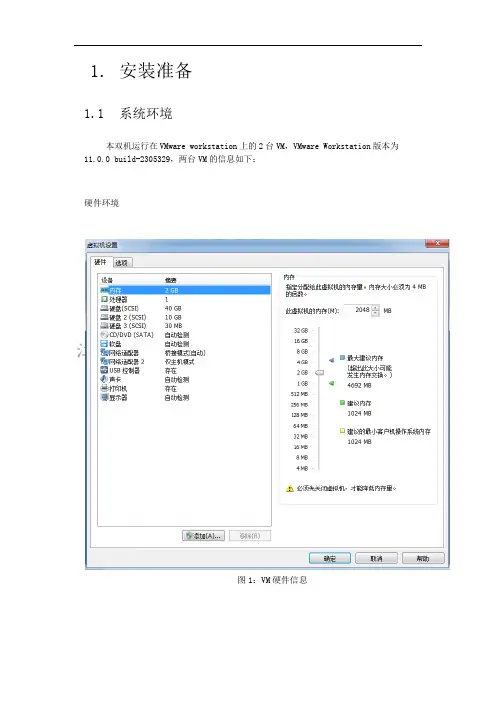
1. 安装准备1.1 系统环境本双机运行在VMware workstation上的2台VM,VMware Workstation版本为11.0.0 build-2305329,两台VM的信息如下:硬件环境图1:VM硬件信息1.2 网络配置IP 规划设置好的公网I P和私网IP信息如下:图2:公网和私网IP地址信息1.主机HA02 网络配置设置好的公网I P和私网IP信息如下:图3:公网和私网IP地址信息1.3 硬盘配置1.除了系统盘外,需要创建另外2种分区盘:镜像磁盘数据分区和c luster数据分区。
需要说明的是:镜像磁盘数据分区为NTFS分区或者FAT分区,cluster 数据分区需要是裸磁盘分区RAW格式。
分区如下:E 盘为数据分区.磁盘大小为10G,裸磁盘分区为30M。
镜像磁盘用于保证两台服务器数据同步,cluster数据分区用于双机通信。
现在重点演示cluster分区创建办法。
2.cluster分区方法:第一步,在磁盘2上单击右键,选择新建磁盘,如图4图4第二步,接着点击下一步,如图5,图5第三步,输入容量27M,点击下一步,如图6,图6第四步,指派盘符Q,点击一下步,如图7,图7第五步,接下来的步骤中,选择“不要格式化这个卷”选项,点击下一步,如图8所示,图8 第六步,选择完成,如图9图9 磁盘格式设置完成后的磁盘状况如图9显示图10由于H A01 和H A02 使用的是镜像磁盘,所以HA01 上磁盘划分好之后,在H A02 上进行相同配。
这样两台主机安装C luster 前的准备工作已全部完成,可以开始安装c luster。
2. BCP Express3.2安装和基础配置2.0 BCP Express3.2安装请分别在HA01服务器和HA02服务器上执行Inspur BCP Express 3.2的安装。
以下安装是以服务器HA01作为示范。
图11选择BCP-Express文件夹menu可执行文件双击安装图12单击选择BCP Windows版本13 单击BCP Windows版本开始安装图14点击下一步图15保持默认目录,选择下一步16点击安装图17保持默认端口图18镜像群集不需要设置过滤,保持默认,选择下一步图19 选择是,不进行过滤,单击下一步图20 选择登陆进行license授权图21 可以选择两种授权方式,我们选择第一种图22 选择复制类型即镜像型图23输入浪潮提供的信息进行授权图24 完成后选择[参照/删除],可看到所选L ICENSE 信息,或者点结束完成安装图25 点击完成重启电脑2.2 BCP Express3.2基础配置以下配置在客户端进行操作图26 输入IP,打开配置页面图27 启动配置向导图28确认启动配置向导图29群集命名图30 添加群集服务器图31 输入加入群集服务器ip图32 已经加入第二台服务器图33 设置镜像磁盘通信信息和公网私网ip信息图34 设置NP解决图35 添加组一般同一个应用服务为一个组,比如MS SQL,如果还需添加ORACLE,请另外添加一个组。
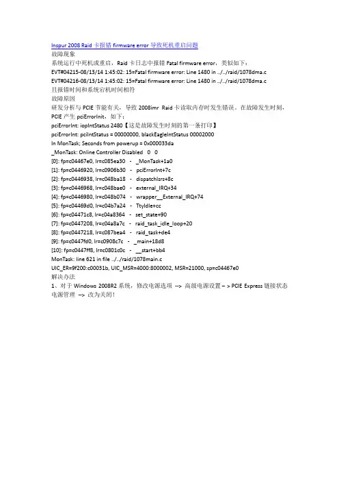
Inspur 2008 Raid卡报错firmware error导致死机重启问题故障现象系统运行中死机或重启,Raid卡日志中报错Fatal firmware error,类似如下:EVT#04215-08/13/14 1:45:02: 15=Fatal firmware error: Line 1480 in ../../raid/1078dma.cEVT#04216-08/13/14 1:45:02: 15=Fatal firmware error: Line 1480 in ../../raid/1078dma.c且报错时间和系统宕机时间相符故障原因研发分析与PCIE节能有关,导致2008imr Raid卡读取内存时发生错误。
在故障发生时刻,PCIE产生pciErrorInit,如下:pciErrorInt: iopIntStatus 2480【这是故障发生时刻的第一条打印】pciErrorInt: pciIntStatus = 00000000, blackEagleIntStatus 00002000In MonTask; Seconds from powerup = 0x000033da_MonTask: Online Controller Disabled00[0]: fp=c04467e0, lr=c085ea30- _MonTask+1a0[1]: fp=c0446920, lr=c0906b30- pciErrorInt+7c[2]: fp=c0446938, lr=c048ba18- dispatchIsrs+8c[3]: fp=c0446968, lr=c048bae0- external_IRQ+34[4]: fp=c0446980, lr=c048b074- wrapper__External_IRQ+74[5]: fp=c04469d0, lr=c04b7a24- TtyIdle+cc[6]: fp=c04471c8, lr=c04a8364- set_state+90[7]: fp=c0447208, lr=c04a8a7c- raid_task_idle_loop+20[8]: fp=c0447218, lr=c087bea4- raid_task+de4[9]: fp=c0447fd0, lr=c0908c7c- _main+18d8[10]: fp=c0447ff8, lr=c0801c0c- __start+bb4MonTask: line 621 in file ../../raid/1078main.cUIC_ER=9f200:c00031b, UIC_MSR=4000:8000002, MSR=21000, sp=c04467e0解决办法1、对于Windows 2008R2系统,修改电源选项--> 高级电源设置– >PCIE Express链接状态电源管理--> 改为关闭!或者升级OS到Windows 2008 R2 SP12、对于Linux系统,编辑/etc/grub.conf文件,在kernel一行最后添加pcie_aspm=off ,重启生效。


浪潮英信服务器服务常见问题咨询文档版本V1.2发布日期2022-08-05版权所有© 2021-2022浪潮电子信息产业股份有限公司。
保留一切权利。
未经本公司事先书面许可,任何单位和个人不得以任何形式复制、传播本手册的部分或全部内容。
商标说明Inspur浪潮、Inspur、浪潮、英信是浪潮集团有限公司的注册商标。
本手册中提及的其他所有商标或注册商标,由各自的所有人拥有。
内容声明您购买的产品、服务或特性等应受浪潮集团商业合同和条款的约束。
本文档中描述的全部或部分产品、服务或特性可能不在您的购买或使用范围之内。
除非合同另有约定,浪潮集团对本文档的所有内容不做任何明示或默示的声明或保证。
文档中的示意图与产品实物可能有差别,请以实物为准。
本文档仅作为使用指导,不对使用我们产品之前、期间或之后发生的任何损害负责,包括但不限于利益损失、信息丢失、业务中断、人身伤害,或其他任何间接损失。
本文档默认读者对服务器产品有足够的认识,获得了足够的培训,在操作、维护过程中不会造成个人伤害或产品损坏。
文档所含内容如有升级或更新,恕不另行通知。
技术支持技术服务电话:4008600011地址:中国济南市浪潮路1036号浪潮电子信息产业股份有限公司邮箱:***************邮编:250101前言目标受众本手册主要适用于以下人员:●技术支持工程师●产品维护工程师建议由具备服务器知识的专业工程师参考本手册进行服务器运维操作。
符号约定在本文中可能出现下列符号,它们所代表的含义如下。
变更记录版本时间变更内容V1.0 2021-10-11 首版发布V1.1 2022-01-06 刷新格式V1.2 2022-08-05 •新增章节“1.1.5 9560-8i/16i RAID卡在BIOS下配置Firmware Device Order选项的方法”•更新“2 故障排查”目录1技术咨询类 (1)1.1BIOS/BMC相关咨询 (1)1.1.1设置Legacy启动模式 (1)1.1.2在BIOS中设置BMC管理IP地址 (1)1.1.3在BIOS中查看9361-8i RAID卡缓存信息 (5)1.1.49361-8i RAID卡在BIOS中配置RAID 5的方法 (7)1.1.59560-8i/16i RAID卡在BIOS下配置Firmware Device Order选项的方法 151.1.6如何获取以及升级BIOS/BMC (16)1.2操作系统驱动安装 (17)1.2.1RAID卡驱动下载 (17)2故障排查 (19)2.1常见硬件问题 (19)2.1.1开机不加电 (19)2.1.2加电无显示 (19)2.1.3前面板指示灯告警 (20)2.1.4开机后卡在自检或其它界面 (21)2.1.5电源模块指示灯不亮或亮琥珀色 (21)2.1.6硬盘指示灯异常 (22)2.1.7系统风扇噪音过大 (22)2.1.8服务器存在报警声 (23)2.1.9键盘、鼠标不可用 (23)2.1.10USB接口问题 (24)2.2常见系统软件问题 (24)2.2.1安装OS常见问题 (24)2.2.2PXE启动失败 (25)2.2.3内存容量显示异常 (26)2.2.4OS下网络异常 (26)1技术咨询类1.1BIOS/BMC相关咨询1.1.1设置Legacy启动模式进入“BIOS > Advanced > CSM Configuration”页面,将“CSM Support”设置为“Enabled”,然后修改“Boot option filter”设置为“legacy only”,“Option ROM execution”设置为“Auto”即可。

《管理沟通(二)》在线平时作业1-00001试卷总分:100 得分:100一、判断题 (共 25 道试题,共 100 分)1.自我暗示不属于自我沟通。
答案:错误2.危机沟通可以降低危机的冲击,并存在化危机为转机的可能。
答案:正确3.说服属于指导性沟通策略。
答案:正确4.演讲是一个双向沟通的过程。
答案:正确5.心灵相通是指交流双方采取支持的、坦诚的态度交换意见。
答案:正确6.谈判开始一定要先声夺人、这样才能占得先机。
答案:错误7.演讲是一个双向沟通的过程。
答案:正确8.创新型上司不喜欢约定时间,沟通时要使其参与到问题的解决中来。
答案:正确9.办公室的主要倾听障碍源有不平等造成的心理负担,紧张,他人或电话打扰。
答案:正确10.面谈过程一定是互有听和说的谈话。
答案:正确11.团队建设失败的主要原因是沟通不足。
答案:正确12.好的倾听者会寻找方法来克服倾听过程中潜在的障碍。
答案:正确13.讨论会中主要倾听障碍源有缺乏从大量散乱信息中发现闪光点的洞察力。
答案:正确14.沟通的可信度包括初始可信度和后天可信度。
答案:正确15.互联网使人们的沟通方式增加了许多渠道。
答案:正确16.倾听是认真地听、积极地听。
答案:正确17.手势也能在沟通中传递不同的信息。
答案:正确18.征询属于指导性沟通策略。
答案:错误19.电子邮件是传递私人信息的最好媒介。
答案:正确20.自我认知也称为自我意识,是对自己存在的觉察,包括对自己的行为和心理的认知。
答案:正确21.团队不同于群体。
答案:正确22.自我思考属于自我沟通的方式。
答案:正确23.自定义幻灯片深受演讲者推崇,文字视觉效果较生动。
答案:正确24.手势也能在沟通中传递不同的信息。
答案:正确25.演讲后接受提问容易失去听众的注意力。
答案:正确《管理沟通(二)》在线平时作业2-00001试卷总分:100 得分:100一、判断题 (共 25 道试题,共 100 分)1.沟通是企业和管理者重要的职责之一。

浪潮存储系统SCOM主机插件用户手册文档版本1.1发布日期2018-06-30适用版本SCOM_V3.3.1尊敬的存储系统用户:衷心感谢您选用了浪潮存储系统!本手册介绍了本存储系统的主机插件相关配置管理等信息,有助于您更详细地了解和便捷地使用本款存储系统。
浪潮拥有本手册的版权。
未经浪潮许可,任何单位和个人不得以任何形式复制本用户手册。
浪潮保留随时修改本手册的权利。
本手册中的内容如有变动恕不另行通知。
如果您对本手册有疑问或建议,请向浪潮电子信息产业股份有限公司垂询。
技术服务电话:4008600011地址:中国济南市浪潮路1036号浪潮电子信息产业股份有限公司邮编:250101声明在您正式使用本存储系统之前,请您先阅读以下声明。
只有您阅读了以下声明并且同意以下各条款后,方可正式开始使用本存储系统;如果您对以下条款有任何疑问,请和您的供货商联系或直接与我们联系。
如您未向我们就以下条款提出疑问并开始使用本系统,则是默认您已经同意了以下各条款。
1.在您使用的存储系统出现任何硬件故障或您希望对硬件进行任何升级时,请您将机器的详细硬件配置反映给我们的客户服务中心;您不要自行拆卸存储系统机箱及机箱内任何硬件设备。
2.本存储系统的内存、CPU、CPU散热片、风扇、硬盘托架、硬盘等都是特殊规格的,请您不要将它们和任何其他型号机器的相应设备混用。
3.您在使用存储系统过程中遇到的任何软件问题,我们希望您首先和相应软件的提供商联系,由他和我们联系,以方便我们沟通、共同解决您遇到的问题。
对于如数据库、网络管理软件或其他网络产品等的安装、运行问题,我们尤其希望您能够这样处理。
4.如果上架安装本存储系统,请先仔细阅读相关产品手册中的快速安装指南。
浪潮致力于产品功能和性能的持续提升,这可能导致部分功能及操作与手册描述有所差异,但不会影响使用,如果您有任何使用疑难问题,请与我们的客户服务中心联系。
5.我们特别提醒您:在使用过程中,注意对您的数据进行必要的备份。
浪潮信息(Inspur)是中国领先的信息技术解决方案提供商,专注于云计算、大数据、人工智能和物联网等领域。
以下是关于浪潮信息的概念:
1. 公司概述:浪潮信息成立于1991年,总部位于中国山东省济南市。
作为中国领先的信息技术企业,浪潮信息致力于提供全方位的IT产品和解决方案,包括服务器、存储设备、超级计算、云计算平台、大数据分析等。
2. 技术创新:浪潮信息一直注重技术创新和研发投入,拥有强大的研发团队和先进的技术实力。
公司持续推动人工智能、物联网、区块链等前沿技术的研究和应用,并积极与全球合作伙伴合作,推动技术创新和产业升级。
3. 云计算和大数据:作为云计算领域的领先者,浪潮信息提供全面的云计算解决方案,包括云平台、云存储、云安全等。
同时,公司还致力于大数据技术的研究和应用,帮助企业实现数据驱动决策和业务创新。
4. 全球业务:浪潮信息在全球范围内拥有广泛的业务覆盖,与全球众多的合作伙伴建立了紧密的合作关系。
公司的产品和解决方案在教育、政府、金融、电信、制造等多个行业得到广泛应用。
5. 可持续发展:浪潮信息致力于可持续发展,将环境保护和社会责任视为核心价值。
Product Introduction of Inspur ServerNF5280M42014V0.5Inspur Server NF5280M4Specially designed for the optimization ofnew data centers and new applications⏹Product PositioningYingxin NF5280M4 is a high-end product with flagship dual 2U rack developed by Inspur for the optimization of new data centers and new applications, which is much better based on the high quality of the previous products. This product maintains the high quality and high reliability of Inspur servers. Meanwhile, it also has the highest performance in similar products, ideal expandability and good management features, so it’s especially suitable for telecommunication, financial and large enterprises and other users having strict requirements for servers. With a system design of ingenuity, it perfectly shows such features as high efficiency, reliability, smartness and high expandability within a limited space and is suitable for all the key applications having high standard requirements for computing, storage and communication.⏹Key Points●High efficiency, smartness, elastic expansion and optimization for new applicationsWith new smart computing speedup technology, it can adjust or optimize the performance according to the application of the user.With the latest memory technology, a higher density and a larger capacity, it provides a better performance for the virtualization and business processing of the enterprise.With the latest hard disk interface technology, it eliminates the storage bottlenecks and largely improves the storage performance.It can provide a flexible and elastic I/O function, including the integrated expansion slot supporting PCIe3.0, to realize the maximum speed network I/O. The user can expand it freely according to the requirements for the network bandwidth to realize a network performance leap.It provides abundant I/O slots. 6 standard high-speed PCI-E 3.0 expansion slots and a dedicated PCI-E expansion slot can be provided in the limited space of the 2U case, and up to 4 full-length and full-height cards can be supported. Therefore, it meets requirements of the high-end customers for system functions and performances.●Environment-friendliness, energy saving, safety, reliability and optimization for new datacentersThe system environment dynamic perception and control technology optimized by Inspur recently can transfer the internal temperature information of the server in real time via the multiple temperature sensors precisely provided within the system, dynamically adjust the hot-plug redundant fans within the equipment and support the advanced air cooling system to achieve the best operating environment, so as to ensure the stable operation of the system.With the elements of low power consumption and the highest transformation efficiency within the industry, as well as the high efficiency power supply design, it can save up to 20% of energy compared with other schemes. The Inspur SmartPower technology can help the user monitor and control the power consumption of the system precisely in real time, so as to improve the energy efficiency performance of the whole IT architecture further.It can support the latest trustable encryption technology to protect the data security of the customer.●Easy maintenance, easy management and improvement of working efficiencyThe embedded smart server management chip can realize various management functions, such as complete remote system monitoring of IPMI 2.0, remote KVM and virtual media.It can support the embedded large capacity flash memories, internally loaded Inspur Ruijie server management suite (v5.2) and UEFI smart firmware, and largely simplify the equipment deployment, management and maintenance work for the user.In order to simplify the equipment management in the data center environment, the external visualized management module of Inspur will be launched to be used together with the optical path diagnosis function of Inspur, so that the management personnel can determine the equipment to be maintained quickly to largely reduce their working pressure and improve their working efficiency.⏹Application Examples●Large databases and core business software in government and enterprises having highrequirements for the performance●Various network servers having very high requirements for memory and disk expansion andnetwork I/O capacity●High performance clusters pursuing ultra-high performances, such as rendering operation, CADin manufacturing industry and CAE.⏹SpecificationModel NF5280M4Processor 2 Intel® Xeon ® E5-2600V3 processorsMemory 24 memory slots, support DDR4-2133 memory, 1536GB at the maximum (when using the single 64GB memory). Support 8, 16, 32G 1600/1866/2133 currently.Support advanced functions such as advanced memory error correction, memory mirroring and memory sparing.Hard diskcontrollers8-channel SAS 6Gb and 12 Gb disk controller are optionalRAID Standard configure SAS disk controller, support RAID 0/1/10 and RAID 5, 50 are available with optional component, SAS RAID controller with cache and support RAID 0/1/5/6/10/50/60 is optional and extensible to protect the batteryStorage Front:Up to 25* 2.5-inch hot-swap SATA/SAS hard disks or SSD Standard configuration 2.5-inch* 8/ 2.5-inch* 16/ 2.5-inch* 24; Up to 12 *3.5-inch hot-swap SATA/SAS hard disks or SSD Standard configuration 3.5-inch* 4/ 3.5-inch* 8/ 3.5-inch* 12; Rear:Up to 4*2.5-inch hot-swap SATA/SAS hard disks or SSDI/O expansion slots Standard configuration: 1 PCI-E 3.0 x16, 4 PCI-E 3.0 x8 (various adapter cards can be selected and 6 PCI-E can be supported at most).For 1 processor to be configured, only 1 PCI-E 3.0 x16 and 2 PCI-E 3.0 x8 are available.Integrated I/O port Rear: 2 USB 3.0 ports and 1 VGA portFront: 1 USB 3.0 port and 1 VGA portBuilt-in: 2 USB 3.0 ports and 1 internal serial portNetwork controller Integrated 2*1GbE controllers, support virtualization acceleration, network acceleration, load balancing, redundancy and other advanced functions. In addition, 2 special extension technology-based 10Gb Ethernet controllers can be added.Power supply High efficiency hot-swap redundant power supply: standard configure platinum level, titanium level is optional, support PMbus and carries out functions of Node Manager 3.0; hot-swap single power supply is optionalGraphics card Display controller with video memory of 16MB is integrated.CD driver Internal Slim DVD-RW CD driver or external DVD-RW CD driver equipped with USB interface is optional before factory deliveryInternal flashmemoryInternal flash memory of large capacity is available.Management function Integrated system management chip, support IPMI2.0, KVM over IP and virtual media Support Inspur Ruijie server management suiteSupport external visualized management module of Ruijie and provide local visual system monitoring and fault diagnosis functions.Operating system supported Windows 2012R2, Windows 2012R2, Windows 2008R2 64Bit, VMware 5.5, Citrix 6.2 64Bit, Soloris 11, SuSE Linux Enterprise Server 11 SP2 64Bit etc.Operating system versions are different under different configuration. Please consult Inspur for detailsOfficial OS certification Windows 2012R2 & 2012 Windows 2008R2 VMware 5.5Citrix 6.2Soloris 11Workingambienttemperature10 °C-35 °CPower voltage110-240VInternationalcertificationCCC, FC, CE, ULCase W (width) 447 mm; H (height) 87 mm; D (depth) 720 mmReference25KG weight。
WEB 管理系统用户指南Web 界面配置手册用户指南WEB 管理系统用户指南目录第 1 章路由器WEB管理系统概述 (1)1.1 路由器配置系统概述 (1)1.2 WEB配置风格约定 (1)1.3 WEB配置约定 (2)1.3.1 列表功能与操作约定 (2)1.3.2 通用符号约定 (5)1.3.3 键盘操作约定 (5)1.3.4 其他表达约定 (5)1.4 出厂配置 (6)1.5 系统运行环境 (6)1.5.1 硬件环境 (6)1.5.2 软件环境 (7)1.6 术语与缩略语 (7)1.7 功能特性简述 (8)1.8 典型应用 (11)第 2 章配置准备 (13)2.1 网络设置 (13)第 3 章配置指南 (16)3.1 登录WEB管理系统 (16)3.2 WEB管理系统主界面 (16)3.2.1 系统管理员的界面 (16)3.2.2 配置受限用户的界面 (17)3.2.3 菜单栏 (18)3.2.4 中英文切换 (19)3.2.5 设备面板映射 (19)3.2.6 系统运行信息栏 (19)第 4 章首页信息 (20)4.1 实时运行信息 (20)第 5 章快速向导 (22)5.1 快速上网向导 (22)5.1.1 快速上网向导概述 (22)5.1.2 向导第1步:修改当前用户密码 (22)5.1.3 向导第2步:配置广域网口参数 (23)5.1.4 向导第3步:设置上网主机数量 (25)5.1.5 向导第4步:配置局域网口参数 (26)5.1.6 向导第5步:设置内网主机IP地址分配方式 (27)5.2 QoS流控向导 (28)5.2.1 QoS流控向导概述 (28)5.2.2 选择QoS流控默认策略 (29)- I -WEB 管理系统用户指南5.2.3 QoS智能流控默认参数配置 (29)5.2.4 IP智能流控默认参数配置 (30)5.2.5 QoS不限速配置 (32)5.2.6 群组QoS配置提示 (32)5.3 上网管理向导 (33)5.3.1 上网管理向导概述 (33)5.3.2 上网管理向导:配置上网管理默认策略 (33)5.3.3 上网管理向导:上网管理默认策略配置成功 (34)5.3.4 上网管理向导:选择群组 (35)5.3.5 上网管理向导:添加群组 (35)5.3.6 上网管理向导:配置上网管理群组策略 (36)5.3.7 上网管理向导:群组策略配置成功 (36)第 6 章接口配置 (38)6.1 WAN口配置 (38)6.1.1 WAN广域网口信息列表 (38)6.1.2 WAN广域网口配置 (39)6.2 LAN口配置 (42)6.2.1 LAN(局域网)口信息列表 (42)6.2.2 LAN局域网口配置 (43)6.3 工作模式 (44)6.3.1 接口工作模式 (44)6.3.2 修改接口工作模式 (44)6.4 修改MAC (45)6.4.1 接口MAC信息 (45)6.4.2 修改MAC地址 (46)6.5 端口监控 (46)6.5.1 端口监控配置 (47)6.6 端口重组 (47)6.6.1 端口重组配置 (47)第 7 章多线路策略 (49)7.1 线路组合模式 (49)7.2 应用调度 (49)7.3 线路侦测 (50)第 8 章路由配置 (52)8.1 默认路由 (52)8.1.1 默认路由信息显示 (52)8.1.2 添加或修改默认路由 (52)8.2 静态路由 (53)8.2.1 静态路由信息显示 (53)8.2.2 添加或修改静态路由 (54)第 9 章网络选项 (56)- II -WEB 管理系统用户指南9.1端口映射 (56)9.1.1端口映射 (56)9.1.2分段映射 (57)9.1.3特殊映射 (58)9.1.4 DMZ主机 (59)9.2时间段配置 (59)9.2.1循环时间段配置 (59)9.2.2单次时间段配置 (60)9.3连接数限制 (61)9.3.1连接数限制全局配置 (61)9.3.2连接数限制个性化配置 (61)9.4 NAT 访问控制 (62)9.4.1 NAT简介 (62)9.4.2 NAT访问控制 (62)9.5 DNS 配置 (63)9.6 DDNS 配置 (64)9.7 DHCP 配置 (64)9.8 PPPOE 服务器 (65)9.8.1 PPPOE 服务端配置信息 (65)9.8.2添加或修改PPPOE服务 (66)9.8.3 PPPOE 会话信息 (67)9.9 UPnP 配置 (68)9.9.1启用/停止UPnP服务 (68)9.9.2 UPnP NAT映射信息列表 (68)9.10 主机伪装 (69)9.10.1 修改“主机伪装”配置 (69)第 10 章ARP安全 (70)10.1 ARP手动绑定 (70)10.1.1 ARP静态绑定信息列表 (70)10.1.2 添加或修改ARP静态绑定配置 (70)10.2 ARP扫描绑定 (71)10.3 IP+MAC地址过滤 (72)10.3.1 “IP+MAC过滤”列表 (72)10.3.2 添加或修改“IP+MAC过滤”配置 (73)10.4 ARP欺骗侦测 (73)10.4.1 启用/停止ARP欺骗侦测 (73)10.4.2 查看ARP欺骗侦测列表 (74)10.5 免费ARP (74)10.5.1 修改“免费ARP”配置 (74)第 11 章网络安全 (75)11.1 防火墙配置 (75)- III -WEB 管理系统用户指南11.1.1 启用/停止接口防火墙服务 (75)11.1.2 查看防火墙规则信息列表 (76)11.1.3 添加防火墙规则 (77)11.1.4 修改防火墙规则 (79)11.1.5 删除防火墙规则 (80)11.2 反病毒配置 (80)11.2.1 查看反病毒信息列表 (81)11.2.2 添加反病毒规则 (81)11.2.3 修改反病毒规则 (82)11.2.4 删除反病毒规则 (82)11.3 攻击防御 (83)11.3.1 修改“攻击防御”配置 (83)11.4 URL过滤 (83)11.4.1 启用/停止URL过滤服务 (84)11.4.2 查看URL过滤规则列表 (84)11.4.3 添加URL过滤规则 (85)11.4.4 修改URL过滤规则 (85)11.4.5 删除URL过滤规则 (86)11.5 关键字过滤 (86)11.5.1 启用/停止关键字过滤服务 (87)11.5.2 查看关键字过滤规则列表 (87)11.5.3 添加关键字过滤规则 (87)11.5.4 修改关键字过滤规则 (88)11.5.5 删除关键字过滤规则 (88)11.6 DMZ端口配置 (89)11.6.1 DMZ端口配置 (89)11.6.2 DMZ区服务配置 (89)第 12 章上网行为管理 (91)12.1 全局配置 (91)12.1.1 启动上网行为管理 (91)12.1.2 ISP带宽配置 (92)12.1.3 功能配置 (95)12.1.4 QOS流控默认配置 (98)12.1.5 高级配置 (100)12.2 群组管理 (101)12.2.1 群组配置综合向导 (102)12.2.2 群组配置综合向导:添加群组 (103)12.2.3 群组配置综合向导:群组创建成功 (103)12.2.4 群组配置综合向导:配置上网管理群组策略 (104)12.2.5 群组配置综合向导:QOS策略配置确认 (105)12.2.6 群组配置综合向导:QoS模式选择 (105)12.3 优先服务管理 (106)- IV -WEB 管理系统用户指南12.3.1 邮件优先管理 (106)12.3.2 其它业务优先管理 (106)12.4 黑白名单 (107)12.5 推送网页通知 (108)12.5.1 推送内容 (108)12.5.2 推送地址 (108)12.6 状态查询 (109)12.7 上网记录查询 (110)12.7.1 最近上网信息 (110)12.7.2 上网主机列表 (111)12.7.3 主机上网详细信息 (111)12.7.4 上网记录配置 (111)第 13 章虚拟专网 (113)13.1 IPSEC配置 (113)13.1.1 WAN口的IPSEC列表信息 (113)13.1.2 添加或修改WAN口的IPSEC配置 (114)13.1.3 IPSEC本地配置 (117)13.1.4 查看IPSEC会话信息 (117)13.2 PPTP配置 (118)13.2.1 PPTP客户端配置信息列表 (118)13.2.2 添加或修改PPTP客户端配置 (118)13.2.3 PPTP服务器配置信息列表 (119)13.2.4 添加或修改PPTP服务器配置 (120)13.2.5 PPTP会话信息 (122)13.3 L2TP配置 (122)13.3.1 L2TP客户端配置信息列表 (122)13.3.2 添加或修改L2TP客户端配置 (123)13.3.3 L2TP服务器配置信息列表 (124)13.3.4 添加或修改L2TP服务器配置 (124)13.3.5 L2TP会话信息 (126)13.4 IPIP配置 (127)13.4.1 IPIP隧道信息列表 (127)13.4.2 添加或修改IPIP配置 (127)13.5 GRE配置 (128)13.5.1 GRE隧道信息列表 (128)13.5.2 添加或修改GRE配置 (129)13.6 拨号用户管理 (130)13.6.1 拨号用户信息列表 (130)13.6.2 拨号用户管理配置 (131)第 14 章系统管理 (132)14.1 用户管理 (132)- V -WEB 管理系统用户指南14.1.1 管理员信息列表 (132)14.1.2 添加或修改登录用户密码和权限 (132)14.2 时钟管理 (133)14.3 软件升级 (133)14.3.1 备份IOS软件 (134)14.3.2 升级IOS软件 (134)14.4 日志管理 (134)14.5 远程管理 (135)14.5.1 Web管理 (135)14.5.2 SNMP管理 (136)14.5.3 NAT监控管理 (136)14.6 诊断工具 (137)14.7 策略库管理 (137)14.7.1 策略库在线升级 (137)14.7.2 策略库手动升级 (137)14.8 重新启动 (138)14.9 配置导入导出 (139)14.9.1 导出当前配置信息 (139)14.9.2 导入配置文件 (139)14.10 恢复出厂配置 (140)第 15 章监控信息 (141)15.1 端口信息 (141)15.2 系统信息 (141)15.3 DHCP信息 (141)15.4 路由信息 (142)15.5 日志信息 (142)15.6 连接数监控 (143)15.7 流量监控 (144)15.7.1 流量监控状态信息 (144)15.7.2 流量趋势图 (145)15.7.3 应用程序流量详细信息 (147)15.8 行为监控 (148)第 16 章VLAN管理 (149)16.1 VLAN管理 (149)16.1.1 设备状态 (149)16.1.2 物理端口配置 (150)16.1.3 二层配置 (156)第 17 章技术支持信息 (161)17.1 注意事项 (161)17.2 技术支持 (161)附录 A 常见问题 FAQ (162)- VI -第1章路由器WEB管理系统概述1.1. 路由器配置系统概述非常感谢您选用我们的高速智能路由器系列产品。
Inspur NOS安全技术白皮书文档版本V1.0发布日期2022-12-16版权所有© 2022浪潮电子信息产业股份有限公司。
保留一切权利。
未经本公司事先书面许可,任何单位和个人不得以任何形式复制、传播本手册的部分或全部内容。
商标说明Inspur浪潮、Inspur、浪潮、Inspur NOS是浪潮集团有限公司的注册商标。
本手册中提及的其他所有商标或注册商标,由各自的所有人拥有。
技术支持技术服务电话:400-860-0011地址:中国济南市浪潮路1036号浪潮电子信息产业股份有限公司邮箱:***************邮编:250101前言文档用途本文档阐述了浪潮交换机产品Inspur NOS的安全能力及技术原理。
注意由于产品版本升级或其他原因,本文档内容会不定期进行更新。
除非另有约定,本文档仅作为使用指导,本文档中的所有陈述、信息和建议不构成任何明示或暗示的担保。
读者对象本文档提供给以下相关人员使用:●产品经理●运维工程师●售前工程师●LMT及售后工程师变更记录目录1概述 (1)2缩写和术语 (2)3威胁与挑战 (3)4安全架构 (4)5安全设计 (5)5.1账号安全 (5)5.2权限控制 (5)5.3访问控制 (6)5.4安全协议 (6)5.5数据保护 (7)5.6安全加固 (7)5.7日志审计 (7)5.8转发面安全防护 (7)5.9控制面安全防护 (8)6安全准测和策略 (9)6.1版本安全维护 (9)6.2加强账号和权限管理 (10)6.3TACACS+服务授权 (10)6.4加固系统安全 (12)6.4.1关闭不使用的服务和端口 (12)6.4.2废弃不安全通道 (12)6.4.3善用安全配置 (12)6.5关注数据安全 (13)6.6保障网络隔离 (14)6.7基于安全域访问控制 (14)6.8攻击防护 (15)6.9可靠性保护 (16)7安全发布 (18)随着开放网络的快速发展,白盒交换机做为一种软硬件解耦的开放网络设备,应用越来越广泛。
浪潮发展历程
浪潮(Inspur)是中国一家知名的信息技术企业,成立于2002年。
以下是浪潮发展的历程:
创办初期,浪潮专注于服务器的研发和制造。
凭借着高品质的产品和出色的服务,浪潮很快在国内服务器市场占据了一席之地。
随着中国信息技术产业的迅猛发展,浪潮逐渐开始拓展国际市场。
他们积极参与国际合作和竞标,提供IT解决方案和产品。
2006年,浪潮成功推出了自主研发的高性能服务器,成为中
国首家实现服务器国产化的企业之一。
这一里程碑的突破在国内引起了广泛的关注和认可。
为了进一步提高自主研发的能力,浪潮成立了中国第一个国家级企业技术中心。
他们加大了研发投入,推动技术创新,不断提升产品性能和质量水平。
随着云计算的兴起,浪潮迅速抓住机遇,并积极布局云计算产业链。
他们成立了浪潮云,提供全面的云计算服务和解决方案,帮助用户实现数字化转型。
为了进一步拓展市场,浪潮积极参与国内外的并购活动。
他们收购了多家技术先进的企业,不断壮大自己的实力和业务范围。
如今,浪潮已经成为全球领先的信息技术企业之一,业务遍及
全球多个国家和地区。
他们为各行各业的客户提供全面的数字化解决方案,推动智能科技的发展。