“帮得佳”产品演示步骤
- 格式:doc
- 大小:206.50 KB
- 文档页数:15
植雅、帮得佳系列(6个单品)演示方法建议1、帮得佳洗洁精:清洗苹果1.1 工具推荐:装清水的盆1个,苹果1个,白纸1张,帮得佳净亮洗洁精、稀释瓶1.2 演示方法:准备1个苹果,放入装清水的盆搓洗若干下。
放在白纸上,观察水渍(无变化)。
在苹果上滴3-5滴的帮得佳洗洁精稀释液搓洗。
放在白纸上,等2分钟,观察在白纸上的水渍。
1.3 实验现象:白纸上的水渍变黑、变脏。
1.4 结论解释:洗洁精含有界面活性剂——无患子+APG,能溶解水果表面的灰尘、石蜡、防腐剂等物质。
2、帮得佳预洁剂:清洗圆珠笔划痕2.1 工具推荐:纱布2块,蓝色圆珠笔1支,含盖的广口瓶2个,胶搅拌棒1支,镊子1个,帮得佳预洁剂、竞品1(安利预洗喷洁剂)、帮得佳洁衣液、竞品2(安利多效倍洁洗衣液)2.2 演示方法:在2块纱布上用圆珠笔分别划上3条痕迹。
分别放在瓶盖A、B里,喷等量的帮得佳及竞品预洁剂,同时在装有清水的广口瓶A、B中,分别滴一滴洁衣液。
静置2分钟后,用镊子将纱布分别分入广口瓶A、B中。
用搅拌棒分别搅拌15下。
用镊子夹起纱布,放置瓶盖上观察清洗情况。
2.3 实验现象:帮得佳能很快地清洗掉纱布上的圆珠笔划痕。
2.4 结论解释:预洁剂含独有的多元洁净因子和天然草本精华——无患子,性质温和且洗涤力强劲,能快速润湿和渗入纤维与污垢之间,可发挥松动分解的作用,使污垢彻底脱离衣物,显著提高对顽固污渍的洗涤效率和洗涤效果。
3、帮得佳多功能清洁剂:清洗玻璃上粉尘3.1 工具推荐:胶棒1支,彩色粉笔1支,滴管1支,勺子1个,干净玻璃(或瓷砖)1块,湿毛巾1条,帮得佳多功能清洁剂3.2 演示方法:在玻璃上涂固体胶,在上面刨上粉笔灰,等1分钟待其凉干。
用滴管吸适量清洁剂,滴在笔灰上面。
再用湿毛巾抹干净,进行观察。
3.3 实验现象:快速将玻璃上的粉笔和固体胶的混合物清洗干净。
3.4 结论解释:APG绿色洁净因子,轻松去除多种材质表面污渍,浓缩免冲洗配方,性质温和,令家居持久亮洁。

小型产说会运作基本步骤一、产品推介会的运作步骤(一)会前1、与银行充分沟通,确认说明会选择产品、参加人数等,并与银行明确分工。
2、费用签批。
3、内部工作人员的确定分工与职责确认。
4、内部工作人员按既定分工分头准备。
(1)及时跟踪网点准客户积累情况(2)确认参会名额,组织会前演练。
(3)主讲、主持分头准备,反复演练。
(4)会场的选定,确认布置方案。
(5)请柬印制、奖项奖品确定、附加价值的策划包装。
(6)请柬发放、奖品采购、资料分装、设备准备。
(7)音乐素材等其他准备。
(8)银行、公司参会领导确认。
5、会前一天相关准备(1)设备、资料、奖品运送。
(2)会场布置、设备安装、试运行。
(3)所有人员现场走台。
(4)其他工作进展确认。
6、会议当天提前两小时相关准备(1)设备、资料、奖品检查清点。
(2)会场布置细节复检。
(3)投影设备、音像设备、扩音设备等现场调试。
(4)“责任人”调度所有人员现场彩排。
二、会中1、提前半小时迎候来宾2、按既定时间会议准点开始3、会议结束,恭送来宾三、会后1、追踪网点人员督促客户保费进账2、分析相关数据,制作报告,与银行领导分析研讨3、感谢银行领导及网点人员,可赠送礼品或聚餐4、完成费用结算、报销二、产品推介会会议流程1、来宾入场:至少提前30分钟所有准备工作就绪2、主持人宣布会场秩序要求:正式开场前1分钟3、正式主持人登台致开场辞:5分钟以内4、银行领导致辞:5分钟以内5、游戏时间/有奖知识问答:5分钟以内6、理财沟通:40分钟以内7、预卖时间(客户沟通交流):30分钟以内8、抽奖时间:10分钟以内9、欢送嘉宾:确认最后一名嘉宾离场后方可开始清理会场三、理财产品推介会人员配备1、责任人:1名整场推介会项目包括会前、会中、会后等各项事宜总负责者,推介会现场总调度、总协调者。
要求有全局观念,思路清晰细致,沟通协调能力强。
2、主讲人:1名产品代言人:产品介绍者。
要求熟悉产品,形象端庄,有感染力,普通话标准。

茂旭公司SOYAL系列主流产品初次使用之操作手册茂旭安防工程设备(上海)有限公司二ΟΟ六年五月十日本操作手册出版说明为了更加方便指引SOYAL产品的新用户对SOYAL产品进行测试、使用,特由茂旭上海公司组织相关技术人员进行整理、汇总并出版了本操作手册,希望借此手册能够您及您的公司带来方便,同时也感谢您和您公司选择了SOYAL产品,非常感谢!撰稿人:郑春生 平庆跃--郑春生 致MSN:zhengchunsheng78@目录索引SOYAL AR-721HV3/AR-721HV3-1356键盘型三合一门禁机SOYAL AR-727HV3/AR-727HV3-1356液晶型三合一门禁机SOYAL AR-829E/AR-829E-1356考勤门禁一体机SOYAL AR-716EV2/EV3十六门485型门禁控制器SOYAL AR-716Ei十六门TCPIP网络型门禁控制器721HV3/721H1356初次投入使用的操作流程第一步、软件安装安装701ServerSetup.exe和701ClientSetup.exe,安装完成后电脑系统会自动提示重新启动计算机,701Server会默认设置为随计算机自动运行,可以在桌面屏幕或下角的状态栏中看到“S”图标。
注:701Server和701Client这个两个软件可以在随产品附送的光盘中找到,或到我们的FTP站点下载:FTP://,也可以到我们的网站上下载:。
第二步、硬件安装1、721HV3的485通讯为二芯线插头接插座CN4上,绿线和蓝线分别为(485-)和(485+);2、721HV3可以直接接电脑:485通讯线可以直接接801CM(232转485通讯转换器)的绿线和蓝线,再通过COM口进入电脑,达到数据的传输;3、721HV3中的八芯线插头,接入插座CN1,红线和黑线接DC12V电源正、负极(接线情况可以参考721HV3的硬件说明书);4、721HV3还可以通过716EV2控制器连入电脑,485通讯线细蓝、细绿连入控制器的CH1或是CH2端口,再由控制器的HOST-、HOST+连入电脑;5、801CM和721HV3都通电后,使用701Server和701Client进行相应的设置。
产品示范技巧与话术灵芝黄胶囊的演示方法:一、准备材料:灵芝黄胶囊4粒,55度以上白酒,透明一次性杯子(或玻璃杯)2个,搅拌棒1个二、演示方法:将白酒分别倒入两个杯子里,占杯子的1/5 为最佳量,让喝酒的人尝一下酒的度数,然后再其中一个杯子里放入4粒灵芝黄(把胶囊拆开倒入粉粒,受潮成块的不用)用搅拌棒搅匀,静置6—10分钟,再让新人来品尝一下,并说出其度数。
这个试验的目的是告诉人们灵芝黄有很好的解毒功效,它可以排除体内毒素,降低酒精对人体肝脏的伤害。
三、作用:辅助抑制肝瘤,延缓衰老,全面提升人体免疫力。
维康素的演示方法:一、准备材料:维康素2粒、大米1小匙、碘伏、吸管1个、搅拌棒一根、白纸1张、帮得佳示范杯1个、清水1杯。
二、演示方法:在帮得佳示范杯中倒入1/3的清水,放入1小匙大米,用吸管吸入碘伏,放入盛大米水的杯子中4滴,看水的颜色微微发黄,并且大米颜色变淡蓝。
然后把2粒维康素压碎倒入水中,用搅拌棒搅拌几下,看水及大米的颜色被逐渐还原成白色。
证明维康素有很强的抗氧化的作用。
三、在搅拌过程中边做边讲解,维康素不仅有很强的抗氧化作用,其还能激活人体自身抗氧化体系(激活人体SOD酶的活性)延缓衰老,修复化学性肝损伤,提高人体抗辐射能力。
无限极钙片的对比演示将我们的钙片(研磨成粉状)、他牌同类产品(市场常用的是乐力钙),还有洗衣粉,分别放入3个杯中,然后加入50-100ML的水(最好是纯净水),再滴入酚酞溶液,观察颜色变化。
我们的无变化,他牌钙片颜色变红,甚至超过了洗衣粉的颜色。
说明,他牌产品偏碱性,我们的钙片成弱酸性,符合人体的内环境,容易被人吸收。
植雅牙膏1、亮相:成份甙+酚,甙:消炎抑菌、杀虫止痒,酚:活血化淤替代维生素C、E,有止痛功效、止血。
2、开发背景:专为野战部队野外作战研制的战地急用外用的万能膏。
3、成分:纯天然植物提取甙+酚:无毒、无害、无刺激,无任何添加剂、防腐剂、重金属,从中药、鸭角木、苦参等提取。
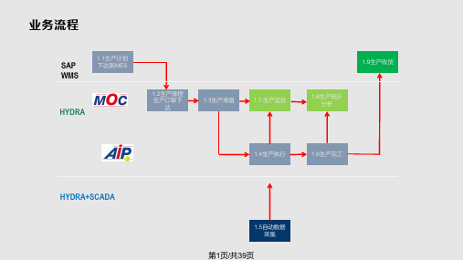
DSS Manager User’s ManualVersion 3.11Table of Contents1OVERVIEW AND ENVIRONMENT (1)1.1Overview (1)1.2System (1)1.3Requirement for Configuration (3)2PROCEDURE OF CONFIGURATION (4)3LOGIN SYSTEM (5)3.1Login Interface (5)3.2Buttons (6)4SYSTEM SETTINGS (7)5MANAGE DEVICE (10)5.1Add Organization (10)5.2Add Device (14)5.2.1Add Encoder (14)5.2.2Add Decoder (19)5.2.3Add Video Wall (20)5.2.4Add Alarm Host (20)5.2.5Add ANPR Device (20)5.2.6Add Intelligent Device (20)5.2.7Add Matrix (21)5.2.8Add A&C (21)5.2.9Add Transcoder (21)5.3Manage Channel (21)6MANAGE ACCOUNT (22)6.1Add User Role (22)6.2Add User (24)7SERVER MANAGEMENT (27)8DAILY OPERATION (29)8.1Add Normal Plan (29)8.2Alarm (33)8.2.1Set Contacts (33)8.2.2Set Link Level (34)8.2.3Set Alarm Time Template (35)8.2.4Set Alarm Storm (36)8.2.5Set Alarm Video on Wall (37)8.3Map (40)8.4Set TV Wall (42)8.5Door Timeout Setup (45)8.6Resources Binding (45)8.7Video Diagnosis (46)8.7.1Diagnosis Item (47)8.7.2Diagnosis Task (48)8.7.3Diagnosis Scheme (49)8.8Config Intelligent Traffic (50)8.8.1Configure ANPR Point (50)8.8.2Configure ANPR Region (51)8.9Set Cascading (52)8.10Upload (53)8.11Backup and Restore (53)8.11.1System Backup (53)8.11.2Restore (54)8.12Resource Re-Config (54)8.12.1Video Server (54)8.12.2Picture Server (55)8.12.3Parameter Re-Config (55)8.13Statistics (55)8.13.1Overview (55)8.13.2Server (58)8.13.3Device (59)8.13.4Management (60)8.13.5Operator (61)8.13.6User Count (61)WelcomeThank you for using our Digital Surveillance System (DSS)!This user’s manual is designed to be a reference tool for operation of your system. Here you can find detailed operation information about DSS.1Overview and Environment1.1OverviewDSS is a hard & software device with Linux structure. It is based on network to connects those decentral and independent on-site monitoring thus achieving centralized monitoring and management crossing area and industry. It provides user with a brand new, direct management tool. Besides A/V, alarm, remote collection, transmission, storage, processing, DSS has advantages of high quality, wide coverage, multi-task, integrable, easy management, one-stop service.●Advanced All-In-One structureUsing leading All-In-One architecture, integrated within DSS series of main control,forwarding, storage, device management and all other functions, eliminates the need for proprietary forwarding servers, storage servers, so that the system set up more convenient.●Real UPnPJust plug it in, configure IP address, DSS series can immediately start working.●One-key upgradeFor subsequent software version upgrade, support network or USB disk one-key upgrade, and make sure that data will not be lost, and the business will not stop.●Higher performanceOne unit DSS series forwarding capacity max 1000Mbit/s, storage capacity max 700 Mbit/s.●Higher securityDSS series supports anti-virus, anti-hacker attack.●Higher stability⏹Forced system power 500 times without exception⏹using self-developed technology and unique new storage disk format⏹provides long-term storage and playback performance decay⏹support hot-swap of storage disk●Higher reliability⏹ support network redundancy⏹Database double-click hot spare1.2SystemThe system network is in Figure 1- 1.Figure 1- 11.3Requirement for ConfigurationChart 1- 12Procedure of ConfigurationYou can refer to the following figure of procedures to configure DSS’s operation. See Figure 2- 1.Figure 2- 13Login System3.1Login InterfaceYou can refer to the following steps to login DSS manager.Step 1. In Internet Explorer, input IP address of DSS, press Enter. You will see Figure 3- 1.Figure 3- 1Note:You can download DSS Client on this login page. If it is your first time login DSS Manager, please add its IP address into the trusted site of your explorer.Step 2. Input Username and Password. Default username is: system. Default password is:123456.For security reason, please change your login password after you first login. Password can contains number, letter, underline and other symbols.Step 3. Click Login.After login, you will see Figure 3- 2.Figure 3- 2Note:●When you exit the system, click Exit in the upper-right corner. Click OK in the prompt box.●If you want to change password, click, and select Modify Password. You can changepassword in the prompt box.3.2Buttons4 System SettingsWhen you first login the system, you shall configure system settings in order to make the system run properly.Configure the system as follows:Step 1. Select System > Parameters, you will see Figure 4- 1.Figure 4- 1Step 2. Configure parameters. Step 3. Click Submit.5Manage DeviceDSS supports adding organization and different types of device.5.1Add OrganizationBefore you add device, you need to add organization of current device. You can arrange, organize and manage layer of device in Org.The default first-level organization is root node. Newly added organization will be displayed below the root node.●Select General> Org, see Figure 5- 1.Figure 5- 1●Click . System pops up a Edit Org box, see Figure 5- 2.Figure 5- 2Step 1. Edit Org Name, and click OK.Step 2. Click . System pops up an Add Org box, see Figure 5- 3.Figure 5- 3Step 3. You can enter designated Org Name and click OK. For multiple layers of organizations, you shall repeat these steps. See Figure 5- 4.Figure 5- 4Note:You can only edit root node and the organization cannot be deleted.Select Org> Logic Org, click . System shows new loggic org box, see Figure 5- 5.Figure 5- 5Step 1. Enter organization name, and click OK.Step 2. On the left, select logic org and click , select setup. See Figure 5- 6.You also can double click login org on the left, and there will be root node shown below.Figure 5- 6You cn adjust channel position with , , , .Step 3. In config channel area, select alternate channel and add it to selected channel. SeeFigure 5- 7.Figure 5- 7You can adjust channel position via , , , buttons.Step 4. Add user. Please refer to Ch 6.1.Note:In Figure 6-1, on the left, select logic org for device tree display.Step 5. Add role. Please refer to Ch 6.2. After configuration is complete, you can login with theadded user account. Click on General area to view. See Figure 5- 8.Figure 5- 85.2Add DeviceYou can add device in two ways:●Device: Manage in device mode, where you can add, edit and delete devices, also you canconfigure and manage deployed devices.●Ch annel: Manage in channel mode there you can view all devices’ monitoring spot andalarm channel.5.2.1 Add EncoderDSS Manager supports manually adding encoder and auto search deployed encoder.●Manually AddStep 1. Select General>Device>Device, system displays device interface.Step 2. ClickStep 3. Click . System displays Add Encoder box, see Figure 5- 9.Figure 5- 9Step 4. Set Input Info, and click Getting Info. System will automatically get info of video channel, alarm input channel and alarm output channel.Note: If you add device with IP section, domain name or auto register, then you cannot get info of video channel, alarm input channel and alarm output channel by clicking on Getting Info.Step 5. Click OK as finishing adding encoder.●Auto SearchSystem automatically adds encoder as follows:Step 1. Click . System auto searches the device and the result shall look like Figure 5- 10.Figure 5- 10●Click to edit device info.●Enter IP address in IP field and click Search to search IP within the range.Step 2. Check device to add, and click .System pops up a Add Encoder box, seeFigure 5- 11.Figure 5- 11Step 3. Select Org, input username and password. Username and password is the login username and password of device. Default username and password is admin/admin.Step 4. Click OK.When device status switches from to as in Figure 5- 12. You also can view added device by selecting Controlled Status in the upper-right corner in Auto Search Encoder interface.Figure 5- 12Step 5. Click Close.System will add the device into corresponding organizations. You may also edit and delete added device, please refer Ch 3.2.5.2.2 Add DecoderDSS Manager supports manually adding decoder and auto search deployed decoder. Please refer to Ch 5.2.1.When you add decoder, please refer to Chart 5- 1.Chart 5- 15.2.3 Add Video WallDSS Manager supports adding of video wall. Please refer to Ch 5.2.1.5.2.4 Add Alarm HostDSS support manually adding of alarm host. Please refer to Ch 5.2.1.5.2.5 Add ANPR DeviceDSS supports manually adding of ANPR device. Please refer to Ch 5.2.1.5.2.6 Add Intelligent DeviceDSS Manager supports manually adding of intelligent device. Please refer to Ch 5.2.1. Step 1. Add IVS device.Step 2. Download and install IVS control.1. Click in IVS device Operation column. If you have no installed IVS control, systemwill pop up a message and ask you to download it and re-login the platform.2. Click OK. System pops up download box.3. Click Save.4. When downloading is complete, click Close.5. Open the downloaded file and install IvsConfigCtrl_Setup.exe.6. Log in IVS interface again.Step 3. Bind video channel to IVS device.1. Click Add.2. Double click device on the left and select channel and select IVS channel on the right.Click . System will bind video channel and IVS channel.3. Check IVS analysis, configure device name, device port and select strea,.4. Click OK. System says successfully saved.5. Click OK.Step 4. Click in Config column to configure rule.●Detection zone: By drawing detection zone, it will detects the entire drawn zone. It will notdetect areas outside the detection zone. There is only one detection zone. You can set more than one excluded zone. If no detection zone is set, it will detect the entire area.●Scene mark: By drawing mark zone and set actual distance for vertical length and horizontallength. Event detector will decide road length and width with a series of algorithm and detect over speed, under speed and etc.●Target filter: Set size or dimension of target and only reserves target within range.●Rule config: Config alarm rule. You can add multiple rules to one channel. Rule type:perimeter protection, tripwire and etc.●Parame ter config: Config jitter rate, sensitivity and etc. Please refer to IVS user’smanual.5.2.7 Add MatrixDSS Manager supports manually adding of matrix device. Please refer to Ch 5.2.1.5.2.8 Add A&CDSS supports manually adding of A&C. Please refer to Ch 5.2.1.5.2.9 Add TranscoderDSS Manager supports manually adding of transcoder. Please refer to Ch 5.2.1.5.3Manage ChannelIn Channel, you can view added video channel, alarm input channel and alarm output channel. You can search added channel in Video Channel interface.Alarm Channel includes alarm input and output channels. You can search added channels here.6Manage AccountDSS Manager allows user to add and delete accounts. User must create user role before adding user. Existing user can login manager and login the client. Different users may have different operation rights according to their user role.6.1Add User RoleBefore you configure user, you must set user role and grand certain rights to the role.Rights of user role includes Administrator Menu right, Operator Menu right and Device right. You must grand these rights before operate.For example, you want to grant right as administrator:Step 1. Click General>Account. System displays Account interface.Step 2. Click Role tab.Step 3. Click . System pops up Add Role box.Step 4. Input Role Name, and select Role Level.Note: If you check Copy Role next to Role Name, and select one role from the dropdown box, then the info will be pasted to your selected role.Step 5. Click Device Rights page, select right in Right Trees and select channel in Channel Tree on the right. See Figure 6- 1.Figure 6- 1Note:●Click so you can copy setting from the selected node to current node.●If you do not check corresponding device right, then all users under this role will have nocorresponding rights.●You must add TV wall in Business>TV Wall before set right of TV wall. Please refer to fontcolor in “0 video input” device.●Red: the channel has not configured on map.●Grey: the channel is added on map.Step 6. Drag device under ANPR input, A&C input and alarm input onto map.Step 7. Complete config of e-map.●Config video wall.Step 8. Click System Rights tag, select corresponding system rights. See Figure 6- 2.Figure 6- 2Note:●If you do not check corresponding device right, then all users under this role will have nocorresponding rights. For example, if Operator Menu is not checked, then when this user logs in Operator, there will be no menu displayed.●Operator menu in system right means C/S and B/S format menu in Client.Step 9. Click OK to add the role.6.2Add UserIf you have added user role, now you can add user of that role.Step 1. Click User tab under Account.Step 2. Click . System pops up Add User box.Step 3. Create a username, a password and confirm password. Select Department and Role.See Figure 6- 3.Figure 6- 3Note:●If you check Reusable box next to Username, then you allows more than one user to loginsystem with this Username at the same time.●If you do not select a role, then the user will have no System Rights or Device Rights.●You can select more than one role at a time.●You can click Optional in the lower-left corner to fill in extra info.Step 4. Click Optional, system display interface as in Figure 6- 4.Figure 6- 4Step 5. Set parameters. Step 6. Click OK to add user.7Server ManagementDSS series Manager provides server management function. Server management has center unit and video unit.●Center serverHas not added dual hot spare.Step 1. Open General>Server>Center Server, you can see operation status of center server. See Figure 7- 1.Figure 7- 1Step 2. Click , you can view center server’s name, video unit status and picture unit status, server type, IP and status. See Figure 7- 2.Figure 7- 2Add dual hot spare.Please refer to DSS Platform Initialization User’s Manual Ch 2.3.Open General>Server>Center Server, you can see operation status of center server.●Video ServerStep 1. Open General>Server>Video Server, you can see operation status of sub server. See Figure 7- 3.Step 2. Click or , you can edit or delete video server. Click you can enter initialization page.Step 3. Click , you can view each video server name, server type, IP and status.8Daily Operation8.1Add Normal PlanDSS Manager supports record plan of channel which allow front-end device to record during planned period.System saves record file to network storage server. You can plan the file in General >Playback on Operator-end.Step 1. Select Business>Storage. System displays Storage interface as in Figure 8- 1.Figure 8- 1Step 2. Set record time.a) Click Time Template in the upper-right corner of storage interface. System displays TimeTemplate interface. Default Time Templates are weekend, weekday and 24-hour.b) Click . System pops a Add Time Template box. See Figure 8- 2.Figure 8- 2c) Input Template Name, select cycle period. Set single system, cycle mode and never stop.See Figure 8- 3.Figure 8- 3Note:If you check Copy next to Template Name, and select template in the dropdown list, then youcan copy configured template to current template.d) Click OK.See Figure 8- 4.Figure 8- 4Step 3. Set normal plan.a) Click Normal Plan in the upper right corner of Storage interface. System displays NormalPlan interface.b) Click . System pops up Add Record Plan box. See Figure 8- 5.Figure 8- 5can clickc) Input Plan Name, and select Template, Bit Stream. Check Record Plan. See Figure 8- 6.Figure 8- 6Step 4. Click OK. System displays configured record plan.8.2AlarmDSS Manager supports alarm, including Alarm Scheme, Output Alarm Video to the Wall, Alarm Type, Alarm Time Template, Link Level and Contacts.●Alarm Scheme: set alarm scheme template.●Output Alarm Video to the Wall: Make alarm video display on wall.●Alarm Type: Set system alarm interval and customize alarm as batch.● Alarm Time Template: Set alarm time template.●Link Level: Set alarm link level.●Contacts: Set user who to receive alarm notice.Alarm flow chart is in Figure 8- 7.Figure 8- 78.2.1 Set ContactsWhen you add user into contacts and if the setup of Link Level includes email or sms, then system will send email or sms to the new contact.Step 1. Click Alarm tab. System displays Alarm interface.Step 2. Click .Step 3. Click . System pops up a Add Contacts box. See Figure 8- 8.Figure 8- 8Step 4. Input User Name, ID No., Email and Telephone.Step 5. Click OK.8.2.2 Set Link LevelYou can set Link Level and its corresponding Link Mode as 1 is the highest and 5 is the lowest. Step 1. Click . System pops up an interface as in Figure 8- 9.Figure 8- 9Step 2. Click . See Figure 8- 10.Figure 8- 10Step 3. Set Link Level Name and select Link Mode.Step 4. Click OK.8.2.3 Set Alarm Time TemplateYou can follow these steps:Step 1. Click . System displays time template interface.Step 2. Click Add. System pops up an Add Alarm Time Template box.Step 3. Input Template Name, select cycle period. Set Single Period and link level. See Figure 8-11.Figure 8- 11Note:●If you check the Copy box next to Template Name, then you need to select template in thedropdown box.●You shall set Link Level first before select level here. Please refer to Ch 7.2.2.●Click to set Link Level of other periods.Step 4. Click OK.8.2.4 Set Alarm StormYou can set alarm interval and customized alarm storm as batch.●Set alarm interval as batchStep 1. Click . System displays Alarm Storm interface.Step 2. Select one or more alarm storm, and click . System pops up abox as in Figure 8- 12.Figure 8- 12Step 3. Set Alarm Interval.Note: The interval cannot be over 86400 seconds.Step 4. Click OK.You can click to stop alarm interval as batch.8.2.5 Set Alarm Video on WallNote:You shall configure TV wall before outputting alarm video to the TV wall. Please refer to font color in “0 video input” device list.●Red: the channel has not configured on map.●Grey: the channel is added on map.Step 1. Drag ANPR input, A&C input and alarm input on the right onto map.Step 2. Complete e-map config.Configure Alarm Scheme as follows:Step 1. Click .Step 2. Click . System pops up an Add Alarm Scheme box as in Figure 8- 13.Figure 8- 13Step 3. Input Scheme Name, select template and check Enable.Note: You must configure Alarm Time Template before selecting time template here. To configure Alarm Time Template please refer to Ch 7.2.3.Step 4. Click Next. System displays Alarm Source and Operation interface.Step 5. Click . System displays Add Alarm Source and Link Operation 1 box, seeFigure 8- 14.Figure 8- 14Step 6. In Alarm Source area, select alarm source and its link operation. Alarm source includes device, video channel, alarm input channel, intelligent channel, A&C channel and system. Different alarm source corresponds to different alarm type.Step 7. In Corresponding Link Operation area, select link operation. Link operation includes Record, and TV Wall.●For link operation, if you select record, you shall select video channel under Record tab, andset record time.Note:If you need pre-record, then select device record needed.●When link level is video wall, you shall add alarm video wall task first, before selectingcorresponding video wall in link level. Please refer to Ch 8.2.6.Step 8. Click Save. System prompts a message “Successfully save scheme rule!”.Step 9. Click OK.Step 10. Click Next. System displays Alarm Preview interface as in Figure 8- 15.Figure 8- 15Step 11. Click Finish.When alarm occurs, system performs link operation according to Alarm Scheme settings, and shows alarm info in Statistics>Device>Device Alarm Info.8.3MapDSS Manager supports super map, raster map, google and google offline map. You can add video device onto the map.Note:If there is no electronic map, please refer to DSS Platform Initialization User’s Manual.To add electronic map:Step 1. Select Business>Map.Step 2. Click Add map.Step 3. Select picture you want to add, click submit.Figure 8- 16Step 4. Drag device under Video Device tab onto the right onto the map. See Figure 8- 17Figure 8- 17Color of text in Video Device list:●Red: the channel is not configured on map.●Grey: the channel is shown on map.Step 5. Drag device under Alarm Input tab onto map.Step 6. Click Save.8.4Set TV WallDSS Manager supports configuration of TV wall.After TV wall is configured, you can make video display on TV wall from Client. Please refer to DSS Cl ient User’s Manual’s Ch 5.5.Note: User of Client must have TV wall right in order to configure video display on TV wall.To configure TV wall, please follow:Step 1. Add decoder. Please refer to Ch 5.2.1.Step 2. Select Business>TV Wall, system displays TV Wall interface.Step 3. Click . System pops up a Add TV Wall box, see Figure 8- 18.Figure 8- 18Step 4. Input TV Wall Scheme Name and click to select layout of 1*1, 2*2, 3*3 or 4*4. See Figure 8- 19.You also can click to customize TV wall.Figure 8- 19Note:●Press Ctrl and now you can select more than one screen. Click on the right tocombine selected screens. You can cancel combination by clicking on . Before you combine screens, you must add video wall equipment.●Double click the screen or right-click and select Properties. In the pop-up box, you can setexact position, size and name of screen.●Select a screen, and right click to delete or rename the screen.Step 5. Click Next. System displays Select decode channel interface.Step 6. In Device Tree, select decoder and drag it to corresponding TV wall. See Figure 8- 20.Figure 8- 20Note: Right-click can cancel current binding and rename screen.Step 7. Click Next. System displays Enable interface.Step 8. Check Apply Now.Note: If you do not check Apply Now, then you cannot select this TV wall on Client.Step 9. Click Finish.8.5Door Timeout SetupDSS supports door timeout setup. If door unlock exceeds set threshold, then system links to level alarm.The higher to level, the higher the threshold will be.Step 1. Select Business>Door Timeout Setup.Step 2. Input alarm level name and threshold.Step 3. Click Submit.8.6Resources BindingDSS supports A&C, alarm host and ANPR resources binding.For example, to set A&C.Step 1. Select Business>Resources Binding>Access and Control. Click . See Figure 8- 21.Figure 8- 21Step 2. Select source channel and video channel. Click OK.8.7Video DiagnosisDSS series Manager supports configuration of video diagnosis, including scheme config, task config and diagnosis item config.●Scheme config: configure video diagnosis scheme template.●Task confi: configure video diagnosis task.●Diagnosis item config: configure video diagnosis item.Flow of video diagnosis is shown in Figure 8- 22.。
帮得佳产品演示动作规范手册
帮得佳产品演示原则
1.“三不做”原则
☆信心不足不做:必须事先做好充分演练准备,并要进行模拟演示。
准备不充分或者信心不足,必须再练习,宁可先不做公开演示。
每次正式演示都必须成功。
☆步骤不一不做:一定要完全按照公司提供的演示步骤进行,缺漏一个环节或者改变一个步骤都是决不允许的。
而且所有步骤的前后关联性要清晰明了。
☆表达不清不做:要非常熟悉“帮得佳”产品特性,能清晰介绍有关专业名词,对于演示的道具和手法都需要理解透彻,语言可以生活化,但必须做到表达自如准确。
2.演示注意事项:
演示前的准备:
✧演示工具要准备充足;
✧整洁干净的着装、干净的演示台;
✧同类产品对比演示前要除去对方标记;
✧建议让所有观看者围成一个半圆,靠近演示台,以便清晰直观地看到演示结果。
但也不宜太近,以免干扰演示操作;
✧灯光尽可能明亮些,活动场地要清洁干净,尽量收走烟灰缸,保持通风(可喷空气清新剂);
✧在演示的主桌上铺上一块干净的白布,做吸水和装饰用;主桌旁安置一张副桌,用来陈列演示要用到的示范工具和产品。
主桌旁要有清洁用的水源。
✧将帮得佳产品摆在演示桌的显眼位置,以便给观看者一定欲了解产品的视觉冲击;
✧将对照品尽可能放在不起眼的地方,等到需要演示或演示正式开始后再取出展示,以免演示前造成观看者不必要的议论和反感;
✧工具器皿要保持清洁,最好事先用盖子盖好;
✧将演示产品品牌正面面向朋友,并保持外观美观清洁;
✧如在家中举办,要提醒朋友让儿童和宠物尽量不要接触产品。
第 1 页共15页
演示过程中:
✧注意介绍产品特点和本次演示的重点;
✧注意演示工具和产品的摆放;
✧不能攻击同行业其他产品;
✧注意演示说辞的前后逻辑性,并称对照样品为“同类产品”;
✧注意对动作的说明;
✧注意放下产品再拿工具;
✧切忌信口开河,夸大产品功效;
✧演示结束前都不要让现场观众触碰演示工具;
✧演示过程中时刻保持用具清洁,多准备一些洁白的抹布或纸巾;合理安排演示工具的使用,特别是演示瓶。
✧作产品示范解说时,要和观众进行眼神交流,可走进新朋友,鼓励他们参与示范、操作体验;
演示结束后:
✧当一个演示结束后,尽量预留1 – 2分钟给观看者体验效果和提问,同时请主持人帮助清洗演示工具;
✧注意彻底的清洗演示工具,特别是演示瓶及瓶盖;
第 2 页共15页
一、单款产品演示
1.净亮洗洁精(浓缩型)
演示目的:与市场上常见洗洁精比较酸碱性
演示工具:
第 3 页共15页
“净亮五环”——演示步骤:
第 4 页共15页
第 5 页共15页
2.超浓缩净柔洁衣液
演示目的:与市场上常见洗衣粉对比溶解度、温和性、无残留性
演示工具:
、
第 6 页共15页
“净柔十全十美”——演示步骤:
第 7 页共15页
第 8 页共15页
第 9 页共15页
第 10 页共15页
3.衣物顽渍预洁剂(浓缩型)
演示目的:去污力说明
演示工具:
第 11 页共15页
“预洁六步”——演示步骤:
第 12 页共15页
第 13 页共15页
四、同类产品对比演示
演示一:与同行业公司产品对比温和性
操作步骤
1. 向大家展示净柔洁衣液
2. 向大家展示它牌洗衣液
3. 向大家展示红石蕊试纸
4. 平铺一张白纸
5. 取适量净柔洁衣液和它牌洗衣液
6. 用红石蕊试纸检测它牌洗衣液
7. 用红石蕊试纸检测净柔洁衣液
8. 效果总结
☆指出净柔洁衣液为弱酸性洗涤剂,温和不伤肌肤
☆指出同类公司洗衣液的确为碱性洗涤剂,经常使用易破坏皮肤的弱酸性环境,引起瘙痒等不适
演示二:与同行业公司产品对比溶解度
操作步骤
1.向大家展示净柔洁衣液
第 14 页共15页
2.向大家展示它牌洗衣液
3.取适量净柔洁衣液
4.取适量它牌洗衣液
5.向大家展示红墨水
6.用墨水将净柔洁衣液和同行业公司洗衣液染色
7.向1#和2#演示瓶加入清水
8.向大家展示1#和2#演示瓶中的溶液
9.效果总结
☆向大家展示净柔洁衣液已经充分溶解在水中,瓶中形成均匀的红色溶液。
☆向大家展示同类公司洗衣液溶液明显有大量油状悬浮物。
指出同类公司洗衣液确实是溶解性较差。
说明这样溶解度差的洗衣液极易在衣物上面残留,不易被清洗干净,残留在衣物上面的
洗涤剂成分会一起人体皮肤不适。
演示三:不损伤衣物比较
操作步骤
1.向大家展示衣物顽渍预洁剂
2.向大家展示它牌预洗洁衣液
3.向大家展示纱布并放在托盘内
4.向左边托盘内的纱布喷洒衣物顽渍预洁剂
5.向右边托盘内的纱布喷洒它牌预洗洁衣液
6.将两块纱布静置1分钟,并向两个演示瓶中分别注入半瓶清水
7.将两块纱布分别放入两个演示瓶中
8.分别搅拌两个演示瓶中的溶液
9.用镊子分别将两个演示瓶中的纱布取出来,并放在托盘内向大家展示
10.效果总结
☆指出使用过同类公司产品后纱布明显有被腐蚀迹象,并有白色碎屑附着;而使用预洁的纱布完好并清洁如新。
☆指出同类公司的产品在分解污垢时会腐蚀衣物,令衣物破损起毛。
同时在水中造成沉淀物,极易对清洗中的衣物造成污垢附着,形成二次污染。
指出我司产品能够温和分解污垢,不损伤衣物,不会造成污垢沉淀,有效避免二次污染。
第 15 页共15页。