ISGB便拆立式多级管道离心泵详细说明书
- 格式:docx
- 大小:574.48 KB
- 文档页数:5
立式多级离心泵技术要求首先是泵的设计原则。
立式多级离心泵的设计应符合流体力学原理,具有合理的流道设计、适宜的叶片形状和角度以及正确的叶轮安装间隙等。
尤其是在多级叶轮设计时,应合理确定各级叶片数目、叶轮直径、流道宽度和轴向间隙等参数,以提高泵的效率和性能。
其次是泵的材料选择。
立式多级离心泵工作环境一般较为复杂,介质可能含有腐蚀性物质、高温或低温介质等,因此要选择适合的材料以保证泵的耐腐蚀性、耐磨性和耐高温性。
常用的材料有不锈钢、镍基合金等,对于特殊工况下的泵,还需要进行防腐处理或涂层加工。
再者是泵的尺寸和重量限制。
立式多级离心泵一般是垂直布置的,需要安装在固定的基座上进行运行。
因此,泵的尺寸和重量要满足现场布置的要求,同时要考虑到方便维护和检修的需要。
在设计过程中,应充分考虑泵的轴向和径向尺寸,以保证泵能够顺利安装并具有稳定的运行性能。
此外,还有泵的密封和冷却系统的设计。
由于立式多级离心泵运行时需要对介质进行密封,因此泵的密封系统设计尤为重要。
常用的密封方式有填料密封、机械密封等,需要根据介质特性和工艺要求进行选择。
同时,为了保证泵的稳定工作,还需要设计合适的冷却系统,以控制泵的温度,避免泵的轴承和密封部件过热。
最后,是泵的运行可靠性和维护性。
立式多级离心泵在运行中需要具有可靠的性能和操作特性,能够保证长时间的连续运行。
同时,由于泵的密封和轴承等部件容易磨损,需要进行定期的维护和保养,因此泵的维护性设计也是一个重要的技术要求。
总之,立式多级离心泵的技术要求包括泵的设计原则、材料选择、尺寸和重量限制、密封和冷却系统设计以及运行可靠性和维护性等方面。
只有在满足这些要求的基础上,才能够设计出高效、安全、可靠的立式多级离心泵,满足不同工况下的需求。
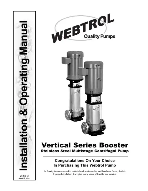
I n s t a l l a t i o n & O p e r a t i n g M a n u a lVertical Series BoosterStainless Steel Multistage Centrifugal PumpCongratulations On Your Choice In Purchasing This Webtrol PumpIts Quality is unsurpassed in material and workmanship and has been factory tested.If properly installed, it will give many years of trouble free service.25ISB-M 9/06 EditionIntroduction2 General Information and Warnings2 Specifications3 Sectional View4 Sectional View - Legend5 Parts Breakdown- Per Pump5 Pump Checks6 Installation6 Operation7 Motor Installation7 Motor Removal8 Disassembly Of Pump9 Mechanical Seal Replacement10 Replacement Of Pump Hydraulic Assembly10Caution:The V Series pumps with motor installed tend to be top heavy, care should be taken in handling and transporting to prevent damage or injury caused by the pump falling over.Caution:Be careful not to exceed the given specifications in the use of your products.Liquid Handled:Type of Liquid Clean WaterTemperature5° to +248°F (-15° to 120°C)Working pressure 230/360 PSI (16/25 Bar)Construction:Impeller Closed Centrifugal SealMechanical Shaft SealPump Bearing Sealed Ball Bearing / Tungsten Carbide Suction/DischargeANSI 250 Lb. 1 1/4” - 4 / 2” - 8 bolt flangeMaterials:See Sectional View Parts List Motor:NEMA C / TC FrameSpeed: 60 Hz, 3450 RPM (2 Poles)3H ftH mExamine the components carefully to ensure that no damage has occurred to the pump or motor during ship-ment. Report damage immediately to the shipping carrier or to your dealer. The Webtrol Vertical Series pump should remain in the shipping carton until it is ready to be installed. Do not drop or mishandle the pump prior to installation.Always check the pump label against the requirement to make sure you are installing the proper pump specified for the job.Make sure that the pump suction, marked by a sticker, is connected to the liquid source and that the discharge, similarly marked, is connected to the discharge line.Caution:On three phase motor installations, always check for proper motor rotation prior to starting by jogging the motor. Shaft rotation must turn clockwise when viewed from back of the motor.Make sure the motor is correctly wired, refer to instructions on motor name plate.Make sure that the pump base is firmly secured to a solid flat surface and that the suction and discharge lines are aligned and properly supported to prevent pipe strain on the pump.where necessary.Using a funnel, fill the pump body with water until it overflows and replace plug.Alternatively for installations with positive suction heads, close the discharge valve and remove the vent plug. Open the suction valve until liquid flows out the vent plug opening and then replace the vent plug securely and open discharge valve.Caution:Extreme caution should be used if priming the pump in this manner in a hot water application. Replace the coupling guards if previously removed.Warning:Operating the pump without the coupling guards in place can cause physical injury.It is recommended that a bleed valve be installed in the discharge line, or in a line from the vent port to the reservoir. This will allow the pressure in the pump to be relieved for service.Installing a bleed valve is especially necessary in hot water application to prevent injury.Pipe, valves and fittings must have a pressure rating equal to or greater than the maximum system pressure.A bypass or pressure relief valve should be installed in the discharge line if there is any possibility the pump may operate against a closed valve in the discharge line.Minimum flow is required for proper cooling and lubrication of the pump without which, damage and premature failure will occur.3. Position the motor, shaft down, about 1” above the pump assembly. Check the motor for balance and align-ment.4. Ensure that the motor key has been placed firmly into the motor shaft keyway.5. Align the motor key and keyway with the coupling keyway and slowly lower the motor into position ensuring that the key slides into the coupling keyway.6. Prior to lowering the motor completely, rotate the motor so that the mounting holes are aligned with the corre-sponding holes in the pump bracket. After alignment, lower the motor onto the pump head.7. Insert the four motor bolts with lock washers and tighten evenly using an alternating criss cross pattern. Tighten the set screws in the coupling.8. Replace the coupling protection guards.Installation procedures for the following pump models:V10B2S - V10B7S, V20B2S - V20B7S, V40B2S - V40B3S1. Make sure the motor protection guard is removed from the pump end.2. Carefully loosen the screws on the coupling and place motor key in the motor shaft keyway.3. Position the motor vertically over the pump with the keyways lined up on the motor shaft and coupling. Then lower the motor into place.4. With the motor positioned over the pump and the motor shaft correctly inserted in the coupling, rotate the motor so that the mounting bolt holes line up with the corresponding holes in the motor bracket. Insert the mounting bolts with lockwashers and firmly tighten using a criss crossing pattern.Warning:When lifting the pump, use appropriate crane (or hoist), check position and tightness of lift system so that weight of the pump is not unbalanced.Failure to observe this precaution can result in serious accidents.1. Remove the motor as detailed in (Motor Removal) section.2. Isolate the pump by closing the suction inlet and discharge valves.3. Carefully relieve the pressure in the pump by opening the vent or drain plugs.4. Remove the vent plug5. Remove the coupling guards with a Phillips head screwdriver.6. Using an Allen wrench (a T-handle is recommended) loosen and remove the pump coupling bolts and remove the lower coupling section.7. Using 900 snap ring pliers, engage coupling snap ring and lift up to clear end of the pump shaft.8. Loosen and remove the four tie rods.9. Rotate the tie rods counter clockwise to loosen from pump base and remove. This will allow the solid coupling to clear the end of the shaft.10. Gently tap the base of the motor bracket with a soft mallet to loosen the fit on the pump assembly.11. Turn the solid coupling half so that it is aligned with the vent pipe.12. Lift the motor bracket off of the pump assembly by tilting the bracket towards the vent pipe and lifting.13. Remove and retain the pump shaft key.14. Remove the seal plate (casing cover) vertically off of the pump shaft assembly.Caution:Extreme caution should be exercised in this operation since the pump is under system pressure at this point. Use a pressure bleed valve in hot water applications where water temperature could cause physical injury.Pump BaseMechanical Seal Replacement1. Complete disassembly of pump as detailed in previous section.2. Remove the old rotating seal assembly by lifting vertically off the pump shaft. The rotating assembly is rubber boot mounted.3. Press the old stationary seal assembly out of the seal plate from the outside of the seal plate. The stationary seat is rubber cup mounted.4. Place the rotating seal assembly retainer onto the shaft taking care not to scratch or touch the seal face. If touching the seal face in necessary, gently wipe with a clean soft tissue.5. Carefully place the rotating seal assembly onto the shaft using a non-metallic sleeve to push the assembly into place on the shaft, seating the rubber boot snugly.6. Using a non-metallic sleeve, press the stationary seal assembly into the seal plate evenly, seating the rubber boot snugly.7. Reassemble the pump as instructed in (Replacement of Pump Hydraulic Assembly) section.Replacement Of Pump Hydraulic Assembly1. Remove the old mechanical seal assembly, refer to “Disassembly of Pump for Mechanical Seal Replacement”.2. Remove the pump body from the pump casing and remove the o-ring located in the pump casing.3. Ensure that the proper replacement hydraulic (stack) assembly has been selected and provided for the appli-cable pump size.4. Lift the replacement hydraulic (stack) assembly and place it onto the pump casing ensuring that it is firmly seated. Ensure that the pump shaft keyway is aligned vertically with the drain connection on the pump casing for ease of later assembly completion.5. Using a new lower pump body o-ring, apply a light film of silicone grease to the o-ring and place it over the hydraulic assembly and into the pump casing ensuring that it is seated.6. Place the pump body onto the entire assembly and align it with the o-ring installed into the pump casing.7. Using new upper pump body lower o-ring, apply a light film of silicone grease to the o-ring and place it into the o-ring groove on the upper pump body ensuring that it is seated.8. Replace the rotating mechanical seal and seal assembly. Refer to “Mechanical Seal Replacement”9. Replace the stationary mechanical seal Assembly. Refer to “Mechanical Seal Replacement”10. Carefully place the seal plate over the pump shaft Be sure the seal face is not damaged during assembly (cracked, scratched, or chipped) or the seal will leak. Ensure that the vent pipe is vertically aligned with the drain connection of the pump casing.11. Install the pump shaft key into the keyway.12. Place the motor bracket onto the pump seal cover by tilting the assembly over the vent pipe. The solid cou-pling half must be turned toward the vent pipe to ensure that the pump shaft hey will slide into the coupling key-way. The motor bracket should fit snugly onto the stationary seal assembly.13. Replace four tie rods, threading them into the pump mounting base.14. Replace the tie rod washers and nuts onto the tie rods finger tight.15. Commence staggered tightening of the tie rod nuts to ensure even distribution of pressure and proper seat-ing of the seal cover plate onto pump body. Tighten all nuts to fit snugly.16. Place handle of soft mallet, or similar lever, into the pump suction so that the entire shaft may be raised slightly until the snap ring groove is above the lower lip of the pump coupling.17. With the pump shaft assembly lifted slightly, replace the pump shaft snap ring or until seated into the groove at the end of the shaft. This will lock the pump shaft into the coupling.18. Replace the lower coupling half and insert coupling bolts tightening them firmly. Ensure that coupling bolts are tightened evenly.19. Replace coupling guards and fasten with coupling guard screws tightening them evenly.20. Reinstall vent pipe plug.21. For reassembly of motor, refer to “Motor Installation”.We at Webtrol are constantly working on new products to make your job easier, while making your systems more efficient, reliable and affordable.Your opinion means a lot to us, so please let us know what you think about our Vertical Series Pump.Weber Industries, Inc. / Manufacturers of Webtrol Products8417 New Hampshire Ave. / St. Louis, MO 63123Phone:(314) 631-9200 Fax:(314) 631-3738 E-mail:********************。
LG、LG-B立式多级泵安装使用说明书LG、LG-B立式多级泵安装使用说明书1、安装前应检验有没有杂质在泵流道内。
2、LG、LG-B型立式多级泵安装位置应尽可能靠近水源处。
3、LG、LG-B型立式多级泵与底座安装有两种方法, 一个直接装在水泥基础上刚性连接, 另一个是采取JGD型减振器安装柔性连接, 具体方法见安装示意图所表示。
4、直接安装中将泵放在基础上垫高30~40毫米(准备充填水泥浆之用), 然后进行校正, 并穿好地脚螺栓, 充填水泥砂浆, 经3~5开水泥干涸后, 重新校正, 待水泥完全干涸后, 拧紧地脚螺栓螺母。
5、安装管路时, 进、出水管路都应有各自支承, 不应使LG、LG-B型立式多级泵法兰承受过大管路重量。
6、LG、LG-B型立式多级泵用于有吸程场所, 进水管端应装有底阀, 而且进口管路不应有过多弯道。
同时不得有漏水、漏气现象存在7、在进口管路上最好装在过滤网, 以防杂质进入叶轮内部。
滤网有交面积应是进水管面积3~4倍, 以确保液体自由通畅。
8、为了维护和使用方便安全, 在泵进口管路上安装一只球阀和在泵出口周围安装一只压力表, 并在压力表前面安装一只自位阀(防水锤), 以确保泵在额定范围内运行, 确保泵正常运行和使用寿命。
9、进口如需扩径连接, 请选择偏心异径管道接头。
使用说明:一、起动1、LG、LG-B型立式多级泵用于有吸程场所, 即进口为负压时, 应先向进口路中进行灌水排气或用真空泵引水, 使水充满整个泵和进口管路, 注意进口管路必需密封, 不得有漏气现象存在。
2、关闭出口管上闸阀及压力计旋塞, 以减小起动电流。
3、用手转动转子几圈, 使轴承润滑并检验泵内叶轮和密封环动转有没有碰擦, 如转不动, 不应起动, 直至找出故障原因为止。
4、试起动, 电机转向应和泵上箭头指向一致, 打开压力计旋塞。
5、当转子达成正常运转后, 压力计显示出压力时, 逐步打开出口闸阀, 调整至所需工况。
二、运转1、LG、LG-B型立式多级泵在运转时, 必需注意观察仪表读数, 尽可能使泵在铭牌要求流量扬程周围工作, 严防大流量运行。
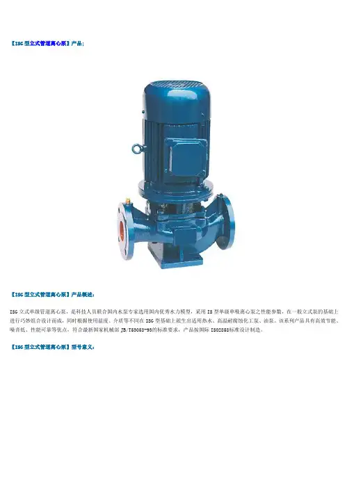
【ISG型立式管道离心泵】产品;【ISG型立式管道离心泵】产品概述:ISG立式单级管道离心泵,是科技人员联合国内水泵专家选用国内优秀水力模型,采用IS型单级单吸离心泵之性能参数,在一般立式泵的基础上进行巧妙组合设计而成,同时根据使用温度、介质等不同在ISG型基础上派生出适用热水、高温耐腐蚀化工泵、油泵。
该系列产品具有高效节能、噪音低、性能可靠等优点,符合最新国家机械部JB/T53058-93的标准要求,产品按国际ISO2858标准设计制造。
【ISG型立式管道离心泵】型号意义:【ISG型立式管道离心泵】产品特点:1、ISG泵为立式结构,进出口口径相同,且们于同一中心线上,可象阀门一样安装于管路之中,外形紧凑美观,占地面积小,建筑投入低,如加上防护罩则可置于户外使用.2、叶轮直接安在电机的加长轴上,轴向尺寸短,结构紧凑,泵与电机轴承配置合理,能有效地平衡泵运转产生的径向和轴向负荷,从而保证了泵的运行平衡振动噪音很低。
3、轴封采用机械密封或机械密封组合,采用进口钛合金密封环、中型耐高温机械密封和采用硬质合金材质,耐磨密封,能有效地增长机械密封的使用寿命。
4、安装检修方便,无需拆动管路系统,只要卸下泵联体座螺母即可抽出全部转子部件。
5、可根据使用要求即流量和扬程的需要采用泵的串、并联运行方式。
6、可根据管路布置的要求采用泵的竖式和横式安装。
【ISG型立式管道离心泵】主要用途:1. ISG立式管道离心泵,供输送清水及物理化学性质类似于清水的其他液体之用,适用于工业和城市给排水、高层建筑增压送水、园林喷灌、消防增压、远距离输送、暖通制冷循环、浴室等冷暖水循环增压及设备配套,使用温度T<80℃。
2. IRG型立式热水泵适用于冶金、化工、纺织、木材加工、造纸以及饭店、浴室、宾馆等锅炉高温热水增压循环输送以及城市住房采暖循环用泵,使用温度120℃以下。
3. GRG型立式高温离心泵广泛用于:能源、冶金、化工、纺织、造纸以及饭店、浴室、宾馆等锅炉高温热水增压循环输送以及城市住房采暖循环用泵,使用温度240℃以下。
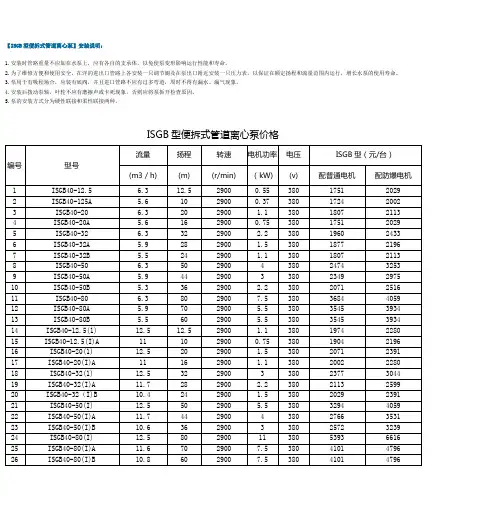
【ISGB型便拆式管道离心泵】安装说明:1.安装时管路重量不应加在水泵上,应有各自的支承体,以免使泵变形影响运行性能和寿命。
2.为了维修方便和使用安全,在洋的进出口管路上各安装一只调节阍及在泵出口附近安装一只压力表,以保证在额定扬程和流量范围内运行,增长水泵的使用寿命。
3.泵用于有吸程场合,应装有底阀,并且进口管路不应有过多弯道,周时不得有漏水、漏气现象。
4.安装后拨动泵轴,叶轮不应有磨擦声或卡死现象,否则应将泵拆开检查原因。
5.泵的安装方式分为硬性联接和柔性联接两种。
ISGB型便拆式管道离心泵价格流量扬程转速电机功率电压ISGB型(元/台)编号型号(m3/h) (m) (r/min) (kW) (v) 配普通电机配防爆电机1 ISGB40-12.5 6.3 12.5 2900 0.55 380 1751 20292 ISGB40-125A 5.6 10 2900 0.37 380 1724 20023 ISGB40-20 6.3 20 2900 1.1 380 1807 21134 ISGB40-20A 5.6 16 2900 0.75 380 1751 20295 ISGB40-32 6.3 32 2900 2.2 380 1960 24336 ISGB40-32A 5.9 28 2900 1.5 380 1877 21967 ISGB40-32B 5.5 24 2900 1.1 380 1807 21138 ISGB40-50 6.3 50 2900 4 380 2474 32539 ISGB40-50A 5.9 44 2900 3 380 2349 297510 ISGB40-50B 5.3 36 2900 2.2 380 2071 251611 ISGB40-80 6.3 80 2900 7.5 380 3684 405912 ISGB40-80A 5.9 70 2900 5.5 380 3545 393413 ISGB40-80B 5.5 60 2900 5.5 380 3545 393414 ISGB40-12.5(1) 12.5 12.5 2900 1.1 380 1974 228015 ISGB40-12.5(I)A 11 10 2900 0.75 380 1904 219616 ISGB40-20(1) 12.5 20 2900 1.5 380 2071 239117 ISGB40-20(I)A 11 16 2900 1.1 380 2002 228018 ISGB40-32(1) 12.5 32 2900 3 380 2377 304419 ISGB40-32(I)A 11.7 28 2900 2.2 380 2113 259920 ISGB40-32(I)B 10.4 24 2900 1.5 380 2029 239121 ISGB40-50(I) 12.5 50 2900 5.5 380 3294 405922 ISGB40-50(I)A 11.7 44 2900 4 380 2766 353123 ISGB40-50(I)B 10.6 36 2900 3 380 2572 323924 ISGB40-80(I) 12.5 80 2900 11 380 5393 661625 ISGB40-80(I)A 11.6 70 2900 7.5 380 4101 479626 ISGB40-80(I)B 10.8 60 2900 7.5 380 4101 479627 ISGB40-80(I)C 10 52 2900 5.5 380 3989 4476流量扬程转速电机功率电压ISGB型(元/台)编号型号(m3/h) (m) (r/min) (kW) (v) 配普通电机配防爆电机28 ISGB50-12.5 12.5 12.5 2900 1.1 380 1974 228029 ISGB50-12.5(I)A 11 10 2900 0.75 380 1918 221030 ISGB50-20 12.5 20 2900 1.5 380 2043 239131 ISGB50-20A 11 16 2900 1.1 380 1974 229432 ISGB50-32 12.5 32 2900 3 380 2363 303033 ISGB50-32A 11.7 28 2900 2.2 380 2113 258534 ISGB50-32B 10.4 22 2900 1.5 380 2029 239135 lSGB50-50 12.5 50 2900 5.5 380 3294 405936 ISGB50-50A 11.7 44 2900 4 380 2780 353137 ISGB50-50B 10.6 38 2900 3 380 2572 325338 ISGB50-80 12.5 80 2900 11 380 5379 661639 ISGB50-80A 11.6 70 2900 7.5 380 4114 479640 ISGB50-80B 10.8 60 2900 7.5 380 4114 479641 ISGB50-80C 10 52 2900 5.5 380 3989 447642 ISGB50-125(1) 25 12.5 2900 1.5 380 2029 239143 ISGB50-12.5(I)A 22.3 10 2900 1.1 380 1974 228044 ISGB50-20(1) 25 20 2900 3 380 2377 303045 ISGB50-20(I)A 22.3 16 2900 2.2 380 2155 264146 ISGB50-32(1) 25 32 2900 4 380 2683 337847 ISGB50-32(I)A 23.4 28 2900 4 380 2683 337848 ISGB50-32(I)B 21.6 24 2900 3 380 2419 287749 lSGB50-50(1) 25 50 2900 7.5 380 3447 428150 ISGB50-50(1)A 23.5 44 2900 7.5 380 3447 428151 ISGB50-50(I)B 21.8 38 2900 5.5 380 3336 400352 ISGB50-80(1) 25 80 2900 15 380 5880 729853 ISGB50-80(I)A 23.4 70 2900 11 380 5546 681154 ISGB50-80(I)B 21.6 60 2900 11 380 5546 681155 ISGB50-125(1) 25 125 2900 30 380 9118 1241356 ISGB50-125(I)A 23.7 113 2900 22 380 7506 9424流量扬程转速电机功率电压ISGB型(元/台)编号型号(m3/h) (m) (r/min) (kW) (v) 配普通电机配防爆电机57 ISGB50-125(I)B 22.5 101 2900 18.5 380 6839 852158 ISGB50-125(I)C 20.6 85 2900 15 380 6491 8006。
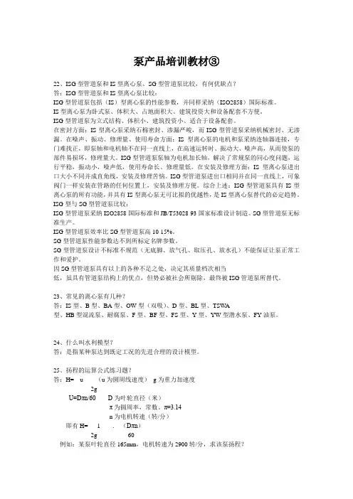
泵产品培训教材③22、ISG型管道泵和IS型离心泵、SG型管道泵比较,有何优缺点?答:ISG型管道泵和IS型离心泵比较:ISG型管道泵包括(IS)型离心泵的性能参数,并同样采纳(ISO2858)国际标准。
IS型离心泵为卧式泵、体积大、占地面积大、建筑投资大和设备配套不方便。
ISG型管道泵为立式结构、体积小、建筑投资小、适合于设备配套。
在密封方面:IS型离心泵采纳石棉密封、渗漏严峻,而ISG型管道泵采纳机械密封、无渗漏。
在噪声、振动、修理量、使用寿命方面:IS型离心泵的电机和泵采纳连轴器连接,专门难找正,即泵轴和电机轴不在同一直线上,在高速运转时、振动大、噪声高,从而使泵的部件易损坏,修理量大。
ISG型管道泵泵轴为电机加长轴,解决了常规泵的同心度问题,运行平稳,振动小,噪声低,使用寿命长、修理量低。
在安装及修理方面:IS型离心泵进出口大小不同并成直角线,安装及修理苦恼。
ISG型管道泵进出口相同并在同一直线上,可象阀门一样安装在管路的任何位置上,安装及修理方便。
综合上述:ISG型管道泵具有IS型离心泵的所有功能,并具有IS型离心泵无可比拟的优越性,是IS型离心泵替代的必定趋势。
ISG型与SG型管道泵比较:ISG型管道泵采纳ISO2858国际标准和JB/T53028-93国家标准设计制造。
SG型管道泵无标准生产。
ISG型管道泵效率比SG型管道泵高10-15%。
SG型管道泵性能参数达不到所标定名牌参数。
SG型管道泵设计不标准不规范(无底脚、放气孔、取压孔、放水孔)不能保证让泵正常工作和爱护。
因SG型管道泵具有以上的各种不足之处,决定其质量档次相当低,虽具有管道泵结构上的优点,但势必被社会所剔除,最终被ISG管道泵所替代。
23、常见的离心泵有几种?答:IS型、B型、BA型、OW型(双吸)、D型、BL型、TSWA型、HB型混流泵、耐腐泵、F型、BF型、FS型、Y型、YW型潜水泵、FY油泵。
24、什么叫水利模型?答:是指某种泵达到既定工况的先进合理的设计模型。
上海沈泉泵阀制造有限公司■ 产品概述ISG 型系列单级单吸管道离心泵,是本单位科技人员联合国内水泵专家选用国内优秀水力模型,采用I S 型离心泵之性能参数,在一般立式泵的基础上进行巧妙组合设计而成,同时根据使用温度、介质等不同在I SG 型基础上派生出适用热水、高温、腐蚀性化工泵、油泵。
该系列产品具有高效节能、噪音低、性能可靠等优点。
符合最新国家机械部J B /T5 3 0 5 8—9 3的标准要求。
产品按国际I S0 2 8 5 8标准设计制造。
9 3年通过国家机械工业部管道泵产品统检合格。
■ 产品特点1.泵为立式结构,进出口口径相同,且位于同一中心线上,可象阀门一样安装于管路之中,外形紧凑美观,占地面积小,建筑投入低,如加上防护罩则可置于户外使用.2.叶轮直接安在电机的加长轴上,轴向尺寸短,结构紧凑,泵与电机轴承配置合理,能有效地平衡泵运转产生的径向和轴向负荷,从而保证了泵的运行平稳,振动噪音很低.3.轴封采用机械密封或机械密封组合,采用进口钛合金密封环、中型耐高温机械密封和采用硬质合金材质,耐磨密封,能有效地增长机械密封的使用寿命。
4.安装检修方便,无需拆动管路系统,只要卸下泵联体座螺母即可抽出全部转子部件。
5.可根据使用要求即流量和扬程的需要采用泵的串、并联运行方式. 6.可根据管路布置的要求采用泵的竖式和横式安装。
■ 型号意义■ 产品用途1.,供输送清水及物理化学性质类似于清水的其他液体之用,适用于工业和城市给排水,高层建筑增压送水,园林喷灌,消防增压,远距离输送,暖通制冷循环。
浴室等冷暖水循环增压及设备配套,使用温度T<8 0℃.2. 泛适用于:能源、冶金、化工、纺织、造纸,以及宾馆饭店等锅炉高温热水增压循环输送及城市采暖系统循环用泵,I RG 型使用温度T<1 2 0℃,GRG 型使用温度T<2 40℃。
3. IHG 型,供输送不含固体颗粒,具有腐蚀性,粘度类似于水的液体,适用于石油、化工、冶金、电力、造纸、食品制药和合成纤维等部门使用温度为-20℃-120℃ .4.YG 型,供输送汽油、煤油、柴油等石油产品,被输送介质温度为-2 0℃-+1 2 0℃。
立式多级离心泵安装使用说明书系列: MVA, MVS代斯米泵业技术有限公司电话: +45 96 32 81 11传真: +45 98 17 54 99邮件: ***************网站: 说明书: T1536 语言:中文版本:A1(03/20)目录1手册说明 (4)1.1前言 (4)1.2图标和符号 (4)2担保 (5)2.1 担保条款 (5)3产品 (6)3.1 产品介绍 (6)3.2 型号说明 (6)3.3 机械密封代号 (6)3.4 额定电流 (7)4安全与环境 (8)4.1通用 (8)4.2用户 (8)4.3安全措施 (8)4.4安全保护措施 (8)4.5环境方面 (9)5用途及使用范围 (10)5.1产品特点 (10)5.2用途 (10)5.3使用范围 (10)5.4工作介质 (10)6技术参数 (11)6.1环境温度 (11)6.2液体温度 (11)6.3最小进口压力的计算方法 (11)6.4压力与温度 (12)6.5电气参数 (12)6.6电机起/停次数 (12)6.7尺寸及重量 (12)6.8噪音等级 (12)7安装及使用前注意事项 (13)7.1安装时请按照以下事项操作,以免损坏泵 (13)7.2启动泵前检查 (14)7.3启动步骤 (15)8性能参数 (16)9保养 (17)10运输储存 (18)10.1运输 (18)10.2存储 (18)11故障解决 (19)12尺寸图 (21)13爆炸图 (29)1 手册说明1.1 前言本手册包含了正确、可靠和有效操作及使用产品的重要信息。
遵守操作说明对于确保产品的可靠性和较长的使用寿命以及避免任何风险都是至关重要的。
本章包含关于本手册和一般安全的信息。
以下章节提供了关于产品的正常使用、安装、维护和修理的信息。
•熟悉手册内容。
•准确地遵循指示和说明。
•按照手册,永远不要改变操作要求的顺序。
•将本手册或本手册的副本放在产品附近的固定位置,以便所有操作人员都能使用。
上海沈泉泵阀制造有限公司☆ 产品简介及特点GDL型多级管道离心泵是我单位在国内外优秀泵型之基础上结合用户的使用要求及消防有关标准,并根据JB/TQ6435-92标准设计制造的新一代产品。
本型泵采用立式节段式外加不锈钢壳体结构,使得泵的进出口位于同一水平线上且口径相同,能象阀门一样安装于管路之中,它同时集中了多级泵之高压,立式泵之占地面积小及管道泵之安装方便的优点,同时由于采用了优秀的水力模型,所以还具有高效节能,运行平稳等优点,且轴封采用耐磨机械密封,无泄漏使用寿命长。
为了能更好地满足用户的要求,本单位还开发了出水口位于上部的GDLS型,其进出口可以不同的相对位置(0°、90°、180°)安装,使用极为方便。
为了使用户能更加安全、可靠的使用该型泵,本单位特别研制了便拆式结构型,它除拥有GDL、GDLS的一切优点外,更为您更换机械密封等易损件提供了更加方便,快捷、省力的途径,使本型泵更无忧运行与维护。
应用范围本型泵主要适用于高压运行系统中冷热清水的循环和增压、高层建筑多台泵并联供水、消防、锅炉给水和冷却水系统及各种冲洗液的输送等。
工作条件1.本型泵可输送清水或物理化学性质类似于清水的液体;2.液体温度:-15℃~+120℃;3.工作压力:最大工作压力<2.5MPa,即系统压力=入口压力+闭阀工作时的压力<2.5MPa;4.周围环境的温度应低于40℃,相对湿度不超过95%;5.输送含腐蚀性介质及热液体时,请于订货时提出,以便采用特殊材质满足使用要求。
☆ 型号意义☆ 结构简图1 泵体 11 联轴器 1 泵体 11联接座 1吸入段 11 联接座2 拉紧螺栓 12 联接座 2 拉紧螺栓 12密封座 2拉紧螺栓 12 密封座3 外筒 13 气嘴 3 外筒 13轴承座 3外筒 13 复合轴承4 叶轮 14 机械密封 4 叶轮 14机械密封 4叶轮 14 轴承座5 时轮挡套 15 轴 5 叶轮挡套 15轴 5叶轮挡套 15 机械密封6 轴套 16 中段 6 轴套 16中段 6密封垫 16 轴7 密封垫 17 轴套螺母 7 密封垫 17轴套螺母 7螺母 17 中段 8 螺母 18 轴瓦 8 螺母 18轴瓦8出水段 18 轴套螺母 9 销 19 回水管部件 9 联轴器 19回水管部件9联轴器 19 轴瓦 10 电机10 电机10电机☆型谱图☆ 性能曲线图25GDL2 25GDL240GDL6 50GDL1250GDL18 65GDL2480GDL36 80GDL54100GDL72 125GDL100150GDL-160☆性能参数表流量功率(KW)型号(m3/h) (L/S) 扬程(m) 效率(%)转速(r/min)轴功率电机功率 汽蚀余量(m) 进出 口径 (mm) 高度 H (m) 重量(kg)高度h1 (m)25GDL2-12×31.4 22.4 0.39 0.56 0.67 38 36 33 23 30 32 2900 0.630.650.67 1.1 1.4 1.7 1.8 25 606 58 12525GDL2-12×41.4 22.4 0.39 0.56 0.67 50 48 44 23 30 32 2900 0.830.870.90 1.1 1.4 1.7 1.8 25 646 62 16525GDL2-12×51.4 22.4 0.39 0.56 0.67 63 60 55 23 30 32 2900 1.041.091.12 1.5 1.4 1.7 1.8 25 711 68 20525GDL2-12×61.4 22.4 0.39 0.56 0.67 76 72 66 23 30 32 2900 1.261.301.35 1.5 1.4 1.7 1.8 25 751 72 245 25GDL2-12×71.4 22.4 0.39 0.56 0.67 88 84 77 23 30 32 2900 1.461.521.57 2.2 1.4 1.7 1.8 25 816 78 28525fiDL2-12×81.4 22.4 0.39 0.56 0.67 101 96 88 23 30 32 2900 1.631.741.80 2.2 1.4 1.7 1.8 25 856 82 32525GDL2-12×91.4 22.4 0.39 0.56 0.67 114 108 99 23 30 32 2900 1.891.962.02 2.2 1.4 1.7 1.8 25 896 86 36525GDL2-12×101.4 22.4 0.39 0.56 0.67 126 120 110 23 30 32 2900 2.012.172.24 3 1.4 1.7 1.8 25 981 98 40525GDL2-12×111.4 22.4 0.39 0.56 0.67 139 132 121 23 30 32 2900 2.312.392.47 3 1.4 1.7 1.8 25 1021 102 44525GDL2-12×121.4 22.40.39 0.56 0.67152 144 13223 30 3229002.522.612.7031.4 1.7 1.825106110648525GDL4-11×3 2.844.80.781.111.33363328.532404129000.860.900.911.11.41.71.825 606 58 12525GDL4-11×4 2.844.80.781.111.3348443832404129001.141.201.211.51.41.71.825 671 65 16525GDL4-11×5 2.844.80.781.111.33605547.532404129001.431.501.512.21.41.71.825 736 72 20525GDL4-11×6 2.844.80.781.111.3372665732404129001.721.801.822.21.41.71.825 776 76 24525GDL4-11×7 2.844.80.781.111.33847766.532404129002.002.102.1231.41.71.825 861 86 28525GDL4-11×8 2.844.80.781.111.3396887632404129002.292.402.4231.41.71.825 901 90 32525GDL4-11×9 2.844.80.781.111.331089985.532404129002.572.702.7331.41.71.825 941 94 36525GDL4-11×10 2.844.80.781.111.331201109532404129002.863.003.0341.41.71.825 1011 110 40525GDL4-11×11 2.844.80.781.111.33132121104.532404129003.143.303.3341.41.71.825 1051 114 44525GDL4-11×12 2.844.80.781.111.3314413211432404129003.433.603.6441.41.71.825 1091 118 48525GDL4-11×13 2.844.80.781.111.33156143123.532404129003.723.903.9441.41.71.825 1131 122525注:1: GDLS、GDL-B、GDLS-B型除重量H尺寸稍有不同外其性能参数与GDL型相同。
多级立式离心泵是一种常用的工业设备,广泛应用于供水、加压输送、供暖、空调等领域。
在使用多级立式离心泵时,需要遵守一定的操作规程和注意事项,以确保设备的安全运行和有效工作。
下面将针对多级立式离心泵的使用说明进行详细介绍。
一、设备介绍1. 多级立式离心泵是一种由进口轴承、轴封、泵体、叶轮等部件组成的泵类设备。
它具有高效节能、流量大、扬程高等特点,适用于中小型工业和民用建筑的供水和水循环系统。
2. 多级立式离心泵可根据用户的需求选择不同的材质,例如不锈钢、铸铁、铜等,以适应不同的工作环境和介质。
3. 设备采用了先进的结构设计和制造工艺,确保了设备的稳定性和可靠性。
多级立式离心泵的安装、使用、维护都比较简便。
二、操作规程1. 在启动多级立式离心泵之前,需要先检查设备的电源接线是否牢固,电机是否正常接地。
2. 启动时,应按照设备的操作说明书操作,以免因操作不当引起损坏或事故。
3. 注意监测设备的电流、电压和运行声音,确保设备的正常运行状态。
三、设备维护1. 定期检查设备的轴承、轴封、叶轮等部件的磨损情况,发现问题及时更换。
2. 维护人员应具备一定的机械和电气知识,能够及时发现和处理设备的故障。
3. 在设备不使用时,需要及时清洗泵体内部的介质并进行防腐处理,以延长设备的使用寿命。
四、安全注意事项1. 在使用多级立式离心泵时,需保持设备周围的清洁和整洁,避免进入异物影响设备的正常工作。
2. 禁止在设备运行中进行维修和保养操作,以免发生危险。
3. 正确操作设备,避免超负荷运行,以免损坏设备和降低设备的寿命。
五、环保要求1. 多级立式离心泵使用过程中,需要注意减少设备的能耗和杜绝泄漏现象。
2. 设备使用寿命结束后,应按照环保要求进行处理,避免对环境造成污染。
六、结语通过以上介绍,我们对多级立式离心泵的使用说明有了更加全面的了解。
在实际操作中,我们需要严格依照设备的说明书和操作规程来进行操作,从而确保设备的正常运行和安全工作。
离心泵的使用说明—详细泵是输送流体或使流体增压的机械。
它将原动机的机械能或其他外部能量传送给液体,使液体能量增加。
泵主要用来输送水、油、酸碱液、乳化液、悬乳液和液态金属等液体,也可输送液、气混合物及含悬浮固体物的液体。
泵通常可按工作原理分为容积式泵、动力式泵和其他类型泵三类。
除按工作原理分类外,还可按其他方法分类和命名。
如,按驱动方法可分为电动泵和水轮泵等;按结构可分为单级泵和多级泵;按用途可分为锅炉给水泵和计量泵等;按输送液体的性质可分为水泵、油泵和泥浆泵等。
按照有无轴结构,可分直线泵,和传统泵。
水泵只能输送以流体为介质的物流,不能输送固体。
第一台离心泵于1705年问世,由于离心泵的应用面极广,目前离心泵已经是主流的泵类产品,占据泵行业大部分市场。
由离心泵演化而来的泵产品多不胜数,离心泵本身也被细化成多种品类离心泵。
最早提离心泵的是法国工程师Papin,他在1689年发明了可以称之为离心泵雏形的一种机器,并于1705年制造了第一台适用于提升液体的泵。
该泵采用了多叶片的叶轮和蜗形体的泵壳。
著名数学家欧拉于1750年对离心泵的流动进行了理论分析,为离心泵的发展奠定了基础。
1818年作为离心泵发展史上一个转折点,在美国的Massachusetts开始批量生产离心泵。
1851年JamesStuartGwynne在英国获得多级离心泵发明专利,英国科学家J.Tomsom 采用导叶来提高泵的效率。
20世纪初,在蒸汽轮机的全盛时期,泵几乎全是往复式的。
1904年KSB公司提供了锅炉给水用高压离心泵的系列,1905年苏尔寿兄弟工厂开始多级串联高压泵的批量生产。
随着机械制造技术和计算机技术的应用,泵在世界各国得到了很大发展。
目前世界上泵产品的种类已达5000多种,其中包括:齿轮泵、IS清水泵、中开泵、多级离心泵等。
泵类产品在大容量、高效率、自动化和可靠性方面达到了新的水平。
在泵的理论研究方面,多采用计算流体力学软件来模拟实际流动和分析流动损失。
一、概述GBL浓硫酸化工泵是根据IG型离心泵之性能参数,采用浓硫酸专用铸铁、碳钢二种材料和优秀水利模型进行优化设计而成。
是理想的新一代化工泵。
二、产品特点1、泵为立式结构,进出口口径相同,且位于同一中心线上,可象阀门一样安装于管路之中,锅炉给水泵外型紧凑美观,占地面积小,建筑投入低,如加上防护罩则可置于户外使用。
2、叶轮直接安装在电机的加长轴上,轴向尺寸短,结构紧凑,泵与电机轴承配置合理,能有效地平衡泵运转产生的径向和轴向负荷,从而保证了泵的运行平稳,振动噪音很低。
3、该泵轴封采用外装式优质机械密封,动、静环采用新型硬质合金和陶瓷制成,耐磨损、无泄漏、使用寿命长。
三、选材依据专用钢铁大量应用于80~100%的硫酸,温度可达60-80℃。
钢铁在这一浓度和温度范围的硫酸中,表面能产生保护性的硫酸铁膜层。
铸铁不适用于超过100%的发烟硫酸,可能是由于三氧化硫与铁中所含的硅反应,使铸铁变脆。
碳钢不适用于 100~102%的发烟硫酸,超过102%的酸则又适用,温度限定约为60℃。
稀硫酸对钢铁的腐蚀很大,当酸浓度为47%左右时,腐蚀率达到最高值。
当酸浓度大于65%时,钢铁的腐蚀率显著降低。
但是在65~80%这一段浓度中,最好还是不使用钢铁,以用铅或其它耐稀酸材料更为安全。
硫酸浓度:80%~98% 专用铸铁使用温度:25℃~50℃硫酸浓度:80%~98% 专用碳钢使用温度:25℃~60℃四、型号意义六、注意事项与维护1、安装前应仔细检查泵体流道内有无硬质物,以免运行时损坏叶轮和泵体2、泵的进、小口1管路上要安装调节阀,以控制泵在额定工况内运行3、打开进口阀门,使液体充满整个泵腔。
4、接通电源,当泵达到正常转速后,再逐渐打开吐出管道上的阀门,并调节到所需的工况。
5、检查电机、轴承处温升≤70℃发现异常及时处理。
6、严禁机械密封在干磨情况下工作作。
概述GENERALLDY型油泵系立式多级离心油泵,用以输送温度为0℃~80℃透平油。
供汽轮机、制氧机以及辅助机械的强制油润滑和液压之用。
主要用于集中油站中输送润滑油。
Model LDY oil pump is a vertical multi-staged centrifugal oil pump. It is used to deliver the turbine oil which the temperature is 0℃--80℃.Provide the steam turbine ,oxygeneratorand assists mechanical oil forcing lubricious the usefulness of the hydraulic pressure.泵型号意义说明举例:The explanation to pump type significance is given an example:例:LDY25-30×3L……立式For example:LDY25-30×3L……The verticalityD……多级D……Multiple stage Y……离心油泵Y……Centrifugal oil pump25……设计点流量25米3/时30……设计点单级扬程30米3……叶轮级数3级25……Capacity(m /h)3 30……Head of stage(m) 3……Number of impeller本系列立式多级离心油泵特点:泵的机体立式布置,泵座法兰安装在集中油站的油箱上面,占地面积少,结构紧凑,重量轻,解决了汽轮机、制氧机、压缩机、多级轴流风机等大型机械装备集中油站油箱上辅助机械以及管路等在安装上的困难;使机房设备布置整齐、美观。
由于泵的叶轮、泵体浸入润滑油中,无须底阀装置,能够顺利地启动油泵;泵的轴承润滑不必外加润滑油,由泵自行解决。
一、工业水泵分类型号大全1、清水泵IS清水泵ISGB便拆清水泵ISW卧式清水泵SG型清水管道泵S.SH双吸泵 YT单吸清水泵 YW漩涡泵 ZX自吸泵 ISG立式清水泵2、热水泵ISR型单吸热水泵IRG型立式热水泵IRGB立式便拆热水泵ISWR卧式热水泵 SGR热水管道泵3、耐腐泵IH化工泵 IHG立式化工泵 IHGB立式便拆化工泵 SGP管道化工泵 DF多化工泵 GDLP多化工泵氟塑料合金泵 FB耐腐蚀泵 AFB单化工泵 IHF氟塑料化工泵 FY耐腐蚀化工泵 FYS氟合金液下泵4、油泵IY单击油泵 AY离心油泵 YG立式油泵 YGB立式便拆热水泵 SGB 管道油泵ISWB卧式油泵WRY热油泵CYZ自吸油泵KCB齿轮油泵2CY双齿轮油泵 2CG高温齿轮油泵多清水泵 D清水多泵MD耐磨多泵 DC锅炉给水泵 DG锅炉给水泵 DL立式多泵 GDL立式多泵 TSWA卧式多泵立式多管道泵5、污水泵AS.AV潜水排污泵WQ无堵塞排污泵WL立式排污泵WY液下排污泵 GW管道排污泵 HW蜗壳混流泵 ZW自吸排污泵 WG污水泵 PW 污水泵 PWL立式污水泵6、杂质浆泵NL立式泥沙泵 NWL立式泥浆泵 YPN卧式泥浆泵 YPNL立式泥浆泵 LXL卧式浆泵 ZJ渣浆泵 ZJM渣浆泵 M.AH.HH渣浆泵 I-1B螺杆浓浆泵7、潜水泵QJ深井潜水泵 QS冲水潜水泵 QY油沁潜水泵8、真空泵SZ.SK水环式真空泵 ZKB真空泵 SZB真空泵 X真空泵9、特种泵CQ磁力驱动泵 CQF塑料磁力驱动泵 CQB不锈钢磁力驱动泵 ZCQ 自吸磁力驱动泵PB屏蔽泵QBY气动隔膜泵DBY电动隔膜泵XBD 消防泵 WFB自控自吸泵 N冷凝泵 NW输水泵二、工业水泵型号代表水泵的构造特点工作性能水泵型号代表水泵的构造特点工作性能和被输送介质的性质等。
由于水泵的品种繁多,规格不,所以型号也较紊乱,这里只列出些常见的水泵型号。
1、BA型泵单单吸悬臂式离心泵,流量为4.5~360m3/h,扬程为8~98米,介质温度在80℃以下。
ISG、IRG、IHG型立式管道离心泵产品概述:博生牌ISG系列单级单吸立式离心泵是本公司参照国际ISO2858和国家标准JB/T6878.2-93所规定的性能参数,结合本公司多年生产经验而设计的第二代高效节能产品,是替代SG型管道离心泵、IS型离心泵、D 型多级离心泵等常规泵的理想产品。
系列流量范围1.5~1600m3/h,扬程范围5~125m,分基本型、分流型、切割型等多种规格。
根据使用场合介质和温度不同,过流部分的材质变化及结构变化,设计制造同性能参数的IRG型热水泵、IHG型管道化工泵、YG型管道油泵、使该系列产品使用得到普及,完全可以替代常规离心泵在所有场合使用。
产品特点:①泵为立式结构,进出口口径相同,且位于同一中心线上,可象阀门一样安装在管路之中,外形紧凑美观,占地面积小,建筑投入低,如加上防护罩则可置于户外使用。
②叶轮直接安装在电机的加长轴上,轴向尺寸短、结构紧凑,泵与电机轴承配置合理,能有效地平衡泵运转产生的径向和轴向负荷,从而保证了泵的运行平稳,振动噪音很低。
③轴封采用机械密封或机械密封组合,采用进口钛合金密封环、中型耐高温机械密封和采用硬质合金才质,耐磨密封,能有效地增长机械密封的使用寿命。
④安装检修方便面,无需拆动管路系统,只要卸下泵联体座螺母即可抽出全部转子部件。
⑤可根据使用要求即流量和扬程的需要采用泵的串、并联运行方式。
⑥可根据管路布置的要求采用泵的竖式和横式安装。
型号意义:使用范围:1、ISG立式离心泵,供输送清水及物理性质似清水的其它液体之用,使用介质温度不超过80℃,适用于工业和城市给排水、高层建筑增压送水、园林喷灌、消防增压、远距离送水、采暖、浴室等冷暖水循环增压及设备配套等。
2、IRG立式热水循环泵,适用于能源、冶金、木材加工、化工、纺织、造纸及饭店、浴室、宾馆等锅炉热水增压循环输送及城市采暖系统循环用泵,使用介质温度不超过120℃。
3、IHG立式化工泵,适用于轻纺、石油、化工、医药、卫生、食品、炼油等工业输送化学腐蚀性液体,介质温度为-20℃~+120℃。
【ISG型立式管道离心泵】使用条件:1、吸入压力≤1.0Mpa,或泵系统最高工作压力≤1.6Mpa,即泵吸入口压力+泵扬程≤1.6Mpa、泵静压试验压力为2.5Mpa,订货时请注明系统工作压力。
泵系统工作压力大于1.6Mpa时应在订货时另行提出。
以便在制造时泵的过流部件和联接部分采用铸钢材料。
2、环境温度<40℃,相对湿度<95%。
3、所输送介质中固体颗粒体积含量不超过单位体积的0.1%,粒度<0.2mm.注:如使用介质为带有细小颗粒,请在订货时说明,以便采用耐磨式机械密封。
ISG、IRG、IHG、YG、IHGB立式、ISW卧式单级单吸管道离心泵价格编号型号规格流量(m³/h)扬程(m)转速(r/min)功率(KW)电压(V)ISG清水IRG热水IHG化工耐腐型YG油泵IHGB耐腐防爆型ISW卧式1 15-80 1.5 8 2800 0.18 220 417 723 / / /2 20-110 2.5 15 2800 0.37 220 500 931 / / /3 20-160 2.5 32 2900 1.1 220 765 1265 / / /4 25-110 4 15 2900 0.55 220 695 1209 1154 / /5 25-125 4 20 2900 0.75 220 737 1265 1140 / /6 25-160 4 32 2900 1.5 220 765 1404 1154 / /7 25-160A 3.7 28 2900 1.1 220 695 1334 1321 / /8 32-100 4.5 12.5 2900 0.55 220 765 1279 1307 / /9 32-100(I) 6.3 12.5 2900 1.1 220 765 1265 1154 / /10 32-125 4.5 20 2900 0.75 220 737 1195 1154 / /11 32-125A 4 16 2900 0.55 220 695 1140 / / /12 32-160 4 32 2900 1.1 220 765 1348 1265 / /13 40-100 6.3 12.5 2900 0.55 220 695 1140 / / /14 40-100A 5.5 8 2900 0.37 220 500 931 / / /15 40-125 6.3 20 2900 1.1 220 765 1334 1251 / /16 40-125A 5.5 16 2900 0.75 220 737 1209 1154 / /17 40-100(I) 12.5 12.5 2900 1.1 220 834 1209 1195 / /18 40-100(I)A 10.5 8 2900 0.75 220 737 1182 / / /19 40-125(I)A 10.5 16 2900 1.1 220 765 1362 1265 / /20 50-100 12.5 12.5 2900 1.1 220 765 1362 1321 / /21 50-100A 12.5 10 2900 0.75 220 737 1265 1168 / /22 50-125A 11.2 17.2 2900 1.1 220 765 1348 1251 / /23 50-100(I)A 22.4 10 2900 1.1 220 765 1404 1279 / /24 65-100A 20 8 2900 1.1 220 765 1390 1279 / /25 20-160 2.5 32 2900 1.1 380 723 1112 1195 1724 86226 25-160A25-160 4 20 2900 0.75 380 695 1084 1154 1724 83427 32-100(I) 4 32 2900 1.5 380 765 1279 1209 1863 90428 32-125 3.7 28 2900 1.1 380 723 1112 1182 1724 862编号型号规格流量(m³/h)扬程(m)转速(r/min)功率(KW)电压(V)ISG清水IRG热水IHG化工耐腐型YG油泵IHGB耐腐防爆型ISW卧式29 32-100(I) 6.3 20 2900 1.1 380 723 1126 1154 1724 86230 32-125 5 20 2900 0.75 380 695 1084 1154 1751 83431 32-125(I) 6.3 20 2900 1.1 380 723 1168 1195 1751 86232 32-160 4.5 32 2900 1.5 380 765 1460 1529 2335 90433 32-160A 4 25 2900 1.1 380 723 1209 1237 1877 86234 32-160(I) 6.3 32 2900 2.2 380 834 1696 1724 2335 97335 32-200 4.5 50 2900 3 380 1182 2057 2085 3253 132136 32-200A 4 40 2900 2.2 380 890 1696 1724 2599 104337 32-200(I) 6.3 50 2900 4 380 1362 2460 2502 3406 152938 40-125 206.3 20 2900 1.1 380 723 1209 1251 1863 86239 40-125A 5.6 16 2900 0.75 380 695 1084 1154 1738 83440 40-160 6.3 32 2900 2.2 380 834 1599 2502 2502 97341 40-160A 5.9 28 2900 1.5 380 765 1501 2335 2335 90442 40-160B 5.2 24 2900 1.1 380 723 1473 1529 2280 86243 40-200 6.3 50 2900 4 380 1362 2446 2502 3711 152944 40-200A 5.9 44 2900 3 380 1154 2113 2446 3253 139045 40-200B 5.5 38 2900 2.2 380 917 1974 1946 3058 111246 40-250 6.3 80 2900 7.5 380 2113 3600 3114 5185 229447 40-250A 5.9 70 2900 5.5 380 1988 3294 3183 4935 222448 40-250B 5.5 60 2900 4 380 1529 3058 2947 4643 166849 40-100(I) 12.5 12.5 2900 1.1 380 723 1084 1154 1668 86250 40-125(I) 12.5 25 2900 1.5 380 765 1473 1543 2307 90451 40-125(I)A 10.5 16 2900 1.1 380 723 1154 1279 1877 86252 40-160(I) 12.5 32 2900 3 380 1154 2085 2071 3197 139053 40-160(I)A 11.7 28 2900 2.2 380 834 1668 1696 2558 100154 40-160(I)B 10.5 22.5 2900 1.5 380 792 1626 1668 2405 97355 40-200(I) 12.5 50 2900 5.5 380 1946 3197 3100 4809 215556 40-200(I)A 11.7 44.5 2900 4 380 1390 2502 2433 3767 159957 40-200(I)B 10.5 35 2900 3 380 1182 2002 2294 3572 1362编号型号规格流量(m³/h)扬程(m)转速(r/min)功率(KW)电压(V)ISG清水IRG热水IHG化工耐腐型YG油泵IHGB耐腐防爆型ISW卧式58 40-250(I) 12.5 80 2900 11 380 3267 4865 5129 7047 361459 40-250(I)A 11.7 70 2900 7.5 380 2113 3725 3600 5324 236360 40-250(I)B 10.5 60 2900 5.5 380 1988 3267 3197 4865 229461 50-100 12.5 12.5 2900 1.1 380 723 1168 1182 1738 86262 50-125 12.5 20 2900 1.5 380 765 1473 1543 2307 90463 50-125A 11.2 17.2 2900 1.1 380 723 1237 1279 1877 86264 50-160 12.5 32 2900 3 380 1154 2085 2057 3197 139065 50-160A 11.7 28 2900 2.2 380 834 1654 1696 2558 100166 50-160B 10.5 22.5 2900 1.5 380 792 1640 1682 2460 93167 50-200 12.5 50 2900 5.5 380 1946 3169 3114 4809 215568 50-200A 11.7 44.5 2900 4 380 1390 2502 2433 3781 159969 50-200B 10.5 35 2900 3 380 1182 2363 2307 3614 139070 50-250 12.5 80 2900 11 380 3267 4879 5115 7047 361471 50-250A 11.7 70 2900 7.5 380 2113 3725 3545 5310 236372 50-250B 10.5 60 2900 5.5 380 2016 3267 3197 4865 222473 50-100A 25 12.5 2900 1.5 380 792 1501 1543 2335 93174 50-100(I)A 22.4 10 2900 1.1 380 723 1279 1279 1918 86275 50-125(I) 25 20 2900 3 380 11815 1849 1849 2558 139076 50-125(I)A 22.4 16 2900 2.2 380 834 1585 1585 2363 97377 50-160(I) 25 32 2900 4 380 1390 2391 2391 3836 159978 50-160(I)A 23.4 28 2900 3 380 1182 2280 2280 3308 139079 50-160(I)B 21.6 24 2900 3 380 1182 2141 2141 3169 139080 50-200(I) 25 50 2900 7.5 380 2113 3406 3406 5060 236381 50-200(I)A 23.4 44 2900 7.5 380 2113 3114 3114 4809 236382 50-200(I)B 21.6 37 2900 5.5 380 1974 2891 2891 4823 222483 50-250(I) 25 80 2900 15 380 3475 5352 5546 7562 378184 50-250(I)A 23.4 70 2900 11 380 3267 4907 5171 7172 360085 50-251(I)B 21.6 60 2900 11 380 3267 4935 5129 7103 355886 50-315(I) 25 125 2900 30 380 6366 9605 9494 13191 6936编号型号规格流量(m³/h)扬程(m)转速(r/min)功率(KW)电压(V)ISG清水IRG热水IHG化工耐腐型YG油泵IHGB耐腐防爆型ISW卧式87 50-315(I)A 23.4 110 2900 22 380 4809 7061 4962 9605 539388 50-315(I)B 23.6 93 2900 18.5 380 4684 6672 6783 9021 526889 65-100 25 12.5 2900 1.5 380 792 1501 1557 2335 93190 65-100A 22.4 10 2900 1.1 380 765 1279 1279 1918 90491 65-125 25 20 2900 3 380 1182 1863 1890 2794 132192 65-125A 22.4 16 2900 2.2 380 876 1585 1612 2502 101593 65-160 25 32 2900 4 380 1390 2446 2391 3711 159994 65-160A 23.4 28 2900 3 380 1182 2335 2280 3558 139095 65-160B 21.6 24 2900 2.2 380 1043 2057 2002 3155 125196 65-200 25 50 2900 7.5 380 2085 3114 3406 5060 229497 65-200A 23.4 44 2900 5.5 380 1946 3378 3239 4809 215598 65-200B 21.6 37 2900 4 380 1432 2502 2502 3753 159999 65-250 25 80 2900 15 380 3475 5352 5546 7562 3892 100 65-250A 23.4 70 2900 11 380 3267 4990 5171 7172 3614 101 65-250B 21.6 60 2900 11 380 3267 4935 5101 7117 3558 102 65-315 25 125 2900 30 380 6380 9605 9494 13205 7311103 65-315A 23.4 110 2900 22 380 4809 7061 7172 9605 5393 104 65-315B 21.6 93 2900 18.5 380 4406 6672 6783 8910 4823 105 65-100(I) 50 12.5 2900 3 380 1182 2168 2113 3308 1321 106 65-100(I)A 44.8 10 2900 2.2 380 917 1710 1724 2599 1056 107 65-125(I) 50 20 2900 5.5 380 1946 3044 3044 4670 2155 108 65-125(I)A 44.8 16 2900 4 380 1432 2502 2002 3767 1599 109 65-160(I) 50 32 2900 7.5 380 2085 3475 3406 5060 2294 110 65-160(I)A 46.8 28 2900 5.5 380 1946 3225 3169 4907 2155 111 65-160(I)B 43.2 24 2900 4 380 1432 2502 2502 3753 1599 112 65-200(I) 50 50 2900 15 380 3475 5254 5254 7423 3823 113 65-200(I)A 46.8 44 2900 11 380 3267 4879 4879 7047 2155 114 65-200(I)B 43 37 2900 7.5 380 2113 3670 3670 5254 2363 115 65-250(I) 50 80 2900 22 380 4684 6825 6825 9355 5282编号型号规格流量(m³/h)扬程(m)转速(r/min)功率(KW)电压(V)ISG清水IRG热水IHG化工耐腐型YG油泵IHGB耐腐防爆型ISW卧式116 65-250(I)A 46.8 70 2900 18.5 380 3781 5838 5838 8076 4198 117 65-250(I)B 43 60 2900 15 380 3628 5699 5699 7881 4059 118 65-315(I) 50 125 2900 37 380 6881 10731 10731 14025 7103 119 65-315(I)A 45.8 110 2900 30 380 6199 9438 9438 13525 6755 120 65-315(I)B 43 93 2900 30 380 6019 9396 9396 13233 7256 121 80-100 50 12.5 2900 3 380 1223 2168 2168 3308 1364 122 80-100A 44.8 10 2900 2.2 380 1070 1710 1710 2599 1209 123 80-125 50 20 2900 5.5 380 1946 3044 3044 4670 2155 124 80-125A 44.8 16 2900 4 380 1390 2502 2433 3781 1585 125 80-160 50 32 2900 7.5 380 2085 3475 3406 5060 2294 126 80-160A 46.8 28 2900 5.5 380 1946 3253 3183 4935 2224 127 80-160B 43.2 24 2900 4 380 1390 2502 2502 3753 1599 128 80-200 50 50 2900 15 380 3545 5254 5477 7437 3892 129 80-200A 46.8 44 2900 11 380 3267 4865 5115 7047 3753 130 80-200B 43 37 2900 7.5 380 2085 3600 3475 5185 2433 131 80-250 50 80 2900 22 380 5004 6825 7061 9355 5282 132 80-250A 46.8 70 2900 18.5 380 3823 5838 5908 8076 4379 133 80-250B 43 60 2900 15 380 3614 5602 5671 7812 3948 134 80-315 50 125 2900 37 380 7506 10953 10508 14984 7756 135 80-315A 45.8 110 2900 30 380 7228 10759 10314 14595 7409 136 80-315B 43 93 2900 30 380 6950 9855 9605 13455 7228 137 80-315C 41 85 2900 22 380 4865 8966 8729 12274 6199 138 80-350 50 150 2900 55 380 11815 17041 17639 24339 12149 139 80-350A 44 142 2900 45 380 9730 13997 14359 19849 9897 140 80-350B 40 135 2900 37 380 7506 10953 10578 14984 7756141 80-100(I) 100 12.5 2900 5.5 380 2016 3183 3114 4809 2224 142 80-100(I)A 89 10 2900 4 380 1529 2558 2474 3558 1668 143 80-125(I) 100 20 2900 11 380 3267 4865 5115 7047 3614 144 80-125(I)A 89 16 2900 7.5 380 2155 3600 3461 5185 2363编号型号规格流量(m³/h)扬程(m)转速(r/min)功率(KW)电压(V)ISG清水IRG热水IHG化工耐腐型YG油泵IHGB耐腐防爆型ISW卧式145 80-160(I) 100 32 2900 15 380 3475 5240 5477 7423 3892 146 80-160(I)A 93.5 28 2900 11 380 3267 4990 5171 7117 3614 147 80-160(I)B 86.4 24 2900 7.5 380 2155 3614 3614 5213 2363 148 80-200(I) 100 50 2900 22 380 5004 6825 7061 9369 5282 149 80-200(I)A 93.5 44 2900 18.5 380 4031 5838 5908 8076 4198 150 80-200(I)B 86.4 37 2900 15 380 3753 5602 5671 6755 3948 151 80-250(I) 100 80 2900 37 380 7645 10717 10467 14734 7617 152 80-250(I)A 93.5 70 2900 30 380 6672 9605 9494 13191 6936 153 80-250(I)B 86.4 60 2900 22 380 5282 9563 9452 13108 6894 154 80-315(I) 100 125 2900 75 380 13900 19905 19557 26257 14081 155 80-315(I)A 93.5 110 2900 55 380 11815 16916 16736 22977 12107 156 80-315(I)B 86.4 93 2900 45 380 9730 13747 13580 20155 9827 157 80-315(I)C 80 85 2900 37 380 7506 11398 10773 16527 7715 158 100-100 100 12.5 2900 5.5 380 2016 3169 3114 4420 2224 159 100-100A 89 10 2900 4 380 1460 2558 2474 3850 1599 160 100-125 100 20 2900 11 380 3267 4879 5115 7047 3642 161 100-125A 89 16 2900 7.5 380 2224 3600 3475 5185 2433 162 100-160 100 32 2900 15 380 3475 5254 5491 7437 3781 163 100-160A 93.5 28 2900 11 380 3267 4879 5115 7047 3600 164 100-160B 86.4 24 2900 7.5 380 2294 3614 3614 5282 2363 165 100-200 100 50 2900 22 380 4684 6825 7061 9355 5282 166 100-200A 93.5 44 2900 18.5 380 3767 5838 5908 8076 4184 167 100-200B 86.4 37 2900 15 380 3531 5602 5671 7812 3948 168 100-250 100 80 2900 37 380 6922 10717 10467 14734 7617 169 100-250A 93.5 70 2900 30 380 6380 9605 9494 13191 6936 170 100-250B 86.4 60 2900 22 380 4851 6922 7145 9480 5435 171 100-315 100 125 2900 75 380 13997 20072 19474 28175 14762 172 100-315A 93.5 110 2900 55 380 11315 17041 17639 24339 12510 173 100-315B 86.4 93 2900 45 380 9730 13997 14359 19849 10842编号型号规格流量(m³/h)扬程(m)转速(r/min)功率(KW)电压(V)ISG清水IRG热水IHG化工耐腐型YG油泵IHGB耐腐防爆型ISW卧式174 100-350 100 150 2900 90 380 17041 25548 24937 35223 18348 175 100-350A 88 142 2900 75 380 14359 21295 20683 28815 15012 176 100-350B 80 135 2900 55 380 11593 17639 17875 24978 12413177 100-100(I) 160 12.5 2900 11 380 3267 4670 4809 6547 3558 178 100-125(I) 160 20 2900 15 380 3475 5032 5352 7047 3795 179 100-125(I)A 143 16 2900 11 380 3267 4712 5004 6575 3586 180 100-160(I) 160 32 2900 22 380 4643 6978 7172 10467 5226 181 100-160(I)A 150 28 2900 18.5 380 3781 5699 5866 8966 4198 182 100-200(I) 160 50 2900 37 380 7047 10578 10634 15290 7742 183 100-200(I)A 150 44 2900 30 380 6450 9674 9744 13539 7006 184 100-200(I)B 138 37 2900 22 380 4643 7172 7256 10550 5226 185 100-250(I) 160 80 2900 55 380 11329 16972 17125 23741 12149 186 100-250(I)A 150 70 2900 45 380 9730 15221 15457 21865 10717 187 100-250(I)B 138 60 2900 37 380 7645 12663 13163 18709 9077 188 125-100 160 12.5 2900 11 380 3267 5060 5171 7520 3711 189 125-100A 143 10 2900 7.5 380 2294 3781 3836 5685 2405 190 125-125 160 20 2900 15 380 3475 5117 5296 7423 3725 191 125-125A 143 16 2900 11 380 3267 4990 5171 7200 3600 192 125-160 160 32 2900 22 380 4851 6922 7145 9480 5435 193 125-160A 150 28 2900 18.5 380 3711 5963 5963 8201 4031 194 125-160B 138 24 2900 15 380 3586 5713 5713 7937 4017 195 125-200 160 50 2900 37 380 7089 10842 10703 15568 7784 196 125-200A 150 44 2900 30 380 6533 9730 9730 13900 7089 197 125-2000B 138 37 2900 22 380 4726 7367 7228 10703 5282 198 125-250 160 80 2900 55 380 11398 19599 20197 28884 12510 199 125-250A 150 70 2900 45 380 9730 17041 17639 24339 10842 200 125-250B 138 60 2900 37 380 7645 14345 14470 20113 9105 201 125-315 160 125 2900 90 380 19015 26980 27091 41339 20294 202 125-315A 150 110 2900 75 380 16569 23435 23380 34083 17903编号型号规格流量(m³/h)扬程(m)转速(r/min)功率(KW)电压(V)ISG清水IRG热水IHG化工耐腐型YG油泵IHGB耐腐防爆型ISW卧式203 125-315B 143 100 2900 75 380 13997 20155 20155 28495 14873 204 125-315C 134 88 2900 55 380 11468 17597 17431 22157 12274 205 150-125 160 24 2900 11 380 3406 4990 5171 7172 3600 206 150-125A 150 16 2900 7.5 380 2502 3975 3656 5574 2502 207 150-160 160 32 2900 22 380 4851 6922 7145 9480 5435 208 150-160A 150 28 2900 18.5 380 3711 5963 5963 8201 4128 209 150-160B 140 24 2900 15 380 3586 5713 5713 7937 4017 210 150-200 160 50 2900 37 380 7228 10981 10842 15707 7923 211 150-200A 150 44 2900 30 380 6672 9869 9869 13900 7228 212 150-200B 140 38 2900 22 380 4865 7367 7367 10842 5421 213 150-250 200 80 2900 75 380 14039 21962 22379 31275 17097 214 150-250A 187 70 2900 55 380 11537 19460 20155 28912 12649215 150-250B 172 60 2900 45 380 9730 17097 17375 24325 10842 216 150-315 200 125 2900 110 380 27244 36974 36557 50318 28495 217 150-315A 187 110 2900 90 380 17041 25548 24937 35223 18362 218 150-315B 172 93 2900 75 380 14595 22101 22657 31553 17375 219 150-350 160 150 2900 110 380 29746 39476 3892 50735 30858 220 150-350A 150 142 2900 90 380 17041 25493 20683 35223 18362 221 150-350B 140 135 2900 75 380 14956 22240 22935 31831 17514 222 40-125(I) 6.3 5 1450 0.55 380 765 1362 1279 1904 9035 223 40-160(I) 6.3 8 1450 0.55 380 834 1418 1348 1974 973 224 40-160(I)A 5.8 6 1450 0.55 380 834 1418 1348 1974 973 225 40-200(I) 6.3 12.5 1450 0.75 380 973 1640 1543 2280 1112 226 40-200(I)A 5.8 11 1450 0.55 380 973 1487 1418 2085 1112 227 40-250(I) 6.3 20 1450 1.5 380 1251 2224 2113 3114 1390 228 40-250(I)A 5.8 17 1450 1.1 380 1112 1946 1849 2724 1251 229 50-125 6.3 5 1450 0.55 380 834 1362 1279 1904 973 230 50-160 6.3 8 1450 0.55 380 834 1418 1348 1974 973 231 50-160A 5.5 6 1450 0.55 380 834 1418 1348 1974 973编号型号规格流量(m³/h)扬程(m)转速(r/min)功率(KW)电压(V)ISG清水IRG热水IHG化工耐腐型YG油泵IHGB耐腐防爆型ISW卧式232 50-200 6.3 12.5 1450 0.75 380 973 1640 1543 2280 1112 233 50-200A 5.8 11 1450 0.55 380 945 1487 1418 2085 1084 234 50-250 6.3 20 1450 1.5 380 1251 2224 2113 3114 1390 235 50-250A 5.8 17 1450 1.1 380 1112 1946 1849 2724 1251 236 50-125(I) 12.5 5 1450 0.55 380 834 1487 1418 2085 973 237 50-160(I) 12.5 8 1450 0.75 380 973 1640 1543 2280 1112 238 50-160(I)A 11 6 1450 0.55 380 945 1487 1418 2085 1084 239 50-200(I) 12.5 12.5 1450 1.1 380 1084 1946 1849 2724 1223 240 50-200(I)A 11.2 10 1450 0.75 380 973 1640 1543 2280 1112 241 50-250(I) 12.5 20 1450 2.2 380 1529 2780 2585 3864 1668 242 50-250(I)A 11.7 17.5 1450 1.5 380 1321 2307 2196 2752 1460 243 50-250(I)B 10 13 1450 1.1 380 1182 2029 1946 2850 1321 244 50-315(I) 12.5 32 1450 4 380 1946 3475 3294 4865 2155 245 50-315(I)A 11.7 28 1450 3 380 1807 3197 3030 4476 2016 246 50-315(I)B 10 21 1450 3 380 1807 3197 3030 4476 2016 247 65-125 12.5 5 1450 0.55 380 945 1487 1418 2085 1112 248 65-160 12.5 8 1450 0.75 380 973 1640 1543 2280 1112 249 65-160A 11 6 1450 0.55 380 945 1487 1418 2085 1112 250 65-200 12.5 12.5 1450 1.1 380 1112 1960 1849 2724 1251 251 65-200A 11.2 10 1450 0.75 380 973 1640 1543 2280 1112 252 65-250 12.5 20 1450 2.2 380 1487 2780 2627 3864 1668253 65-250A 11.7 17.5 1450 1.5 380 1321 2307 2196 3225 1529 254 65-250B 10 13 1450 1.1 380 1182 2029 1946 2850 1390 255 65-315 12.5 32 1450 4 380 1946 3475 3294 4865 2155 256 65-315A 11.7 28 1450 3 380 1807 3197 3030 4476 2016 257 65-315B 10 21 1450 3 380 1807 3197 3030 4476 2016 258 65-125(I) 25 5 1450 0.75 380 973 1640 1543 2280 1112 259 65-160(I) 25 8 1450 1.5 380 1321 2363 2196 3225 1529 260 65-160(I)A 22 6 1450 1.1 380 1182 2029 1946 2850 1390编号型号规格流量(m³/h)扬程(m)转速(r/min)功率(KW)电压(V)ISG清水IRG热水IHG化工耐腐型YG油泵IHGB耐腐防爆型ISW卧式261 65-200(I) 25 12.5 1450 2.2 380 1529 2780 2627 3864 1668 262 65-200(I)A 23.3 11 1450 1.5 380 1321 2307 2196 3225 1529 263 65-250(I) 25 20 1450 3 380 1807 3197 3030 4476 2016 264 65-250(I)A 22.2 15.8 1450 2.2 380 1529 2780 2627 3864 1668 265 65-250(I)B 20 12.8 1450 1.5 380 1321 2363 2196 3225 1529 266 65-315(I) 25 32 1450 5.5 380 2641 4823 4531 6714 2919 267 65-315(I)A 22.5 26 1450 4 380 1946 3517 3336 4935 2155 268 65-315(I)B 20 21 1450 3 380 1807 3253 3100 4559 2016 269 80-125 25 5 1450 0.75 380 973 1640 1543 2280 1112 270 80-160 25 8 1450 1.5 380 1321 2363 2196 3225 1529 271 80-160A 22 6 1450 1.1 380 1182 2029 1946 2850 1390 272 80-200 25 12.5 1450 2.2 380 1529 2780 2627 3864 1738 273 80-200A 23.3 11 1450 1.5 380 1321 2363 2196 3225 1529 274 80-250 25 20 1450 3 380 1946 3253 3100 4559 2155 275 80-250A 22.2 15.8 1450 2.2 380 1599 2850 2697 3989 1807 276 80-250B 20 12.8 1450 1.5 380 1348 2266 2377 3336 1668 277 80-315 25 32 1450 5.5 380 2780 4823 4531 6867 3058 278 80-315A 22.5 26 1450 4 380 2016 3586 3406 5004 2224 279 80-315B 20 21 1450 3 380 1877 3308 3141 4629 2085 280 80-125(I) 50 5 1450 1.5 380 1321 2363 2196 3225 1599 281 80-160(I) 50 8 1450 2.2 380 1529 2780 2627 3864 1668 282 80-160(I)A 46 6 1450 1.5 380 1321 2363 2196 3225 1599 283 80-200(I) 50 12.5 1450 4 380 1946 3517 3336 4935 2224 284 80-200(I)A 44.7 10 1450 3 380 1877 3253 3100 4559 2155 285 80-250(I) 50 20 1450 5.5 380 2641 4823 4531 6867 2919 286 80-250(I)A 46 17 1450 4 380 2016 3586 3406 5004 2224 287 80-250(I)B 40.5 13 1450 3 380 1877 3308 3141 4629 2085 288 80-315(I) 50 32 1450 11 380 4448 6394 6255 9452 4865 289 80-315(I)A 46 27.9 1450 7.5 380 3058 5616 5407 8326 3336编号型号规格流量(m³/h)扬程(m)转速(r/min)功率(KW)电压(V)ISG清水IRG热水IHG化工耐腐型YG油泵IHGB耐腐防爆型ISW卧式290 80-315(I)B 40.5 21 1450 5.5 380 2919 5115 4893 7589 3197 291 100-125 50 5 1450 1.5 380 1390 2391 2266 3336 1599 292 100-160 50 8 1450 2.2 380 1557 2850 2697 3989 1807 293 100-160A 46 6 1450 1.5 380 1390 2446 2321 3419 1599 294 100-200 50 12.5 1450 4 380 1974 3572 3406 5004 2252 295 100-200A 44.7 10 1450 3 380 1835 3308 3141 4629 2085 296 100-250 50 20 1450 5.5 380 2919 5115 4823 7450 3197 297 100-250A 46 17 1450 4 380 2016 3656 3475 5129 2294 298 100-250B 40.5 13 1450 3 380 1877 3392 3211 4740 1960 299 100-315 50 32 1450 11 380 4240 6172 5977 8660 4448 300 100-315A 46 27.9 1450 7.5 380 3128 5616 5407 8326 3475 301 100-315B 40.5 21 1450 5.5 380 2919 5115 4893 7589 3197 302 100-125(I) 80 5 1450 2.2 380 1599 2850 2697 3989 1807 303 100-160(I) 80 8 1450 4 380 1974 3572 3406 5004 2252 304 100-160(I)A 72 6.5 1450 3 380 1835 3308 3141 4629 2085 305 100-200(I) 80 12.5 1450 5.5 380 2919 5115 4823 7450 3197 306 100-200(I)A 72 10 1450 4 380 2016 3656 3475 5129 2363 307 100-250(I) 80 20 1450 11 380 4448 6394 6255 9452 4726 308 100-250(I)A 75 17.5 1450 7.5 380 3128 5616 5407 8326 3475 309 100-250(I) 69 15 1450 5.5 380 2919 5115 4893 7589 3197 310 100-315(I) 80 32 1450 15 380 4796 7020 6811 10286 5143 311 100-315(I)A 75 27.5 1450 11 380 4518 6603 6603 9730 4865 312 100-315(I)B 70 24 1450 11 380 4518 6603 6603 9730 4865 313 100-400(I) 80 50 1450 22 380 6255 8757 8479 13344 6533 314 100-400(I)A 75 44 1450 18.5 380 5699 8201 8132 12232 5977 315 100-400(I)B 70 38 1450 15 380 4865 7089 6881 10425 5143 316 125-125 100 5 1450 2.2 380 1640 2989 2836 4170 1946 317 125-160 100 8 1450 4 380 2016 3656 3489 5129 2224 318 125-160A 87 6 1450 3 380 1946 3572 3406 5004 2155编号型号规格流量(m³/h)扬程(m)转速(r/min)功率(KW)电压(V)ISG清水IRG热水IHG化工耐腐型YG油泵IHGB耐腐防爆型ISW卧式319 125-200 100 12.5 1450 7.5 380 3128 5616 5407 8326 3406 320 125-200A 89 10 1450 5.5 380 2919 5115 4893 7589 3197 321 125-250 100 20 1450 11 380 4518 6811 6672 9730 4726 322 125-250A 93.5 17.5 1450 7.5 380 3197 5699 5546 8326 3753 323 125-250B 87 15 1450 5.5 380 3058 5560 5421 8201 3614 324 125-315 100 32 1450 15 380 4976 7228 6950 10564 5143 325 125-315A 91 27 1450 11 380 4587 6672 6672 9730 4865326 125-315B 87 24 1450 11 380 4518 6603 6603 9661 4865 327 125-400 100 50 1450 30 380 7645 11537 11120 16819 8062 328 125-400A 94 44 1450 22 380 5977 8757 8479 13344 6394 329 125-400B 87 37.5 1450 18.5 380 5699 8201 8062 12232 5699 330 125-200(I) 160 12.5 1450 11 380 4518 6603 6603 9730 4518 331 125-200(I)A 143 10 1450 7.5 380 3197 5699 5421 8340 3892 332 125-250(I) 160 20 1450 15 380 4935 7228 6950 10564 5004 333 125-250(I)A 147 17 1450 11 380 4587 6672 6672 9869 4587 334 125-250(I)B 134 14 1450 7.5 380 3267 5769 5491 8479 3962 335 125-315(I) 160 32 1450 22 380 6255 8757 8479 13344 6255 336 125-315(I)A 150 28 1450 18.5 380 5699 8201 8062 12232 5699 337 125-315(I) B 138 24 1450 15 380 4935 7228 6950 10564 5004 338 125-400(I) 160 50 1450 37 380 10008 14873 14456 21684 10147 339 125-400(I)A 150 44 1450 30 380 8062 11954 11537 17514 8201 340 125-400(I)B 138 38 1450 30 380 8062 11954 11537 17514 8132 341 150-200 200 12.5 1450 11 380 4587 6672 6672 9730 4587 342 150-200A 176 10 1450 7.5 380 3197 5699 5421 8340 3892 343 150-250 200 20 1450 15 380 4935 7228 6950 10564 5004 344 150-250A 184 17 1450 11 380 4587 6672 6672 9869 4587 345 150-250B 167 14 1450 7.5 380 3267 5769 5491 8479 3962 346 150-315 200 32 1450 22 380 6255 9174 9174 13483 6255 347 150-315A 187 28 1450 18.5 380 5977 8479 834 13066 5977编号型号规格流量(m³/h)扬程(m)转速(r/min)功率(KW)电压(V)ISG清水IRG热水IHG化工耐腐型YG油泵IHGB耐腐防爆型ISW卧式348 150-315B 173 24 1450 15 380 5074 7367 7367 10703 5213 349 150-400 200 50 1450 37 380 10286 19877 19738 25020 10634 350 150-400A 187 44 1450 30 380 7715 18904 18765 23352 8062 351 150-400B 174 38 1450 30 380 7715 18904 18765 23352 8062 352 150-200(I) 200 12.5 1450 15 380 4935 7228 6950 10564 5004 353 150-200(I)A 179 10 1450 11 380 4587 6672 6672 10008 4587 354 150-250(I) 200 20 1450 18.5 380 5908 8479 8340 13066 5977 355 150-250(I)A 187 17.5 1450 15 380 5004 7367 7367 10703 5213 356 150-250(I)B 173 14 1450 11 380 4657 7089 695 10286 4726 357 150-315(I) 200 32 1450 30 380 8062 11954 11815 17653 8201 358 150-315(I)A 187 28 1450 22 380 6255 9313 9174 13622 6394 359 150-315(I)B 173 24 1450 18.5 380 5977 9035 8896 13344 6116 360 150-400(I) 200 50 1450 45 380 11120 15985 15985 24742 11259 361 150-400(I)A 187 44 1450 37 380 9869 14734 14734 21823 10842 362 150-400(I)B 173 37.5 1450 30 380 7923 12093 12093 17931 8340 363 200-200 200 12.5 1450 15 380 5074 7367 7367 10703 5213364 200-200A 179 10 1450 11 380 4657 7089 7089 10425 4726 365 200-250 200 20 1450 18.5 380 5977 8757 8757 13066 5977 366 200-250A 187 17.5 1450 15 380 5074 7645 7645 10981 5213 367 200-250B 173 14 1450 11 380 4657 7228 7228 10564 5282 368 250-315 200 32 1450 30 380 8201 12232 12232 18070 8271 369 200-315A 187 28 1450 22 380 6255 9591 9591 13622 6464 370 200-315B 173 24 1450 18.5 380 5977 9174 9035 6116 6116 371 200-400 200 50 1450 45 380 10564 17375 17236 11398 11398 372 200-400A 187 44 1450 37 380 9869 15290 15151 10634 10634 373 200-400B 173 37.5 1450 30 380 7854 12232 12093 8479 8479 374 200-200(I) 400 12.5 1450 22 380 5838 9591 9452 6464 6464 375 200-200(I)A 358 10 1450 18.5 380 5560 9174 9035 6116 6116 376 200-250(I) 40 20 1450 30 380 7645 12093 11954 8062 8062编号型号规格流量(m³/h)扬程(m)转速(r/min)功率(KW)电压(V)ISG清水IRG热水IHG化工耐腐型YG油泵IHGB耐腐防爆型ISW卧式377 200-250(I)A 358 16 1450 22 380 5838 9591 9452 6464 6464 378 200-250(I)B 322 13 1450 18.5 380 5560 9174 9035 6116 6116 379 200-315(I) 400 32 1450 55 380 12788 20572 20294 13761 13761 380 200-315(I)A 374 28 1450 45 380 10564 17375 17236 11398 11398 381 200-315(I)B 346 24 1450 37 380 9869 15290 15151 10634 10634 382 200-400(I) 400 50 1450 90 380 17445 25715 25437 18835 18835 383 200-400(I)A 374 44 1450 75 380 15985 24047 23908 16819 16819 384 200-400(I)B 347 38 1450 55 380 13414 20433 20155 14387 14387 385 200-400(I)C 320 32 1450 45 380 10842 17514 17375 11676 11676 386 250-250 550 20 1450 45 380 11259 18765 18348 12024 12024 387 250-250A 490 16 1450 37 380 10078 16680 16263 10981 10981 388 250-315 550 32 1450 75 380 16541 24881 24603 17514 17514 389 250-315A 515 28 1450 55 380 14039 20989 20850 15012 15012 390 250-315B 476 24 1450 45 380 11537 18209 18070 12302 12302 391 250-400 550 50 1450 110 380 30302 / / / 31831 392 250-400A 515 44 1450 90 380 20711 / / / 22101 393 250-400B 476 37.5 1450 75 380 19599 / / / 21823 394 300-235(I) 1080 40 1450 160 380 41422 / / / 45453 395 300-235(I)A 965 32 1450 132 380 37252 / / / 41005 396 300-250 720 20 1450 55 380 14595 / / / 15707 397 300-250A 600 17 1450 45 380 12371 / / / 13344 398 300-315 720 32 1450 90 380 19738 / / / 21406 399 300-315A 650 28 1450 75 380 17236 / / / 18487 400 300-315B 580 24 1450 55 380 14595 / / / 15846 401 300-400 720 50 1450 132 380 36696 / / / 38364402 300-400A 600 44 1450 110 380 33916 / / / 34611 403 350-315 1200 20 1450 110 380 37113 / / / 38781 404 350-315A 1080 17 1450 75 380 24770 / / / 25423 405 350-400 1200 32 1450 160 380 50179 / / / 51708编号型号规格流量(m³/h)扬程(m)转速(r/min)功率(KW)电压(V)ISG清水IRG热水IHG化工耐腐型YG油泵IHGB耐腐防爆型ISW卧式406 350-400A 1080 28 1450 132 380 46843 / / / 48372 407 350-460 1210 50 1450 250 380 78396 / / / 79647 408 350-460A 1080 44 1450 200 380 70890 / / / 72280 409 300-235 720 18 970 55 380 28634 / / / 29607 410 300-235A 657 15 970 45 380 26410 / / / 27800 411 300-300 720 28 970 75 380 30580 / / / 31553 412 300-300A 666 24 970 75 380 30580 / / / 31553 413 300-300B 623 21 970 55 380 28495 / / / 29468 414 300-380 720 44 970 132 380 41005 / / / 42812 415 300-380A 666 38 970 110 380 37252 / / / 38642 416 300-380B 623 33 970 90 380 32804 / / / 34333 417 350-250 800 20 970 75 380 32943 / / / 33777 418 350-250A 715 16 970 55 380 29746 / / / 30580 419 350-315 800 32 970 90 380 38920 / / / 40241 420 350-315A 748 28 970 75 380 33777 / / / 34611 421 350-315B 692 24 970 75 380 33638 / / / 34472 422 350-400 800 50 970 160 380 60465 / / / 61855 423 350-400A 750 44 970 132 380 59075 / / / 60604 424 350-400B 697 38 970 110 380 51847 / / / 53237 425 400-400 1080 12.5 970 55 380 37252 / / / 37947 426 400-400A 966 10 970 45 380 35584 / / / 36001 427 400-500 1080 20 970 90 380 42117 / / / 43368 428 400-500A 996 17 970 75 380 40449 / / / 41144 429 400-500B 935 15 970 55 380 37947 / / / 38642 430 400-625 1080 32 970 132 380 61577 / / / 64635 431 400-625A 996 27 970 110 380 59631 / / / 60465 432 400-625B 935 24 970 90 380 52264 / / / 53376 433 500-400 1200 12.5 970 75 380 51569 / / / 51986 434 500-400A 1073 10 970 55 380 40449 / / / 37391编号型号规格流量(m³/h)扬程(m)转速(r/min)功率(KW)电压(V)ISG清水IRG热水IHG化工耐腐型YG油泵IHGB耐腐防爆型ISW卧式435 500-500 1200 20 970 110 380 67554 / / / 68110 436 500-500A 1106 17 970 90 380 60882 / / / 61855 437 500-500B 1040 15 970 75 380 51847 / / / 52125438 500-625 1200 32 970 160 380 81593 / / / 82566 439 500-625A 1106 27 970 132 380 68388 / / / 69778 440 500-625B 1040 24 970 110 380 65330 / / / 66720。
一、概述
ISGB、ISRB型便拆立式管道离心泵是在ISG基础上开发成功的一种结构新颖、技术先进的泵类产品。
该立式泵特别是在整体结构上进行大胆突破设计,采用独立轴承体、泵轴支撑、解决了原来立式泵靠电机加长轴支撑的不足之处;叶轮、泵体采用现代化最优秀水力模型设计制造,消除了原立式泵轴向力大的不足之处;电机采用Y系列标准通用电机,解决原立式泵加长轴电机配套更换难的问题;同时100%的便拆结构解决了更换大功率水泵的轴承,机械密封、叶轮、泵轴的难题。
该泵与国内同类产品相比,具有运转更平稳,使用寿命长,管道离心泵配套更方便,维护保养更轻松等无可代替的优点。
在立式泵系列产品中属国内首创,各项技术居国内领先,是替代ISG型立式泵、IS型离
心泵、S型双吸泵等常规离心泵的最理想产品。
二、产品特点
1.立式结构,安装调试方便,独特设计的电机和泵体采用联接体联接,同心度高、加工精度高,占地面积大大减少,缩减了建筑投资。
底脚稳固、结构紧凑,精美的铸造和外观处理赋予立式离心泵新的美感,使产品焕发艺术的魅力,可以和国外著名厂家立式泵媲美。
2.配用国内著名离心泵厂家生产的低速Y系列标准通用电机,运行平稳、噪音极低。
3.轴承采用国际著名品牌精密轴承,精度高、可靠性好,寿命长。
4.叶轮采用90年代最优秀可自平衡轴向力的水力模型,使得泵轴承和机械密封使用寿命大大延长。
5.电机轴承座内的轴承都配有加油孔和放油孔,对轴承的维护保养十分方便。
6.可拆卸爪型弹性联轴器,使泵起动无振动、无噪音,旋转部件设
7.机械密封采用不锈钢、碳化钨、氟橡胶等材料制成,耐高温、高
压、运行寿命长,无渗漏,对轴无磨损,保证工作环境整洁。
8.泵盖结构设计独特,只要卸下爪型弹性联轴器、泵盖螺母,即可十分轻便取出轴承座、泵盖、泵轴、叶轮等组合件,进行更换机械密封
和叶轮,而不必拆卸电机、泵体和管道,维修方便快捷。
三、产品用途
ISGB型便拆式管道离心泵:主要用于工业、城市高层建筑给水,消防管道增压,暖通空调冷热水循环,远距离输水以及生产工艺循环增压输送。
ISRB型便折式单级热水泵:适用于冶金、化工、纺织、木材加工、造纸及饭店、浴室、宾馆等锅炉高温热水增压循环输送及城市采暖系统供热用泵。
1.高层建筑增压送水
2.工厂系统输送
3.水处理系统加压
4.中央空调冷热水循环
5.锅炉系统输送
6.游泳池输水
7.工艺流程中增压循环。
工作条件:
1.液体温度:-15℃~+120℃。
2.工作压力:最大工作压力≤1.6MPa,即系统压力=入口压力+泵扬程工作时的压力≤1.6MPa;周围环境的温度不超过40℃,相对温度不超过95%;吸排液体为清水或类似于清水的液体,其固体不溶物体积不超过单位体积0.1%,粒度≤0.2mm。