QI无线充电标准中文版
- 格式:doc
- 大小:2.36 MB
- 文档页数:63
qi充电协议1. 引言Qi充电协议是一种无线充电标准,由Wireless Power Consortium (WPC)制定。
该协议旨在提供一种统一的无线充电解决方案,使得不同厂商生产的无线充电设备可以相互兼容。
本文将详细介绍Qi充电协议的原理、工作方式以及相关技术规范。
2. Qi充电原理Qi充电协议基于电磁感应原理实现无线充电。
充电器通过产生交变磁场,将电能传输给充电设备。
充电设备包含一个接收线圈,当接收线圈与充电器之间的磁场发生变化时,会在接收线圈中产生感应电流,进而将电能转换为电力供给设备充电。
3. Qi充电器工作流程3.1 充电模式选择在开始充电之前,充电设备需要通过与充电器进行通信,确定充电模式。
Qi充电协议定义了两种充电模式,分别是基础充电模式(Basic Charging Mode)和增强充电模式(Enhanced Charging Mode)。
基础充电模式适用于低功率设备,而增强充电模式则适用于高功率设备。
3.2 充电功率调节一旦充电模式确定,充电设备和充电器之间会进行功率调节。
根据Qi充电协议规定,充电设备可以动态调整功率的传输效率,以便更高效地充电。
同时,充电设备还可以对充电器发送命令,以控制电流和电压的大小,实现更精确的充电控制。
3.3 充电状态监控充电过程中,充电设备会不断监控充电状态。
Qi充电协议定义了一系列充电状态标志,包括充电开始、充电结束、充电中断等状态。
通过检测这些状态标志,充电设备可以及时响应并采取相应的措施,保障充电的安全和稳定。
4. Qi充电协议技术规范Qi充电协议涵盖了一系列技术规范,以确保不同厂商生产的充电设备兼容性。
以下是一些重要的技术规范:4.1 充电器标准Qi充电协议规定了充电器的参数范围,包括输出电压、输出电流等。
充电器需要满足规定的参数,以确保能够正常和稳定地为充电设备供电。
4.2 通信协议Qi充电协议使用无线通信进行充电设备和充电器之间的数据交换。

QI无线充电标准V1.01概述1.1范围系统描述无线电能传输第1卷包含以下文档:●第一部分:接口定义●第二部分:性能要求●第三部分:兼容性测试该文件定义了一个电能发射器和一个电能接收器之间的接口。
1.2主要特性●一种基于线圈之间的近场电磁感应原理,将电能从发射器传输到移动设备(接收器)的非接触式电能传输方法。
●通过一个适当的次级线圈(典型尺寸是大约40mm)来传输约5瓦特的电能。
●工作频率在110~205KHz之间。
●支持两种将移动设备放置于发射器表面的方法:✧辅助定位方法帮助用户适当地将移动设备放在通过表面上一个或几个固定的位置来传输电能的发射器的表面。
✧无需定位方法允许移动设备任意放在支持表面任何位置传输能量的发射器表面。
●一个简单的允许移动设备完全控制电能传送的通信协议。
●相当大的可集成在移动设备上的设计灵活性。
●极低的待机功耗(实现需要)。
1.3一致性与参考本文档中的所有规定都是强制性的,除非特别指明是推荐的、可选的或加强说明的。
为避免产生疑问,单词“应”表示指定部分为强制行为,也就是说,如果指定的部分没有所定义的行为,则这就违反了无线电能传输标准。
此外,单词“应该”表示指定部分为推荐行为,也就是说,如果指定的组件有正当理由偏离所定义的行为,则这不是违反了无线电能传输标准的。
最后,单词“可以”表示指定组件的可选行为,也就是说,是否具有所定义的行为(没有偏离)是取决于指定组件。
除本文件所提出的规范外,产品的实现也应符合下面所列出的系统说明所提出的规范。
此外,下列国际标准的相关部分也应遵守。
如果任何系统描述或以下所列出的国际标准存在多个修订版本,以最新版本为准。
[第2部] 无线电能传输系统描述,第I卷,第2部分,性能要求。
[第3 部] 无线电能传输系统描述,第I卷,第3部分,兼容性测试。
[PRMC] 电源接收器制造商代码,无线充电联盟。
[SI] 国际计量制。
1.4定义有效区域:当发射器向移动设备供电时,发射器和接收器各自表面的一部分有足够高的磁场通过的区域。
qi无线充电协议
Qi无线充电协议,是一种无线充电技术标准。
Qi是由Wireless Power Consortium(WPC,无线功率联盟)创建的、面向消费者市场的无线充电标准。
该标准的主要目标是实现无线充电的普及和应用,让用户能够方便地使用无线充电技术来为移动设备充电。
Qi无线充电协议采用了无接触式电磁感应原理,通过变
换电磁场实现电能传输,从而实现无线充电。
用户只需将移动设备放在支持Qi协议的充电器上,即可开始充电,无需再使
用传统的充电线和充电口。
Qi无线充电协议支持多种功率输出,从5W到15W,使其
能够适用于不同类型的设备。
同时,该协议还支持多设备同时充电,非常适合在家庭、办公室等公共场所使用。
对于电源充电器生产商和移动设备制造商,采用Qi无线
充电协议能够带来多种优势。
首先,使用无线充电技术可以提高设备的易用性,不需再担心充电线和充电口是否兼容。
其次,Qi无线充电技术可以增加设备的防水性和防尘性,因为设备
不需要纠缠在充电线的情况下才能充电。
此外,也降低了对传统充电线和充电头的需求,降低了供应链成本。
作为全球领先的无线充电技术标准,Qi协议已经被众多
移动设备制造商所采用,包括苹果、三星、索尼等等。
未来,随着Qi协议的不断发展和推广,我们相信无线充电技术将会
成为用户充电的主流方式之一,为用户带来更加便捷、安全的充电体验。
QI无线充电标准V1.01概述1.1范围系统描述无线电能传输第1卷包含以下文档:●第一部分:接口定义●第二部分:性能要求●第三部分:兼容性测试该文件定义了一个电能发射器和一个电能接收器之间的接口。
1.2主要特性●一种基于线圈之间的近场电磁感应原理,将电能从发射器传输到移动设备(接收器)的非接触式电能传输方法。
●通过一个适当的次级线圈(典型尺寸是大约40mm)来传输约5瓦特的电能。
●工作频率在110~205KHz之间。
●支持两种将移动设备放置于发射器表面的方法:✧辅助定位方法帮助用户适当地将移动设备放在通过表面上一个或几个固定的位置来传输电能的发射器的表面。
✧无需定位方法允许移动设备任意放在支持表面任何位置传输能量的发射器表面。
●一个简单的允许移动设备完全控制电能传送的通信协议。
●相当大的可集成在移动设备上的设计灵活性。
●极低的待机功耗(实现需要)。
1.3一致性与参考本文档中的所有规定都是强制性的,除非特别指明是推荐的、可选的或加强说明的。
为避免产生疑问,单词“应”表示指定部分为强制行为,也就是说,如果指定的部分没有所定义的行为,则这就违反了无线电能传输标准。
此外,单词“应该”表示指定部分为推荐行为,也就是说,如果指定的组件有正当理由偏离所定义的行为,则这不是违反了无线电能传输标准的。
最后,单词“可以”表示指定组件的可选行为,也就是说,是否具有所定义的行为(没有偏离)是取决于指定组件。
除本文件所提出的规范外,产品的实现也应符合下面所列出的系统说明所提出的规范。
此外,下列国际标准的相关部分也应遵守。
如果任何系统描述或以下所列出的国际标准存在多个修订版本,以最新版本为准。
[第2部] 无线电能传输系统描述,第I卷,第2部分,性能要求。
[第3 部] 无线电能传输系统描述,第I卷,第3部分,兼容性测试。
[PRMC] 电源接收器制造商代码,无线充电联盟。
[SI] 国际计量制。
1.4定义有效区域:当发射器向移动设备供电时,发射器和接收器各自表面的一部分有足够高的磁场通过的区域。
系统的描述,无线通信电源转换低功率第一部分:接口定义版本1.0,2010年7月版权该系统描述无线功率传输是出版的力量,无线通信联合体采用无线力量联盟与ConvenientPower有限公司密切合作,富尔顿创新公司、国家半导体公司,诺基亚公司,奥林匹斯成像公司、研究、限制、飞利浦、三洋电子公司。
深圳桑菲消费通信有限公司。
菲德州仪器有限公司,保留所有能量。
复制在全部或部分地是被禁止的明示和优先的书面允许的无线能力联盟。
免责声明本网站内所包含的信息是正确之日出版。
然而,无线的力量,也ConvenientPower协会有限公司,富尔顿创新公司和国家诺基亚公司半导体公司、企业、科研、奥林匹斯成像议案有限公司、飞利浦、三洋电子公司。
深圳桑菲消费通信有限公司。
德州仪器有限公司,也将承担任何损失,包括间接的或间接的,从使用这个系统描述无线功率传输或依据。
本文件的准确性。
分类在这个文件中所包含的信息是机密。
注意为进一步解释,这份文件的内容,或在任何可察觉不一致或模棱两可的解释,或为任何资讯相关的专利许可程序,请联系:********************************。
1 综述1.1范围,我的系统体积的无线功率传输由描述下列文件:第一部分:接口定义。
第二部分:性能要求。
第三部份:测试的依从。
本文档定义了的交互界面和供电功率发射机接收器。
1.2主要特征无触点电力传输的方法,从一个基站移动设备,它是基于近场磁感应线圈之间。
转移的功率,大约5 W采用适当的二次卷(典型的外部大约40毫米)的尺寸。
操作频率范围:110-205 HZ之间。
支持两种方法在移动设备上放置在基站的表面。
帮助用户指引正确位置的移动设备在表面形成一层。
通过基站,提供一个或几个固定位置的表面。
任意位置可以免费定位的移动设备上表面形成一层可提供电力基站位置,通过任何表面。
一个简单的通信协议使移动设备能够充分的控制能力转让。
可观的设计系统的灵活性为整合成一个移动的装置。
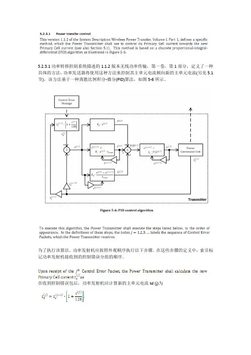
5.2.3.1功率转移控制系统描述的1.1.2版本无线功率传输,第一卷,第1部分,定义了一种具体的方法,功率发送器将使用这种方法来控制其主单元电流朝向新的主单元电流(另见5.1节),该方法基于一种离散比例积分-微分(PID)算法,如图5-6所示。
为了执行该算法,功率发射机应按照外观顺序执行以下步骤。
在这些步骤的定义中,索引标记功率发射机接收到的控制错误分组的顺序。
在收到控制错误包后,功率发射机应计算新的主单元电流td (j)为其中ta(j-1)表示实际的主单元电流(响应于先前的控制错误包)和c(j)表示控制错误包中包含的控制错误值。
注意,ta (0)表示功率传输阶段开始时的主单元电流。
如果控制误差值c(j)为非零,则功率发射器应在时间窗内调整其主工作电流t(active)。
为此,功率发送器应执行由下列步骤组成的循环。
索引i = 1,2,3,...i(max)标记此回路的迭代。
功率发射器应计算新的主单元电流与实际的一次单元电流之间的差作为误差。
ta(j,i-1)表示在循环迭代中确定的主单元电流。
注意,ta(j,0)表示回路开始时的实际主单元电流。
发射器须计算比例、积分和导数项(按任何顺序):这里Kp是比例增益,Ki是积分增益,Kd是导数增益,t(inner)是执行一次循环迭代所需的时间。
此外,积分项I(j,0)和error e(j,0) = 0。
功率发送器应限制积分项I(j,i),使其保持在量程范围内-M(i)......+M(i)必要时,功率发射器应用适当的边界值代替计算的积分项I(ji)。
功率发射器须计算比例、积分及微分项之和:在此计算中,功率发射器应限制总和PID(j,i),以使其保持在范围-M(PID)......+M(PID)内。
功率发射器应计算受控变量的新值其中Sv是依赖于受控变量的缩放因子。
此外,受控变量v(j,0) = v(j-1,i max),v(0,0)表示在功率发射阶段开始时受控变量的实际值。
qi2标准范文"Qi2标准"在英文中有两种常见的翻译方式:Qi2 Standard和Qi2 Criteria。
Qi2是一种无线充电技术标准,也是一项能够传输能量的国际无线充电标准。
本文将从背景、功能、应用和意义四个方面,以1200字以上对Qi2标准进行介绍。
背景:在移动互联网时代,用户对于设备的便携性和无线充电的需求越来越高。
为了满足这种需求,无线充电技术应运而生。
然而,由于市场上存在着多种不同的无线充电技术标准,无法实现充电器的通用性和互操作性。
鉴于此,Wireless Power Consortium(无线电力联盟)成立了Qi2工作组,旨在制定一项国际无线充电技术标准。
功能:Qi2标准是一种采用电磁感应原理的无线充电技术,通过无线电波在发射器和接收器之间传输能量。
Qi2标准规定了充电器和设备之间的物理接口标准,确保了充电设备的互操作性和通用性。
根据Qi2标准,设备包括两个主要组件:发射器(Transmitter)和接收器(Receiver)。
发射器负责发出电磁波,接收器则负责接收并转化电磁波为电能,供给设备充电。
Qi2标准还规定了不同设备之间的最大功率传输限制,确保了设备的安全性。
应用:意义:Qi2标准的制定和推广对于充电技术市场的发展具有重要意义。
首先,Qi2标准统一了无线充电的接口和传输标准,提高了充电设备之间的通用性和互操作性,为用户带来了更好的充电体验。
与此同时,Qi2标准还将不同制造商的产品纳入同一标准下,促进了充电技术的创新和发展,提升了整个行业的竞争力。
其次,Qi2标准的推广还有助于减少电子设备的碳排放。
无线充电技术的普及能够减少使用电线和充电器所带来的电子废料和资源浪费,进一步推动绿色环保意识的发展。
综上所述,Qi2标准作为一项国际无线充电技术标准,在移动互联网时代发挥着重要作用。
通过制定无线充电器和设备之间的物理接口标准,Qi2标准确保了充电设备的通用性和互操作性。

Qi无线充电国际标准
Qi是目前全球首个无线充电标准,可广泛用于手机、MP3、数码相机、笔记本电脑等设备中。
无线充电国际标准可以让我们抛弃拖着长线的充电器,在无线的状态下为手机充电。
Qi无线充电国际标准主要利用电磁技术,在发射器将电流转化为电磁,手机通过内置芯片接收器将电磁转化为电流为手机充电。
在目前出现的几种无线充电技术中,Qi的充电效率与有线充电方式非常接近,达到了70%以上,而Qi的充电站的待机耗电量则已经降低到微瓦水平。
2010年08月31日无线充电联盟宣布将Qi无线充电国际标准引入中国,该标准可在无线充电联盟网站下载。
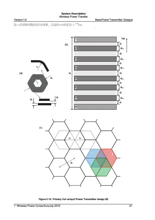
表3-9是初级线圈组相关的参数,完成的PCB厚度是1.3 mm.+10%-System DescriptionWireless Power Transfer Basic Power Transmitter Designs Version 1.0 3.3.2.1.2 3.3.2.1.33.3.2.23.3.2.3屏蔽罩界面/感应面电子细节描述功率发射器B2 使用的屏蔽罩和功率发射器B1使用的功率发射器使用的相同。
参考小节3.3.1.1.2从初级线圈组到基站界面/感应面的距离是 d Z =2 mm,(从初级线圈组顶面)。
同样参考小节3.3.1.1.3图3-11。
另外基站的界面/感应面至少超出初级线圈组的外边缘5mm.B2功率发射器设计的电路草图和功率发射器B1 的相同,参考小节3.3.1.2图3-12.功率发射器B2 用一个半桥逆变器驱动 初级线圈组。
另外功率发射器B2 用多路器选择有效区的位置。
多路器配置初级线圈组,像这样 1,2或者3套初级线圈被并联到驱动电路。
被连接在一起的初级线圈构成了一个初级子感应区。
还有另外一个限制 是多路器必须选择的每一个初级线圈要和其它每个选择的初级线圈叠加;参考例图 3-14(c)工作频率范围 f op =105--112kHz,每套在第2层 第7层(并联) 的初级线圈组和屏蔽罩的电感为 ---- 11.7uH , 在第3层和第六层(并联)为11.8 uH , 在第4层和第5层(并联)为12.3 uH 。
电容和电感在阻抗匹配电路中的(图3-12)分别为 C m1=256 nF , C m23=147 nF , L m =3.8 uH.电容 C_1和C_2在半桥逆变器为68uF.开关S是打开的当初级子感应区只有一个初级线圈组成时,否则开关就是关闭的。
(电容两端)通过电容的电压能达到36Vpk-pk。
功率发射器B2 用输入电压到半桥逆变器 从而控制功率大小的传输。
因为这个目的,输入电压的范围是0----20v,低输入电压结果就是低功率传输。
qi无线充电协议Qi无线充电协议是一种无线充电技术标准,由Wireless Power Consortium(WPC)制定并推广。
该协议的目标是为不同品牌和型号的移动设备提供统一的无线充电解决方案,使用户能够方便快速地进行无线充电。
首先,Qi无线充电协议采用了非接触式充电技术,通过电磁感应实现移动设备的充电。
用户只需将支持Qi无线充电的设备放置在充电器上,充电器会向设备发送电能,并通过感应线圈将电能转化为电流,从而实现设备的充电。
其次,Qi无线充电协议具有广泛的兼容性。
几乎所有支持Qi 无线充电的设备都可以通过通用的充电器进行充电,无需安装任何额外的适配器或进行特殊的设置。
这使得用户可以在不同品牌和型号的设备之间实现互相充电,极大地方便了用户的使用。
第三,Qi无线充电协议支持高效的充电。
与传统的有线充电相比,Qi无线充电协议采用了高频率的电磁感应技术,能够提供更快速、更高效的充电效果。
同时,该协议还支持智能充电管理,能够自动监测设备的电池状态并调整充电功率,以最佳方式为设备充电,提高充电效率。
此外,Qi无线充电协议还具有安全性和可靠性的优势。
该协议在充电过程中会进行温度监控和电流控制,以避免设备过热或过流,确保充电的安全性。
同时,该协议还支持互锁机制,防止充电器设备被非法复制或使用,保证充电过程的可靠性。
值得一提的是,Qi无线充电协议还在不断的演进和改进中。
目前已经发布了Qi v1.0、Qi v1.1、Qi v1.2等多个版本,每个版本都相对于前一个版本有一定的改进和提升。
例如,Qi v1.2版本增加了多设备充电和距离充电的支持,进一步提升了充电的便利性和灵活性。
综上所述,Qi无线充电协议是一种方便、快速、高效、安全和可靠的无线充电技术标准。
随着越来越多的移动设备支持该协议,用户将能够摆脱传统的有线充电方式,享受更加便捷的充电体验。
未来,Qi无线充电协议有望进一步改进和普及,为用户提供更好的充电解决方案。
QI无线充电标准V1.01概述1.1围系统描述无线电能传输第1卷包含以下文档:●第一部分:接口定义●第二部分:性能要求●第三部分:兼容性测试该文件定义了一个电能发射器和一个电能接收器之间的接口。
1.2主要特性●一种基于线圈之间的近场电磁感应原理,将电能从发射器传输到移动设备(接收器)的非接触式电能传输方法。
●通过一个适当的次级线圈(典型尺寸是大约40mm)来传输约5瓦特的电能。
●工作频率在110~205KHz之间。
●支持两种将移动设备放置于发射器表面的方法:✧辅助定位方法帮助用户适当地将移动设备放在通过表面上一个或几个固定的位置来传输电能的发射器的表面。
✧无需定位方法允许移动设备任意放在支持表面任何位置传输能量的发射器表面。
●一个简单的允许移动设备完全控制电能传送的通信协议。
●相当大的可集成在移动设备上的设计灵活性。
●极低的待机功耗(实现需要)。
1.3一致性与参考本文档中的所有规定都是强制性的,除非特别指明是推荐的、可选的或加强说明的。
为避免产生疑问,单词“应”表示指定部分为强制行为,也就是说,如果指定的部分没有所定义的行为,则这就违反了无线电能传输标准。
此外,单词“应该”表示指定部分为推荐行为,也就是说,如果指定的组件有正当理由偏离所定义的行为,则这不是违反了无线电能传输标准的。
最后,单词“可以”表示指定组件的可选行为,也就是说,是否具有所定义的行为(没有偏离)是取决于指定组件。
除本文件所提出的规外,产品的实现也应符合下面所列出的系统说明所提出的规。
此外,下列国际标准的相关部分也应遵守。
如果任何系统描述或以下所列出的国际标准存在多个修订版本,以最新版本为准。
[第2部] 无线电能传输系统描述,第I卷,第2部分,性能要求。
[第3 部] 无线电能传输系统描述,第I卷,第3部分,兼容性测试。
[PRMC] 电源接收器制造商代码,无线充电联盟。
[SI] 国际计量制。
1.4定义有效区域:当发射器向移动设备供电时,发射器和接收器各自表面的一部分有足够高的磁场通过的区域。
qi无线充电标准无线充电技术是近年来备受关注的一项新兴技术,它摆脱了传统充电方式的束缚,让人们可以更加便捷地为各种设备充电。
在无线充电技术中,Qi无线充电标准是目前应用最为广泛的一种标准,它由无线电力联盟(Wireless Power Consortium)制定,已经成为全球范围内的无线充电标准之一。
首先,Qi无线充电标准的核心原理是通过电磁感应实现能量传输。
在充电过程中,充电器产生一个交变磁场,而设备内置的接收线圈则可以利用这个磁场产生感应电流,从而实现能量传输和充电。
这种原理不仅可以让设备在不接触充电器的情况下进行充电,还可以为设备提供更加便捷的充电方式,也减少了充电接口的磨损和故障的可能性。
其次,Qi无线充电标准在充电效率和安全性方面也有着一定的保障。
在充电效率方面,Qi标准可以实现高达70%以上的能量传输效率,相比于传统有线充电方式,虽然还有一定的提升空间,但已经能够满足大部分用户的日常充电需求。
在安全性方面,Qi标准通过对传输功率、温度和设备识别等方面的严格控制,可以有效地避免过热、过载等安全问题,保障用户和设备的安全。
此外,Qi无线充电标准的普及也得益于其开放性和兼容性。
作为一项开放的标准,任何符合Qi标准的设备都可以使用任何符合Qi标准的充电器进行充电,这种兼容性使得用户可以更加便捷地使用充电设备,也为设备厂商提供了更多的市场机会。
同时,无线充电技术的发展也在不断推动Qi标准的升级和完善,未来将会有更多的设备和场景支持Qi标准,让无线充电成为更加普及和便捷的充电方式。
总的来说,Qi无线充电标准作为一种新兴的充电技术标准,具有着诸多优势和潜力。
它通过电磁感应实现能量传输,提高了充电的便捷性和舒适度;在充电效率和安全性方面也有着一定的保障;同时,其开放性和兼容性也为用户和设备厂商带来了更多的便利和机会。
随着无线充电技术的不断发展和普及,相信Qi无线充电标准将会在未来发挥更加重要的作用,成为各种设备充电的主流方式之一。
QI无线充电标准V1.01概述1.1范围系统描述无线电能传输第1卷包含以下文档:●第一部分:接口定义●第二部分:性能要求●第三部分:兼容性测试该文件定义了一个电能发射器和一个电能接收器之间的接口。
1.2主要特性●一种基于线圈之间的近场电磁感应原理,将电能从发射器传输到移动设备(接收器)的非接触式电能传输方法。
●通过一个适当的次级线圈(典型尺寸是大约40mm)来传输约5瓦特的电能。
●工作频率在110~205KHz之间。
●支持两种将移动设备放置于发射器表面的方法:✧辅助定位方法帮助用户适当地将移动设备放在通过表面上一个或几个固定的位置来传输电能的发射器的表面。
✧无需定位方法允许移动设备任意放在支持表面任何位置传输能量的发射器表面。
●一个简单的允许移动设备完全控制电能传送的通信协议。
●相当大的可集成在移动设备上的设计灵活性。
●极低的待机功耗(实现需要)。
1.3一致性与参考本文档中的所有规定都是强制性的,除非特别指明是推荐的、可选的或加强说明的。
为避免产生疑问,单词“应”表示指定部分为强制行为,也就是说,如果指定的部分没有所定义的行为,则这就违反了无线电能传输标准。
此外,单词“应该”表示指定部分为推荐行为,也就是说,如果指定的组件有正当理由偏离所定义的行为,则这不是违反了无线电能传输标准的。
最后,单词“可以”表示指定组件的可选行为,也就是说,是否具有所定义的行为(没有偏离)是取决于指定组件。
除本文件所提出的规范外,产品的实现也应符合下面所列出的系统说明所提出的规范。
此外,下列国际标准的相关部分也应遵守。
如果任何系统描述或以下所列出的国际标准存在多个修订版本,以最新版本为准。
[第2部] 无线电能传输系统描述,第I卷,第2部分,性能要求。
[第3 部] 无线电能传输系统描述,第I卷,第3部分,兼容性测试。
[PRMC] 电源接收器制造商代码,无线充电联盟。
[SI] 国际计量制。
1.4定义有效区域:当发射器向移动设备供电时,发射器和接收器各自表面的一部分有足够高的磁场通过的区域。
System Description Wireless Power TransferVolume I: Low Power Part 1: Interface DefinitionVersion 1.0July 2010Wireless Power TransferVersion 1.0System DescriptionWireless Power TransferVolume I: Low PowerPart 1: Interface DefinitionVersion 1.0July 2010Wireless Power TransferVersion 1.0 COPYRIGHTThis System Description Wireless Power Transfer is published by the Wireless Power Consortium, and has been prepared by the Wireless Power Consortium in close co-operation with ConvenientPower Ltd., Fulton Innovation LLC, National Semiconductor Corporation, Nokia Corporation, Olympus Imaging Corporation, Research In Motion, Limited, Royal Philips Electronics, Sanyo Electric Co. Ltd., Shenzhen Sang Fei Consumer Communications Co. Ltd., and Texas Instruments Inc.. All rights are reserved. Reproduction in whole or in part is prohibited without express and prior written permission of the Wireless Power Consortium.DISCLAIMERThe information contained herein is believed to be accurate as of the date of publication. However, neither the Wireless Power Consortium, nor ConvenientPower Ltd., nor Fulton Innovation LLC, nor National Semiconductor Corporation, nor Nokia Corporation, nor Olympus Imaging Corporation, nor Research In Motion Limited, nor Royal Philips Electronics, nor Sanyo Electric Co. Ltd., nor Shenzhen Sang Fei Consumer Communications Co. Ltd., nor Texas Instruments Inc. will be liable for any damages, including indirect or consequential, from use of this System Description Wireless Power Transfer or reliance on the accuracy of this document.CLASSIFICATIONThe information contained in this document is marked as confidential.NOTICEFor any further explanation of the contents of this document, or in case of any perceived inconsistency or ambiguity of interpretation, or for any information regarding the associated patent license program, please contact: info@.Version 1.0 Table of ContentsTable of Contents1General (1)1.1Scope (1)1.2Main features (1)1.3Conformance and references (1)1.4Definitions (2)1.5Acronyms (3)1.6Symbols (3)1.7Conventions (4)1.7.1Cross references (4)1.7.2Informative text (4)1.7.3Terms in capitals (4)1.7.4Notation of numbers (4)1.7.5Units of physical quantities (4)1.7.6Bit ordering in a byte (4)1.7.7Byte numbering (5)1.7.8Multiple-bit Fields (5)1.8Operators (5)1.8.1Exclusive-OR (5)1.8.2Concatenation (5)2System Overview (Informative) (7)3Basic Power Transmitter Designs (11)3.1Introduction (11)3.2Power Transmitter designs that are based on a single Primary Coil (11)3.2.1Power Transmitter design A1 (11)3.2.2Power Transmitter design A2 (16)3.3Power Transmitter designs that are based on an array of Primary Coils (20)3.3.1Power Transmitter design B1 (20)3.3.2Power Transmitter design B2 (26)4Power Receiver Design Requirements (29)4.1Introduction (29)4.2Power Receiver design requirements (30)4.2.1Mechanical requirements (30)4.2.2Electrical requirements (31)5System Control (35)5.1Introduction (35)5.2Power Transmitter perspective (38)5.2.1Ping phase (38)5.2.2Identification & configuration phase (39)5.2.3Power transfer phase (42)5.3Power Receiver perspective (46)5.3.1Selection phase (46)5.3.2Ping phase (47)Table of Contents Version 1.05.3.3Identification & configuration phase (47)5.3.4Power transfer phase (48)6Communications Interface (51)6.1Introduction (51)6.2Physical and data link layers (51)6.2.1Modulation scheme (51)6.2.2Bit encoding scheme (52)6.2.3Byte encoding scheme (52)6.2.4Packet structure (52)6.3Logical layer (55)6.3.1Signal Strength Packet (0x01) (55)6.3.2End Power Transfer Packet (0x02) (56)6.3.3Control Error Packet (0x03) (57)6.3.4Rectified Power Packet (0x04) (57)6.3.5Charge Status Packet (0x05) (57)6.3.6Power Control Hold-off Packet (0x06) (57)6.3.7Configuration Packet (0x51) (58)6.3.8Identification Packet (0x71) (58)6.3.9Extended Identification Packet (0x81) (60)Annex A Example Power Receiver Designs (Informative) (61)A.1Power Receiver example 1 (61)A.1.1Mechanical details (61)A.1.2Electrical details (62)A.2Power Receiver example 2 (64)A.2.1Mechanical details (64)A.2.2Electrical details (65)Annex B Object Detection (Informative) (67)B.1Resonance shift (67)B.2Capacitance change (68)Annex C Power Receiver Localization (Informative) (69)C.1Guided Positioning (69)C.2Primary Coil array based Free Positioning (69)C.2.1 A single Power Receiver covering multiple Primary Cells (69)C.2.2Two Power Receivers covering two adjacent Primary Cells (70)C.2.3Two Power Receivers covering a single Primary Cell (70)C.3Moving Primary Coil based Free Positioning (71)Annex D Metal Object Detection (Informative) (73)Version 1.0 Table of Contents List of FiguresFigure 1-1: Bit positions in a byte (5)Figure 1-2: Example of multiple-bit field (5)Figure 2-1: Basic system overview (8)Figure 3-1: Functional block diagram of Power Transmitter design A1 (11)Figure 3-2: Primary Coil of Power Transmitter design A1 (12)Figure 3-3: Primary Coil assembly of Power Transmitter design A1 (13)Figure 3-4: Electrical diagram (outline) of Power Transmitter design A1 (14)Figure 3-5: Functional block diagram of Power Transmitter design A2 (16)Figure 3-6: Primary Coil of Power Transmitter design A2 (17)Figure 3-7: Primary Coil assembly of Power Transmitter design A2 (18)Figure 3-8: Electrical diagram (outline) of Power Transmitter design A2 (19)Figure 3-9: Functional block diagram of Power Transmitter design B1 (20)Figure 3-10: Primary Coil array of Power Transmitter design B1 (21)Figure 3-11: Primary Coil array assembly of Power Transmitter design B1 (22)Figure 3-12: Electrical diagram (outline) of Power Transmitter design B1 (23)Figure 3-13: Multiple type B1 Power Transmitters sharing a multiplexer and Primary Coil array (25)Figure 3-14: Primary Coil array of Power Transmitter design B2 (27)Figure 4-1: Example functional block diagram of a Power Receiver (29)Figure 4-2: Secondary Coil assembly (30)Figure 4-3: Dual resonant circuit of a Power Receiver (31)Figure 4-4: Characterization of resonant frequencies (32)Figure 5-1: Power transfer phases (35)Figure 5-2: Power transfer control loop (37)Figure 5-3: Power Transmitter timing in the ping phase (39)Figure 5-4: Power Transmitter timing in the identification & configuration phase (41)Figure 5-5: Power Transmitter timing in the power transfer phase (43)Figure 5-6: PID control algorithm (44)Figure 5-7: Power Receiver timing in the selection phase (47)Figure 5-8: Power Receiver timing in the ping phase (47)Figure 5-9: Power Receiver timing in the identification & configuration phase (48)Figure 5-10: Power Receiver timing in the power transfer phase (49)Figure 6-1: Amplitude modulation of the Power Signal (51)Figure 6-2: Example of the differential bi-phase encoding (52)Figure 6-3: Example of the asynchronous serial format (52)Figure 6-4: Packet format (53)Figure A-1: Secondary Coil of Power Receiver example 1 (61)Figure A-2: Secondary Coil and Shielding assembly of Power Receiver example 1 (62)Figure A-3: Electrical details of Power Receiver example 1 (62)Figure A-4: Li-ion battery charging profile (63)Figure A-5: Secondary Coil of Power Receiver example 2 (64)Figure A-6: Secondary Coil and Shielding assembly of Power Receiver example 2 (65)Figure A-7: Electrical details of Power Receiver example 2 (66)Figure B-1: Analog ping based on a resonance shift (67)Figure C-1: Single Power Receiver covering multiple Primary Cells (70)Figure C-2: Two Power Receivers covering two adjacent Primary Cells (70)Figure C-3: Two Power Receivers covering a single Primary Cell (71)Figure C-4: Detection Coil (72)Table of Contents Version 1.0 List of TablesTable 3-1: Primary Coil parameters of Power Transmitter design A1 (12)Table 3-2: PID parameters for Operating Frequency control (14)Table 3-3: Operating Frequency dependent scaling factor (14)Table 3-4: PID parameters for duty cycle control (15)Table 3-5: Primary Coil parameters of Power Transmitter design A2 (17)Table 3-6: PID parameters for voltage control (19)Table 3-7: Primary Coil array parameters of Power Transmitter design B1 (22)Table 3-8: PID parameters for voltage control (24)Table 3-9: Primary Coil array parameters of Power Transmitter design B2 (26)Table 5-1: Power Transmitter timing in the ping phase (38)Table 5-2: Power Transmitter timing in the identification & configuration phase (41)Table 5-3: Power control hold-off time (41)Table 5-4: Power Transmitter timing in the power transfer phase (44)Table 5-5: Power Receiver timing in any phase (46)Table 5-6: Power Receiver timing in the selection phase (47)Table 5-7: Power Receiver timing in the identification & configuration phase (48)Table 5-8: Power Receiver timing in the power transfer phase (49)Table 6-1: Amplitude modulation of the Power Signal (52)Table 6-2: Message size (53)Table 6-3: Packet types (54)Table 6-4: Signal Strength (55)Table 6-5: End Power Transfer (56)Table 6-6: End Power Transfer values (56)Table 6-7: Control Error (57)Table 6-8: Rectified Power (57)Table 6-9: Charge Status (57)Table 6-10: Power control hold-off (58)Table 6-11: Configuration (58)Table 6-12: Identification (59)Table 6-13: Extended Identification (60)Table A-1: Secondary Coil parameters of Power Receiver example 1 (61)Table A-2: Parameters of the Secondary Coil of Power Receiver example 2 (64)Table B-1: Analog ping based on a resonance shift (67)Version 1.0 General1General1.1ScopeVolume I of the System Description Wireless Power Transfer consists of the following documents: ∙Part 1, Interface Definition.∙Part 2, Performance Requirements.∙Part 3, Compliance Testing.This document defines the interface between a Power Transmitter and a Power Receiver.1.2Main features∙ A method of contactless power transfer from a Base Station to a Mobile Device, which is based on near field magnetic induction between coils.∙Transfer of around 5 W of power, using an appropriate Secondary Coil (having a typical outer dimension of around 40 mm).∙Operation at frequencies in the 110…205 kHz range.∙Support for two methods of placing the Mobile Device on the surface of the Base Station: o Guided Positioning helps a user to properly place the Mobile Device on the surface of a Base Station that provides power through a single or a few fixed locations of that surface.o Free Positioning enables arbitrary placement of the Mobile Device on the surface of a Base Station that can provide power through any location of that surface.∙ A simple communications protocol enabling the Mobile Device to take full control of the power transfer.∙Considerable design flexibility for integration of the system into a Mobile Device.∙Very low stand-by power achievable (implementation dependent).1.3Conformance and referencesAll specifications in this document are mandatory, unless specifically indicated as recommended or optional or informative. To avoid any doubt, the word “shall”indicates a mandatory behavior of the specified component, i.e. it is a violation of this System Description Wireless Power Transfer if the specified component does not exhibit the behavior as defined. In addition, the word “should” indicates a recommended behavior of the specified component, i.e. it is not a violation of this System Description Wireless Power Transfer if the specified component has valid reasons to deviate from the defined behavior. And finally, the word “may” indicates an optional behavior of the specified component, i.e. it is up to the specified component whether to exhibit the defined behavior (without deviating there from) or not.In addition to the specifications provided in this document, product implementations shall also conform to the specifications provided in the System Descriptions listed below. Moreover, the relevant parts of the International Standards listed below shall apply as well. If multiple revisions exist of any System Description or International Standard listed below, the applicable revision is the one that was most recently published at the release date of this document.[Part 2] System Description Wireless Power Transfer, Volume I, Part 2, Performance Requirements.[Part 3] System Description Wireless Power Transfer, Volume I, Part 3, Compliance Testing.[PRMC] Power Receiver Manufacturer Codes, Wireless Power Consortium.General Version 1.0 [SI] The International System of Units (SI), Bureau International des Poids etMesures.1.4DefinitionsActive Area The part of the Interface Surface of a Base Station respectively Mobile Devicethrough which a sufficiently high magnetic flux penetrates when the BaseStation is providing power to the Mobile Device.Base Station A device that is able to provide near field inductive power as specified in thisSystem Description Wireless Power Transfer. A Base Station carries a logo tovisually indicate to a user that the Base Station complies with this SystemDescription Wireless Power Transfer.Communications and Control UnitThe functional part of a Power Transmitter respectively Power Receiver thatcontrols the power transfer. (Informative) Implementation-wise, theCommunications and Control Unit may be distributed over multiple subsystems ofthe Base Station respectively Mobile Device.Control Point The combination of voltage and current provided at the output of the PowerReceiver, and other parameters that are specific to a particular Power Receiverimplementation.Detection Unit The functional part of a Power Transmitter that detects the presence of a PowerReceiver on the Interface Surface.Digital Ping The application of a Power Signal in order to detect and identify a PowerReceiver.Free Positioning A method of positioning a Mobile Device on the Interface Surface of a BaseStation that does not require the user to align the Active Area of the MobileDevice to the Active Area of the Base Station.Guided Positioning A method of positioning a Mobile Device on the Interface Surface of a BaseStation that provides the user with feedback to properly align the Active Area ofthe Mobile Device to the Active Area of the Base Station.Interface Surface A flat part of the surface of a Base Station respectively Mobile Device that isclosest to the Primary Coil(s) respectively Secondary Coil.Mobile Device A device that is able to consume near field inductive power as specified in thisSystem Description Wireless Power Transfer. A Mobile Device carries a logo tovisually indicate to a user that the Mobile Device complies with this SystemDescription Wireless Power Transfer.Operating Frequency The oscillation frequency of the Power Signal.Operating Point The combination of the frequency, duty cycle and amplitude of the voltage thatis applied to the Primary Cell.Packet A data structure that the Power Receiver uses to communicate a message to thePower Transmitter. A Packet consists of a preamble, a header byte, a message,and a checksum. A Packet is named after the kind of message that it contains. Power Conversion Unit The functional part of a Power Transmitter that converts electrical energy to aPower Signal.Power Pick-up Unit The functional part of a Power Receiver that converts a Power Signal toelectrical energy.Power Receiver The subsystem of a Mobile Device that acquires near field inductive power andcontrols its availability at its output, as defined in this System DescriptionWireless Power Transfer. For this purpose, the Power Receiver communicatesits power requirements to the Power Transmitter.Version 1.0 General Power Signal The oscillating magnetic flux that is enclosed by a Primary Cell and possibly a Secondary Coil.Power Transfer Contract A set of boundary conditions on the parameters that characterize the power transfer from a Power Transmitter to a Power Receiver. Violation of any ofthese boundary conditions causes the power transfer to abort.Power Transmitter The subsystem of a Base Station that generates near field inductive power and controls its transfer to a Power Receiver, as defined in this System DescriptionWireless Power Transfer.Primary Cell A single Primary Coil or a combination of Primary Coils that are used to providea sufficiently high magnetic flux through the Active Area.Primary Coil A component of a Power Transmitter that converts electric current to magnetic flux.Secondary Coil The component of a Power Receiver that converts magnetic flux to electromotive force.Shielding A component in the Power Transmitter respectively Power Receiver that restricts magnetic fields to the appropriate parts of the Base Stationrespectively Mobile Device.1.5AcronymsAC Alternating CurrentAWG American Wire GaugeDC Direct Currentlsb least significant bitmsb most significant bitN.A. Not ApplicablePID Proportional Integral DifferentialRMS Root Mean SquareUART Universal Asynchronous Receiver Transmitter1.6SymbolsC d Capacitance parallel to the Secondary Coil [nF]C m Capacitance in the impedance matching network [nF]Capacitance in series with the Primary Coil [nF]C S Capacitance in series with the Secondary Coil [nF]Distance between a coil and its Shielding [mm]Distance between a coil and the Interface Surface [mm]Communications bit rate [kHz]Resonant detection frequency [kHz]Operating Frequency [kHz]Secondary resonance frequency [kHz]Primary Coil current modulation depth [mA]Power Receiver output current [mA]Primary Coil current [mA]L m Inductance in the impedance matching network [μH]General Version 1.0Primary Coil self inductance [μH]Secondary Coil self inductance (Mobile Device away from Base Station) [μH]Secondary Coil self inductance (Mobile Device on top of Base Station) [μH]Total amount of power received through the Interface Surface [W]Total amount of power transmitted through the Interface Surface [W]Power Control Hold-off Time [ms]Communications clock period [μs]Maximum transition time of the communications [μs]Rectified voltage [V]Power Receiver output voltage [V]1.7ConventionsThis Section 1.7 defines the notations and conventions used in this System Description Wireless Power Transfer.1.7.1Cross referencesUnless indicated otherwise, cross references to Sections in either this document or documents listed in Section 1.3, refer to the referenced Section as well as the sub Sections contained therein.1.7.2Informative textWith the exception of Sections that are marked as informative, all informative text is set in italics.1.7.3Terms in capitalsAll terms that start with a capital are defined in Section 1.4. As an exception to this rule, Packet names and fields are defined in Section 6.3.1.7.4Notation of numbersReal numbers are represented using the digits 0 to 9, a decimal point, and optionally an exponential part. In addition, a positive and/or negative tolerance may follow a real number. Real numbers that do not include an explicit tolerance, have a tolerance of half the least significant digit that is specified. (Informative) For example, a specified value of comprises the range from 1.21 through 1.24; a specified value of comprises the range from 1.23 through 1.24; a specified value of comprises the range from 1.21 through 1.23; a specified value of 1.23 comprises the range from 1.225 through 1.234999…; and a specified value of comprises the range from 1.107 through 1.353. Integer numbers in decimal notation are represented using the digits 0 to 9.Integer numbers in hexadecimal notation are represented using the hexadecimal digits 0 to 9 and A to F, and are preceded by “0x” (unless explicitly indicated otherwise).Single bit values are represented using the words ZERO and ONE.Integer numbers in binary notation and bit patterns are represented using sequences of the digits 0 and 1that are enclosed in single quotes (‘’). In a sequence of n bits, the most significant bit (msb) is bit b n–1 and the least significant bit (lsb) is bit b0; the most significant bit is shown on the left-hand side.1.7.5Units of physical quantitiesPhysical quantities are expressed in units of the International System of Units [SI].1.7.6Bit ordering in a byteThe graphical representation of a byte is such that the msb is on the left, and the lsb is on the right. Figure 1-1 defines the bit positions in a byte.Version 1.0 General msb lsbFigure 1-1: Bit positions in a byte1.7.7Byte numberingThe bytes in a sequence of n bytes are referred to as B0, B1, …, B n–1. Byte B0 corresponds to the first byte in the sequence; byte B n–1 corresponds to the last byte in the sequence. The graphical representation of a byte sequence is such that B0 is at the upper left-hand side, and byte B n–1 is at the lower right-hand side. 1.7.8Multiple-bit FieldsUnless indicated otherwise, a multiple bit field in a data structure represents an unsigned integer value. In a multiple-bit field that spans multiple bytes, the msb of the multiple-bit field is located in the byte with the lowest address, and the lsb of the multiple-bit field is located in the byte with the highest address. (Informative) Figure 1-2 provides an example of a 6-bit field that spans two bytes.B0B1Figure 1-2: Example of multiple-bit field1.8OperatorsThis Section 1.8 defines the operators used in this System Description Wireless Power Transfer, which are less commonly used. The commonly used operators have their usual meaning.1.8.1Exclusive-ORThe symbol ‘ ’ represents the exclusive-OR operation.1.8.2ConcatenationThe symbol ‘||’ represents concatenation of two bit strings. In the resulting concatenated bit string, the msb of the right-hand side operand directly follows the lsb of the left-hand side operand.General Version 1.0This page is intentionally left blank.Version 1.0 System Overview (Informative)2System Overview (Informative)Operation of devices that comply with this System Description Wireless Power Transfer relies on magnetic induction between planar coils. Two kinds of devices are distinguished, namely devices that provide wireless power—referred to as Base Stations—and devices that consume wireless power—referred to as Mobile Devices. Power transfer always takes place from a Base Station to a Mobile Device. For this purpose, a Base Station contains a subsystem—referred to as a Power Transmitter—that comprises a Primary Coil,1 and a Mobile Device contains a subsystem—referred to as a Power Receiver—comprises a Secondary Coil. In fact, the Primary Coil and Secondary Coil form the two halves of a coreless resonant transformer. Appropriate Shielding at the bottom face of the Primary Coil and the top face of the Secondary Coil, as well as the close spacing of the two coils, ensures that power transfer occurs with an acceptable efficiency. In addition, this Shielding minimizes the exposure of users to the magnetic field. Typically, a Base Station has a flat surface—referred to as the Interface Surface—on top of which a user can place one or more Mobile Devices. This ensures that the vertical spacing between Primary Coil and Secondary Coil is sufficiently small. In addition, there are two concepts for horizontal alignment of the Primary Coil and Secondary Coil. In the first concept—referred to as Guided Positioning—the user must actively align the Secondary Coil to the Primary Coil, by placing the Mobile Device on the appropriate location of the Interface Surface. For this purpose, the Mobile Device provides an alignment aid that is appropriate to its size, shape and function. The second concept—referred to as Free Positioning—does not require the active participation in alignment of the Primary Coil and Secondary Coil. One implementation of Free Positioning makes use of an array of Primary Coils to generate a magnetic field at the location of the Secondary Coil only. Another implementation of Free Positioning uses mechanical means to move a single Primary Coil underneath the Secondary Coil.Figure 2-1 illustrates the basic system configuration. As shown, a Power Transmitter comprises two main functional units, namely a Power Conversion Unit and a Communications and Control Unit. The diagram explicitly shows the Primary Coil (array) as the magnetic field generating element of the Power Conversion Unit. The Control and Communications Unit regulates the transferred power to the level that the Power Receiver requests. Also shown in the diagram is that a Base Station may contain multiple Transmitters in order to serve multiple Mobile Devices simultaneously (a Power Transmitter can serve a single Power Receiver at a time only). Finally, the system unit shown in the diagram comprises all other functionality of the Base Station, such as input power provisioning, control of multiple Power Transmitters, and user interfacing.A Power Receiver comprises a Power Pick-up Unit and a Communications and Control Unit. Similar to the Power Conversion Unit of the Transmitter, Figure 2-1 explicitly shows the Secondary Coil as the magnetic field capturing element of the Power Pick-up Unit. A Power Pick-up Unit typically contains a single Secondary Coil only. Moreover, a Mobile Device typically contains a single Power Receiver. The Communications and Control Unit regulates the transferred power to the level that is appropriate for the subsystems connected to the output of the Power Receiver. These subsystems represent the main functionality of the Mobile Device. An important example subsystem is a battery that requires charging. The remainder of this document is structured as follows. Section 3 defines the basic Power Transmitter designs, which come in two basic varieties. The first type of design—type A—is based on a single Primary Coil (either fixed position or moveable). The second type of design—type B—is based on an array of Primary Coils. Note that this version 1.0 of the System Description Wireless Power Transfer, Volume I, Part 1, offers only limited design freedom with respect to actual Power Transmitter implementations. The reason is that Mobile Devices exhibit a much greater variety of design requirements with respect to the Power Receiver than a Base Station does to Power Transmitters—for example, a smart phone has design requirements that differ substantially from those of a wireless headset. Constraining the Power Transmitter therefore enables interoperability with the largest number of mobile devices.1Note that the Primary Coil may be a “virtual coil,” in the sense that an appropriate array of planar coils can generate a magnetic field that is similar to the field that a single coil generates.System Overview (Informative) Version 1.0Figure 2-1: Basic system overviewSection 4 defines the Power Receiver design requirements. In view of the wide variety of Mobile Devices, this set of requirements has been kept to a minimum. In addition to the design requirements, Section 4 is complemented with two example designs in Annex A.Section 5 defines the system control aspects of the power transfer. The interaction between a Power Transmitter and a Power Receiver comprises four phases, namely selection, ping, identification & configuration, and power transfer. In the selection phase, the Power Transmitter attempts to discover and locate objects that are placed on the Interface Surface. In addition, the Power Transmitter attempts to discriminate between Power Receivers and foreign objects and to select a Power Receiver (or object) for power transfer. For this purpose, the Power Transmitter may select an object at random and proceed to the ping phase (and subsequently to the identification & configuration phase) to collect necessary information. Note that if the Power Transmitter does not initiate power transfer to a selected Power Receiver, it should enter a low power stand-by mode of operation.2In the ping phase, the Power Transmitter attempts to discover if an object contains a Power Receiver. In the identification & configuration phase, the Power Transmitter prepares for power transfer to the Power Receiver. For this purpose, the Power Transmitter retrieves relevant information from the Power Receiver. The Power Transmitter combines this information with information that it stores internally to construct a so-called Power Transfer Contract, which comprises various limits on the power transfer. In the power transfer2A definition of such a stand-by mode is outside the scope of this version 1.0 System Description Wireless Power Transfer, Volume I, Part 1. However, [Part 2] provides requirements on the maximum power use of a Power Transmitter when it is not actively providing power to a Power Receiver.。
QI标准1概述1.1范围系统描述无线电能传输第1卷包含以下文档:●第一部分:接口定义●第二部分:性能要求●第三部分:兼容性测试该文件定义了一个电能发射器和一个电能接收器之间的接口。
1.2主要特性●一种基于线圈之间的近场电磁感应原理,将电能从发射器传输到移动设备(接收器)的非接触式电能传输方法。
●通过一个适当的次级线圈(典型尺寸是大约40mm)来传输约5瓦特的电能。
●工作频率在110~205KHz之间。
●支持两种将移动设备放置于发射器表面的方法:✧辅助定位方法帮助用户适当地将移动设备放在通过表面上一个或几个固定的位置来传输电能的发射器的表面。
✧无需定位方法允许移动设备任意放在支持表面任何位置传输能量的发射器表面。
●一个简单的允许移动设备完全控制电能传送的通信协议。
●相当大的可集成在移动设备上的设计灵活性。
●极低的待机功耗(实现需要)。
1.3一致性与参考本文档中的所有规定都是强制性的,除非特别指明是推荐的、可选的或加强说明的。
为避免产生疑问,单词“应”表示指定部分为强制行为,也就是说,如果指定的部分没有所定义的行为,则这就违反了无线电能传输标准。
此外,单词“应该”表示指定部分为推荐行为,也就是说,如果指定的组件有正当理由偏离所定义的行为,则这不是违反了无线电能传输标准的。
最后,单词“可以”表示指定组件的可选行为,也就是说,是否具有所定义的行为(没有偏离)是取决于指定组件。
除本文件所提出的规范外,产品的实现也应符合下面所列出的系统说明所提出的规范。
此外,下列国际标准的相关部分也应遵守。
如果任何系统描述或以下所列出的国际标准存在多个修订版本,以最新版本为准。
[第2部] 无线电能传输系统描述,第I卷,第2部分,性能要求。
[第3 部] 无线电能传输系统描述,第I卷,第3部分,兼容性测试。
[PRMC] 电源接收器制造商代码,无线充电联盟。
[SI] 国际计量制。
1.4定义有效区域:当发射器向移动设备供电时,发射器和接收器各自表面的一部分有足够高的磁场通过的区域。
系统的描述,无线通信电源转换低功率第一部分:接口定义版本1.0,2010年7月版权该系统描述无线功率传输是出版的力量,无线通信联合体采用无线力量联盟与ConvenientPower有限公司密切合作,富尔顿创新公司、国家半导体公司,诺基亚公司,奥林匹斯成像公司、研究、限制、飞利浦、三洋电子公司。
深圳桑菲消费通信有限公司。
菲德州仪器有限公司,保留所有能量。
复制在全部或部分地是被禁止的明示和优先的书面允许的无线能力联盟。
免责声明本网站内所包含的信息是正确之日出版。
然而,无线的力量,也ConvenientPower协会有限公司,富尔顿创新公司和国家诺基亚公司半导体公司、企业、科研、奥林匹斯成像议案有限公司、飞利浦、三洋电子公司。
深圳桑菲消费通信有限公司。
德州仪器有限公司,也将承担任何损失,包括间接的或间接的,从使用这个系统描述无线功率传输或依据。
本文件的准确性。
分类在这个文件中所包含的信息是机密。
注意为进一步解释,这份文件的内容,或在任何可察觉不一致或模棱两可的解释,或为任何资讯相关的专利许可程序,请联系:********************************。
1 综述1.1范围,我的系统体积的无线功率传输由描述下列文件:第一部分:接口定义。
第二部分:性能要求。
第三部份:测试的依从。
本文档定义了的交互界面和供电功率发射机接收器。
1.2主要特征无触点电力传输的方法,从一个基站移动设备,它是基于近场磁感应线圈之间。
转移的功率,大约5 W采用适当的二次卷(典型的外部大约40毫米)的尺寸。
操作频率范围:110-205 HZ之间。
支持两种方法在移动设备上放置在基站的表面。
帮助用户指引正确位置的移动设备在表面形成一层。
通过基站,提供一个或几个固定位置的表面。
任意位置可以免费定位的移动设备上表面形成一层可提供电力基站位置,通过任何表面。
一个简单的通信协议使移动设备能够充分的控制能力转让。
可观的设计系统的灵活性为整合成一个移动的装置。
非常低的备用电源(执行),可依赖安装。
1.3一致性和参考本文档中所有的规定,除非特别指出,以及其他推荐或随意或信息。
为了避免任何疑惑,“应当”表示一个强制性的行为的指定的成分,如下。
它是一种违反这一系统的无线通信电源转换描述指定的成分不具有行为所定义的。
此外,“应该”表示推荐的行为的特定组件,如下。
它不是一种违反这一系统的描述如果指定的无线功率传输组件都有理由偏离的定义行为。
最后,这个词“可能”表示一个可选的行为的特定组件,如下。
它是到指定的成分是否具有明确的行为(从)或无偏差不是。
此外,在这个文件中提供的规格,还应当符合产品的实现在系统提供的规格说明如下。
而且,相关的部分下面列出适用的国际标准。
如果多个修改任何系统的存在描述或国际标准,适用于下面列出的是那个被修改在最近出版的发布日期的单据。
[2]部分描述无线功率传输系统,,第二部分,性能要求。
[3]系统部分描述无线功率传输、体积我,第三部分,遵守测试。
[PRMC]电力接收器制造商代码,无线力量联盟。
(SI)国际单位制(SI)、国际des Poids等措施。
1.4定义,活跃的部分的一个基站接口表面分别的移动设备通过一个足够高的磁通穿透当电台提供电力的移动设备。
基站一个装置,能提供近场电感功率按照本无线通信电源转换系统描述。
一个基站进行标识增加一个用户,符合本系统基站描述无线功率传输。
通讯和控制单元这个功能的一部分,分别接收功率发射机电源控制电源转换。
(信息)。
Implementation-wise,通讯和控制装置可能分布在多个子系统分别在基站移动设备。
这个组合的控制电压及电流之规定的输出功率接收机、及其他参数来指定一个特定的权力接收机实施。
探测单元的功能的一部分,一个功率发射机的权力在界面的表面。
数字平的申请,以便检测信号和识别能力接收机。
免费的定位方法的定位在移动设备的接口表面形成一层的基地电台不需要用户对正活跃的地区移动装置的基站活跃的地区。
引导定位方法的定位在移动设备的接口表面形成一层的基地站,为使用者提供反馈正确排列的活跃的地区手机活动区域的基站。
接口表面平坦的表面形成一层基站,分别为移动设备最近的初级线圈(s)次生线圈。
移动设备的一种设备,能消耗近场电感功率按照本无线通信电源转换系统描述。
一个移动装置进行标识增加一个用户的移动设备符合该系统描述无线功率传输。
操作频率振荡频率的信号。
操作频率,相结合的责任周期和幅值的电压适用于主要的细胞。
分组数据结构,方沟通的讯息功率发射机。
一个包包括序言,一个头球字节,一个消息,和一个校验。
一个包是命名,它包含的信息。
电源转换装置的功能的一部分,转换成电能的功率发射机力量的信号。
电力拾音器的功能的单位,将权力权力接收信号电能。
电力系统接收移动设备添置的近场感应力量和在输出控制算法的有效性,对该系统的描述无线通信电源转换。
为了这个目的,电力接收器沟通它的电力需求的功率发射机。
磁信号振荡,由一个基本单元,可能是一个第二组线圈。
权力转让合同一套边界条件对参数显示出力量从一个功率发射机电源接收机。
违反这些边界条件,使电力传输流产。
功率发射机系统基站产生了近场感应力量和控制它的权力转移,在接收系统的描述无线通信电源转换。
个单一的初级线圈小学细胞或组合的初级线圈用来提供2��个足够高的磁通通过活跃的地区。
初级线圈的功率发射机,转换成电流磁助焊剂。
第二组线圈的功率接收机的组件,转换成磁通到电动势。
屏蔽在组件功率发射机电源接收器,分别限制磁场,适当的部分基站各自的移动设备。
150首字母缩写AC交流电流AWG美国线测量直流直流lsb最低位结束msb最重要的一点美商并不适用PID比例积分-微分有效值的均方根通用异步接收器发射机。
UART16符号电容并联到二次Cd卷(nF)厘米的阻抗匹配网络电容(nF)电容串联在初级线圈(nF)CS电容串联在第二圈(nF)线圈之间的距离,其屏蔽[mm]线圈之间的距离的接口和表面[mm]通讯比特率[千赫]共振频率[千赫的检测[j].操作频率[千赫]二次谐振频率[千赫]初级线圈电流调制深度(马)电力接收器输出电流(马)初级线圈电流(马)中英电感的阻抗匹配网络[μH]初级线圈自感μH][m].北京:第二组线圈自感(手机)[m].北京:离基站μH]第二组线圈自感(移动设备上μH基站)[]通过对电力收到总额的接口表面(W)通过对电力传输总额的接口表面(W)功率控制Hold-off时间(ms)通讯的时钟周期μs][m].北京:最大的过渡时期的通讯[μs]整流电压[V]电力接收器输出电压[V]17公约这部分定义符号和惯例1.7%应用于该系统的描述无线能力转让。
1.7.1交叉引用除非另有、交叉引用表示在这个文件或部分所列文件13,指节段以及引用其中所含的子章节。
1.7.2翔实的文本除了部分被标记为信息,所有信息文本是用斜体印出的词。
1.7.3条款大写所有条款与资本的开始部分定义1.4。
作为例外,包的名字字段定义第6.3条。
1.7.4符号的编号真正的数字是代表了使用数字0 - 9、小数点、任意一个指数的一部分。
此外,一个积极的和/或负面的宽容可以遵循的实数。
真正的数字,却不是这样的,有一个明确的宽容,有一颗宽容的一半,是最显著的数字。
(信息),例如,一个指定的值包括从1.21通过124指定值的范围包括1.23 ~ 124;通过一个指定的值包括从1.21通过指定的值;1.23 1.23包括范围从1.225通过1.234999…一个指定的值,包括从1.107 1.353通过。
整数表示十进制表示法中使用数字0 - 9。
整数表示在十六进制使用十六进制数字0到9和一个外,“0x之前,除非明确指出(否则)。
单一位的值是0,表示一个的话。
用二进制记数法表示整数表示位模式,利用数字0和序列随信寄上1that 单引号(”)。
在一连串的n位,最重要的一点是一点bn-1受雇于和这个最低位(lsb)是位b0;最重要的一点是显示在左手边。
1.7.5单位的物理量对单位的物理量的国际单位制(SI)。
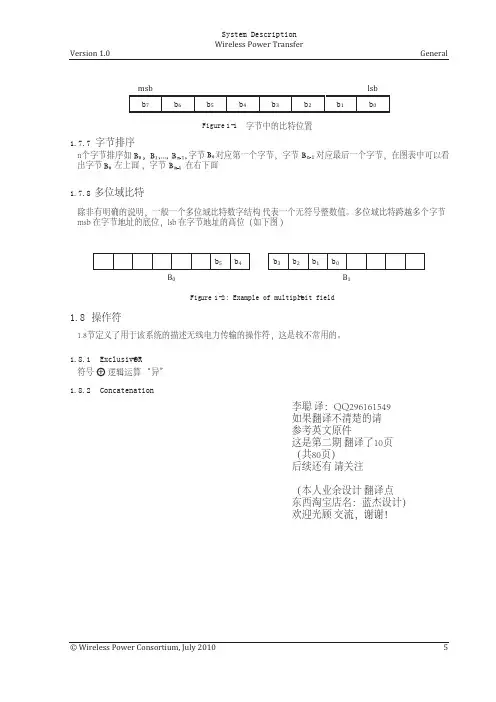
在一个字节。
1.7.6一点订购图示的一个字节就是这样,从事是左边,lsb在右边。
图1-1定义的点位置的字节。
1.7.7字节数这个字节序列中的氮字节被称为B0,B1,…,Bn-1。
B0字节的第一个字节的对应。
Bn-1字节序列对应;最后字节顺序。
图示的是这样的,B0字节序列在上面的左侧,字节Bn-1在较低的右边。
1.7.8 Multiple-bit领域除非不那样显示,多一点场数据结构描述一个无符号整型值。
在一个multiple-bit领域跨越多个字节,从事的multiple-bit场坐落在字节,最低的地址,这个领域的multiple-bit lsb位于字节以最高的地址。
(信息)图1-2提供的一个例子,两个字节6-bit领域。
18运营商。
这段180定义操作系统采用无线通信电源转换,描述了较常用。
常用的运营商他们平常的意义。
Exclusive-OR增加这个符号的”代表exclusive-OR操作。
1.8.2连续“| |’的符号代表着连续两个咬弦。
最终在一起的咬弦位于右边的操作从事直接跟lsb的左手边的操作。
2系统概要(信息)。
操作装置,符合本系统描述无线权力转移依赖平面线圈之间的磁感应强度。
区分两种装置,即装置提供无线power-referred为基础Stations-and设备,无线电力消耗,简称移动设备。
电力传输总是从一个基站到移动设备。
为了这个目的,一个基站包含一个subsystem-referred作为电力Transmitter-that包括一个初级线圈, 1和移动设备包含一个subsystem-referred来作为一种力量接收-包括一个次要线圈。
事实上,主要的线圈和二次线圈形成的两半芯共振的变压器。
适当的屏蔽的底部的脸线圈的顶面第二组线圈,以及近间距的两卷,确保电力传输时发生的可接受的效率。
此外,该屏蔽最小暴露的磁场。
通常,一个基站surface-referred具有扁平的Surface-on接口的一个用户可以把一个或更多的移动设备。
这保证了垂直的间距和线圈小学第二组线圈足够小。
除此之外,还有两个概念为横向对齐的初级线圈和二次线圈。
在第concept-referred为指导Positioning-the用户必须积极的第二次卷卷,放置在恰当的移动设备接口的位置。
为了这个目的,手机提供一个对齐的援助适当的大小、形状和功能。
第二concept-referred为自由Positioning-does不需要主动参与的初级线圈和二次线圈。
一个实施免费定位的数组的初级线圈产生的磁场第二组线圈的位置。
另一个实施免费定位采用机械即一个初级线圈下面第二卷。
图2-1的基本体系结构。
如图所示,一个功率发射机包含两个主要功能单元,即一个电源转换装置,而且沟通和控制单元。