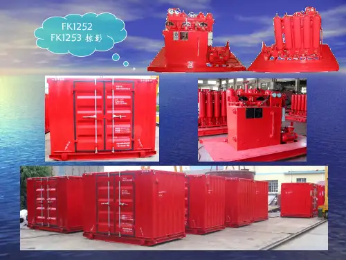
1253泵控制器中文使用手册
- 格式:pdf
- 大小:1.47 MB
- 文档页数:6
水泵操作说明一、前言水泵是一种用来运输液体的机械设备,广泛应用于工业、农业和民用领域。
本文将介绍水泵的操作步骤及注意事项,以确保安全高效地操作水泵。
二、准备工作1. 确保水泵所需的电源稳定可靠,并符合使用电压要求。
2. 检查水泵设备的连接管路、旋钮和阀门是否牢固,无渗漏情况。
3. 将水泵放置于平稳的地面或地基上,确保稳固。
4. 检查水泵的进水和出水口,确保没有堵塞或其他障碍物。
三、操作步骤1. 打开电源:将电源插头插入电源插座,并打开供电开关。
2. 检查运行方向:根据水泵的旋转方向箭头,确保电机和水泵的运行方向一致。
3. 开启进水阀:逐渐打开进水阀门,允许水进入水泵。
4. 启动水泵:按下启动按钮或开关,启动水泵设备。
5. 检查运行状态:观察水泵设备是否正常运转,并注意是否有异常噪音或振动。
6. 调整流量:根据实际需求,适当调整进水阀门的开度,控制水泵设备的流量。
7. 关闭水泵:当不再需要使用水泵时,首先关闭进水阀门,然后按下停止按钮或开关,停止水泵设备运转。
8. 断电:关闭电源开关,并拔掉电源插头。
四、注意事项1. 操作前务必熟悉水泵设备的使用说明和安全操作规程。
2. 在操作水泵前,应确保人员穿戴好必要的个人防护装备,如手套、安全鞋等。
3. 在启动水泵前,应检查周围环境是否存在易燃易爆物品,确保操作安全。
4. 切勿长时间运行水泵设备,以免引发设备过热或其他问题。
5. 定期检查水泵设备的油液、密封件以及电机等部件是否正常,并进行必要的维护和更换。
6. 在长时间不使用水泵时,应将水泵设备进行清洗、排干,并存放在干燥通风的地方。
7. 如遇突发情况或故障,请立即停止使用水泵,并寻求专业人士的帮助和维修。
五、结语正确操作水泵是确保其正常运行和延长使用寿命的重要一环。
通过遵循本操作说明,您可以安全高效地操作水泵设备。
如有任何疑问或需要进一步的帮助,请咨询专业人士或水泵设备厂家。
祝您工作顺利!。

水泵智能控制器说明书(总1页) -CAL-FENGHAI.-(YICAI)-Company One1
-CAL-本页仅作为文档封面,使用请直接删除
水泵智能控制器说明书
鋐祺牌水泵控制器是研究人员经过多年的潜心研究和反复试验开发的一种远距离控制水泵与开关的遥控装置。
水泵控制器接口说明:
水泵智能控制器操作说明:
1、按手动键启动水泵,水泵运行,任意键可停止水泵运行。
2、同时按下设置+手动键,听到蜂鸣器响声,然后按遥控器任意键,听到蜂鸣器响声,配对成功。
3、遥控器操作,遥控器侧面电源键打到ON位置,然后拉出天线,按遥控器开键启动水泵,按关键关闭水泵。
遥控器不使用时请将侧面电源开关拨到OFF位置,节省电池电源。
故障说明:
1、远距离遥控水泵不起作用,更换9V叠层电池。
2、380水泵控制器手动指示灯闪烁时,说明缺相,请检查电线是否接好。
2。
1253C泵控说明书Content目录1. Scope 应用场合This specification specifies the Curtis 1253C motor speed controllers which are designed for series pump motors. Its typical applications include the hydraulic systems of material handling vehicles and other industrial vehicles.SHINGKO 1253C电机速度控制器是为串励泵控电机而设计的。
广泛应用于液压系统的重型托盘车和其它工业车辆。
2. Description 概述1253C offers smooth, silent, cost effective motor speed and torque control according to the signals of lifting, tilt, power steering, sideward move (forward move). They will prolong the life of the motors, contactors, batteries and reduce maintenances of the systems as it greatly reduces high current impact.The output PWM can be programmed with speed select inputs SS1-SS4 and analog throttle input.So the 1253C controllers can ensure not only the lifting speed control but also the system stability and safety. These controllers are fully programmable by means of the 1311 programmer, with diagnostic and test capability. System status can also be indicated via an external LED.The 1253C controllers have completely protection functions such as current limit, reverse polarity protection, startup lockout, over voltage protection, low voltage protection, and so on. They can provide lift lockout fun ction with Curtis meters (such as 906, 803, ENGAGE IV) whe n battery is deep discharger.CAN communication feature is added to the 1253C, so it can work with other CAN devices such as CAN tiller head which will greatly simplify the wiring.1253C 根据上升、下降、转向、前进信号提供了平稳、安静、有效的电机速度和扭矩控制。
水泵控制柜操作
使用说明书
2013年9月15日制作设计
一.
1.、
、2.
3.
4.
二.
免水泵无水运行而造成水泵损坏。
1.手动-自动转换旋钮SA1在手动位置。
2.按下启动按钮1SB、2SB水泵运行,运行指示灯
1HG、2HG亮起。
3.按下停止按钮1SSB、2SSB水泵停止,运行指示
灯1HG、2HG熄灭。
4.故障时自动停泵,故障指示灯1HR、2HR亮起。
三.一控二自动控制
功能简介:控制柜接收五个水位信号(超停泵水
位、停泵水位、起单泵水位、起双泵
1.
2.1运
2 3.
4.
5.1
泵2不动作,收到超高水位信号时启动双泵。
6.泵1故障时泵1自动停止,并且自动切换到泵2
运行。
泵2故障时泵2自动停止,并且自动切换到
泵2运行。
四.BAS接口
本机与BAS通讯使用标准MODBUS-RTU协议,RS485通讯接口。
详情见附件记录:南京3号线BAS与车站排水泵接口功能测试大纲及记录.pdf
五.故障分析及排除
排除方法:修复故障或更换PLC
5.FU1熔断器保险丝熔断
分析:控制线路或到柜外的电缆有短路或漏电(浮球线缠绕破皮)
排除方法:查明线路受损短路处,更换保
险丝
6.PLC正常情况下BAS无法读取信号
分析:输出信号线接头松动,九针头子脱焊
排除方法:检查端子排X3的端子1、2电
六.。
1253C泵控说明书Content目录1. Scope应用场合This specification specifies the Curtis 1253C motor speed controllers which are designed for series pump motors. Its typical applications include the hydraulic systems of material handling vehicles and other industrial vehicles.SHINGKO 1253C 电机速度控制器是为串励泵控电机而设计的。
广泛应用于液压系统的重型托盘车和其它工业车辆。
2. Description 概述1253C offers smooth, silent, cost effective motor speed and torque control according to the signals of lifting, tilt, power steering, sideward move (forward move). They will prolong the life of the motors, contactors, batteries and reduce maintenances of the systems as it greatly reduces high current impact.The output PWM can be programmed with speed select inputs SS1-SS4 and analog throttle input. So the 1253C controllers can ensure not only the lifting speed control but also the system stability and safety. These controllers are fully programmable by means of the 1311 programmer, with diagnostic and test capability. System status can also be indicated via an external LED.The 1253C controllers have completely protection functions such as current limit, reverse polarity protection, startup lockout, over voltage protection, low voltage protection, and so on.They can provide lift lockout function with Curtis meters (such as 906, 803, ENGAGE Ⅳ) when battery is deep discharger.CAN communication feature is added to the 1253C, so it can work with other CAN devices such as CAN tiller head which will greatly simplify the wiring.1253C 根据上升、下降、转向、前进信号提供了平稳、安静、有效的电机速度和扭矩控制。
泵宝中⽂说明书⽔泵控制器⾮常感谢您选⽤⽔泵智能控制器,为了您正确使⽤本控制器,请在使⽤前仔细阅读本说明书,并妥善保存以供今后参考。
快速安装指南接线按控制器接线⽰意图,接好电源线和探头线。
过载设定将控制器内⾯板上的三档开关拨⾄“过载设置”,再左右调节控制器内⾯板上的电位器旋钮,调⾄您需设定的数值,空载设置指⽰灯会闪3下熄灯既表⽰设定ok。
试运⾏安装及设定完成后,按启动键试运⾏,试运⾏如还遇到其它困难,请详细阅读本说明书或与我司经销商联系!具体详细使⽤规则,以此说明书为准!注意事项注意事项1、安装本控制器时,⼀定要严格遵守国家电⼯操作规程,请勿带电作业,请专业电⼯安装,否则有可能出现触电事故!2、本控制器未装漏电保护开关,漏电⽆保护,可能引起严重的安全事故,请⽤户⾃⾏加装漏电保护装置。
3、如果本控制器未带空⽓开关,使⽤时必须增加空⽓开关,否则不能起到有效过载保护。
4、设定过载电流必须与电机正常⼯作电流相符,否则不能起到有效过载保护。
5、电机过载等故障后,务必先排除故障,再按启动键则重新启动。
如不排除故障,让电机启动,控制器和电机都很容易烧坏。
6、如电机频繁启动或超负荷⼯作,必须选⽤⽐电机功率⼤⼀个型号的⽔泵智能控制器,否则有可能烧坏电机或造成事故!7、本产品在⼀般情况下能起到保护作⽤(如过载等),能在部份情况下有效地保护电机,降低电机返修率,但不是所有情况下都能保护电机不被烧毁,例如:电机本⾝的质量问题或雷击等。
8、本公司只对本产品进⾏保修或维修,如⽤户使⽤本产品后,电机还出现故障或烧机,本公司不负责维修或赔偿!另外由于机器故障对⽤户造成的影响,本公司也不承担责任,例如:排污时由于机器故障造成地下室被淹等。
9、控制器安装环境要求:请安装在室内,避免太阳直接暴晒,或者淋⾬。
使⽤温度:-10℃⾄40℃湿度:相对湿度不⼤于90%海拔⾼度:不超过2000m探头线耐温:105℃01 使⽤安装说明书⼀、产品包装⽔泵智能控制器说明书探头安装螺丝及胶塞1台1本1套各3个⼆、产品特点采⽤数码芯⽚控制,集上、下液位和压⼒⾃动控制于⼀体具有⾃动、⼿动两种⼯作模式可供选择具有过载、空载、超低压等保护功能具有空载重启时间1~240分钟可调具有故障记忆功能,5次故障原因可能轻易查阅专利交流数码讯号检测功能,探头更耐⽤安装⽅⾯,调试简单三、主要技术参数1、静态功率⼩于3.5W,动态功率⼩于4.5W;2、出⼚默认值:A.过载设定默认值为:1.5KW为8A,2..2KW为11A;B.空载设定值为00.0A,空载保护后⾃动恢复时间为30分钟;3、最⼤控制距离:500⽶;4、过载保护反延时特性,时间误差为±15%:过载倍数 1.2倍 1.5倍2倍3倍5倍保护时间 50秒30秒15秒6秒1秒四、安装接线指南1、将控制器固定在墙壁上,打开接线盒,按标签提⽰接好电源、⽔泵。
四泵恒压供水系统的基本功能:
⑴供水时系统恒压运行。
⑵四台泵根据恒压的需要,采取先开先停的原则接入和退出。
⑶在用水量小的情况下,如果一台泵连续运行时间超过一天,则要切换下一台泵,系统具有倒泵功能,避免一台泵工作时间过长。
⑷完善的报警功能。
⑸对泵的操作手动只在应急或检修时使用。
输入输出点/代码及地址编号表1
2.1小泵工作逻辑
水压低于下限,起泵,水压高于上限延时2秒停泵。
2.2变频大泵工作逻辑
2.2.1小泵起泵运行状态下,水压低持续60秒后:停小泵,起动1台变频大泵,变频大泵恒压工作,直到水压高于上限延时2秒停泵。
2.2.2 1台大泵变频起泵运行状态下,水压低持续60秒后:停当前变频泵,当前变频泵转工频运行,下1台大泵变频起动运行。
2.2.31台大泵工频,1台大泵变频起泵运行状态下水压低持续60秒后,停当前变频泵,当前变频泵转工频运行,下一台大泵变频起动运行,30秒后水压仍低,全体停泵。
2.2.4水压高于上限延时1秒后:停工频大泵。
2.2.5水压高于上限延时2秒后:停变频大泵。
2.3大泵倒泵逻辑
如单台变频运行每运行1小时,自动倒到下1台。
2.4低水位逻辑
停机,报警,待水位恢复后5分钟后,自动恢复运行。
2.5变频故障逻辑
停机,报警,变频器复位后,自动恢复运行。
2.6自动无法正常使用
手动方式起动运行。
3应急使用
3.1如有泵损坏,关闭相应回路开关。
3.2 小泵损坏,直接使用大泵变频恒压,如大泵不能正常恒压,修改变频器参数E10上限频率,适当降低,小泵正常后将参数改回。
水泵操作说明及注意事项一、操作说明1.1控制方式a.“本地/集控”选择:当开关至“本地”位置时,“一水平”及上位机只能操作其本地各水泵排水,不能控制“二水平”水泵排水,“二水平”可在其本地操作各水泵排水;当开关至“集控”位置时,“一水平”及上位机可在本地操作台操作“二水平”各水平排水,“二水平”可在其本地操作各水泵排水。
b.“自动/手动/遥控”选择:当开关至“自动”位置时,依靠液位传感器实时检测液位,与触摸屏设置的“启泵液位”比较,若实时液位大于或等于启泵液位时,系统自动启动预定的水泵来排水,直到实时液位小于或等于“停泵液位”时自动停泵;当开关至“手动”位置时,水泵排水由人工手动来操作;当开关至“遥控”位置时,地面调度中心的上位机可进行远程操作水泵排水。
说明:不管“自动/手动/遥控”选择开关至其中任一位置,本地操作台都能进行操作,确保就地优先级。
c.“正常/检修”选择:当开关至“正常”位置时,操作人员可正常操作水泵排水;当开关至“检修”位置时,地面上位机界面显示“系统正在检修,严禁启泵操作”,此时操作人员严禁启动水泵排水。
d.真空泵的“1#/2#”选择:作为当前所使用的真空泵切换选择。
e.“正常/应急”选择:当开关至“正常”位置时,出现故障后,操作台显示故障信息,并报警;当开关至“应急”位置时,屏蔽系统“轻微故障”(主电机过压欠压、水泵及电机超温、流量过低、水槽液位过高等)报警,但“重大故障”(正压异常、软起失败等)不屏蔽。
1.2 启、停泵控制按键a.1#1启动:表示启动一水平的第一台泵(靠近一水平变电所)。
b.1#1停止:表示停止一水平的第一台泵(靠近一水平变电所)。
c.2#1启动:表示启动二水平的第一台泵(靠近二水平变电所)。
d.2#1停止:表示停止二水平的第一台泵(靠近二水平变电所)。
水泵编号水平代号水平编号1.3 其他按键a. “1#故障复位”钮:表示一水平故障复位按钮;“2#故障复位”钮:表示二水平故障复位按钮。
1253C泵控说明书Content目录1. Scope应用场合This specification specifies the Curtis 1253C motor speed controllers which are designed for series pump motors. Its typical applications include the hydraulic systems of material handling vehicles and other industrial vehicles.SHINGKO 1253C 电机速度控制器是为串励泵控电机而设计的。
广泛应用于液压系统的重型托盘车和其它工业车辆。
2. Description 概述1253C offers smooth, silent, cost effective motor speed and torque control according to the signals of lifting, tilt, power steering, sideward move (forward move). They will prolong the life of the motors, contactors, batteries and reduce maintenances of the systems as it greatly reduces high current impact.The output PWM can be programmed with speed select inputs SS1-SS4 and analog throttle input. So the 1253C controllers can ensure not only the lifting speed control but also the system stability and safety. These controllers are fully programmable by means of the 1311 programmer, with diagnostic and test capability. System status can also be indicated via an external LED.The 1253C controllers have completely protection functions such as current limit, reverse polarity protection, startup lockout, over voltage protection, low voltage protection, and so on.They can provide lift lockout function with Curtis meters (such as 906, 803, ENGAGE Ⅳ) when battery is deep discharger.CAN communication feature is added to the 1253C, so it can work with other CAN devices such as CAN tiller head which will greatly simplify the wiring.1253C 根据上升、下降、转向、前进信号提供了平稳、安静、有效的电机速度和扭矩控制。
规格- PWM 工作频率: 15.6KHz- 绝缘: 500VAC(最小)- KSI 输入静态电流(主接触器断开): 不带编程器时<60mA , 带编程器时<130mA - 逻辑信号输入电流: <1mA- 工作环境温度: -40℃~50℃ - 储存环境温度: -40℃~85℃- 温度保护: 80℃(保护起始点)-120℃(限流关断点)- 温度低于-25℃时,最大限流值为原设定值的50%。
- 重量: 2.6kg- 接触器线圈驱动能力: 1A(最大) - 故障指示LED 驱动电流: 5mA.(最大) - 防护等级:IP54型号 额定电压(VDC) 限流(A) KSI 输入电压(VDC) 欠压 (可编程设定) (VDC) 过压关断 (VDC) 1253-48xx48 600 28~60 32~42 60 1253-80xx8060047~10254~70102特性- 无电弧操作 - 可编程- 加速器类型可为单端或摇摆型5K 电位器; 0-5V 霍尔型加速器 - SS1-SS4四路速度选择输入,每路最大速度可编程 - SS4用于转向助力时可提供延时功能 - 最小速度可编程- 通过1311编程器实现自我测试和诊断功能 - 故障码 LED 输出提供故障诊断功能- 顺序选择(Startup lockout)功能防止启动时的错误操作 - 温度保护功能 - 过/欠压保护 - 预充电控制- 软硬件看门狗保证程序正常运行- 配合CURTIS 仪表906,803,enGage ,SuperSpy 可提供提升锁止功能 - 提升锁止输入信号类型可编程设定,从而适应不同的提升锁止输入信号。
- 接触器驱动输出控制 -接触器驱动短路保护尺寸接线图图1 接803仪表,控制器LOCKOUT TYPE设为1,当电池放电超过80%时,803仪表3,4脚断开,控制器将触发提升锁止功能,禁止输出。
图2 接906仪表,控制器LOCKOUT TYPE设为0,当电池放电超过80%时,906仪表3脚由5V变为0,控制器将触发提升锁止功能,禁止输出。
1253泵控制器中文使用手册1253泵控制器中文使用手册1.引言1.1 文档概述本手册旨在提供有关1253泵控制器的详细信息,包括其功能、安装、操作和维护等方面的指导。
1.2 目标读者本手册面向所有使用1253泵控制器的人员,包括操作员、安装人员和维护人员等。
1.3 重要提示在使用本产品之前,请仔细阅读本手册并按照其指导进行操作。
如果有任何疑问或问题,请联系我们的技术支持团队。
2.产品概述2.1 产品概述1253泵控制器是一种先进的设备,用于控制和监测水泵的运行状态和性能。
2.2 主要特点- 具有多种输入和输出接口,可连接多种传感器和执行器。
- 支持多种控制模式,如手动、自动和远程控制。
- 提供了详细的运行参数和故障诊断功能。
3.安装与连接3.1 安装前准备在安装本产品之前,请确保您已经具备以下条件: - 安装地点符合相关安全规范。
- 已准备好所需的工具和材料。
3.2 安装步骤1.将1253泵控制器安装在合适的位置,并固定好。
2.将电源线连接到控制器上,并将其接通电源。
3.根据所需连接的传感器和执行器类型,连接相应的接口。
4.操作指南4.1 控制器界面介绍4.1.1 显示屏控制器配备了一个易于阅读的显示屏,用于显示各种运行参数和故障信息。
4.1.2 按钮控制器具有一组按钮,用于进行各种操作,如模式选择、参数调整和启停控制等。
4.2 基本操作流程1.按下电源按钮,控制器开始运行。
2.根据需要选择相应的控制模式。
3.根据实际情况调整相关参数。
4.根据需要启停水泵或进行其他操作。
5.维护与故障排除5.1 维护要求5.1.1 定期检查每隔一段时间,需要对控制器进行定期检查,以确保其正常运行。
5.1.2 清洁定期清洁控制器,特别是接口和按钮部分,以防止灰尘和污垢积累。
5.2 常见故障排除5.2.1 无法启动水泵- 检查电源是否正常接通。
- 检查控制器是否设置为正确的工作模式。
- 检查水泵本身是否故障。
5.2.2 显示屏无法显示信息- 检查电源是否正常接通。
CHEAT SHEETFEATURES & BENEFITS • IP54 engineered plastic enclosure - complete protection against contact with live or moving parts inside the enclosure. Protection against harmful deposits of dust. The ingress of dust is not totally prevented, but cannot enter in an amount sufficient to interfere with satisfactory operation of the machine. Water splashed against the enclosure from any direction shall have no harmful effect.• Intelligent real time LCD displays pump running information for ease of diagnostics so you can see what is going on with the pumps.• Intelligent push button pump overload calibration prompts for incomplete calibration to guarantee that the pump current is set correctly protecting the pump from overload and dry running.• Function switch setting for drainage, pressure boosting or transfer applications for easy adjustment to suit the application required.• Level controls can be float switches or probes for versatile and customisable installation.• Auto, manual switching so you can choose how it works. You can switch it to manual to empty the sump for servicing or repairs.• Visible and audible alarms to better alert you if an issue arises.• Adjustable time delay for audible alarm allows you to determine how long the alarm sounds for.• Low voltage control circuit for safety the iCON control has a built in transformer so it only provides low voltage to the floats, pressure switches etc.• RS485 communication interface (BMS, MODBUS) using a hardwired paired wire to a management system to communicate to the controller remotely.• Pump accumulated run time display to monitor the run duration and assist in determining age of the pumps based on service.• Last five pump faults if any logged into memory for better diagnostics if there has been a recurring problem with a particular pump.• Slave controller included to be able to control the unit (everything except pump calibration and parameter setting) up to a max 1.2km from the main pump controller using STP – shielded twisted pair cable (not included).• Control box contains MCB and DOL contactor to be able to turn the unit off to allow for servicing of pumps • Provision for combinations of multiple device inputs and outputs for use with float switches, probes, pressure switches or external device alarms for versatility of application.• In addition to the features listed above the dual pump controller (DPC) also has alternating pump starts andAutomatic dry pump cycling (Anti Seize) and load sharing to extend the life of the pumps.An iCON Series Control is an intelligent, easy to use management system for various pump situations.Used when you need to control the pump or pumps in different applications.It can give you real time information on the performance of the pumps.It will show you the last 5 error codes (if any) for each of the pumps.IT PROTECTS THE PUMP .Distributed By:.au WHITE INTERNATIONAL PTY LTD60 Ashford Ave Milperra NSW 2214 PO Box 304 Milperra NSW 2214Customer Service 1300 783 601EmailSales:**********************.au .au WHITE INTERNATIONAL NZ LTD 15G Kerwyn Avenue East Tamaki, Auckland 2013, New Zealand Customer Service 0800 509 506EmailSales:*****************.nz APPLICATIONSDRAINAGE WITH AUTOMATIC PUMPS •Applied for drainage (where pumps have their own float switches)•Mainly used in instances where float cables can’t be run through the conduit from the sump to the control panel. •Generally because the builder has not laid a conduit large enough to fit: 2 x pump power leads and 3 x float cables.• All that is required are the pump power leads and one floatcable (overflow)BOOSTING • Applied for water supply by pressure control through pressure switch and pressure tank • High Rise Buildings • Hotels • Hospitals • Shopping Centres • Used in conjunction with a vertical multistage booster pump. The impellers boost the pressure of the water as it passes through to have enough pressure to service either a greater demand for water or a greater height than would otherwise be possible.•Instead of floats, pressure switches are connected to thecontrol panel to manage the pumps.TRANSFER •Applied for water supply or drainage by liquid level control through float switch or liquid sensor • Dam to Water Tower • Tank to Tank •Generally used when you need to move water from one location to another.•The float switches are installed in both the source and destination of the water storages. • iCON controller will only allow water to go to the destination ifit is needed and the source has water to accommodate.HOT WATER CIRCULATION • Applied for water supply by the thermal switch • High Rise Buildings • Hotels • Hospitals • Shopping Centres • Under Floor Heating • The hot water line must have a return line installed for a circulator pump to work.• If a thermostat is used you can set the temperature to kick in the circulator pumps to bring the cold water back to the boiler so that it is replaced by hot water.• Used in situations where it is inconvenient or impractical towait for hot water to come through the pipes.DRAINAGE • Applied for drainage by liquid level control through float switch or liquid probe • Flooding • Stormwater • Moves excess water from a primary location elsewhere.• In conjunction with the float switches or probes the iCON controller switches the pumps on and off as required to emptythe sump.PROGRAMME iCON CONTROLLER • Check that the pumps have been installed correctly as per the instruction manual for the desired application.• Check that the control panel is disconnected from the power supply and wait 2 minutes before opening the control panel.connect the power supply.• Calibrate the controller to the pumps.• Fill the sump with enough water to be able to start the pumps.• Press MODE and STORE keys together to unlock the controller and switch it to manual mode.•Press A START key to run pump A and confirm that the pump and all pipe network is in a normal working state.•Press the STORE button. The control panel will make a beep sound and a countdown starts from 5 to 0 with the LCD displaying:•Press B START key to run pump B and confirm that the pump and all pipe network is in a normal working state.•Press the STORE button. The control panel will make a beep sound and a countdown from 5 to 0 starts again.• Press MODE to return to automaticHOW DOES IT PROTECT PUMPS?•The controller itself will determine based on the pump calibration if anything is going on that requires attention.•There will be an audible and visible alarm to alert you of a problem.• Press A STOP to turn off the alarm for 5 minutes.• Read what is on the display.PROGRAMMINGCHANGING PARAMETER SETTINGS • Ensure panel is in manual and pumps are not running.• Press MODE for 5 seconds until the controller beeps and the first parameter will be displayed.• Press MODE to select to select the parameter code required.• Press A START to increase the value and A STOP to decrease the value.• Press MODE to select to select the next parameter code if required.• When completed press MODE for 5 seconds until the controller beeps.TROUBLESHOOTING PUMP NO CALIBRATION• Pump no calibration is flashing• Fill the sump with enough water to be able to start the pumps.• Press MODE and STORE keys together to unlock the controller and switch it to manual mode.• Press A START key to run pump A and confirm that the pump and all pipe network is in a normal working state.• Press the STORE button. The control panel will make a beep sound and a countdown starts from 5 to 0.• Press B START key to run pump B and confirm that the pump and all pipe network is in a normal working state.• Press the STORE button. The control panel will make a beep sound and a countdown from 5 to 0 starts again.• Press MODE to return to automaticOVERLOAD OR PUMP STALLED• Overload or pump stalled is flashing.• Pumps may not have been calibrated properly• Remove previous calibration by:• Switching it to manual mode (MODE & STORE)• Press A STOP for 30 seconds until the panel beeps. Pump A no calibration should be displayed.• Press B STOP for 30 seconds until the panel beeps. Pump B no calibration should be displayed.• Calibrate the pumps one at a time by pressing START let the pump run and then STORE.• Return to automatic by pressing MODE.OVERTEMP• Overtemp is flashing.• The red jumper leads between terminals 10 and 12, (and 9 and 11 for dualpumps) has been removed.• Replace the leads – unless there is a set of pump microtherm wires to connect.DRY RUN• Check that the float switches are not set too low, or if they are caught up inside the tank allowing air into the pumps.• For surface mounted pumps, ensure that the pumps are primed and that any valving is open to allow flow into the pumps.REPEATED START• This will flash if there are more than 5 starts per minute.• Usually occurs on pressure systems. Check the tank pre-charge and bladder, pressure switch settings or defects.• Pumps may be oversized or have flat performance curves.UNDER V or OVER V• Voltage is out of range.• The pump will attempt to restart every 5 minutes until voltage is restored to normal.• If it is unresolved, please discuss with the product managerPHASE REVERSAL• 3 Phase only• Incoming phase rotation has changed from when control panel was originally connected.• When connecting pump rotation during commissioning, the pump connections must be changed, NOT the incoming power connection.• If this has occurred, change the incoming connections and the pump connections together. NETWORK CONNECTION ERROR• This is normal if the slave controller is not installed.• If the slave controller has been installed and the error message appears, it means that there is no network connection or a connection error between the pump control box and the slave controller(or computer).。
LC系列高效烟气脱硫循环泵安装使用说明书注意□请仔细阅读本说明书,理解各项内容,以便能正确安装、运行、操作和保养维护等。
□本说明书应保存在实际最终使用人的手中。
□开车前必须重新调试泵的安装状态,并由泵生产产家确认□本产品技术规范可能发生变化,恕不另行通知。
襄樊五二五泵业有限公司公司简介襄樊五二五泵业有限公司原为中国兵器工业集团五二五厂所属企业,一九九九年九月改制为有限公司。
公司注册于襄樊(国家级)高新技术产业开发区。
湖北省高新技术企业,ISO9001质量体系认证企业,中国通用机械泵行业协会会员,中国磷肥、硫酸工业协会会员,中国化工装备总公司供货定点企业。
公司现有资产总额3000万元,员工200多名,专业技术人员50余人。
三十多年来我公司坚持自主开发和引进技术相结合,引进了法国J.S/H.S公司的LC系列泵专有制造技术,并在引进技术的基础上,适应市场需求,自主开发了多种泵型。
公司生产的主要产品有:LC系列卧式离心泵、LC系列高效烟气脱硫循环泵、PLC系列立式离心泵、LC-T系列渣浆泵、PLC-T系列立式渣浆泵、LH系列重型渣浆泵、FYL系列悬臂立式离心泵、IHE系列化工流程泵、LB系列化工流程泵、IHZ 系列化工自吸泵、HZ系列化工轴流泵、LHZ系列立式轴流泵、MECP系列混流泵、S 型系列双吸泵、LSD系列高温浓硫酸泵以及截止阀、球阀等近两百种规格。
生产的材料有1Cr18Ni9Ti、304、304L、316、316L、Mo2Ti、904(UB-6)、C4、Cr30A、2605N、CD4MCu、DF2、MM-4、K合金、SS920、20#合金、哈氏合金、蒙乃尔合金等二十多种。
产品广泛用于化工、化肥、冶金、矿山、火电、医药、造纸、污水处理等行业。
同时能根据用户的要求,提供大、中型不锈钢铸件和耐磨材料铸件,并承接来图加工制作。
主要技术装备:采用美国亚什兰工艺PEPSET树脂自硬砂造型生产线、采用中频炉熔炼,最大铸件重量可达3.0吨、采用光谱分析仪和红外碳硫分析仪对钢水进行快速分析、热处理炉采用电子程序控制、泵的转子采用动平衡测试技术、符合ISO2548要求的B级精度的泵性能测试系统、采用计算机辅助设计。
水泵控制器使用说明书1. 引言水泵控制器是一种用于自动控制水泵运行的设备,通过监测水位、压力等参数,实现对水泵的自动启停和保护功能。
本使用说明书将详细介绍水泵控制器的组成部分、安装方法、操作说明以及常见故障排除方法,以便用户正确、安全地使用水泵控制器。
2. 组成部分水泵控制器主要由以下几个部分组成:- 控制面板:提供操作按钮和显示屏,用于设置水泵的工作参数和显示运行状态。
- 检测传感器:用于监测水位、压力等运行参数,将信号传输给控制面板。
- 继电器:通过控制面板的指令,实现对水泵电机的启停控制。
- 保护装置:包括过压保护、欠压保护、短路保护等功能,保证水泵运行的安全性。
3. 安装方法3.1 准备工作在安装水泵控制器之前,确保完成以下几项准备工作:- 确定水泵的安装位置,并保证周围环境通风良好。
- 确保水泵的电源和接地符合安全要求。
- 检查水泵的接线是否正确,确保无误。
3.2 安装步骤1) 将水泵控制器固定在合适的位置,可采用螺丝固定或安装在控制柜中。
2) 将水泵的电源线与水泵控制器的电源接线端子相连。
3) 根据实际情况,连接水泵控制器与水泵电机的控制线路。
4) 将水位、压力等传感器正确接入水泵控制器的检测端子。
5) 检查所有接线,确保连接牢固可靠。
6) 接通电源,完成水泵控制器的安装。
4. 操作说明4.1 启动水泵1) 打开水泵控制器的电源,显示屏将显示当前的工作状态。
2) 按下启动按钮,水泵电机将开始工作。
3) 此时,水泵控制器将自动监测水位、压力等参数,并根据设定值进行调整。
4.2 停止水泵1) 按下停止按钮,水泵电机将停止工作。
2) 水泵控制器将停止监测参数,并进入待机状态。
4.3 参数设置1) 在水泵控制器的显示屏上,按下设置按钮,进入参数设置界面。
2) 根据实际需要,设置水位、压力等参数的上下限,以及启停水泵的延迟时间等。
3) 设置完成后,按下确认按钮保存设置。
5. 常见故障与排除方法5.1 水泵无法启动可能原因及排除方法:- 检查电源线是否连接正确,确保电源正常供电。
规格- PWM 工作频率: 15.6KHz- 绝缘: 500VAC(最小)- KSI 输入静态电流(主接触器断开): 不带编程器时<60mA , 带编程器时<130mA - 逻辑信号输入电流: <1mA- 工作环境温度: -40℃~50℃ - 储存环境温度: -40℃~85℃- 温度保护: 80℃(保护起始点)-120℃(限流关断点)- 温度低于-25℃时,最大限流值为原设定值的50%。
- 重量: 2.6kg- 接触器线圈驱动能力: 1A(最大) - 故障指示LED 驱动电流: 5mA.(最大) - 防护等级:IP54型号 额定电压(VDC) 限流(A) KSI 输入电压(VDC) 欠压 (可编程设定) (VDC) 过压关断 (VDC) 1253-48xx48 600 28~60 32~42 60 1253-80xx8060047~10254~70102特性- 无电弧操作 - 可编程- 加速器类型可为单端或摇摆型5K 电位器; 0-5V 霍尔型加速器 - SS1-SS4四路速度选择输入,每路最大速度可编程 - SS4用于转向助力时可提供延时功能 - 最小速度可编程- 通过1311编程器实现自我测试和诊断功能 - 故障码 LED 输出提供故障诊断功能- 顺序选择(Startup lockout)功能防止启动时的错误操作 - 温度保护功能 - 过/欠压保护 - 预充电控制- 软硬件看门狗保证程序正常运行- 配合CURTIS 仪表906,803,enGage ,SuperSpy 可提供提升锁止功能 - 提升锁止输入信号类型可编程设定,从而适应不同的提升锁止输入信号。
- 接触器驱动输出控制 -接触器驱动短路保护尺寸接线图图1 接803仪表,控制器LOCKOUT TYPE设为1,当电池放电超过80%时,803仪表3,4脚断开,控制器将触发提升锁止功能,禁止输出。
图2 接906仪表,控制器LOCKOUT TYPE设为0,当电池放电超过80%时,906仪表3脚由5V变为0,控制器将触发提升锁止功能,禁止输出。
触发提升锁止功能,禁止输出。
提升锁止功能,禁止输出。
1311 编程器编程菜单PARAMETER RANGE DEFAULTSETTING ACCESSLEVELSTEP DESCRIPTIONSS1 SPEED 0%~100% 25% User 1% SS1速度选择信号开关闭合允许输出的最大PWMSS2 SPEED 0%~100% 25% User 1% SS2速度选择信号开关闭合允许输出的最大PWMSS3 SPEED 0%~100% 25% User 1% SS3速度选择信号开关闭合允许输出的最大PWMSS4 SPEED 0%~100% 25% User 1% SS4速度选择信号开关闭合允许输出的最大PWMTHRTL MAX SPD 0%~100% 25% User 1% 加速器允许输出的最大 PWMMINIMUM SPEED 0%~50%0% User 1% 驱动电机的最小PWM值ACCEL RATE 0.2s~3.0s 1.0s User 0.2s 驱动电机的PWM从0%增加到100%的时间(s)SS ADD MODE ON/OFF ON OEM 速度选择开关:ON:叠加模式(add mode),OFF:first-on 模式FINAL ADD MODE ON/OFF ON OEM For Final SS and throttle; ON: add mode; OFF: first-on mode?THRTL FAULT ON/OFF OFF OEM 加速器故障检测; ON:允许加速器故障检测;OFF:禁止加速器故障检测THROTTLE TYPE 0~3 0 OEM 1 0: 0~5K, 2 线电位计1: 5K~0, 2 线电位计2: 单端 0~5V输入3: 单端3线电位计 (1-10K)THRTL DEADBAND 0~30% 10% OEM 1% 加速器中位死区范围THROTTLE MAX 60-100% 90% OEM 1% 最大PWM输出的加速器位置THROTTLE MAP 20~80% 50% OEM 5% The map of output PWM to throttle input?SS1 LIFT LOCK ON/OFF OFF OEM ON表示允许SS1信号的锁止功能,OFF表示禁止SS1信号的锁止功能SS2 LIFT LOCK ON/OFF OFF OEM ON表示允许SS2信号的锁止功能,OFF表示禁止SS2信号的锁止功能SS3 LIFT LOCK ON/OFF OFF OEM ON表示允许SS3信号的锁止功能,OFF表示禁止SS3信号的锁止功能SS4 LIFT LOCK ON/OFF OFF OEM ON表示允许SS4信号的锁止功能,OFF表示禁止SS4信号的锁止功能THRTL LIFTLOCK ON/OFF OFF OEM ON: 允许加速器的提升锁止OFF: 禁止加速器的提升锁止LOCKOUT TYPE 0~3 0 OEM 1 0表示低电平锁止,高电平及悬空不锁止;1表示高电平及悬空锁止,低电平不锁止;2表示高电平锁止,低电平及悬空不锁止;3表示低电平及悬空锁止,高电平不锁止. PRECHARGE ON/OFF ON OEM ON表示允许对电容进行预充电,OFF表示禁止预充电*STARTUP LOCK 0,1,2 1 OEM 1 0:无STARTUP LOCK功能;1: KSI型STARTUP LOCK 功能;2: KSI+INTERLOCK型STARTUP LOCK功能CONTACT CNTRL ON/OFF ON OEM ON: 主接触器受EVC255控制器控制*OFF:主接触器受外部控制SS4 DELAY 0.0s~60.0s 0.0s OEM 0.5s SS4开关断开后关闭对应于SS4信号的PWM输出的延时时间INTERLOCK DLY 0.0s~60.0s 5.0s OEM 0.5s INTERLOCK开关断开后关断驱动电机的PWM的延时时间LOVOLT CUTBACK 32 ~42V@48V model54~70@80V model 36V@48Vmodel60V@80VmodelOEM 0.5V 欠压起始值LOVOLT CB RATE 0~20 3 OEM 1 Low voltage cutback rate?CONT PULL IN 18~60V@48VDC30~100V@80VDC 48.0V@48VDC80V@80VDCOEM 0.5V@48VDC1V@80VDCContactor pull in voltage?CONT HOLDING 12.0~60.0V@48VDC20~100V@80VDC 48.0V@48VDC80V@80VDCOEM 0.5V@48VDC1V@80VDCContactor holding voltage?预充电控制和预充电故障检测依据下述参数设置。
参数设置 CONTACT CNTRL PRECHARGE 是否开启预充电功能 是否开启预充电故障检测功能 OFF ON YES YES OFF OFF YES NO ON ON YES YES ON OFF NONO1311 编程器测试菜单故障码状态码 状态灯 含义可能原因 LED OFF 灭 没有电压或者控制器不工作 Solid ON 常亮 控制器出错(如MCU 故障等)0,1 ■ ¤ 控制器正常工作,没有已知的故障1,1¤ ¤EEPROM 故障1.EEPROM 数据丢失或损坏2.EEPROM 数据效验错误用1311编程器改变控制器任何一个参数可消除此错误。
1,2 ¤ ¤¤ 硬件故障 1.MOSFET 短路 2.电机开路 1,3 ¤ ¤¤¤ 电机短路 电机短路2,1 ¤¤ ¤ 深度欠压 电池电压 < 欠压关断值2,2 ¤¤ ¤¤ 提升锁止1.触发了控制器的提升锁止功能。
2. SS 提升锁止参数设置不正确.2,3¤¤ ¤¤¤顺序故障(Startup lockout)1.加速器/SS 输入和 KSI 或Interlock 输入顺序错误2.Startup lockout 类型选择错误3.加速器调节错误2,4 ¤¤ ¤¤¤¤ 加速器故障1.加速器接线故障(开路或短路)2.加速器产品缺陷3.加速器类型选择错误3,1 ¤¤¤ ¤ CONT DRVR OC 接触器线圈短路3,2¤¤¤ ¤¤接触器粘结1.主接触器粘结2.参数"CONTACT CNTRL" 设置不正确3.主接触器短路3,3 ¤¤¤ ¤¤¤ 预充电故障1.预充电电路工作不正常3,4¤¤¤ ¤¤¤¤主接触器未装或者不闭合(DNC)1.主接触器线圈连接松动2.主接触器工作不正常3. CONTACT CNTRL 参数设置不正确t 4,1 ¤¤¤¤ ¤ 电池电压过低1.电池电压< LOVOLT CUTBACK 设定值2.电池端子腐蚀3.电池或控制器端子连接松动参数名级别 含义 HEATSINK TEMP User 散热器温度 CAP VOLTAGE User 电容电压 BATT VOLTAGE User 电池电压(KSI ) MOTOR VOLTAGE User 电机电压 THROTTLE% User 加速器信号 MAIN CONT DRVR User 主接触器驱动输出 DUTY CYCLE % User 加到电机上的脉宽SS1 INPUT User ON 表示SS1开关闭合,OFF 表示SS1开关断开 SS2 INPUT User ON 表示SS2开关闭合,OFF 表示SS2开关断开 SS3 INPUT User ON 表示SS3开关闭合,OFF 表示SS3开关断开SS4 INPUTUser ON 表示SS4开关闭合,OFF 表示SS4开关断开 LIFTLOCK INPUT User ON 表示锁止信号有效,OFF 表示锁止信号无效INTERLCK INPUTUserON 表示INTERLOCK 开关闭合,OFF 表示INTERLOCK 开关断开4,2 ¤¤¤¤ ¤¤ 过压 1.电池电压 > 过压关断设定值2.充电器工作控制器未断开4,3 ¤¤¤¤ ¤¤¤ 温度保护 1.控制器温度大于 85 C 或小于 -25 C2 泵电机负载过大3.控制器安装不正确4.在极端环境下工作5.温度传感器故障1311 编程器诊断菜单故障参数名含义THERMAL CUTBACK 温度保护(过温或低温)LOW BATTERY VOLTAGE 欠压保护LIFT LOCKOUT 提升锁止THROTTLE FAULT1 加速器故障SEQUENCE ERROR 顺序故障 (Startup lockout)OVERVOLTAGE 过压保护UNDER VOLTAGE CUTOFF 深度欠压EEPROM FAULT EEPROM 故障CONT DRVR OC 接触器线圈短路MOTOR SHORTED 电机短路MAIN CONT DNC 接触器不闭合MAIN CONT WELDED 接触器粘结PRECHARGE FAULT 预充电故障HW FAILSAFE 硬件故障。