射线检测典型缺陷图_共4篇(4)裂纹篇
- 格式:doc
- 大小:9.04 MB
- 文档页数:19
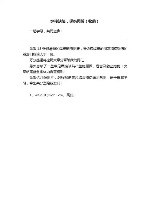
焊接缺陷,探伤图解(收藏)一起学习,共同进步!先看18张很清晰的焊接缺陷图谱,身边搞焊接的朋友和搞探伤的朋友们应该人手一份。
万分感谢将这篇文章分享给我的同仁另外总结了一些常见焊接缺陷产生的原因、危害及防止措施!文章结尾蓝色字体内容更精彩!先看这几张图片,射线探伤底片结合横切面示意图,便于理解学习,拿出来分享给朋友们!1、weld01(High Low、高低)2、welld02(IncompleteRootFusion、根部未熔合)3、welld03(InsuffucientReinforcement、增强高)4、welld04(Excess RootPenetration、根部焊瘤)5、welld05(ExternalUndercut、外部咬肉)6、welld06(InternalUndercut、内部咬肉)7、welld07(RootConcavity、根部凹陷)8、welld08(BurnThrough、烧穿)9、welld09(Isolated SlagInclusion、单个的夹渣)10、welld10(WagonTrack Slag Line、线状夹渣)11、welld11(InterrunFusion、内部未熔合)12、welld12(Lack ofSidewallFusion、内侧未熔合)13、welld13(Porosity、气孔)14、welld14(Cluster Porosity、链状气孔)15、welld15(HollowBead、夹珠)16、welld16(Transverse Crack、横向裂纹)17、welld17(CenterlineCrack、中心线裂纹)18、welld18(RootCrack、根部裂纹)常见焊接缺陷产生原因、危害及防止措施一、焊接缺陷的分类焊接缺陷可分为外部缺陷和内部缺陷两种1.外部缺陷1)外观形状和尺寸不符合要求;2)表面裂纹;3)表面气孔;4)咬边;5)凹陷;6)满溢;7)焊瘤;8)弧坑;9)电弧擦伤;10)明冷缩孔;11)烧穿;12)过烧。
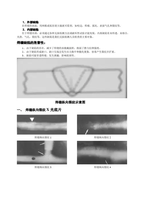
1.外部缺陷在焊缝的表面,用肉眼或低倍放大镜就可看到,如咬边,焊瘤,弧坑,表面气孔和裂纹等。
2.内部缺陷位于焊缝内部,必须通过各种无损检测方法或破坏性试验才能发现。
内部缺陷有未焊透,未熔合,夹渣,气孔,裂纹等,这些缺陷是我们无损检测人员检查的主要对象。
焊缝缺陷的危害性:1、由于缺陷的存在,减少了焊缝的承载截面积,削弱了静力拉伸强度。
2、由于缺陷形成缺口,缺口尖端会发生应力集中和脆化现象,容易产生裂纹并扩展。
3、缺陷可能穿透焊缝,发生泄漏,影响致密性。
焊缝纵向裂纹示意图一、焊缝纵向裂纹X光底片焊缝纵向裂纹1 焊缝纵向裂纹2焊缝纵向裂纹3 焊缝纵向裂纹4焊缝纵向裂纹5 焊缝纵向裂纹6焊缝纵向裂纹7 焊缝纵向裂纹8焊缝纵向裂纹9 焊缝纵向裂纹10焊缝纵向裂纹11 焊缝纵向裂纹12焊缝纵向裂纹13 焊缝纵向裂纹14焊缝纵向裂纹15 焊缝纵向裂纹16焊缝纵向裂纹17 焊缝纵向裂纹18焊缝纵向裂纹19 焊缝纵向裂纹20 纵向裂纹的表面特征是沿焊缝长度方向出现的黑线,它既可以是连续线条,也可以是间断线条。
纵向裂纹影像产生的原因是沿焊缝长度破裂而导致的不连续黑线。
二、热影响区纵向裂纹X光底片热影响区纵裂1 热影响区纵裂2 热影响区撕裂呈线性黑色锯齿状,平行于熔合线,穿晶扩展,表面无明显氧化色彩,属脆性断口的延迟裂纹。
焊缝横向裂纹示意图三、焊缝横向裂纹X光底片焊缝横向裂纹1 焊缝横向裂纹25焊缝横向裂纹3 焊缝横向裂纹4焊缝横向裂纹的表征是横在焊接影像上的一根细小黑线(直线或曲线),它产生的原因是由焊缝上的金属破裂引起的。
当焊接应力为拉应力并与氢的析集和淬火脆化同时发生时,极易产生冷裂纹。
四、母材裂纹X光底片母材裂纹1 母材裂纹2裂纹:材料局部断裂形成的缺陷。
裂纹的分类方法:按延伸方向可分为纵向裂纹、横向裂纹、辐射状裂纹;按发生部位可分为焊缝裂纹、热影响区裂纹、熔合区裂纹、焊趾裂纹、弧坑裂纹、母材裂纹;按发生条件和时机可分为热裂纹、冷裂纹、再热裂纹。
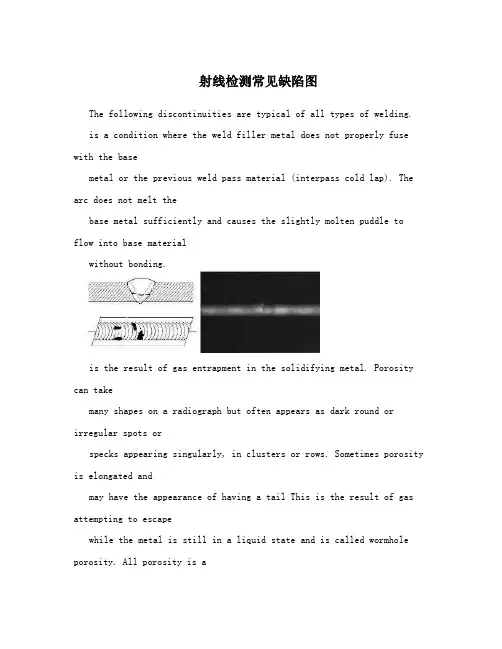
射线检测常见缺陷图The following discontinuities are typical of all types of welding.is a condition where the weld filler metal does not properly fuse with the basemetal or the previous weld pass material (interpass cold lap). The arc does not melt thebase metal sufficiently and causes the slightly molten puddle to flow into base materialwithout bonding.is the result of gas entrapment in the solidifying metal. Porosity can takemany shapes on a radiograph but often appears as dark round or irregular spots orspecks appearing singularly, in clusters or rows. Sometimes porosity is elongated andmay have the appearance of having a tail This is the result of gas attempting to escapewhile the metal is still in a liquid state and is called wormhole porosity. All porosity is avoid in the material it will have a radiographic density more than the surrounding area.(密集气孔)is caused when flux coated electrodes are contaminated with moisture. The moisture turns into gases when heated and becomes trapped in theweld during the welding process. Cluster porosity appear just like regular porosity in theradiograph but the indications will be grouped close together.are nonmetallic solid material entrapped in weld metal or between weld and base metal. In a radiograph, dark, jagged asymmetrical shapes within the weldor along the weld joint areas are indicative of slag inclusions.occurs when the weldmetal fails to penetrate the joint. It is one of the most objectionable weld discontinuities.Lack of penetration allows a natural stress riser from which a crack may propagate. Theappearance on a radiograph is a dark area with well-defined,straight edges that followsthe land or root face down the center of the weldment.(未融合)is a condition where the weld filler metal does not properly fuse with the base metal. Appearance on radiograph: usually appears as a dark line orlines oriented in the direction of the weld seam along the weld preparation or joiningarea.is condition where the weld metal has contracted as it cools and has been drawn up into the root of the weld. On a radiograph it lookssimilar to lack of penetration but the line has irregular edges and it is often quite wide inthe center of the weld image.is an erosion of the base metal next to the root of the weld. In the radiographic image it appears as a dark irregular line offset from the centerline of the weldment. Undercutting is not as straight edged as LOP because itdoes not follow a ground edge.is an erosion of the base metal next to the crownof the weld. In the radiograph, it appears as a dark irregular line along the outside edgeof the weld area.are terms associated with a condition where two pieces being welded together are not properly aligned. The radiographic image is a noticeabledifference in density between the two pieces. The difference in density is caused by thedifference in material thickness. The dark, straight line is caused by failure of the weldmetal to fuse with the land area.is an area of a weld where the thickness of weld metal deposited is less than the thickness of the base material. It is very easy to determine by radiograph if the weld has inadequate reinforcement, because the imagedensity in the area of suspected inadequacy will be more (darker) than the image densityof the surrounding base material.is an area of a weld that has weld metal added in excess of that specified by engineering drawings and codes. The appearance on a radiograph is a localized, lighter area in the weld. A visual inspection will easilydetermine if the weld reinforcement is in excess of that specified by the engineeringrequirements.can be detected in a radiograph only when they are propagating in a direction that produces a change in thickness that is parallel to the x-ray beam. Crackswill appear as jagged and often very faint irregular lines. Cracks can sometimes appearas "tails" on inclusions or porosity.The following discontinuities are peculiar to the TIG welding process. Thesediscontinuities occur in most metals welded by the process including aluminum andstainless steels. The TIG method of welding produces a clean homogeneous weld whichwhen radiographed is easily interpreted.Tungsten is a brittle and inherently dense material used inthe electrode in tungsten inert gas welding. If improper welding procedures are used,tungsten may be entrapped in the weld. Radiographically, tungsten is more dense thanaluminum or steel; therefore, it shows as a lighter area with a distinct outline on theradiograph.are usually visible on the surface of material being welded (especially aluminum). Oxide inclusions are less dense than the surrounding materials and,therefore, appear as dark irregularly shaped discontinuities in the radiograph.The following discontinuities are most commonly found in GMAW welds.are short lengths of weld electrode wire, visible on the top or bottom surface of the weld or contained within the weld. On a radiograph they appear as light, "wire like"indications.results when too much heat causes excessive weld metal topenetrate the weld zone. Often lumps of metal sag through the weld creating a thickglobular condition on the back of the weld. These globs of metal are referred to as icicles.On a radiograph, burn through appears as dark spots, which are often surrounded bylight globular areas (icicles).Radiograph Interpretation – CastingsThe major objective of radiographic testing of castings is the disclosure of defects that adversely affect the strength of the product. Casting are a product form that often receive radiographic inspection since many of the defects produced by the casting process are volumetric in nature and, thus, relatively easy to detect with this method. These discontinuities of course, are related to casting process deficiencies, which, if properly understood, can lead to accurate accept-rejectdecisions as well as to suitable corrective measures. Since different types and sizes of defects have different effects of the performance of the casting, it is important that the radiographer is able to identify the type and size of the defects. ASTM E155, Standard for Radiographs of castings has been produced to help the radiographer make a better assessment of the defects found components. The castings used to produce the standard radiographs have been destructively analyzed to confirm the size and type of discontinuities present. The following is a brief description of the most common discontinuity types included in existing reference radiograph documents (in graded types or as single illustrations).Gas porosity or blow holes are caused by accumulated gas or airwhich is trapped by the metal. These discontinuities are usually smooth-walled rounded cavities of a spherical, elongated or flattened shape. If thesprue is not high enough to provide the necessary heat transfer needed to force the gas or air out of the mold,the gas or air will be trapped as the molten metal begins to solidify. Blows can also be caused by sand that istoo fine, too wet, or by sand that has a low permeability so thatgas can't escape. Too high a moisture content inthe sand makes it difficult to carry the excessive volumes of water vapor away from the casting. Another causeof blows can be attributed to using green ladles, rusty or damp chills andchaplets.Sand inclusions and dross are nonmetallic oxides, appearing on the radiograph as irregular, dark blotches. These come from disintegrated portions of mold or core walls and/or from oxides (formed in the melt) whichhave not been skimmed off prior to introduction of the metal into the mold gates. Careful control of the melt,proper holding time in the ladle and skimming of the melt during pouring will minimize or obviate this sourceof trouble.Shrinkage is a form of discontinuity that appears as dark spots on the radiograph. Shrinkage assumes variousforms but in all cases it occurs because molten metal shrinks as it solidifies, in all portions of the final casting.Shrinkage is avoided by making sure that the volume of the casting is adequately fed by risers whichsacrificially retain the shrinkage. Shrinkage can be recognized in a number of characteristic by varyingappearances on radiographs. There are at least four types: (1) cavity; (2) dendritic; (3) filamentary; and (4)sponge types. Some documents designate these types by numbers, without actual names, to avoid possiblemisunderstanding.Cavity shrinkage appears as areas with distinct jagged boundaries. It may be produced when metal solidifiesbetween two original streams of melt, coming from oppositedirections to join a common front; cavityshrinkage usually occurs at a time when the melt has almost reached solidification temperature and there is nosource of supplementary liquid to feed possible cavities.is a distribution of very fine lines or small elongated cavitiesthat may vary in density and are usually unconnected.usually occurs as a continuous structure of connected lines or branches of variable length, width and density, or occasionally as a network.shows itself as areas of lacy texture with diffuse outlines, generally toward the mid-thickness of heavier casting sections. Sponge shrinkage may bedendritic or filamentary shrinkage; filamentary sponge shrinkage appears more blurredbecause it is projected through the relatively thick coating between the discontinuitiesand the film surface.are thin (straight or jagged) linearly disposed discontinuities that occur after the melt has solidified. They generally appear singly and originate at casting surfaces.generally appear on or near a surface of cast metal as a result of two streams of liquid meeting and failing to unite. They may appear on a radiograph as cracks orseams with smooth or rounded edges.Inclusions are nonmetallic materials in a supposedly solid metallic matrix. They may be less or more dense than the matrix alloy and willappear on the radiograph, respectively, as darker or lighter indications. The lattertype is more common in light metal castings.shows itself as a variation in section thickness, usually on radiographic viewsrepresenting diametrically opposite portions of cylindrical casting portions.are linearly disposed indications that represent fractures formed in a metalduring solidification because of hindered contraction. The latter may occur due to overlyhard (completely unyielding) mold or core walls. The effect of hot tears, as a stressconcentration, is similar to that of an ordinary crack; how tearsare usually systematicflaws. If flaws are identified as hot tears in larger runs of a casting type, they may call for explicit improvements in technique.appear on the radiograph as prominent dense areas of variable dimensions witha definite smooth outline. They are mostly random in occurrence and not readily eliminated by specific remedial actions in the process.is a radiographic indication that appears as an indistinct area of more or lessdense images. The condition is a diffraction effect that occurs on relatively vague, thin-section radiographs, most often with austenitic stainless steel. Mottling is caused by interaction of the object's grain boundary material with low-energy X-rays (300 kV or lower). Inexperienced interpreters may incorrectly consider mottling as indications of unacceptable casting flaws. Even experienced interpreters often have to check the condition by re-radiography from slightly different source-film angles. Shifts in mottling are then very pronounced, while true casting discontinuities change only slightly in appearance.Most common alloy castings require welding either in upgrading from defective conditions or in joining to other system parts. It is mainlyfor reasons of casting repair that these descriptions of the more common weld defects are provided here. The terms appear as indication types in ASTM E390. For additional information, see theNondestructive Testing Handbook, Volume 3, Section 9 on the "Radiographic Control ofWelds."is nonmetallic solid material entrapped in weld metal or betweenweld material andbase metal. Radiographically, slag may appear in various shapes,from long narrowindications to short wide indications, and in various densities,from gray to very dark.is a series of rounded gas pockets or voids in the weld metal, andis generally cylindrical or elliptical in shape.is a groove melted in the base metal at the edge of a weld and left unfilled by weld metal. It represents a stress concentration that often must be corrected, andappears as a dark indication at the toe of a weld., as the name implies, is a lack of weld penetration through thethickness of the joint (or penetration which is less than specified). It is located at thecenter of a weld and is a wide, linear indication.is lack of complete fusion of some portions of the metal in a weld jointwith adjacent metal; either base or previously deposited weld metal. On a radiograph,this appears as a long, sharp linear indication, occurring at the centerline of the weld jointor at the fusion line.is a convex or concave irregularity (on the surface of backing ring, strip, fused root or adjacent base metal) resulting from complete melting of a localized regionbut without development of a void or open hole. On a radiograph, melt-through generallyappears as a round or elliptical indication.is a void or open hole into a backing ring, strip, fused root or adjacent base metal.is an indication from a localized heat-affected zone or a change in surface contour of a finished weld or adjacent base metal. Arc strikes are caused by the heatgenerated when electrical energy passes between surfaces of the finished weld or basemetal and the current source.occurs in arc or gas welding as metal particles which are expelled during welding and which do not form part of the actual weld: weld spatter appears as manysmall, light cylindrical indications on a radiograph.is usually denser than base-metal particles. Tungsten inclusions appear most linear, very light radiographic images; accept/reject decisions for this defectare generally based on the slag criteria.is the condition of a surface which is heated during welding, resulting in oxide formation on the surface, due to partial or complete lack of purge of the weld atmosphere.Also called sugaring.shows the penetration of weld metal into the backing ring or into theclearance between backing ring or strip and thebase metal. It appears in radiographs as asharply defined film density transition.appears as an intermittent or continuous groove in the internal surface of thebase metal, backing ring or strip along the edge of the weld root.Real-time RadiographyReal-time radiography (RTR), or real-time radioscopy, is a nondestructive test (NDT)method whereby an image is produced electronically rather than on film so that very littlelag time occurs between the item being exposed to radiation and the resulting image. Inmost instances, the electronic image that is viewed, results from the radiation passingthrough the object being inspected and interacting with a screen of material thatfluoresces or gives off light when the interaction occurs. The fluorescent elements of thescreen form the image much as the grains of silver form the image in film radiography.The image formed is a "positive image" since brighter areas on the image indicate wherehigher levels of transmitted radiation reached the screen. This image is the opposite ofthe negative image produced in film radiography. In other words, with RTR, the lighter,brighter areas represent thinner sections or less dense sections of the test object.Real-time radiography is a well-established method of NDT having applications in automotive, aerospace, pressure vessel, electronic, andmunition industries, among others. The use of RTR is increasing due to a reduction in the cost of the equipment and resolution of issues such as the protecting and storing digital images. Since RTR is being used increasingly more, these educational materials were developed by the North Central Collaboration for NDT Education (NCCE) to introduce RTR to NDT technician students.。
射线检测典型缺陷
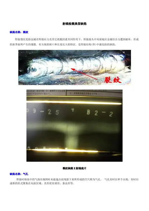
缺陷名称:裂纹
焊接裂纹是指金属在焊接应力及其它致脆因素共同作用下,焊接接头中局部地区金属结合力遭到破坏,形成的新界面所产生的缝隙, 有尖锐的缺口和长宽比大的特征, 是焊接结构(件)中最危险的缺陷。
裂纹缺陷X射线底片
缺陷名称:气孔
焊接时熔池中的气泡在凝固时未能逸出而残留下来所形成的空穴称为气孔。
气孔有时以单个出现,有时以成堆的形式聚集在局部区域,其形状有球形、条虫形等。
密集气孔缺陷X射线底片
缺陷名称:夹渣
焊后残留在焊缝中的熔渣称为夹渣,形状较复杂,一般有线状、长条状、颗粒状等。
主要发生在坡口边缘和
每层焊道之间非圆滑过渡的部位,焊道形状发生突变或存在深沟的部位也容易产生夹渣。
条状夹渣缺陷X射线底片
缺陷种类:未熔合
在焊缝金属和母材之间或焊道金属与焊道金属之间末完全熔化结合的部分称为未熔合,常出现在坡口的侧壁、多层焊的层间及焊缝的根部。
这种缺陷有的间隙很大,与熔渣难以区别,未熔合区末端易产生微裂纹。
未熔合缺陷X射线底片
缺陷种类:未焊透
焊接时,母材金属之间应该熔合而末焊上的部分称为末焊透。
出现在单面焊的坡口根部及双面焊的坡口钝边处。
末焊透易造成较大的应力集中,往往从端部产生裂纹。
未焊透缺陷X射线底片中心指示器未收起造成的底片错误曝光,如下图所示。

本文源自:中国无损检测论坛weld-01 (High - Low、高-低)也叫错边welld-02 (Incomplete Root Fusion、根部未熔合)welld-03 (Insuffucient Reinforcement、内凹)welld-04 (Excess Root Penetration、根部焊瘤)(External Undercut、外部咬肉)welld-06(Internal Undercut、内部咬肉)welld-07(Root Concavity、根部凹陷) (Root Concavity、根部凹陷)welld-08(Burn Through、烧穿) (Burn Through、烧穿)welld-09(Isolated Slag Inclusion、单个的夹渣) (Isolated Slag Inclusion、单个的夹渣)Wagon Track - Slag Line、线状夹渣线状夹渣(Interrun Fusion、内部未熔合) (Interrun Fusion、内部未熔合)welld-12(Lack of Sidewall Fusion、内侧未熔合) (Lack of Sidewall Fusion、内侧未熔合)welld-13(Porosity、气孔) (Porosity、气孔)(Cluster Porosity、链状气孔) (Cluster Porosity、链状气孔)welld-15(Hollow Bead、夹珠) (Hollow Bead、夹珠)welld-16(Transverse Crack、横向裂纹) (Transverse Crack、横向裂纹)(Centerline Crack、中心线裂纹) (Centerline Crack、中心线裂纹)welld-18(Root Crack、根部裂纹) (Root Crack、根部裂纹)(Tungsten Inclusion)夹钨(Tungsten Inclusion)夹钨。