浪涌保护器说明书
- 格式:pdf
- 大小:1.72 MB
- 文档页数:29
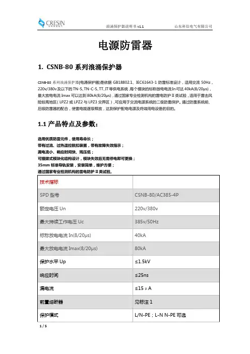
CDYN系列电涌保护器CDYNSCB系列电涌保护器专用保护装置产品样本北京办事处北区中区地址:北京市丰台区枫竹苑一区(未来假日花园)18-10 邮编:100076天津办公点地址:天津市西青区凯安道凯信佳园9-3-401邮编:300100沈阳办公点地址:辽宁省沈阳市于洪区细河南路碧桂园银河城钻石郡148-3邮编:110000长沙办公点地址:湖南长沙市芙蓉区万象企业公馆5栋2709邮编:410000郑州办公点地址:河南郑州金水区青年路145号6号楼17层1706号邮编:450000武汉办公点地址:湖北武汉市江汉区新华路186号福星国际商会大厦2516、2517室邮编:430000温州办公点地址:浙江省乐清市柳市镇德力西工业园邮编:325604成都办公点地址:成都市金牛区人民北路二段118号金牛万达广场甲级C座 16楼1603号邮编:610000南京办公点地址:江苏省南京市秦淮区洪武路23号隆盛大厦1505、1506室邮编:210000重庆办公点地址:重庆市九龙坡区渝洲路4号18-9号邮编:400039广州办事处地址:广州市荔湾区南岸路63号城启大厦1905室 邮编:510160南宁办公点地址:南宁市西乡塘区北大路中梦泽园小区岳阳阁5单元202室邮编:530003昆明办公点地址:昆明市西山区棕树营街道办事处土堆村碧鸡名城C地块9幢2802室邮编:650000贵阳办公点地址:贵阳市观山湖区石林东路中天帝景传说B区B4栋1单元1302室西安办事处地址:陕西西安市莲湖区大庆路三号蔚蓝国际A705 邮编:710082新疆办公点地址:新疆乌鲁木齐市米东区米东南路红光雅居D区6号楼3单元602室邮编:830000青岛办公点地址:青岛市城阳区正阳路177号15号楼2单元903室邮编:214000福建办公点地址:福州市晋安区东二环泰禾广场7号楼1117单元邮编:350024济南办公点地址:山东省济南市历下区工业南路55号未来城商务中心13#楼608室邮编:250000杭州办公点地址:杭州市江干区蓝桥景苑11幢2单元1002室邮编:310016南昌办公点地址:江西南昌市西湖区广场东路恒茂国际华城23幢2907邮编:330002深圳办公点地址:深圳市龙华新区民丰路1号碧水龙庭7栋4单元14D 邮编:518109兰州办公点地址:兰州市城关区瑞德摩尔万国港E座2208邮编:730020电话:153****1522合肥办公点地址:安徽省合肥市瑶海区武里山路五里山天街3A-1402室邮编:230000吉林办公点地址:吉林省长春市经开区浦东路与深圳街交汇处虹湾国际A座706室邮编:130031黑龙江办公点地址:黑龙江省哈尔滨市道外区润达国际D座2单807室邮编:150050石家庄办公点地址:石家庄市裕华区华兴生活小区41-1-102邮编:050011太原办公点地址:山西太原市万柏林区西矿街70号红星小区五单元1402邮编:030024石家庄物流地址:河北省石家庄市元氏县殷村石武铁路东国达物流园内电话:155****1257辽宁物流地址:沈阳市苏家屯区雪莲街188号(雪莲街与四环路交叉口)华翔东北亚贸城 D1 德力西陕西物流地址:陕西省西安市六村堡丰产路西段陕西商储物流园南区B1号德力西仓库山东物流地址:山东省临沂市经济技术开发区翔宇路23号华派克物流园内 重庆物流地址:重庆市江津区珞璜工业园B区重庆西部诚通物流有限公司5号库成都物流地址:四川省成都市青白江区国际集装箱物流园区德汇路9号4栋4-4号广东物流地址:广东省佛山市南海区里水镇怡和二路银裕木业制品厂直入100米河南物流地址:河南省郑州市经济开发区国际物流园喜达路宇培物流园(礼通路)东北W4-A区4B 58-59号湖北物流地址:湖北省武汉市东西湖区临空港大道23号捷利物流园3号库温州物流地址:浙江省乐清市柳市镇德力西高科技生态工业园新疆物流地址:乌鲁木齐市友谊路230号(新疆诚通国际物流园内德力西仓库)芜湖物流地址:安徽省芜湖市芜湖县新芜经济开发区朝阳路德力西物流中心产品介绍电涌保护器基础知识产品介绍技术参数SPD 常用名词解释怎样看电涌保护器的好坏?它有些什么主要技术参数,各有什么重要性?为什么电涌保护器需要后备保护装置?电涌保护器的后备保护装置需要满足那些要求?不同接地系统SPD 极数的选择Ⅰ类实验 (Class I test)用标称放电电流In 、1.2/50冲击电压和最大冲击电流Iimp 做的试验。
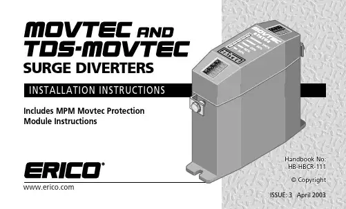
INSIDE FRONT COVER(Blank)CONTENTSPage1. Warnings ... ... ... ... ... ... ... ... ... ... (4)2. Introduction ... ... ... ... ... ... ... ... ... (5)3. Protection Concepts.. ... ... ... ... ... ... (7)4. Mounting and Cautions... ... ... ... ... (9)5. Voltage Ratings.. ... ... ... ... ... ... ... (10)6. Protection Mode.. ... ... ... ... ... ... ... (13)7. Connection Method ... ... ... ... ... ... (15)8. RCD, ELCB... ... ... ... ... ... ... ... ... (20)Page9. Isolation and Fusing... ... ... ... ... ... (20)10. Status Indication and Alarms... ... (22)11. MPM, Movtec Protection Module ... (24)12. Maintenance and Testing.. ... ... ... (27)13. Extended Warranty... ... ... ... ... ... (28)14. Six Point Plan... ... ... ... ... ... ... (29)15. Use of Mimic Panels... ... ... ... ... (30)1. WARNINGS•Prior to installation ensure that the Movtec is of the correct voltage andfrequency, and is the type recommended for the local power distribution, and for theequipment being protected.•Hazardous voltages may exist internally to the units. The units should be installed(and replaced) only by qualified personnel in accordance with all relevant Electricity Safety Standards.•Do not power MPMs and three phase connected Movtecs (Ph-N) without theupstream neutral connected. Failure to do so may damage the Movtecs and/or theload.•Where the MPMs/Movtecs are connected to an earth, this must be a low impedance earth (<10 Ω) for correct operation.•X1-X4 connections may be at phase voltages dependant upon connection method.•If connecting to the Movtec alarm outputs do not exceed the maximum permissibleratings as damage may occur.•Movtecs must be installed in anenclosure or panel, ensure this does notcause their environmental ratings to beexceeded.•Do not “Megger” or “Flash Test” circuits with Movtecs installed.•The DINLINE Surge Counter (DSC) should not be used in voltage sensing mode withTDS-Movtecs. Voltage sensing mode is not compatible with TDS-Movtecs.•All instructions must be followed to ensure correct and safe operation.•Diagrams are illustrative only, and should not be relied on in isolation.2. INTRODUCTIONMovtecs are designed to protect mains powered equipment from the damaging effects of lightning and transients. They are ideal for point-of-entry shunt protection applications where robustness and high surge ratings are required.The Movtec family is designed to suit many distribution systems including TN-C, TN-S, TN-C-S and TT. They can be selected for use with distribution systems with nominal voltages of 110/120V, 220/240V and 277Vrms at frequencies of 50/60 Hz.The TDS Technology (Transient Discriminating Suppressor) units are specifically designed for distribution systems that may feature poor voltage regulation where the actual supply voltage may exceed the nominal ratings for extended periods.This Installation Manual details the preferred procedure for the installation of the family of Critec Movtec™ Surge Diverters.The Critec Movtec family includes:•Critec Movtec, Single Mode, enhanced MOV technology units eg. (MT275V-135K-A)•Critec TDS-Movtec, Single Mode, TDS technology unit featuring high over-voltage withstand for added robustness (TDS-MT-277)•Critec TDS-Movtec, Three Mode, TDS technology unit featuring high over-voltage withstand for added robustness (TDS-MTU) TDS-Movtec units are coloured blue for easy identification, while enhanced MOV technology units are coloured red.In this manual, reference to “ Movtec” also includes “TDS-Movtec”.4. MOUNTING & CAUTIONSThe performance of surge diverters can be dramatically affected by the method of connection (refer section 7). Where possible select a mounting method that allows the Movtec to be connected in the “Preferred Connection Method”.Failure of a Movtec under severe AC over-voltage, such as 11kV on 240V mains, can result in the generation of significant heat. Consideration should be given to ensure that Movtecs are not installed in close proximity to combustible materials.Units must be installed in an enclosure or panel to provide the appropriate degree of electrical and environmental protection.Only use enclosures that:•Do not cause the Movtec temperature to exceed 60 deg C•Provide adequate electrical and safety protection•Prevent the ingress of moisture and water •Allow Movtec Status Indication to be inspected5 VOLTAGE RATINGSThe TDS (Transient Discriminating Suppressor) technology has been specifically developed to cater for abnormal over-voltage conditions that may occur on sites with poor voltage regulation, or due to wiring or distribution faults. The TDS units feature an extremely high over-voltage withstand to eliminate heat build up that can occur with standard technologies when the protection devices start to clamp on the peak of each abnormal mains cycle.Traditional MOV technology (eg MT-275V/ 135K/A) is not suitable in applications where sustained over-voltage conditions can be experienced.Examples of poorly regulated voltage environments include:•Smaller power generation supplies•Sites with large earth currents•Variable motor speed control circuits •High harmonic voltage environments (non-linear loads)The TDS range of Movtecs with a higher over-voltage withstand may be able to be used in these environments following advice.Transient protection devices are usually rated to protect against non-repetitive pulses from such sources as direct or induced lightning strikes. They are not designed to provide protection against repeated cyclic anomalies. Nor are they designed to provide protectionagainst sustained over-voltage conditions where the supply voltage exceeds the protection equipment’s nominal rating for an extended period of time, ie continuous over-voltages from poorly regulated generators or distribution systems.Smaller power generation equipment (particularly capacitive excitation induction generators) does not generally conform to the same standards of voltage regulation that are in place for mains power reticulation. A large number of smaller and/or cheaper generators have a voltage waveform that is “loosely”240Vrms (often poorly regulated), but more importantly, often contains significant higher order harmonics. These generators may exhibit a peak voltage on each half cycle far in excess of the normal 340V. The problem is usually worse when the generator is lightly loaded.Whilst electrical equipment may tolerate this over-voltage for a period of time, the clamping elements in the power protection devices will begin to conduct on the peak of each 50Hz cycle, as their voltage threshold is reached (typically 400V peak for a traditional 275V diverter). This will cause slow degradation and ultimate failure of the clamping device (time dependent upon how poor the waveform is).Harmonic voltages may also be present in distribution systems that do not feature generators. This is normally where non-linear loads are used, such as UPSs, rectifiers, switch mode power supplies and motor speed controls. The high harmonic voltages in certain applications may have peak voltages in excess of the protective clamping voltage causing problems as described above. Seek the manufacturer’s advice before installing anyproduct into a circuit which features a total harmonic voltage ratio above 5%.Ensure that the correct voltage rating unit is installed. Exceeding the nominal rating while transient events occur may affect product life.†Note: Other voltage rating Movtecs are available. Refer to Movtec table for actual ratings.6. PROTECTION MODESMovtecs are available in Three Mode and Single Mode configurations. This refers to how the internal protection is arranged and applied to the circuit to be protected.Three Mode units provide protection between the Phase-Neutral*, Phase-Earth* and Neutral-Earth circuit within one Movtec. Single Mode units provide protection between two conductors connected to the terminals marked T1 and T2. These units can be connected to provide protection from Phase-Neutral* or Phase-Earth* or Neutral-Earth. To allow the status indication and alarm circuitry to operate, a neutral connection is required for Phase-Earth* configured units, and a Phase* connection is required for*Note. Some users may be used to the terminology “Active” or “Line”, in place of“Phase”. For consistency “Phase” is usedthroughout this documentation.7. CONNECTION METHOD Array To optimise transient performance, attempt to connect the Movtecs in the “Preferred” fashion as depicted on pages 16 and 17. This is recommended for cable sizes between 6mm2 and 16mm2. Take care not to run the protected and unprotected wire parallel or in close proximity.Where this is not possible due to layout or conductor size, use the “Non-preferred” “T”connection method as depicted on pages 16 to 18. With this connection method, the “T” lead should be between 6mm2 and 16mm2. The connection should be as short as practicable (less than 100mm).Cable sizes less than 6mm2 should not be usedwithout specialist advice.8. RCD, ELCBWhere RCDs/ELCBs (Residual Current Devices / Earth Leakage Circuit Breakers) are fitted the Movtecs should be installed in the circuit prior to these devices (ie upstream). Where this can not be avoided and RCDs/ ELCBs are installed upstream, nuisance tripping of the RCD/ELCB may occur during transient activity.Contact your local ERICO agent for advice if upstream RCDs/ELCBs can not be avoided. 9. ISOLATION AND FUSING Overcurrent and short circuit protection must be provided to protect the Movtec and associated wiring if a fault develops. The overcurrent protection should be installed in such a manner to also provide a means of isolating the Movtec module from the mains supply. This is an important safety consideration and is required in the event that any future maintenance or testing is needed. The Movtec uses disconnection devices to isolate internal segments that have reached the end of their service life. In order for this disconnection to occur correctly, Movtecs should be only used on circuits with fuse or circuit breaker ratings of 32A or greater. (Nuisance operation of the overcurrent protection may occur during transient activity on smaller capacity circuits.)On circuits with a capacity of greater than 100A, the Movtecs should be installed in series with a 100A HRC fuse being placed prior to the Movtec, as detailed in the diagram on page 21. This will require the Movtec to be installed in a similar manner to the non-preferred “T” connection method. Care must be taken to keep “T” connections as short and straight as possible. Note that this fuse may rupture under surge events exceeding 60kA, thereby disconnecting the protection circuit. Under such conditions it is important that suitable monitoring of the alarm contact should be carried out to detect this possible occurrence.10. STATUS INDICATION AND ALARMSA characteristic of all transient and surge protection devices is that they degrade in proportion to the magnitude and number of incident surges to which they have been subjected. Status indication should be periodically monitored to determine if replacement is required.Each Movtec features 5 protection segments. The status for each of these sectors is provided by way of a 5 segment LED bar graph. If any sector is damaged due to excess surge activity, a LED will extinguish. The LEDs extinguish in a sequential order (100% LED out first, 80% LED out next etc.) irrespective of which sector has sustained damage.of one of the three modes and that the TDS-Movtec unit should be replaced.Where multiple Movtecs are used, such as in three phase distribution systems the alarm contacts may simply be connected in series to provide a common alarm output connection.When mains voltage is applied to the fully functional Movtec, the alarm contacts will be closed . Should the surge handling capacity fall to below the alarm threshold, thesecontacts will open . The contacts are “fail-safe”in that, if power to the unit fails, the contacts will also revert to the open condition.For Single Mode units (TDS-MT-277 and MT275V-135K-A)•The voltage free alarm contacts are activated (opened) as soon as the primary protection status displays 60% or less and indicates that the Movtec unit should be replaced.For Three Mode units (TDS-MTU)•The voltage-free alarm contacts are activated (opened) as soon as the protection status displays 80% or less. This indicates thatdamage has been sustained to the protection11. MPM, MOVTEC PROTECTION MODULEThe MPM utilises a high energy Neutral to Earth spark gap to provide robust protection against earth potential rise problems. Care is required to ensure co-ordination of this device if any other voltage limiting device is connected either upstream or downstream in the Neutral to Earth circuit. Contact your local agent for further information if other N-E protection devices are installed and co-ordination may be affected.INSTALLATION PROCEDURE FOR MPM1.Remove the cover from the MPM.2.Select the MPM mounting position to ensureoptimum electrical connection method (refer Section 7) and in accordance with all giveninstructions.3.Position and mark the mounting position ofthe MPM on the wall.4.Depending on the mounting surface, preparesuitable anchoring holes for the markedposition.5.Snap the mounting spacers, supplied, intothe rear of the back of the MPM as shownin Figure 1. (see inside back cover P31)6.Mount the unit to the wall. To ensure theIP33 rating is preserved, the MPM shouldbe mounted to the wall using the spacersprovided and one of the fixing methods asshown in Figure 1. (see inside back cover P31)7.Prepare the appropriate cable glands. It isrecommended that a nylon cable gland(typically rated at IP66) be used.8.Install wiring, taking care to support cablingdirectly connecting to the MPM unit, andtighten all terminals.9.Check that the MPM is installed in accord-ance with all instructions, and relevantelectrical safety codes.10.Replace MPM cover, then apply power.11.Correct operation of the MPM unit is estab-lished by checking that all 5 LED’s on each MOVTEC bar graph are lit, and that power is correctly being supplied to the load(s). INSTALLATION ARRANGEMENT FOR AUSTRALIAN MEN SYSTEMSUnder Australian Standards classification, MPMs are considered a piece of equipment tobe connected to the mains Array supply. The MPMs are not intended for use as, nor are they, a ‘switch board’,‘distribution board’ or other equipment. As MPMs are classified as ‘electrical equipment’ (ie: a product), AS 3000 Wiring Regulations apply to the installation and operation of the units.In the multiple earth neutral (MEN) distribution system, the MPM equipment should be installed as close as possible after the MEN point and after both the main disconnect switch/ overcurrent protector andany metering equipment.12. MAINTENANCE & TESTING Before removing any unit from service ensure that power to the device is isolated. Replacement of any Movtecunits should only be undertaken in accordance with all relevant Electricity and Safety Standards by suitablyqualified personnel.Movtecs should be inspected periodically, and also following any periods of lightning or transient activity. Check the status indicators and replace if in the “Alarm” condition as detailed in Section 10 -STATUS INDICATION. For high transient exposure sites or those of a critical operational nature, it is recommended that the alarm outputs be monitored to provide an additional warning of reduced capacity (refer Section 10).Movtecs are designed for optimum performance under severe transient activity. To provide this performance, electronic components in the Movtec are encased in a patented proprietary, shock and thermal absorbant compound. Units cannot be serviced, they must be replaced.Do not attempt to open or tamper with the units in any way as this may compromise performance and will void warranty.Do not “Megger” or perform other types of electrical tests that apply voltages greater than the nominal operating voltage of the Movtec. The Movtec will attempt to limit these voltages thereby affecting the test result. Where these tests must be performed, remove the Movtec from circuit first.13. EXTENDED WARRANTYThis product has a limited warranty to be free from defects in materials and workmanship for a period of five (5) years from the date of dispatch from the Manufacturer. The Purchaser acknowledges that lightning is a natural event with statistical variation in behaviour and energy levels which may exceed product ratings, and 100 % protection is not offered and cannot be provided for. Therefore the Manufacturer’s liability is limited to the repair or replacement of the product (at the Manufacturer’s sole option) which in its judgement has not been abused, misused, interfered with by any person not authorised by the Manufacturer, or exposed to energy or transient levels exceeding the Manufacturer’s specifications for the product. The product must be installed and earthed (where applicable) in strict accordance with the Manufacturer’s specifications and all relevant national Electricity and Safety Standards. The Manufacturer and the Purchaser mutually acknowledge that the product, by its nature, may be subject to degradation as a consequence of the number and severity of surges and transients that it experiences in normal use, and that this warranty excludes such gradual or sudden degradation. This warranty does not indemnify the Purchaser of the product for any consequential claim for damages or loss of operations or service or profits. Customers should contact their nearest manufacturer’s agent to obtain a Product Repair Authorisation Number prior to making any claim under this warranty. This is only a summary of the warranty given by the Manufacturer. The full text of the warranty is set out in the Manufacturer’s Conditions of Quotation and Sale. The above limited warranty is additional to rights which arise in respect of the sale of industrial and technical products and services to knowledgable buyers under the Australian Trade Practices Act 1974 as amended.loops anddifferentialsProtect equipmentthrough a lowimpedance earthsystem15. USE OF MIMIC PANELSMovtecs are used in the Proline range of Surge Reduction Filters where superiorprotection is required for critical or sensitive electronic equipment. Some models of SRF use an electronic mimic panel to display in thefront door the status of the internal Movtecs.The X1-X4 terminals on the Movtec are used for this purpose. If this Movtec is to be used with a mimic panel (possibly as a replacement for an existing Movtec in a SRF) please ensure compatibility as below.Figure 1. MPM mounting spacers.。

浪涌保护器的使用方法嘿,朋友们!今天咱来聊聊浪涌保护器这玩意儿的使用方法。
这东西啊,就像是家里电器的小保镖!你想啊,电就像个调皮的小孩子,有时候会突然发脾气,来个大波动,这要是没个保护的,咱那些宝贝电器可不得遭殃啊!浪涌保护器就是专门来对付这种情况的。
那怎么用它呢?首先得选对地方安装。
就好比你给花找个合适的花盆一样,得放在能发挥它最大作用的地方。
一般来说,就在配电箱里给它安个家。
安装的时候可别马马虎虎的,得拧紧螺丝,让它稳稳当当的待在那。
然后呢,要定期检查检查它。
这就跟咱人得时不时去体检一样。
看看它有没有啥毛病,指示灯是不是正常亮着呀。
要是发现有啥不对劲,赶紧处理,可别拖着。
你说要是它坏了不工作了,那不就等于保镖失职了嘛,那咱的电器还不得提心吊胆的。
还有啊,可别以为装上浪涌保护器就万事大吉了。
咱平时用电也得注意点,别啥大功率电器都一股脑插上,那也容易出问题呀。
就像你让一个人干太多活,他也会累垮的呀。
而且啊,这浪涌保护器也不是能一直保护下去的,它也是有寿命的哟!就像咱的鞋子,穿久了总会磨损的嘛。
所以到了一定时候,就得给它换换啦。
你想想,要是一直穿着破了的鞋子走路,多不舒服呀,同理,一直用着过期的浪涌保护器,能让人放心吗?咱再打个比方,浪涌保护器就像是一道坚固的城墙,把那些乱七八糟的电涌都给挡在外面,保护着城里的电器们。
要是这城墙不牢固了,那还怎么保护呢?所以啊,大家可一定要重视它的使用和维护哦!总之,浪涌保护器虽然看着不起眼,但作用可大着呢!咱可不能小瞧了它。
好好对待它,让它好好为咱的电器服务,这样咱才能安心地享受各种电器带来的便利呀,对吧?大家可一定要记住这些使用方法哦,别不当回事儿!。

᱂ܝ⇨ϴЏԧᓔথഄ☦▊ṗᎹ࣏☿⇨☿⇨᪂᪂07/⌾⍠⌾⍠ֱᡸ఼ֱᡸ఼ֱᡸ఼ՓϬՓϬՓϬ᪸ᯢк᪸ᯢк᮴⏥᮴⏥ṙᗱᅝṙᗱᅝṙᗱᅝᅝܼᅝܼᅝܼ᪂᪂᪂᳝└᳝└᳝└݀ৌ݀ৌT h e S L P S e r i e s is a range of surge protec-tion devices combining high packing densi-ties, application versatility, proven hybrid cir-cuitry and simple installation -- features which make the series the most cost effec-tive surge protection solution for process control equipment systems and communica-tions networks.T h e m u l t i -s t a g e h y b r i d s u r g e p r o t e c t i o n n e t -w o r k at the heart of the SLP uses a combi-nation of solid state electronics and a gas filled discharge tube (GDT) to provide surge protection up to 20kA. This impressive surge protection circuit is designed to exhibit exceptionally low line resistance and adds only a tiny voltage drop to the circuit.I n o p e r a t i o n , t h e S L P d e v i c e d o e s n o t a d v e r s e l y a f f e c t t h e p e r f o r m a n c e o r o p e r a -t i o n o f t h e l o o p or combined equipment. The device allows signals to pass with very little attenuation while diverting surge currents safely to ground and clamping output volt-ages to safe levels.F u l l y a u t o m a t i c i n o p e r a t i o n ,SLP devicesreact immediately to make sure thatequipment is never exposed to damagingsurges between lines or the lines andground. Reacting instantaneously, the SLPredirects surges safely to ground andthen resets automatically.T h e v e r s a t i l e S L P s e r i e s d e s i g n c o n s i d e r st h e n e e d f o r h i g h p a c k i n g d e n s i t i e s andhas a product combining protection fortwo process loops into one case. Eachmodule provides full hybrid surge protec-tion for two process loops.F o r h i g h e r b a n d w i d t h a p p l i c a t i o n s ,the SLPseries has been developed to meet thedemands of today’s highest speed com-munication systems.O n e s i m p l e m a n u a l o p e r a -t i o n clamps modulessecurely onto D I Nrail, which auto-matically provides the essential high-integrity ground connection.A 10 Y e a r ‘N o F u s s ’ w a r r a n t y is available as standard for the SLP so if a correctly connected device should fail for any rea-son, simply return it for a free replace-ment.‘T o p -h a t ’ (T -s e c t i o n ) D I N r a i l is generally suitable for mounting SLP modules although for adverse environments, a spe-cially-plated version is available from MTL Surge Technologies.Data & SignalProtectionUltra-slim user-friendly devices for protecting electronic equipment and systems against surges on signal and I/O cabling.G S u r g e p r o t e c t i o n f o r t w o l o o p s p e r S L P (o r o n e 4-w i r e c i r c u i t )G P l u g c o n n e c t o r s f o r q u i c k a n d e a s y c o n n e c t i o n o r r e w i r i n gG S p a c e -s a v i n g d e s i g n , 6m m w i d t h p e r l o o pG M u l t i -s t a g e h y b r i d p r o t e c t i o n c i r c u i t r y - 20k A m a x i m u m s u r g e c u r r e n tG R a n g e o f v o l t a g e r a t i n g s - t o s u i t a l l p r o c e s s I /O a p p l i c a t i o n sG D e s i g n e d f o r h i g h b a n d w i d t h , l o w r e s i s t a n c e a p p l i c a t i o n sSLP SeriesS p e c i f i c a t i o n All figures typical at 77°F (25°C) unless otherwise statedM a x i m u m s u r g e c u r r e n t 20kA (8/20μs waveform) per line L e a k a g e C u r r e n t <1μA @ working voltage M a x i m u m r a t e d l o a d c u r r e n t1.50A L o o p r e s i s t a n c e 2 OhmC a p a c i t a n c eLine - Line - 60pFB a n d w i d t h-1db @9kHz - 37MHz-3dB @50MHzR e s p o n s e t i m e<1nsA m b i e n t t e m p e r a t u r e–40°F to +176°F (working)–40°C to +80°C (working)–40°F to +176°F (storage)–40°C to +80°C (storage)H u m i d i t y5 to 95% RH (non-condensing)T e r m i n a l s12 AWG (2.5mm 2)E l e c t r i c a l c o n n e c t i o n sPlug/header screw terminal strip M o u n t i n gT-section DIN-rail(35 x 15mm rail)W e i g h t5oz (140g approximately)Case flammabilityUL94 V-2E M C c o m p l i a n c eBS EN 60950:1992BS EN 61000-6-2:1999BS EN 61010-1:1993E l e c t r i c a l s a f e t yUL Isolated Loop Protector (Pending)Class I, Division 2, Groups A, B, C & Dhazardous locations (Pending)T o o r d e r s p e c i f y - Order by module, as listed in the specifi-cation table.Note: I n accordance with our policy of continuous improvement,we reserve the right to change the product’s specification withoutnotice.2 Installation Connection detailsR e vA09/16/04S t a n d a r d C e r t i f i c a t e /A p p r o v e d f o r P r。

SURGE PROTECTORSFORPhotovoltaic systemswww.citel.fr1221ROOF TOP INSTALLATIONSA professional approach to lightning and surge protection will guarantee your photovoltaic systems a long lifeSPD locationThe diagram below shows the pertinent locations for surge protectors as described in the CLC/TS61643-12 guide.Additional Surge ProtectorsIf the equipment to be protected (inverter or PV modules) is located more than 10 meters away from the initial surge protec-tor, the guide imposes the insertion of a complimentary surge protector to improve the level of protection.For low power PV applications, i.e. residences and small offices, it is necessary to consider surge protecting the AC output of the Inverter that connects directly into the electric power grid as well as the DC input side of the Inverter fed by the PV modules.AC Surge Protectorto protect all loads connected to the facility’s main distribution pa-nel against transients originating from the AC utility grid.AC networkAdditional AC Surge protectorIf the length of conductor between the PVinverter and the primary SPD in the main board exceeds 10 m, an additional SPD is necessary at the input of the inverter .Type 2 surge protectorDepending on the lightning rating of the installation area, a Type 2 surge protector on the DC network may be required.PV network AC network1222121121INDUSTRIAL AND PUBLIC BUILDINGSType 2 surge protectorIf the building is not equipped with a lightning rod system then a Type 2 surge protector is necessary or compulsory on the AC and DC inputs of the inverter . On the PV side, for cable lengths greater than 10 meters it is mandatory to install additional surge protectors at each end of the cable run.Type 1 surge protectorIf the installation is equipped with lightning rod systems, Type 1 surge protectors are compulsory at the AC input.The same on the DC side, Type 1 surge protectors are compul-sory in case of not isolated ligtning rod installation. Depending on the level of protection of the lightning rod, the total discharge current (Itotal) required can reach 20 kA.(See guide CLC / TS50539-12).Medium to large power PV systems can be installed on industrial and service facilities.In order to avoid very costly downtime and lost productivity resulting from a direct or indirect lightning strike, it is critical, and in some cases mandatory, to install surge protection at key points within your facility and its vital power and communication networks.AC networkType 2 AC surge protectorWhen the local lightning density is Ng > 2.5, by standard, it is mandatory to install an AC surge protector at the incoming service of the three phase network. In areas with a lower lightning density, while it is not mandatory, it is certainly good practice to install a surge protector for protection against switching transients originating from the external power grid not associated with lightning.Dataline Surge ProtectorsFor inverters connected to data networks(monitoring, control) or probes (luminous flux, temperature...), installation of relevant surge protectors is highly recommended.PV networkAC networkDatalinesAdditional AC Surge ProtectorDue to the long length of strings de-ployment, additional surge protectors are required near the PV modules. Installed generally in connection boxes.PV networkType 2 surge protectorDepending on the level of lightning strike in the installation area, a Type 2 SPD on the DC network at the in-verter input may be required. In the presence of non-isolated lightning rod, a Type 1 SPD is required.If the length of conductor between the PV inverter and the arrester in the MLVS ex-ceeds 10 m, an additional SPD is neces-sary at the input of the inverter.11111212PV POWER PLANTSType 1 surge protectorIf the PV field is equipped with lightning rod systems (rods, open air wiring…) Type 1 surge protectors are compulsory at the AC input.On the DC side, Type 1 surge protectors are compulsory at the inverters DC output as defined by CLC/TS 50539-12. Due to the long lengths of cabling required to connect numerous strings running throughout the PV farm, additional surge protectors are required at the input of the PV modules as well.PV power plants present a high risk of direct lightning impact and surges due to the large exposed area and the long lengths of the electric conductors.In order to avoid problems leading to costly damage and downtime, it is compulsory to install surge protectors at key points in the PV system.Type 1 DC Surge Protector panelDue to the long length of wires (>> 10 m), additional Type 1 SPDs are required at the input of PV modules. They are usually instal-led inside combiner boxes.AC Surge ProtectorType 1 surge protector is required at the AC network entrance whenever a light-ning rod is installed on the premises.Dataline Surge ProtectorsFor inverters connected to data networks (monitoring, control) or probes (luminous flux, temperature...), installation of relevant surge protectors is highly recommended.Type 1 DC Surge ProtectorDue to the risk of direct lightning strikes, Type 1 surge protector must be applied.AC network DatalinesPV networkPV networkDS60VGPV-1500G/51DS50PV-800G/51DLA-24D3DAC1-13-31-275 DAC40C-31-275DAC50-11-275 DAC40C-11-275DDC30C-20-65Head office FranceTél. : +33 1 41 23 50 23 e-mail:**************** Web : www.citel.fr FactoryReimsTél. : +33 3 26 85 74 00 e-mail:**************** Germany BochumTél. : +49 234 54 72 10 e-mail:************* Web : www.citel.deUSAMiramarTel : (954) 430 6310e-mail:*************Web site : ChinaSales departmentShanghaiTél. : +86 21 58 12 25 25e-mail:****************Web : FactoryTél. : +86 21 58 12 80 67RussiaMoscouTél. : +7 499 391 47 64e-mail:*************Web : www.citel.ruIndiaNew DelhiTél. : +91 11 2626 12 38e-mail:********************Web : www.citel.inThailandBangkokTél. : +66 (0) 2 104 9214Web : www.citel.frCITEL range DAC1-13DAC50DAC40C3-phaseDAC40C1-phase Surge protector Type 1+2Type 2Type 2Type 2AC network Un230 Vac230 Vac230 Vac230 Vac Max. AC operating voltage Uc255 Vac255 Vac255 Vac255 Vac Nom. discharge current (8/20µs)In20 kA20 kA20 kA20 kAMax. discharge current (8/20µs)Imax50 kA50 kA40 kA40 kAMax. lightning current (10/350µs)Iimp12.5 kA---Protection level Up 1.5/1.3 kV* 1.5/1.25 kV* 1.5/1.25 kV* 1.5/1.25 kV*P/N for single phase network DAC1-13-11-275DAC50-11-275-DAC40C-11-275 P/N for 3L+N network DAC1-13-31-275DAC50-31-275DAC40C-31-275-Télésignalisation de déconnexion OptionDAC1-13S-xx-xxxOptionDAC50S-xx-xxxOptionDAC40CS-xx-xxxOptionDAC40CS-xx-xxxDAC1-13 DAC50 DAC40C Type 1 and Type 2 Surge Protectors for AC power supply IEC61643-11 complianceDC SURGE PROTECTORS FOR PV OFF-GRID SITECITEL model DDC30C-20-65DDC40C-20-100DDC40C-20-180DDC40C-20-275DDC40C-20-460Network48 Vdc75 Vdc130 Vdc220 Vdc350 VdcMax.operating voltage Uc65 Vdc100 Vdc180 Vdc275 Vdc460 VdcNominal dischargecurrent (8/20µs)In15 kA20 kA20 kA20 kA20 kAProtection level Up300 V390 V620 V900 V1400 vRemote signalling OptionDDC30CS-20-65OptionDDC40CS-20-100OptionDDC40CS-20-180OptionDDC40CS-20-275OptionDDC40CS-20-460DDC30CDDC40C Type 2 Pluggable Surge Protector for PV Off-grid site- *) Common mode (L/PE or N/PE)/Differential mode (L/N)- Specific version DAC1-13VG and DAC50VG available: suppression of operating and leakage currents. SURGE PROTECTORS FOR AC NETWORK。
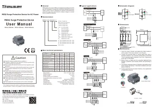
RES2 Surge Protective Device for AC PowerUser ManualRES2 Surge Protective DeviceThe company reserves the right to modify the product and changethe specification. If there is any update, it will be notified separately.RES2-20Series、RES2-40Series、RES2-80SeriesGeneral Typical applications Schematic diagramDimensionsMaintenanceNomenclatureMain technical parametersRES2 series AC power SPDs are designed according to the IECand GB standards. It enable the connection between the powersupply system and an equipotential network instantaneouslywhen the surge occurs and limits the residual voltage to a certainlevel to protect the devices.R E S2-X X-X X X X X-3none:F:w/o remote signalwith remote signalNumber of naught wireBlank means one naught wire2 means 2 naught wires3 means 3 naught wires1P:1G:2P:1PN1:3P:3PN1:4P:Single phase(MOV)Single phase(GDT)Single phase TNSingle Phase TT(with GDT)3phase 4wire, TN-C/IT3phase 4 wire, TT(with GDT)3phase 5 wire, TN-S20:Max. discharge current, Imax:20kA40:Max. discharge current, Imax:40kA80:Max. discharge current, Imax:80kASeries numberCheck the status indicator and replace the failed module orwhole product if the status indicator is not all green.Connect the terminal blocks of remote signal with solid orstranded conductor. The conductor section area is small than1.5mm2 and strip length is between 6 and 7mm. Tightened byscrew with 0.2 Nm torque.Before Power on, Make sure the connection tightened firmlybetween conductors and terminal blocks and grounding isreliable.The product undergoes rigorous inspection and quality controlbefore leaving the factory. If abnormal conditions are found,please contact us.5 years guarantee from the date of delivery, free replacementof malfunction products.Status indicator:Working temperature:Relative humidity:Housing protection level (IEC60529):Housing Material/flame-retarded level (UL94)Installation:Test Standards:Protection level:Certificate Authority:Remote signal output:Green : OK ; Red : Failed-40°C~+70°C5%~95%IP 20PA66/V0Standard 35 mm DIN railGB/T18802.1;IEC61643-11Surge Protection level , class II for PowerShanghai lighting protection center250VAC/0.5A;24VDC/0.5AModelParameterNominal operating voltage UnMax, operating voltage UcNominal discharge cur. In(8/20us)Max. discharge cur. In(8/20us)Protection level UpResponse timeLeakage currentMax. backup fuseConnection wire section area L/NConnection wire section area PERES2-20RES2-40220V AC320V AC10kA20kA1.2kV<25ns<20μA40A≥2.5mm²≥4mm²220V AC385V AC20kA40kA1.7kV<25ns<20μA80A≥4mm²≥6mm²RES2-80220V AC385V AC40kA80kA2.0kV<25ns<20μA125A≥4mm²≥6mm²RES2-80G-255V AC40kA80kA1.2kV<100ns--≥4mm²≥6mm²Single phase TN systemTN-S systemSingle phase TT systemGreen-OKRed-failedRemote Signal Output0.14 mm² - 1.5mm²No.388,Xingpu Mid RD,Shipu Business Adminstrcition Estate,Qiandeng Town,Kunshan City,Jiangsu Province,China邮编:215343TEL:+86-512-5708-8588FAX:+86-512-5708-8600E-mail:******************中国江苏省昆山市千灯镇石浦工商管理区兴浦中路388号(215343)1、2、3、4、5、18.0 mm2P/1PN136.0mm72.0mm4P/3PN1。


1.0 IntroductionThis manual describes how to install a Surge Protective Device (SPD) in parallel (shunt) across the AC supply of the following types of electrical systems: •Split Phase•Three-Phase Wye •Three-Phase DeltaThe SPD is designed to be installed on service entrance, branch panels, and/or individualequipment disconnects, and functions to protect sensitive electronic equipment from damaging voltage transients. The connecting wires do not carry supply current. Instead, they carry only short- d uration currents that are associated with a transient event.These instructions do not cover all details, variations, or combinations of the equipment, its storage, delivery, installation, checkout, safe operation, or maintenance. If you require further information regarding a particular application or installation that is not covered in this manual, please contact Eaton’s Power Quality Technical Support at 1-800-809-2772, option 4, option 2.1.1 Safety PrecautionsA licensed/qualified electrician must complete all instructions described in this manual in accordance with the U.S. National Electrical Code, state and local codes, or other applicable country codes. All electrical codes supersede these instructions.Suitable For Use on a Circuit Capable of Deliv-ering Not More Than 200,000 rms symmetrical Amperes. Convient Aux Circuits Non Suscep-tibles De Delivrer Plus De 200,000 Amperes symetriques Eff.Improper installation can cause death,injury and/or equipment damage. Follow all warnings and cautions. Completely read and understand the information in this instruction manual before attempting to install or operate this equipment.Improper wiring could cause death, injury, and/or equipment damage. Only licensed/qualified electricians who are trained in theinstallation and service of electrical devices are to install and service this e appropriate safety precautions and equipment for arc flash protection.During normal operation, hazardous volt-ages are present inside the SPD.When servicing the SPD, follow all safe work practices to avoid electrical shock.Warning No Serviceable PartsAvertissement: Aucune piece remplacable ou reparableDo not perform a high-pot test with the SPDc onnected to the electrical system.Failure to disconnect the SPD during a high-pot test will result in damage to the SPD.1.2 Catalog Numbering SystemVoltage Code 240S = 120/240V single split-phase (3W)208Y = 120/208 wye (4W+G)480Y = 277/480 wye (4W+G)600Y = 347/600Y wye (4W+G)600D = 600 delta (3W+G)Series SP1-240D = 240 delta (3W+G)480D = 480 delta (3W+G)Figure 2-2. Conduit Installation2.1.2 Wall MountingMount the SPD directly on a wall using the SPD’s optional SP1MNTGKIT as follows:1. Screw the wall bracket to the wall or other mounting surface using two #10 screws of the appropriate type (not provided) with the large hole in the bracket at the top.2. Thread the lead wires from the SPD through the large hole and insert the integrated hub into the large hole with the hub pointed upwards. 3. Use the locknut (provided) to secure the SPD hub to the bracket.2.1.3 For DIN rail mountingMount the SPD directly on DIN rail using the SPD’s optional SP1MNTGKIT as follows:1. Snap the DIN rail clip into the two smallest holes in the mounting bracket.2. Thread the lead wires from the SPD through the large hole in the bracket and insert the integrated hub into the large hole.3. Use the locknut (provided) to secure the SPD hub to the bracket.4. Snap the SPD and bracket to the DIN rail (not provided) with the hub pointed upwards.Figure 2-3. Wall Mounting or DIN Mounting withOptional SP1MNTGKIT2.0 InstallationRefer to Section 1.2 and look at the label on the SPD to verify that the SPD’s voltage rating and wiring configuration matches that of the electri -cal system. Use an AC voltmeter to measure the system’s line voltage to ensure that the correct model of SPD is being installed. Damage to the SPD may result if it is connected to an electrical system of a higher voltage or different wiring configuration.2.1 MountingThe SPD can be mounted directly to theelectrical panel, or to a wall or din-rail with the addition of an optional mounting kit, Catalog number SP1DINRAILKIT.IMPORTANT!• Choose a mounting location for the SPD that provides the shortest and straightest pos-sible wiring (lead length) from the SPD to the electrical system connections. Excessive lead length and sharp bends will degrade SPD performance.• If the electrical system uses an isolatedground , the SPD must be isolated from ground using insulated conduit fi ttings.• When using conduit, avoid using 90° elbows and keep the conduit run as short and straight as possible.2.1.1 Conduit InstallationMount the SPD directly to the electrical panel using a 1/2” locknut as shown in Figure 2-1.When mounting the SPD outdoors, use weath-erproof conduit and fittings to maintain the enclosure’s NEMA 4 rating. See Figure 2-2.Figure 2-1. 1/2" Locknut Mountingin conduit and longer than necessary wire Keep conduit length C V X 050CVX050C V X 050CVX0502.2 WiringIMPORTANT!• Be sure to follow all national, state, and local elec-trical codes when making wiring connections.• When connecting the wires from the SPD to the electrical system, cut the wires as neces-sary to keep them as short as possible.• To maximize the SPD’s performance, twist and bind the wires together to reduce the impedance of the wire (one twist/inch).• If the system utilizes an isolated ground, the SPD’s ground wire must be connected to the system’s isolated ground bus.1. Locate the electrical system’s applicable wiringdiagram in Section 2.3. Reference this wiringdiagram as necessary in Steps 2, 3, and 4. 2. Connect the SPD’s ground wire (green) to thesystem’s ground connection. Delta only.3. Connect the SPD’s neutral wire (white) to thesystem’s neutral connection (not required for 3-phase delta systems – 240D, 480D, and600D).4. Connect the SPD’s phase A, B, and Cwires (black) to the system’s corresponding phase A, B, and C connections accord-ing to a pplicable national, state, and localelectrical codes.3-Phase Wye (208Y, 480Y)600YSplit Phase(240S)3-Phase Delta (240D, 480D)600D3.0 Operation3.1 Power Up and System Checkout Apply system power. The LED should light.If the connected LED does not light, remove power, check connections, and test again. If the LED still does not light, contact your sup-plier.3.2 Routine OperationAfter system power has been applied, the SPD automatically begins to protect down-stream elec-trical devices from damaging voltage transients. With all phase voltages present, the LED indica-tor reports the status of the protection elements and is active when all of them are intact and providing protection. Any loss of protection is signaled when the LED extinguishes.The device is not repairable and contains no user serviceable parts. If the unit fails, as evi-denced by the LED turning OFF, the unit must be replaced. Please contact your distributor as the SPD may be under warranty.DO NOT use the Suppression Circuit Status LEDs as an indication of the presence or ab-sence of system phase voltages.2.3 SPD Wiring Diagrams4.0 SpecificationsDescriptionRatingsSurge current capacity per phase 50kANominal Discharge Current (In)20kA for SP1-240S, 208Y, 480Y, 240D, and 480D, 10kA for SP1-600Y and 600D Short circuit current rating (SCCR)200kASPD typeType 1 (can also be used in Type 2 applications)System voltages available (VAC) Single split-phase Three-phase wye Three-phase delta 120/240 120/208, 277/480, 347/600 240, 480, 600Protection modesSingle split-phase and three-phase wye Three-phase delta L-N, L-L L-G, L-L Maximum continuous operating voltage (MCOV) SP1-240S and SP1-208Y 150 L-N, 300 L-L SP1-480Y 320 L-N, 640 L-G SP1-600Y 420 L-N, 840 L-G SP1-240D 300 L-G, 300 L-L SP1-480D 640 L-G, 640 L-L SP1-600D 840 L-G, 840 L-L Input power frequency 50/60 Hz Enclosure rating NEMA 4Operating temperature -20°C through 50°C (-4°F through 122°F)Operating humidity 5% through 95%, noncondensing Operating altitude Up to 16,000 ft (5000m)Agency certification and approvalsUL1449 4th Edition Type 1 and Type 2 SPDCSA-22.2 No. 269.1-17 2nd EditionWarranty 2 years UL 96A Compliant Yes NFPA 780 Compliant Yes Wire Length and AWG Factory prewired with 24 inches of 12 AWG wireto give any advice or recommendations by Eaton shall not constitute any warranty by or impose any liability upon Eaton. The foregoing constitutes the sole and exclusive liability of Eaton AND IS IN LIEU OF ANY AND ALL OTHER WARRAN-TIES EXPRESSED, IMPLIED OR STATUTORY AS TO THE MERCHANTABILITY, FITNESS FOR PURPOSE SOLD, DESCRIPTION, QUALITY, PRODUCTIVENESS OR ANY OTHER MATTER. In no event shall Eaton be liable for special or con-sequential damages or for delay in performance of the warranty. This warranty does not apply if the product has been misused, abused, altered, tampered with, or used in applications other than specified on the nameplate. At the end of the war -ranty period, Eaton shall be under no further war-ranty obligation expressed or implied. The product covered by this warranty certificate can only be repaired or replaced by the factory. For help on troubleshooting the SPD, or for warranty informa-tion, call 1-800-809-2772, Option 4, sub-option 2. Repair or replacement units will be returned col-lect. If Eaton finds the return to be a manufacturer’s defect, the product will be returned prepaid.Eaton1000 Cherrington ParkwayMoon Township, PA 15108-44312USAFor Technical Support please call: 1-800-809-2772© EatonAll Rights Reserved5.0 WarrantyEaton warrants these products for a period of 2 years from the date of delivery to the purchaser to be free from defects in both workmanship and materials. Eaton assumes no risk or liability for results of the use of the products purchased from it, including but without limiting the generality of the foregoing: (1) The use in combination with any electrical or electronic components, circuits, systems, assemblies, or any other materials or substances; (2) Unsuitability of any product for use in any circuit or assembly. Purchaser’s rights under the warranty shall consist solely of requiring Eaton to repair, or at Eaton’s sole discretion, replace, free of charge, F.O.B. factory, and defective items re-ceived at said factory within said term determined by Eaton to be defective. The giving of or failure。
尊敬的用户:欢迎使用BYSPD-II电浪涌保护器测试仪。
为了您的安全和保障仪表的正常使用,请您先仔细读完此说明书,再进行操作。
1、产品简介BYSPD-II电浪涌保护器测试仪又称电涌保护器安全巡检仪,主要是为现场检测各种电涌保护器(SPD),也是为了满足对在线运行电源避雷器(SPD)进行运行安全状态的全面的快速检测而研发的专用仪器。
主要功能:压敏电阻的压敏电压和泄漏电流测试;绝缘电阻测试(兆欧表);放电管点火电压(直流火花放电电压)测试和放电管的快速筛选、导通测试功能。
BYSPD-II电浪涌保护器测试仪是一款多功能检测设备,也是对低压避雷器和其它过电压保护器而设计的。
可用于检测这些器件中核心器件的电压限制器件或电压开关器件的参数;同样适用于氧化锌避雷器(压敏电阻),固体放电管、金属陶瓷二、三电极放电管、真空避雷管等过压防护元件直流参数的测试。
同时也是为了避免和减少由于避雷器(SPD)自身劣化而引起的供电事故和故障,对避雷器(SPD)的在线安全状态进行有效的常规巡检。
2、性能特征●具有记忆、运算、保持、控制、自检功能。
●具有高压短路保护、过流保护、高压予置等功能。
高压自泄放时间小于1秒。
●测试结果由31/2LCD数字显示、准确度高,可靠性好。
●专用便携套装设计,配备了仪表和所有附件,使仪表的使用和携带更为方便。
●直流供电:内置大容量充电电池,确保长时间稳定测试,不需外接电源。
●连续测量,可以对批量试品进行不间断测试。
●面板功能简单,易于操作。
●液晶显示界面,示值清晰,测量数据直观易读。
●体积小、重量轻、便于携带。
3、判定方法1、电源避雷器 (SPD) 直流参考电压 (U1mA) 的测试:用仪器测出的SPD实测压敏电压与生产厂标称值比较,当误差大于±20%时,可判定SPD失效。
也可与产品生产厂家提供的允许公差范围表对比判定。
2、漏电流(I1e)的测试:检测SPD的劣化程度,规定在0.75U1mA下测试。
CDM3LS 系列剩余电流动作断路器17-26DZ47sY 电涌保护器36-38DZ47sLES 小型漏电保护断路器33-35CDEN1系列照明配电箱45-46CDEN1X 系列光纤箱47-48CDPZ30v 系列照明配电箱42-44C物料描述:CDM3S产品选型CDM3S 系列塑料外壳式断路器电气附件备注:除欠压外电气附件形式为引线0.5m ,可选1m, 1.5m, 2m 欠压默认形式为端子分励电压类型:AC400V , AC230V/DC220V , DC24V , DC110V/AC110V 欠压电压类型:AC400V , AC230V(仅支持左侧安装)操作附件其他附件产品选型CDM3S 系列塑料外壳式断路器技术参数CDM3S系列塑料外壳式断路器技术参数CDM3S系列塑料外壳式断路器CDM3S固定式板后安装开孔尺寸一体式(CDM3S-63~250)分体式(CDM3S-400~800)安装孔尺寸图孔图(mm)CDM产品选型CDM3LS 系列剩余电流动作断路器物料描述:CDM3LS电气附件备注:除欠压外电气附件形式为引线0.5m ,可选1m, 1.5m, 2m 欠压默认形式为端子分励电压类型:AC400V , AC230V/DC220V , DC24V , DC110V/AC110V 欠压电压类型:AC400V , AC230V(仅支持左侧安装)操作附件其他附件产品选型CDM3LS 系列剩余电流动作断路器技术参数CDM3LS系列塑料外壳式断路器技术参数CDM3LS系列塑料外壳式断路器X-X:为基座中心轴,下同Y -Y:为手柄中心轴,下同3极/4极2极单位:mm 露出面盖及拨动手柄露出拨动手柄注:2P 无板后接线CDM3LS 固定式板后安装开孔尺寸一体式(CDM3LS 125~250)分体式(CDM3LS 400~800)安装孔尺寸图孔图(mm)CDM3LS-125~250安装孔尺寸图产品选型DZ47sLES 小型漏电保护断路器1P+N 、2P 3P 、3P+N4P技术参数DZ47sLES 小型漏电保护断路器1P+N/2P 3P/3P+N/4P安装尺寸DZ47sLES 小型漏电保护断路器产品选型DZ47sY 电涌保护器接线图DZ47sY 安装示意图TT 系统安装示意图接线图TN -S 系统安装示意图TT 系统安装示意图TN -S 系统安装示意图TT 系统安装示意图PE L1L2L3N L2L3L1TN -S 系统安装示意图TT 系统安装示意图TN-S 系统安装示意图TN-C 系统安装示意图L N TN -S 系统安装示意图TT 系统安装示意图图TT 系统安装示意图TT 系统安装示意图技术参数DZ47sY电涌保护器接线能力:1.5mm 2(max)Umax :AC125V lmax :1ADZ47sY -II 20/40/65kA DZ47sY -II 80/120kA 外形及安装尺寸(mm )安装尺寸DZ47sY 电涌保护器DZ47sY -IIIDZ47sY -I+II 12.5/15/25kADZ47sY -II 160kA安装尺寸DZ47sY 电涌保护器产品选型DZ47SCB 电涌保护器专用保护装置DZ47SCB-120外形及安装尺寸(mm )技术参数DZ47SCB电涌保护器专用保护装置注:仅适用于电压限制型电涌保护器使用技术参数电气特性产品选型CDPZ30v 系列照明配电箱产品选型单排4CDPZ30VR4J CDPZ30VR4CDPZ30VR412CDPZ30VR4JT CDPZ30VR4T CDPZ30VR412T 6CDPZ30VR6J CDPZ30VR6CDPZ30VR612CDPZ30VR6JT CDPZ30VR6T CDPZ30VR612T 8CDPZ30VR8J CDPZ30VR8CDPZ30VR812CDPZ30VR8JT CDPZ30VR8T CDPZ30VR812T 10CDPZ30VR10J CDPZ30VR10CDPZ30VR1012CDPZ30VR10JT CDPZ30VR10T CDPZ30VR1012T 12CDPZ30VR12J CDPZ30VR12CDPZ30VR1212CDPZ30VR12JT CDPZ30VR12T CDPZ30VR12T12T15CDPZ30VR15J CDPZ30VR15CDPZ30VR1512CDPZ30VR15JT CDPZ30VR15T CDPZ30VR1512T 18CDPZ30VR18J CDPZ30VR18CDPZ30VR1812CDPZ30VR18JT CDPZ30VR18T CDPZ30VR1812T 20CDPZ30VR20DJ CDPZ30VR20D CDPZ30VR20D12CDPZ30VR20DJT CDPZ30VR20DT CDPZ30VR20D12T 24/CDPZ30VR24D CDPZ30VR24D12/CDPZ30VR24DT CDPZ30VR24D12T 双排20/CDPZ30VR20CDPZ30VR2012/CDPZ30VR20T CDPZ30VR2012T 24/CDPZ30VR24CDPZ30VR2412/CDPZ30VR24T CDPZ30VR2412T 30/CDPZ30VR30CDPZ30VR3012/CDPZ30VR30T CDPZ30VR3012T36/CDPZ30VR36CDPZ30VR3612/CDPZ30VR36T CDPZ30VR3612T 40/CDPZ30VR40CDPZ30VR4012/CDPZ30VR40T CDPZ30VR4012T 三排45/CDPZ30VR45CDPZ30VR4512/CDPZ30VR45T CDPZ30VR4512T 54/CDPZ30VR54CDPZ30VR5412/CDPZ30VR54T CDPZ30VR5412T60/CDPZ30VR60CDPZ30VR6012/CDPZ30VR60T CDPZ30VR6012T 四排72/CDPZ30VR72CDPZ30VR7212/CDPZ30VR72T CDPZ30VR7212T 80/CDPZ30VR80CDPZ30VR8012/CDPZ30VR80T CDPZ30VR8012T单排4CDPZ30VM4J CDPZ30VM4CDPZ30VM412CDPZ30VM4JT CDPZ30VM4T CDPZ30VM412T 6CDPZ30VM6J CDPZ30VM6CDPZ30VM612CDPZ30VM6JT CDPZ30VM6T CDPZ30VM612T 8CDPZ30VM8J CDPZ30VM8CDPZ30VM812CDPZ30VM8JT CDPZ30VM8T CDPZ30VM812T 10CDPZ30VM10J CDPZ30VM10CDPZ30VM1012CDPZ30VM10JT CDPZ30VM10T CDPZ30VM1012T 12CDPZ30VM12J CDPZ30VM12CDPZ30VM1212CDPZ30VM12JT CDPZ30VM12T CDPZ30VM12T12T15CDPZ30VM15J CDPZ30VM15CDPZ30VM1512CDPZ30VM15JT CDPZ30VM15T CDPZ30VM1512T 18CDPZ30VM18J CDPZ30VM18CDPZ30VM1812CDPZ30VM18JT CDPZ30VM18T CDPZ30VM1812T 20CDPZ30VM20DJ CDPZ30VM20D CDPZ30VM20D12CDPZ30VM20DJT CDPZ30VM20DT CDPZ30VM20D12T 24/CDPZ30VM24D CDPZ30VM24D12/CDPZ30VM24DT CDPZ30VM24D12T 双排20/CDPZ30VM20CDPZ30VM2012/CDPZ30VM20T CDPZ30VM2012T 24/CDPZ30VM24CDPZ30VM2412/CDPZ30VM24T CDPZ30VM2412T 30/CDPZ30VM30CDPZ30VM3012/CDPZ30VM30T CDPZ30VM3012T36/CDPZ30VM36CDPZ30VM3612/CDPZ30VM36T CDPZ30VM3612T 40/CDPZ30VM40CDPZ30VM4012/CDPZ30VM40T CDPZ30VM4012T 三排45/CDPZ30VM45CDPZ30VM4512/CDPZ30VM45T CDPZ30VM4512T 54/CDPZ30VM54CDPZ30VM5412/CDPZ30VM54T CDPZ30VM5412T60/CDPZ30VM60CDPZ30VM6012/CDPZ30VM60T CDPZ30VM6012T 四排72/CDPZ30VM72CDPZ30VM7212/CDPZ30VM72T CDPZ30VM7212T80/CDPZ30VM80CDPZ30VM8012/CDPZ30VM80T CDPZ30VM8012T技术参数CDPZ30v 系列照明配电箱外形及安装尺寸单排4175155150130///6215210190191(1*φ6+5*φ5)*1(1*φ6+5*φ5)*1一零一地6孔*1根8215245190227102652892402631226532524030015265379240354单位:mm 暗装安装尺寸CDPZ30v 系列照明配电箱产品选型CDEN1系列照明配电箱注:位数是指18mm的倍数,1位宽度是18mm.选型举例:CDEN1AR13,表示CDEN1-13回路标准型暗装乳白活动门厚1.0mm安装尺寸CDEN1系列照明配电箱外形及安装尺寸单位: mm产品概述CDEN1X 系列光纤箱• 设计新颖,安装方便、快捷,经济实用;• 统一管理,采用形象化标识,系统连接状况一目了然;• 支持视频、语音、数据、安防监控信号传输及远程智能控制;• 灵活性、高效性及高可靠性;• 兼容性及开放性,使用接口以模块式安装;• 箱体预埋,简易方便,美观大方;特点安装尺寸CDEN1X 系列光纤箱光纤箱乳白02376323300350120CDEN1G02W 03426323300400120CDEN1G03W 金属01345300250300120CDEN1G0102395350300350120CDEN1G0203445350300400120CDEN1G03CDEN1XG01CDEN1X 光纤箱 小箱 金属面板 厚1.0mm CDEN1XG01J CDEN1X 光纤箱 小箱 金属面板 厚0.8mm CDEN1XG01W CDEN1X 光纤箱 小箱 乳白面板 厚1.0mm CDEN1XG01WJ CDEN1X 光纤箱 小箱 乳白面板 厚0.8mm CDEN1XG02CDEN1X 光纤箱 中箱 金属面板 厚1.0mm CDEN1XG02J CDEN1X 光纤箱 中箱 金属面板 厚0.8mm CDEN1XG02W CDEN1X 光纤箱 中箱 乳白面板 厚1.0mm CDEN1XG02WJ CDEN1X 光纤箱 中箱 乳白面板 厚0.8mm CDEN1XG03CDEN1X 光纤箱 大箱 金属面板 厚1.0mm CDEN1XG03J CDEN1X 光纤箱 大箱 金属面板 厚0.8mm。
浪涌和电压瞬变是昂贵的电子设备发生故障和业务中断的主要原因。
损坏可能会导致大笔资金的损失,如计算机和通信设备损坏,以及由于计划外系统停机而间接导致的收入和利润的损失。
nVent ERICO提供多个系列的浪涌保护装置(SPD),适用于广泛的应用,可针对配电系统的电压瞬变提供可靠的保护。
DT1M 系列 DIN 轨浪涌保护装置可在 IEC I 类 (25 kA)环境中针对电压瞬变提供可靠、有效的保护。
DT1M 系列经过 IEC标准的测试和独立认证,为苛刻的 IEC I类环境提供了一系列紧凑、安全和高浪涌的额定性能特性,适用于针对广泛的应用提供保护。
此外,nVent ERICO DT1M系列还具备一种创新而独特的技术,使自身从竞争产品中脱颖而出。
这一技术进步通过 MOV熄灭电流提供火花隙般的性能。
凭借同样的技术,DT1M系列的厚度比竞争产品薄了多达 50%,而且可以普遍与任何 II 类或III 类 SPD 相结合。
CERTIFICATIONSFEATURES类似火花间隙,具有灭电流特性的压敏电阻(MOV)可以与任何II类或III类SPD协调使用Follow current limitation, no tripping of a 16 A gG fuse紧凑、高浪涌额定可插拔设计,使用最小的 DIN 轨道宽度固定夹可确保提升抗振动和冲击性能采用红色/绿色状态指示和转换触点标准,实现远程监控内含安全热断开,确保使用寿命SPECIFICATIONSDIAGRAMS警告应仅根据 nVent 的产品说明书与培训材料安装并使用 nVent 的产品。
可访问 获取说明书,或者向您的 nVent 客服代表索取。
错误安装、使用不当、滥用或未能完全遵守 nVent的说明与警告,可能会造成产品故障、财产损失、严重的人身伤害及死亡和/或使得保修服务无效。
北美+1.800.753.9221Option 1 – Customer Care Option 2 – Technical Support 欧洲Netherlands:+31 800-0200135France:+33 800 901 793欧洲Germany:800 1890272Other Countries:+31 13 5835404APACShanghai:+ 86 21 2412 1618/19Sydney:+61 2 9751 8500。
SpecificationsEco-Surge 8-Outlet Surge Protector, 8 ft. (2.43 m)Cord, 2160 Joules, Diagnostic LEDsMODEL NUMBER:TLP808NETGFeaturesEnergy-saving outlet configuration reduces energy waste (phantom loads) by cutting AC power to unused peripheralsqAllows users to switch between green (auto) power save mode and standard (manual) surge protection modeq8 total AC outlets with room for 3 transformer plugs without blocking outlets covers computers and all peripheralsq"Master" outlet controls power flow for 1 primary device and up to 5 peripheral devicesq Five "Power Save" outlets cut AC power when not in use--perfect for non-essential peripherals like monitors, printers, scanners, speakers, lamps, etc.qTwo "Always-On" outlets provide continuous power for interminable devices such as modems, routers,external hard drives, cordless phones and fax machinesq1-line tel/network data line protection to prevent surges from damaging your modem/fax/100Bt equipmentqUser-selectable wattage switch accommodates PCs, Netbooks and other Internet research tools q 2160 joules AC surge suppression shields equipment from the strongest surges and line noise q Long 8 foot AC line cable with space-saving angle input plug conveniently reaches distant outlets q Lighted power switch with integrated 15 amp circuit breaker offers power control and overload protectionqIntegrated child-safety sliding outlet covers safely seal off all unused outlets q Diagnostic LEDs confirm outlet grounding and surge suppression statusq Attractive gray suppressor housing with keyhole mounting tabs allow versatile placement options q $150,000 Ultimate Lifetime Insurance (U.S., Canada, and Puerto Rico only)q Automatic shutoff permanently cuts power to outlets if protection circuit is incapacitated, preventing equipment damage and indicating replacement is requiredqHighlights8 outlets / 8-ft. cord q 2160 joule ratingq Auto/Manual switch offers green energy savings or standard protectionqUnique Netbook switch allows user to select wattage q1-line tel/network protectionqPackage IncludesTLP808NETG Eco Energy-Saving Surge Suppressor q6-ft. tel/network cableq Instruction manual with warranty informationq© 2022 Tripp Lite. All rights reserved. All product and company names are trademarks or registered trademarks of their respective holders. Use of them does not imply any affiliation with or endorsement by them. Tripp Lite has a policy of continuous improvement. Specifications are subject to change without notice.Tripp Lite uses primary and third-party agencies to test its products for compliance with standards. See a list of Tripp Lite's testing agencies: https:///products/product-certification-agencies。