周立功单片机 MPQ2013数据手册(中文)-V1.00
- 格式:pdf
- 大小:1.59 MB
- 文档页数:17
XUF212-512-FB236Datasheet2015/05/06Document Number:X007801, XMOS©2015,All Rights ReservedTable of Contents1xCORE Multicore Microcontrollers (2)2XUF212-512-FB236Features (4)3Pin Configuration (5)4Signal Description (6)5Example Application Diagram (11)6Product Overview (12)7PLL (15)8Boot Procedure (16)9Memory (17)10USB PHY (18)11JTAG (19)12Board Integration (21)13DC and Switching Characteristics (24)14Package Information (27)15Ordering Information (28)Appendices (29)A Configuration of the XUF212-512-FB236 (29)B Processor Status Configuration (32)C Tile Configuration (43)D Node Configuration (51)E USB Node Configuration (59)F USB PHY Configuration (61)G Device Errata (68)H JTAG,xSCOPE and Debugging (68)I Schematics Design Check List (70)J PCB Layout Design Check List (72)K Associated Design Documentation (73)L Related Documentation (73)M Revision History (74)TO OUR VALUED CUSTOMERSIt is our intention to provide you with accurate and comprehensive documentation for the hardware and software components used in this product.To subscribe to receive updates,visit /.XMOS Ltd.is the owner or licensee of the information in this document and is providing it to you“AS IS”with no warranty of any kind,express or implied and shall have no liability in relation to its use.XMOS Ltd.makes no representation that the information,or any particular implementation thereof,is or will be free from any claims of infringement and again,shall have no liability in relation to any such claims.XMOS and the XMOS logo are registered trademarks of XMOS Ltd in the United Kingdom and other countries, and may not be used without written pany and product names mentioned in this document are the trademarks or registered trademarks of their respective owners.1xCORE Multicore MicrocontrollersThe xCORE200Series is a comprehensive range of32-bit multicore microcontrollersthat brings the low latency and timing determinism of the xCORE architecture tomainstream embedded applications.Unlike conventional microcontrollers,xCOREmulticore microcontrollers execute multiple real-time tasks simultaneously andcommunicate between tasks using a high speed network.Because xCORE multicoremicrocontrollers are completely deterministic,you can write software to implementfunctions that traditionally require dedicated hardware.Figure1:XUF212-512-FB236blockdiagramKey features of the XUF212-512-FB236include:Tiles:Devices consist of one or more xCORE tiles.Each tile contains between five and eight32-bit xCOREs with highly integrated I/O and on-chip memory.Logical cores Each logical core can execute tasks such as computational code, DSP code,control software(including logic decisions and executing a statemachine)or software that handles I/O.Section6.1xTIME scheduler The xTIME scheduler performs functions similar to an RTOS, in hardware.It services and synchronizes events in a core,so there is norequirement for interrupt handler routines.The xTIME scheduler triggers coreson events generated by hardware resources such as the I/O pins,communicationchannels and timers.Once triggered,a core runs independently and concurrentlyto other cores,until it pauses to wait for more events.Section6.2Channels and channel ends Tasks running on logical cores communicate using channels formed between two channel ends.Data can be passed synchronouslyor asynchronously between the channel ends assigned to the communicatingtasks.Section6.5xCONNECT Switch and Links Between tiles,channel communications are im-plemented over a high performance network of xCONNECT Links and routedthrough a hardware xCONNECT Switch.Section6.6Ports The I/O pins are connected to the processing cores by Hardware Response ports.The port logic can drive its pins high and low,or it can sample the value on its pins optionally waiting for a particular condition.Section6.3Clock blocks xCORE devices include a set of programmable clock blocks that can be used to govern the rate at which ports execute.Section6.4Memory Each xCORE Tile integrates a bank of SRAM for instructions and data, and a block of one-time programmable(OTP)memory that can be configured for system wide security features.Section9PLL The PLL is used to create a high-speed processor clock given a low speed external oscillator.Section7USB The USB PHY provides High-Speed and Full-Speed,device,host,and on-the-go functionality.Data is communicated through ports on the digital node.A library is provided to implement USB device functionality.Section10Flash The device has a built-in2MBflash.Section8JTAG The JTAG module can be used for loading programs,boundary scan testing, in-circuit source-level debugging and programming the OTP memory.Section111.1SoftwareDevices are programmed using C,C++or xC(C with multicore extensions).XMOS provides tested and proven software libraries,which allow you to quickly add interface and processor functionality such as USB,Ethernet,PWM,graphics driver, and audio EQ to your applications.1.2xTIMEcomposer StudioThe xTIMEcomposer Studio development environment provides all the tools you need to write and debug your programs,profile your application,and write images intoflash memory or OTP memory on the device.Because xCORE devices oper-ate deterministically,they can be simulated like hardware within xTIMEcomposer: uniquely in the embedded world,xTIMEcomposer Studio therefore includes a static timing analyzer,cycle-accurate simulator,and high-speed in-circuit instrumenta-tion.xTIMEcomposer can be driven from either a graphical development environment, or the command line.The tools are supported on Windows,Linux and MacOS X and available at no cost from /rmation on using the tools is provided in the xTIMEcomposer User Guide,X3766.2XUF212-512-FB236FeaturesMulticore Microcontroller with Advanced Multi-Core RISC Architecture •12real-time logical cores on2xCORE tiles•Cores share up to1000MIPS—Up to2000MIPS in dual issue mode•Each logical core has:—Guaranteed throughput of between1/5and1/6of tile MIPS—16x32bit dedicated registers•167high-density16/32-bit instructions—All have single clock-cycle execution(except for divide)—32x32→64-bit MAC instructions for DSP,arithmetic and user-definable cryptographic functionsUSB PHY,fully compliant with USB2.0specificationProgrammable I/O•128general-purpose I/O pins,configurable as input or output—Up to32x1bit port,12x4bit port,8x8bit port,4x16bit port,2x32bit port—8xCONNECT links•Port sampling rates of up to60MHz with respect to an external clock•32channel ends for communication with other cores,on or off-chipMemory•512KB internal single-cycle SRAM(max256KB per tile)for code and data storage•16KB internal OTP(max8KB per tile)for application boot code•2MB internalflash for application code and overlaysHardware resources•12clock blocks(6per tile)•20timers(10per tile)•8locks(4per tile)JTAG Module for On-Chip DebugSecurity Features•Programming lock disables debug and prevents read-back of memory contents•AES bootloader ensures secrecy of IP held on externalflash memoryAmbient Temperature Range•Commercial qualification:0°C to70°C•Industrial qualification:-40°C to85°CSpeed Grade•20:1000MIPS236-pin FBGA package0.5mm pitch3Pin Configuration4Signal DescriptionThis section lists the signals and I/O pins available on the XUF212-512-FB236.Thedevice provides a combination of1bit,4bit,8bit and16bit ports,as well as widerports that are fully or partially(gray)bonded out.All pins of a port provide eitheroutput or input,but signals in different directions cannot be mapped onto thesame port.Pins may have one or more of the following properties:PD/PU:The IO pin a weak pull-down or pull-up resistor.On GPIO pins this resistor can be enabled.ST:The IO pin has a Schmitt Trigger on its input.IOL/IOT/IOR:The IO pin is powered from VDDIOL,VDDIOT,and VDDIOR respec-tively5Example Application DiagramGPIO ReferenceSchematic6Product OverviewThe XUF212-512-FB236is a powerful device that consists of two xCORE Tiles,each comprising aflexible logical processing cores with tightly integrated I/O andon-chip memory.6.1Logical coresEach tile has6active logical cores,which issue instructions down a sharedfive-stage pipeline.Instructions from the active cores are issued round-robin.If up tofive logical cores are active,each core is allocated afifth of the processing cycles.If more thanfive logical cores are active,each core is allocated at least1/n cycles(for n cores).Figure3shows the guaranteed core performance depending on thenumber of cores used.Figure3:Logical coreperformanceThere is no way that the performance of a logical core can be reduced below thesepredicted levels(unless priority threads are used:in this case the guaranteedminimum performance is computed based on the number of priority threadsas defined in the architecture manual).Because cores may be delayed on I/O,however,their unused processing cycles can be taken by other cores.This meansthat for more thanfive logical cores,the performance of each core is often higherthan the predicted minimum but cannot be guaranteed.The logical cores are triggered by events instead of interrupts and run to completion.A logical core can be paused to wait for an event.6.2xTIME schedulerThe xTIME scheduler handles the events generated by xCORE Tile resources,suchas channel ends,timers and I/O pins.It ensures that all events are serviced andsynchronized,without the need for an RTOS.Events that occur at the I/O pins arehandled by the Hardware-Response ports and fed directly to the appropriate xCORETile.An xCORE Tile can also choose to wait for a specified time to elapse,or fordata to become available on a channel.Tasks do not need to be prioritised as each of them runs on their own logicalxCORE.It is possible to share a set of low priority tasks on a single core usingcooperative multitasking.6.3Hardware Response PortsHardware Response ports connect an xCORE tile to one or more physical pins andas such define the interface between hardware attached to the XUF212-512-FB236,and the software running on it.A combination of1bit,4bit,8bit,16bit and32bitports are available.All pins of a port provide either output or input.Signals in different directions cannot be mapped onto the same port.PINSCORE output (drive)input (sample)Figure4:Port blockdiagramThe port logic can drive its pins high or low,or it can sample the value on its pins,optionally waiting for a particular condition.Ports are accessed using dedicatedinstructions that are executed in a single processor cycle.xCORE-200IO pins canbe used as open collector outputs,where signals are driven low if a zero is output,but left high impedance if a one is output.This option is set on a per-port basis.Data is transferred between the pins and core using a FIFO that comprises a SERDESand transfer register,providing options for serialization and buffered data.Each port has a16-bit counter that can be used to control the time at which data istransferred between the port value and transfer register.The counter values canbe obtained at any time tofind out when data was obtained,or used to delay I/Ountil some time in the future.The port counter value is automatically saved as atimestamp,that can be used to provide precise control of response times.The ports and xCONNECT links are multiplexed onto the physical pins.If anxConnect Link is enabled,the pins of the underlying ports are disabled.If a portis enabled,it overrules ports with higher widths that share the same pins.The pinson the wider port that are not shared remain available for use when the narrowerport is enabled.Ports always operate at their specified width,even if they sharepins with another port.6.4Clock blocksxCORE devices include a set of programmable clocks called clock blocks that canbe used to govern the rate at which ports execute.Each xCORE tile has six clockblocks:thefirst clock block provides the tile reference clock and runs at a defaultfrequency of100MHz;the remaining clock blocks can be set to run at differentfrequencies.1-bit port100MHz reference clockFigure 5:Clock blockdiagramA clock block can use a 1-bit port as its clock source allowing external application clocks to be used to drive the input and output interfaces.xCORE-200clock blocks optionally divide the clock input from a 1-bit port.In many cases I/O signals are accompanied by strobing signals.The xCORE ports can input and interpret strobe (known as readyIn and readyOut)signals generated by external sources,and ports can generate strobe signals to accompany output data.On reset,each port is connected to clock block 0,which runs from the xCORE Tile reference clock.6.5Channels and Channel EndsLogical cores communicate using point-to-point connections,formed between two channel ends.A channel-end is a resource on an xCORE tile,that is allocated by the program.Each channel-end has a unique system-wide identifier that comprises a unique number and their tile identifier.Data is transmitted to a channel-end by an output-instruction;and the other side executes an input-instruction.Data can be passed synchronously or asynchronously between the channel ends.6.6xCONNECT Switch and LinksXMOS devices provide a scalable architecture,where multiple xCORE devices can be connected together to form one system.Each xCORE device has an xCONNECT interconnect that provides a communication infrastructure for all tasks that run on the various xCORE tiles on the system.The interconnect relies on a collection of switches and XMOS links.Each xCORE device has an on-chip switch that can set up circuits or route data.The switches are connected by xConnect Links.An XMOS link provides a physical connection between two switches.The switch has a routing algorithm that supports many different topologies,including lines,meshes,trees,and hypercubes.The links operate in either 2wires per direction or 5wires per direction mode,depending on the amount of bandwidth required.Circuit switched,streamingand packet switched data can both be supported efficiently.Streams provide the fastest possible data rates between xCORE Tiles (up to 250MBit/s),but each stream requires a single link to be reserved between switches on two tiles.All packet communications can be multiplexed onto a single link.Information on the supported routing topologies that can be used to connect multiple devices together can be found in the XS1-UF Link Performance and Design Guide,X2999.7PLLThe PLL creates a high-speed clock that is used for the switch,tile,and reference clock.The PLL multiplication value is selected through the two MODE pins,and can be changed by software to speed up the tile or use less power.The MODE pins are set as shown in Figure 7:Figure 7:PLL multiplier values and MODE pinsXUF212-512-FB236Datasheet16 Figure7also lists the values of OD,F and R,which are the registers that definethe ratio of the tile frequency to the oscillator frequency:F cor e=F osc×F+12×1R+1×1OD+1OD,F and R must be chosen so that0≤R≤63,0≤F≤4095,0≤OD≤7,and260MHz≤F osc×F+12×1R+1≤1.3GHz.The OD,F,and R values can be modifiedby writing to the digital node PLL configuration register.The MODE pins must be held at a static value during and after deassertion of thesystem reset.If the USB PHY is used,then either a24MHz or12MHz oscillatormust be used.If a different tile frequency is required(eg,500MHz),then the PLL must bereprogrammed after boot to provide the required tile frequency.The XMOS toolsperform this operation by default.Further details on configuring the clock can befound in the xCORE-200Clock Frequency Control document.8Boot ProcedureThe device is kept in reset by driving RST_N low.When in reset,all GPIO pins havea pull-down enabled.The processor must be held in reset until VDDIOL is in specfor at least1ms.When the device is taken out of reset by releasing RST_N theprocessor starts its internal reset process.After15-150µs(depending on theinput clock)the processor boots.The device boots from a QSPIflash that is embedded in the device.The QSPIflashis connected to the ports on Tile0as shown in Figure8.An external1K resistormust connect X0D01to VDDIOL.X0D10should ideally not be connected.If X0D10is connected,then a150ohm series resistor close to the device is recommended.X0D04..X0D07should be not connected.1KFigure8:QSPI portconnectivityThe xCORE Tile boot procedure is illustrated in Figure9.If bit5of the securityregister(see§9.1)is set,the device boots from OTP.Otherwise,the device bootsfrom the internalflash.The boot image has the following format:Figure9:BootprocedureA32-bit program size s in words.Program consisting of s×4bytes.A32-bit CRC,or the value0x0D15AB1E to indicate that no CRC check should be performed.The program size and CRC are stored least significant bytefirst.The programis loaded into the lowest memory address of RAM,and the program is startedfrom that address.The CRC is calculated over the byte stream represented by theprogram size and the program itself.The polynomial used is0xEDB88320(IEEE802.3);the CRC register is initialized with0xFFFFFFFF and the residue is invertedto produce the CRC.8.1Security registerThe security register enables security features on the xCORE tile.The featuresshown in Figure10provide a strong level of protection and are sufficient forproviding strong IP security.9Memory9.1OTPEach xCORE Tile integrates8KB one-time programmable(OTP)memory along witha security register that configures system wide security features.The OTP holdsdata in four sectors each containing512rows of32bits which can be used toimplement secure bootloaders and store encryption keys.Data for the securityregister is loaded from the OTP on power up.All additional data in OTP is copiedfrom the OTP to SRAM and executedfirst on the processor.Figure10:SecurityregisterfeaturesThe OTP memory is programmed using three special I/O ports:the OTP addressport is a16-bit port with resource ID0x100200,the OTP data is written via a32-bitport with resource ID0x200100,and the OTP control is on a16-bit port with ID0x100300.Programming is performed through libotp and xburn.9.2SRAMEach xCORE Tile integrates a single256KB SRAM bank for both instructions anddata.All internal memory is32bits wide,and instructions are either16-bit or32-bit.Byte(8-bit),half-word(16-bit)or word(32-bit)accesses are supported andare executed within one tile clock cycle.There is no dedicated external memoryinterface,although data memory can be expanded through appropriate use of theports.10USB PHYThe USB PHY provides High-Speed and Full-Speed,device,host,and on-the-go func-tionality.The PHY is configured through a set of peripheral registers(Appendix F),and data is communicated through ports on the digital node.A library,libxud_s.a,is provided to implement USB device functionality.The USB PHY is connected to the ports on Tile0and Tile1as shown in Figure11.When the USB PHY is enabled on Tile0,the ports shown can on Tile0only be usedwith the USB PHY.When the USB PHY is enabled on Tile1,then the ports shown canon Tile1only be used with the USB PHY.All other IO pins and ports are unaffected.The USB PHY should not be enabled on both tiles.An external resistor of43.2ohm(1%tolerance)should connect USB_TUNE toground,as close as possible to the device.Figure11:USB portfunctionsFigure11shows how two clock blocks can be used to clock the USB ports.Oneclock block for the TXDATA path,and one clock block for the RXDATA path.Detailson how to connect those ports are documented in an application note on USB forxCORE-200.10.1Logical Core RequirementsThe XMOS XUD software component runs in a single logical core with endpoint andapplication cores communicating with it via a combination of channel communica-tion and shared memory variables.Each IN(host requests data from device)or OUT(data transferred from host todevice)endpoint requires one logical core.11JTAGThe JTAG module can be used for loading programs,boundary scan testing,in-circuit source-level debugging and programming the OTP memory.The JTAG chain structure is illustrated in Figure12.Directly after reset,two TAPcontrollers are present in the JTAG chain for each xCORE Tile:the boundary scanTAP and the chip TAP.The boundary scan TAP is a standard1149.1compliant TAPTDITCK TMSthat can be used for boundary scan of the I/O pins.The chip TAP provides access into the xCORE Tile,switch and OTP for loading code and debugging.The TRST_N pin must be asserted low during and after power up for 100ns.If JTAG is not required,the TRST_N pin can be tied to ground to hold the JTAG module in reset.The DEBUG_N pin is used to synchronize the debugging of multiple xCORE Tiles.This pin can operate in both output and input mode.In output mode and when configured to do so,DEBUG_N is driven low by the device when the processor hits a debug break point.Prior to this point the pin will be tri-stated.In input mode and when configured to do so,driving this pin low will put the xCORE Tile into debug mode.Software can set the behavior of the xCORE Tile based on this pin.This pin should have an external pull up of 4K7-47K Ωor left not connected in single core applications.The JTAG device identification register can be read by using the IDCODE instruction.Its contents are specified in Figure 13.Bit31Device Identification RegisterBit0Version Part Number Manufacturer Identity 1000000000111101101100006633Figure 13:IDCODE return valueThe JTAG usercode register can be read by using the USERCODE instruction.Its contents are specified in Figure 14.The OTP User ID field is read from bits [22:31]of the security register on xCORE Tile 0,see §9.1(all zero on unprogrammed devices).Bit31Usercode RegisterBit0OTP User IDUnused Silicon Revision 000000001100000000000028000Figure 14:USERCODE return value12Board IntegrationThe device has the following power supply pins:VDD pins for the xCORE Tile,including a USB_VDD pin that powers the USB PHYVDDIO pins for the I/O lines.Separate I/O supplies are provided for the left,top, and right side of the package;different I/O voltages may be supplied on those.The signal description(Section4)specifies which I/O is powered from whichpower-supplyPLL_AVDD pins for the PLLOTP_VCC pins for the OTPA USB_VDD33pin for the analogue supply to the USB-PHYSeveral pins of each type are provided to minimize the effect of inductance withinthe package,all of which must be connected.The power supplies must be broughtup monotonically and input voltages must not exceed specification at any time.The VDD supply must ramp from0V to itsfinal value within10ms to ensurecorrect startup.The VDDIO and OTP_VCC supply must ramp to itsfinal value before VDD reaches0.4V.The PLLVDD supply should be separated from the other noisier supplies on theboard.The PLL requires a very clean power supply,and a low passfilter(forexample,a4.7Ωresistor and multi-layer ceramic capacitor)is recommended onthis pin.The following ground pins are provided:PLL_AGND for PLL_AVDDGND for all other suppliesAll ground pins must be connected directly to the board ground.The VDD and VDDIO supplies should be decoupled close to the chip by several100nF low inductance multi-layer ceramic capacitors between the supplies andGND(for example,4x100nF0402low inductance MLCCs per supply rail).Theground side of the decoupling capacitors should have as short a path back to theGND pins as possible.A bulk decoupling capacitor of at least10uF should beplaced on each of these supplies.RST_N is an active-low asynchronous-assertion global reset signal.Following areset,the PLL re-establishes lock after which the device boots up according to theboot mode(see§8).RST_N and must be asserted low during and after power upfor100ns.12.1Land patterns and solder stencilsThe land pattern recommendations in this document are based on a RoHS compliant process and derived,where possible,from the nominal Generic Requirements for Surface Mount Design and Land Pattern Standards IPC-7351B specifications.This standard aims to achieve desired targets of heel,toe and side fillets for solder-joints.Solder paste and ground via recommendations are based on our engineering and development kit board production.They have been found to work and optimized as appropriate to achieve a high yield.The size,type and number of vias used in the center pad affects how much solder wicks down the vias during reflow.This in turn,along with solder paster coverage,affects the final assembled package height.These factors should be taken into account during design and manufacturing of the PCB.The following land patterns and solder paste contains recommendations.Final land pattern and solder paste decisions are the responsibility of the customer.These should be tuned during manufacture to suit the manufacturing process.The package is a 236pin Ball Grid Array package on a 0.5mm pitch with 0.3mm balls.An example land pattern is shown in Figure 15.Figure 15:Example landpatternThe landing pads for the balls should have a 0.25mm diameter,with a 0.275mm opening in the soldermask.Alternatively,if larger pads are desired (for example to include a standard HDI in-pad via),then the soldermask should constrain thosepads to be0.25mm in diameter(Solder Mask Defined pads).Contact your PCB manufacturing and assembly facilities for recommendations for your particular design.The missing balls in the outer rows can be used to route thefirst inner row out over the top layer.The missing balls in the center can be used for through-hole ground vias.The missing rows four andfive can be used for through-hole VDD vias if required.12.2Ground and Thermal ViasVias next to each ground ball into the ground plane of the PCB are recommended for a low inductance ground connection and good thermal performance.Vias with with a0.6mm diameter annular ring and a0.3mm drill would be suitable.12.3Moisture SensitivityXMOS devices are,like all semiconductor devices,susceptible to moisture absorp-tion.When removed from the sealed packaging,the devices slowly absorb moisture from the surrounding environment.If the level of moisture present in the device is too high during reflow,damage can occur due to the increased internal vapour pressure of moisture.Example damage can include bond wire damage,die lifting, internal or external package cracks and/or delamination.All XMOS devices are Moisture Sensitivity Level(MSL)3-devices have a shelf life of168hours between removal from the packaging and reflow,provided they are stored below30C and60%RH.If devices have exceeded these values or an included moisture indicator card shows excessive levels of moisture,then the parts should be baked as appropriate before use.This is based on information from Joint IPC/JEDEC Standard For Moisture/Reflow Sensitivity Classification For Nonhermetic Solid State Surface-Mount Devices J-STD-020Revision D.。
个人电脑已经是64位了,您还在使用8位微控制器吗?尽管一般情况下嵌入式系统对CPU处理能力的要求比个人电脑(对CPU处理能力的要求)低,但随着人们生活的提高和技术的进步,嵌入式系统对CPU处理能力的要求也稳步的提高,大量高速的与MCS51体系结构兼容的微控制器的出现就证明了这一点。
但8位微控制器受限于体系结构,处理能力的提高始终有限。
而16位系统在性能上与8位机相比始终没有太大优势,成本上与32位系统相比也没有什么优势,未来一段时间嵌入式微控制器的发展方向必然是32位系统。
基于ARM体系结构的32位系统占领了32位嵌入式系统的大部分分额,但长期以来,基于ARM体系结构的32位系统仅在嵌入式式系统的高端(通讯领域、PDA)等场合使用,要么以专用芯片的面貌出现,要么以位处理器的庙貌出现,并没有出现性价比高的通用的微控制器。
PHILIPS发现了这个空当,推出了性价比很高LPC2000系列微控制器,让更多的嵌入式系统具有32位的处理能力。
这也预示着32位系统即将成为嵌入式系统的主流。
基于ARM体系结构的芯片在中国推广已经有好几年了,关于ARM的图书也出了不少。
关于ARM的图书主要有以下几类:1.关于ARM内核的图书,主要读者是芯片设计者,内容主要是介绍芯片设计的。
2.芯片应用类图书,主要是芯片的生产商或代理商编写,主要读者为应用工程师。
3.开发板类图书,主要介绍相应的ARM开发板,给应用者一些参考。
以上3类图书的侧重点都不是ARM应用开发教学,用于大学本科教学不太适合。
为了方便高等院校教学方便,笔者编写了这本教材。
不过,因为嵌入式系统牵涉的知识太广,一本教材无法深入论述。
为此,笔者还会推出多本被套图书以便学生知识扩展。
第1章嵌入式系统概述 (1)1.1嵌入式系统 (1)1.1.1 现实中的嵌入式系统 (1)1.1.2 嵌入式系统的概念 (2)1.1.3 嵌入式系统的未来 (2)1.2嵌入式处理器 (2)1.2.1 简介 (2)1.2.2 分类 (3)1.3嵌入式操作系统 (4)1.3.1 简介 (4)1.3.2 基本概念 (5)1.3.3 使用实时操作系统的必要性 (8)1.3.4 实时操作系统的优缺点 (8)1.3.5 常见的嵌入式操作系统 (8)第2章嵌入式系统工程设计 (14)2.1嵌入式系统项目开发生命周期 (14)2.1.1 概述 (14)2.1.2 识别需求 (15)2.1.3 提出方案 (17)2.1.4 执行项目 (19)2.1.5 结束项目 (21)2.2嵌入式系统工程设计方法简介 (22)2.2.1 由上而下与由下而上 (22)2.2.2 UML系统建模 (22)2.2.3 面向对象OO的思想 (23)第3章ARM7体系结构 (25)3.1简介 (25)3.1.1 ARM (25)3.1.2 ARM的体系结构 (25)3.1.3 ARM处理器核简介 (26)3.2ARM7TDMI (27)3.2.1 简介 (27)3.2.2 三级流水线 (28)3.2.4 存储器接口 (28)3.3ARM7TDMI的模块和内核框图 (29)3.4体系结构直接支持的数据类型 (31)3.5处理器状态 (32)3.6处理器模式 (32)3.7内部寄存器 (33)3.7.1 简介 (33)3.7.2 ARM状态寄存器集 (33)3.7.3 Thumb状态寄存器集 (35)3.8程序状态寄存器 (37)3.8.1 简介 (37)3.8.2 条件代码标志 (38)3.8.3 控制位 (38)3.8.4 保留位 (39)3.9异常 (39)3.9.1 简介 (39)3.9.2 异常入口/出口汇总 (39)3.9.3 进入异常 (40)3.9.4 退出异常 (41)3.9.5 快速中断请求 (41)3.9.6 中断请求 (41)3.9.7 中止 (41)3.9.8 软件中断指令 (42)3.9.9 未定义的指令 (42)3.9.10 异常向量 (42)3.9.11 异常优先级 (43)3.10中断延迟 (43)3.10.1 最大中断延迟 (43)3.10.2 最小中断延迟 (44)3.11复位 (44)3.12存储器及存储器映射I/O (44)3.12.1 简介 (44)3.12.2 地址空间 (44)3.12.3 存储器格式 (45)3.12.4 未对齐的存储器访问 (46)3.12.5 指令的预取和自修改代码 (47)3.13寻址方式简介 (51)3.14ARM7指令集简介 (52)3.14.1 简介 (52)3.14.2 ARM指令集 (52)3.14.3 Thumb指令集 (54)3.15协处理器接口 (56)3.15.1 简介 (56)3.15.2 可用的协处理器 (56)3.15.3 关于未定义的指令 (57)3.16调试接口简介 (57)3.16.1 典型调试系统 (57)3.16.2 调试接口 (58)3.16.3 EmbeddedICE-RT (58)3.16.4 扫描链和JTAG接口 (59)3.17ETM接口简介 (59)第4章ARM7TDMI(-S)指令系统 (61)4.1ARM处理器寻址方式 (61)4.2指令集介绍 (64)4.2.1 ARM指令集 (64)4.2.2 Thumb指令集 (90)第5章LPC2000系列ARM硬件结构 (112)5.1简介 (112)5.1.1 描述 (112)5.1.2 特性 (112)5.1.3 器件信息 (113)5.1.4 结构概述 (113)5.2引脚配置 (114)5.2.1 引脚排列及封装信息 (114)5.2.2 LPC2114/2124的引脚描述 (116)5.2.3 LPC2210/2212/2214的引脚描述 (120)5.2.4 引脚功能选择使用示例 (126)5.3存储器寻址 (126)5.3.1 片内存储器 (126)5.3.3 存储器映射 (127)5.3.4 预取指中止和数据中止异常 (131)5.3.5 存储器重映射及引导块 (132)5.3.6 启动代码相关部分 (134)5.4系统控制模块 (136)5.4.1 系统控制模块功能汇总 (136)5.4.2 引脚描述 (137)5.4.3 寄存器描述 (137)5.4.4 晶体振荡器 (138)5.4.5 复位 (139)5.4.6 外部中断输入 (142)5.4.7 外部中断应用示例 (145)5.4.8 存储器映射控制 (146)5.4.9 PLL(锁相环) (148)5.4.10 VPB分频器 (153)5.4.11 功率控制 (154)5.4.12 唤醒定时器 (156)5.4.13 启动代码相关部分 (156)5.5存储器加速模块(MAM) (158)5.5.1 描述 (158)5.5.2 MAM结构 (159)5.5.3 MAM的操作模式 (160)5.5.4 MAM配置 (161)5.5.5 寄存器描述 (161)5.5.6 MAM使用注意事项 (162)5.5.7 启动代码相关部分 (162)5.6外部存储器控制器(EMC) (163)5.6.1 特性 (163)5.6.2 概述 (163)5.6.3 引脚描述 (164)5.6.4 寄存器描述 (164)5.6.5 外部存储器接口 (166)5.6.6 典型总线时序 (168)5.6.7 外部存储器选择 (168)5.6.8 启动代码相关部分 (169)5.7引脚连接模块 (170)5.7.1 介绍 (170)5.7.2 寄存器描述 (170)5.7.3 引脚功能控制 (173)5.7.4 启动代码相关部分 (173)5.8.1 特性 (175)5.8.2 描述 (175)5.8.3 结构 (176)5.8.4 寄存器描述 (177)5.8.5 中断源 (181)5.8.6 VIC使用事项 (183)5.8.7 VIC应用示例 (184)5.8.8 启动代码相关部分 (185)5.9GPIO (186)5.9.1 特性 (186)5.9.2 应用 (186)5.9.3 引脚描述 (187)5.9.4 寄存器描述 (187)5.9.5 GPIO使用注意事项 (189)5.9.6 GPIO应用示例 (189)5.10UART 0 (189)5.10.1 特性 (189)5.10.2 引脚描述 (190)5.10.3 应用 (190)5.10.4 结构 (190)5.10.5 寄存器描述 (191)5.10.6 使用示例 (198)5.11UART1 (200)5.11.1 特性 (200)5.11.2 引脚描述 (200)5.11.3 应用 (201)5.11.4 结构 (202)5.11.5 寄存器描述 (203)5.12I2C接口 (211)5.12.1 特性 (211)5.12.2 应用 (211)5.12.3 引脚描述 (211)5.12.4 I2C接口描述 (211)5.12.5 I2C操作模式 (214)5.12.6 寄存器描述 (225)5.13SPI接口 (228)5.13.1 特性 (228)5.13.2 引脚描述 (228)5.13.3 描述 (229)5.13.5 寄存器描述 (235)5.14定时器0和定时器1 (237)5.14.1 描述 (237)5.14.2 特性 (237)5.14.3 应用 (238)5.14.4 管脚描述 (238)5.14.5 结构 (239)5.14.6 寄存器描述 (239)5.14.7 定时器举例操作 (244)5.14.8 使用示例 (245)5.15脉宽调制器(PWM) (247)5.15.1 特性 (247)5.15.2 引脚描述 (248)5.15.3 描述 (248)5.15.4 结构 (249)5.15.5 寄存器描述 (251)5.15.6 使用示例 (256)5.16A/D转换器 (258)5.16.1 特性 (258)5.16.2 描述 (258)5.16.3 引脚描述 (258)5.16.4 寄存器描述 (259)5.16.5 操作 (261)5.16.6 使用示例 (261)5.17实时时钟 (262)5.17.1 特性 (262)5.17.2 描述 (262)5.17.3 结构 (262)5.17.4 RTC中断 (263)5.17.5 闰年计算 (264)5.17.6 寄存器描述 (264)5.17.7 混合寄存器组 (265)5.17.8 完整时间寄存器 (267)5.17.9 时间计数器组 (268)5.17.10 报警寄存器组 (269)5.17.11 基准时钟分频器(预分频器) (269)5.17.12 RTC使用注意事项 (271)5.17.13 使用示例 (271)5.18看门狗 (274)5.18.2 应用 (274)5.18.3 描述 (274)5.18.4 结构 (275)5.18.5 寄存器描述 (275)5.18.6 使用示例 (277)5.19本章小结 (278)第6章接口技术与硬件设计 (280)6.1最小系统 (280)6.1.1 框图 (280)6.1.2 电源 (280)6.1.3 时钟 (284)6.1.4 复位及复位芯片配置 (284)6.1.5 存储器系统 (287)6.1.6 调试与测试接口 (288)6.1.7 完整的最小系统 (289)6.2片内外设 (291)6.2.1 GPIO(通用I/O) (291)6.2.2 UART、MODEM (295)6.2.3 I2C (298)6.2.4 SPI (304)6.3总线接口 (308)6.3.1 并行SRAM (308)6.3.2 并行FALSH (314)6.3.3 USB(D12)接口 (328)6.3.4 液晶接口 (332)6.3.5 网络接口 (341)6.4其它外设 (350)6.4.1 并行打印机接口 (350)6.4.2 CF卡及IDE硬盘接口 (356)第7章移植µC/OS-II到ARM7 (362)7.1µC/OS-II简介 (362)7.1.1 概述 (362)7.1.2 µC/OS-II的特点 (362)7.2移植规划 (363)7.2.1 编译器的选择 (363)7.2.2 任务模式的取舍 (363)7.3移植µC/OS-II (363)7.3.1 概述 (363)7.3.2 关于头文件includes.h和config.h (364)7.3.3 编写OS_CPU.H (365)7.3.4 编写Os_cpu_c.c文件 (366)7.3.5 编写Os_cpu_a.s (371)7.3.6 关于中断及时钟节拍 (374)7.4移植代码应用到LPC2000 (376)7.4.1 编写或获取启动代码 (376)7.4.2 挂接SWI软件中断 (376)7.4.3 中断及时钟节拍中断 (377)7.4.4 编写应用程序 (377)7.5本章小结 (379)第8章嵌入式系统开发平台 (380)8.1如何建立嵌入式系统开发平台 (380)8.1.1 使用平台开发是大势所趋 (380)8.1.2 建立开发平台的方法 (383)8.1.3 编写自己的软件模块 (384)8.2数据队列 (384)8.2.1 简介 (384)8.2.2 API函数集 (384)8.3串口驱动 (387)8.3.1 简介 (387)8.3.2 API函数集 (387)8.4MODEM接口模块 (389)8.4.1 简介 (389)8.4.2 MODEM的状态 (389)8.4.3 API函数集 (389)8.5I2C总线模块 (390)8.5.1 简介 (390)8.5.2 API函数集 (391)8.6SPI总线模块 (392)8.6.1 简介 (392)8.6.2 API函数集 (392)第1章嵌入式系统概述1.1 嵌入式系统经过几十年的发展,嵌入式系统已经在很大程度改变了人们的生活、工作和娱乐方式,而且这些改变还在加速。
目录第1章 LPC2103简介 (1)1.1 概述 (1)1.2 LPC2103特性 (1)1.3 管脚信息 (2)1.4 器件信息 (6)第2章 EasyARM2103硬件说明 (7)2.1 功能特点 (7)2.2 硬件原理 (7)2.2.1 LPC2103 PACK板原理图 (7)2.2.2 EasyARM2103底板原理图 (8)2.3 硬件结构 (11)2.3.1 元件布局图 (11)2.3.2 开发板使用说明 (12)第3章 EasyARM2103快速入门 (13)3.1 ADS 1.2集成开发环境的组成 (13)3.1.1 CodeWarrior IDE简介 (13)3.1.2 AXD调试器简介 (14)3.2 工程的编辑 (15)3.2.1 建立工程 (15)3.2.2 建立文件 (16)3.2.3 添加文件到工程 (16)3.2.4 编辑连接工程 (17)3.2.5 打开旧工程 (20)3.3 工程的调试 (21)3.3.1 选择调试方式 (21)3.3.2 调试工具条 (21)3.4 LPC2103微控制器工程模板 (22)3.4.1 添加LPC2103专用工程模板 (23)3.4.2 应用LPC2103模板建立工程 (23)3.5 EasyJTAG-H简介 (24)3.5.1 EasyJTAG-H安装 (24)3.5.2 H-JTAG配置 (25)3.6 EasyJTAG-H仿真器的使用 (27)3.6.1 在开发板上运行第一个程序 (28)3.6.2 建立工程 (28)3.6.3 编译连接工程 (30)3.6.4 仿真调试 (30)3.6.5 脱机运行 (33)3.7 EasyJTAG-H常见问题 (33)第4章 LPC2103功能部件详解 (37)4.1 引脚连接模块 (37)4.1.1 概述 (37)4.1.2 寄存器描述 (37)4.1.3 应用示例 (39)4.2 GPIO (39)4.2.1 概述 (39)4.2.2 寄存器描述 (40)4.2.3 GPIO使用注意事项 (46)4.2.4 应用示例 (47)4.3 向量中断控制器 (51)4.3.1 概述 (51)4.3.2 特性 (51)4.3.3 寄存器描述 (51)4.3.4 中断源 (57)4.3.5 中断处理 (58)4.3.6 FIQ中断 (58)4.3.7 向量IRQ中断 (60)4.3.8 非向量中断 (62)4.4 外部中断 (64)4.4.1 概述 (64)4.4.2 寄存器描述 (65)4.4.3 外部中断引脚设置 (68)4.4.4 中断设置 (68)4.4.5 应用示例 (70)4.5 定时器0和定时器1 (72)4.5.1 概述 (72)4.5.2 特性 (72)4.5.3 引脚描述 (72)4.5.4 寄存器描述 (73)4.5.5 定时器中断 (80)4.5.6 应用示例 (81)4.6 定时器2和定时器3 (87)4.6.1 概述 (87)4.6.2 特性 (87)4.6.3 管脚描述 (87)4.6.4 寄存器描述 (88)4.6.5 定时器中断 (94)4.6.6 应用示例 (95)4.7 SPI控制器 (98)4.7.1 特性 (98)4.7.2 引脚描述 (98)4.7.3 SPI总线规范 (98)4.7.4 寄存器描述 (101)4.7.5 操作模式 (104)4.7.6 SPI接口中断 (107)4.7.7 应用示例 (108)4.8 SSP控制器 (112)4.8.1 概述 (112)4.8.2 特性 (112)4.8.3 引脚描述 (112)4.8.4 总线描述 (112)4.8.5 寄存器描述 (117)4.8.6 操作模式 (123)4.8.7 SSP接口中断设置 (125)4.8.8 应用示例 (127)4.9 UART接口 (131)4.9.1 概述 (131)4.9.2 特性 (131)4.9.3 引脚描述 (131)4.9.4 典型应用 (131)4.9.5 寄存器描述 (132)4.9.6 UART中断 (147)4.9.7 应用示例 (150)4.10 A/D转换器 (157)4.10.1 概述 (157)4.10.2 特性 (157)4.10.3 引脚描述 (157)4.10.4 寄存器描述 (157)4.10.5 操作 (162)4.10.6 ADC中断 (163)4.10.7 应用示例 (163)4.11 I2C接口 (172)4.11.1 特性 (172)4.11.2 引脚描述 (172)4.11.3 I2C总线规范 (172)4.11.4 寄存器描述 (177)4.11.5 操作模式 (178)4.11.6 I2C中断 (189)4.11.7 应用示例 (190)4.12 实时时钟 (193)4.12.1 概述 (193)4.12.2 特性 (193)4.12.3 寄存器描述 (193)4.12.4 闰年计算 (194)4.12.5 RTC使用注意事项 (194)4.12.6 RTC中断 (194)4.12.7 应用示例 (195)4.13 看门狗 (201)4.13.1 概述 (201)4.13.2 特性 (201)4.13.3 寄存器描述 (201)4.13.4 WDT中断 (203)4.13.5 应用示例 (204)4.14 PLL (206)4.14.1 概述 (206)4.14.2 寄存器描述 (206)4.14.3 PLL配置过程 (207)4.14.4 PLL操作 (208)4.14.5 应用示例 (208)。
CIMS说明手册(中文版)页次: 1CIMS MKII规格安装维护调整任何有关CERAMAX○R集成的测量系统的运行和修理的文件应呈递给:HYDRAUDYNE CYLINDER B.V.Postbus 325280 AA BOXTELTHE NETHERLANDS(荷兰)Telephone(电话):+341411651951Telecopier(电传):+31411674125*请以书面或电传形式证实电话请求。
页次: 2页次1.总论 32.运行原理 33.电气接口 33.1 电缆 43.2 电缆端子 43.3 屏蔽和接地 44.机械接口 45.电源 56.位置输出 57.运行条件 68.油缸条件 69.工具710.CIMS定货信息711.注意事项812.安装和维护913.CIMS传感器的安装914.传感器的调整914.1传感器的电阻平衡的调整1014.2传感器的信号振幅的调整1014.3调整的顺序1015.储藏条件12图表12 3-033、800-A2图纸19 列表20页次: 31.总论本系统以它的前身,一种用于CERAMAX○R液压缸高度集成的位移测量系统为基础研制的。
带有磁阻元件的传感器装在油缸头部的不锈钢外壳中,其中也包含磁敏二极管(SMD)技术的全部电子设备。
各传感元件和电子设备的保护级别为IP68,直至10巴。
电源电压是24V DC,输出是增量的正交的RS-422特性的信号。
测量系统和CERAMAX○R油缸一起在工厂调整获得最佳性能。
2.运行原理运行原理示于图1。
4个磁阻元件构成两个一半的惠斯登(Wheatston)电桥,用来检测交变的磁场。
这种交变磁场产生在永久磁铁和绝缘的CERAMAX○R活塞杆涂层下面的带沟槽的活塞杆之间。
传感元件由高频正弦信号激励。
由活塞杆位移信息调制输出信号。
这两种输出信号连同参考的激励信号变换为增量的A和B计数脉冲。
3.电气接口作为必要的内部电压,供给位移系统的24V DC电源具有宽的容限,由于它是在板式稳压转换器/调节器上。
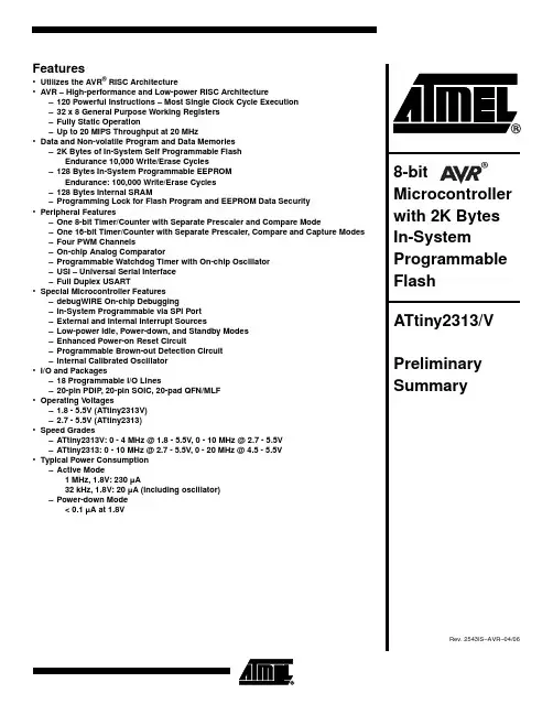
Features•Utilizes the AVR® RISC Architecture•AVR – High-performance and Low-power RISC Architecture –120 Powerful Instructions – Most Single Clock Cycle Execution –32 x 8 General Purpose Working Registers–Fully Static Operation–Up to 20 MIPS Throughput at 20 MHz•Data and Non-volatile Program and Data Memories–2K Bytes of In-System Self Programmable FlashEndurance 10,000 Write/Erase Cycles–128 Bytes In-System Programmable EEPROMEndurance: 100,000 Write/Erase Cycles–128 Bytes Internal SRAM–Programming Lock for Flash Program and EEPROM Data Security •Peripheral Features–One 8-bit Timer/Counter with Separate Prescaler and Compare Mode–One 16-bit Timer/Counter with Separate Prescaler, Compare and Capture Modes –Four PWM Channels–On-chip Analog Comparator–Programmable Watchdog Timer with On-chip Oscillator–USI – Universal Serial Interface–Full Duplex USART•Special Microcontroller Features–debugWIRE On-chip Debugging–In-System Programmable via SPI Port–External and Internal Interrupt Sources–Low-power Idle, Power-down, and Standby Modes–Enhanced Power-on Reset Circuit–Programmable Brown-out Detection Circuit–Internal Calibrated Oscillator•I/O and Packages–18 Programmable I/O Lines–20-pin PDIP, 20-pin SOIC, 20-pad QFN/MLF•Operating Voltages–1.8 - 5.5V (ATtiny2313V)–2.7 - 5.5V (ATtiny2313)•Speed Grades–ATtiny2313V: 0 - 4 MHz @ 1.8 - 5.5V, 0 - 10 MHz @ 2.7 - 5.5V–ATtiny2313: 0 - 10 MHz @ 2.7 - 5.5V, 0 - 20 MHz @ 4.5 - 5.5V•Typical Power Consumption–Active Mode1 MHz, 1.8V: 230 µA32 kHz, 1.8V: 20 µA (including oscillator)–Power-down Mode< 0.1 µA at 1.8V 8-bit Microcontroller2ATtiny2313/V2543IS–AVR–04/06Pin ConfigurationsFigure 1. Pinout ATtiny2313OverviewThe ATtiny2313 is a low-power CMOS 8-bit microcontroller based on the AVR enhanced RISC architecture. By executing powerful instructions in a single clock cycle,the ATtiny2313 achieves throughputs approaching 1 MIPS per MHz allowing the system designer to optimize power consumption versus processing speed.3ATtiny2313/V2543IS–AVR–04/06Block DiagramFigure 2. Block Diagram4ATtiny2313/V2543IS–AVR–04/06The AVR core combines a rich instruction set with 32 general purpose working registers.All the 32 registers are directly connected to the Arithmetic Logic Unit (ALU), allowing two independent registers to be accessed in one single instruction executed in one clock cycle. The resulting architecture is more code efficient while achieving throughputs up to ten times faster than conventional CISC microcontrollers.The ATtiny2313 provides the following features: 2K bytes of In-System Programmable Flash, 128 bytes EEPROM, 128 bytes SRAM, 18general purpose I/O lines, 32 general purpose working registers, a single-wire Interface for On-chip Debugging, two flexible Timer/Counters with compare modes, internal and external interrupts, a serial program-mable USART, Universal Serial Interface with Start Condition Detector, a programmable Watchdog Timer with internal Oscillator, and three software selectable power saving modes. The Idle mode stops the CPU while allowing the SRAM, Timer/Counters, and interrupt system to continue functioning. The Power-down mode saves the register con-tents but freezes the Oscillator, disabling all other chip functions until the next interrupt or hardware reset. In Standby mode, the crystal/resonator Oscillator is running while the rest of the device is sleeping. This allows very fast start-up combined with low-power consumption.The device is manufactured using Atmel’s high density non-volatile memory technology.The On-chip ISP Flash allows the program memory to be reprogrammed In-System through an SPI serial interface, or by a conventional non-volatile memory programmer.By combining an 8-bit RISC CPU with In-System Self-Programmable Flash on a mono-lithic chip, the Atmel ATtiny2313 is a powerful microcontroller that provides a highly flexible and cost effective solution to many embedded control applications.The ATtiny2313 AVR is supported with a full suite of program and system development tools including: C Compilers, Macro Assemblers, Program Debugger/Simulators, In-Cir-cuit Emulators, and Evaluation kits.5ATtiny2313/V2543IS–AVR–04/06Pin DescriptionsVCC Digital supply voltage.GNDGround.Port A (PA2..PA0)Port A is a 3-bit bi-directional I/O port with internal pull-up resistors (selected for each bit). The Port A output buffers have symmetrical drive characteristics with both high sink and source capability. As inputs, Port A pins that are externally pulled low will source current if the pull-up resistors are activated. The Port A pins are tri-stated when a reset condition becomes active, even if the clock is not running.Port A also serves the functions of various special features of the ATtiny2313 as listed on page 53.Port B (PB7..PB0)Port B is an 8-bit bi-directional I/O port with internal pull-up resistors (selected for each bit). The Port B output buffers have symmetrical drive characteristics with both high sink and source capability. As inputs, Port B pins that are externally pulled low will source current if the pull-up resistors are activated. The Port B pins are tri-stated when a reset condition becomes active, even if the clock is not running.Port B also serves the functions of various special features of the ATtiny2313 as listed on page 53.Port D (PD6..PD0)Port D is a 7-bit bi-directional I/O port with internal pull-up resistors (selected for each bit). The Port D output buffers have symmetrical drive characteristics with both high sink and source capability. As inputs, Port D pins that are externally pulled low will source current if the pull-up resistors are activated. The Port D pins are tri-stated when a reset condition becomes active, even if the clock is not running.Port D also serves the functions of various special features of the ATtiny2313 as listed on page 56.Reset input. A low level on this pin for longer than the minimum pulse length will gener-ate a reset, even if the clock is not running. The minimum pulse length is given in Table 15 on page 34. Shorter pulses are not guaranteed to generate a reset. The Reset Input is an alternate function for PA2 and dW.XTAL1Input to the inverting Oscillator amplifier and input to the internal clock operating circuit.XTAL1 is an alternate function for PA0.XTAL2Output from the inverting Oscillator amplifier. XTAL2 is an alternate function for PA1.ResourcesA comprehensive set of development tools, application notes and datasheets are avail-able for downloadon /avr.6ATtiny2313/V2543IS–AVR–04/06Register SummaryAddressNameBit 7Bit 6Bit 5Bit 4Bit 3Bit 2Bit 1Bit 0Page0x3F (0x5F)SREG I T H S V N Z C 70x3E (0x5E)Reserved ––––––––0x3D (0x5D)SPL SP7SP6SP5SP4SP3SP2SP1SP0100x3C (0x5C)OCR0B Timer/Counter0 – Compare Register B780x3B (0x5B)GIMSK INT1INT0PCIE –––––600x3A (0x5A)EIFR INTF1INTF0PCIF –––––620x39 (0x59)TIMSK TOIE1OCIE1A OCIE1B –ICIE1OCIE0B TOIE0OCIE0A 79, 1100x38 (0x58)TIFR TOV1OCF1A OCF1B –ICF1OCF0B TOV0OCF0A 790x37 (0x57)SPMCSR –––CTPB RFLB PGWRT PGERS SELFPRGEN1560x36 (0x56)OCR0A Timer/Counter0 – Compare Register A780x35 (0x55)MCUCR PUD SM1SE SM0ISC11ISC10ISC01ISC00530x34 (0x54)MCUSR ––––WDRF BORF EXTRF PORF 370x33 (0x53)TCCR0B FOC0A FOC0B ––WGM02CS02CS01CS00770x32 (0x52)TCNT0Timer/Counter0 (8-bit)780x31 (0x51)OSCCAL –CAL6CAL5CAL4CAL3CAL2CAL1CAL0250x30 (0x50)TCCR0A COM0A1COM0A0COM0B1COM0B0––WGM01WGM00740x2F (0x4F)TCCR1A COM1A1COM1A0COM1B1COM1BO ––WGM11WGM101050x2E (0x4E)TCCR1B ICNC1ICES1–WGM13WGM12CS12CS11CS101080x2D (0x4D)TCNT1H Timer/Counter1 – Counter Register High Byte 1090x2C (0x4C)TCNT1L Timer/Counter1 – Counter Register Low Byte 1090x2B (0x4B)OCR1AH Timer/Counter1 – Compare Register A High Byte 1090x2A (0x4A)OCR1AL Timer/Counter1 – Compare Register A Low Byte 1090x29 (0x49)OCR1BH Timer/Counter1 – Compare Register B High Byte 1100x28 (0x48)OCR1BL Timer/Counter1 – Compare Register B Low Byte1100x27 (0x47)Reserved ––––––––0x26 (0x46)CLKPR CLKPCE–––CLKPS3CLKPS2CLKPS1CLKPS0270x25 (0x45)ICR1H Timer/Counter1 - Input Capture Register High Byte 1100x24 (0x44)ICR1L Timer/Counter1 - Input Capture Register Low Byte1100x23 (0x43)GTCCR –––––––PSR10820x22 (ox42)TCCR1C FOC1A FOC1B ––––––1090x21 (0x41)WDTCSR WDIF WDIE WDP3WDCE WDE WDP2WDP1WDP0420x20 (0x40)PCMSK PCINT7PCINT6PCINT5PCINT4PCINT3PCINT2PCINT1PCINT0620x1F (0x3F)Reserved ––––––––0x1E (0x3E)EEAR –EEPROM Address Register 150x1D (0x3D)EEDR EEPROM Data Register160x1C (0x3C)EECR ––EEPM1EEPM0EERIE EEMPE EEPE EERE 160x1B (0x3B)PORTA –––––PORTA2PORTA1PORTA0580x1A (0x3A)DDRA –––––DDA2DDA1DDA0580x19 (0x39)PINA –––––PINA2PINA1PINA0580x18 (0x38)PORTB PORTB7PORTB6PORTB5PORTB4PORTB3PORTB2PORTB1PORTB0580x17 (0x37)DDRB DDB7DDB6DDB5DDB4DDB3DDB2DDB1DDB0580x16 (0x36)PINB PINB7PINB6PINB5PINB4PINB3PINB2PINB1PINB0580x15 (0x35)GPIOR2General Purpose I/O Register 2200x14 (0x34)GPIOR1General Purpose I/O Register 1200x13 (0x33)GPIOR0General Purpose I/O Register 0200x12 (0x32)PORTD –PORTD6PORTD5PORTD4PORTD3PORTD2PORTD1PORTD0580x11 (0x31)DDRD –DDD6DDD5DDD4DDD3DDD2DDD1DDD0580x10 (0x30)PIND –PIND6PIND5PIND4PIND3PIND2PIND1PIND0580x0F (0x2F)USIDR USI Data Register1450x0E (0x2E)USISR USISIF USIOIF USIPF USIDC USICNT3USICNT2USICNT1USICNT01460x0D (0x2D)USICR USISIE USIOIE USIWM1USIWM0USICS1USICS0USICLK USITC 1470x0C (0x2C)UDR UART Data Register (8-bit)1300x0B (0x2B)UCSRA RXC TXC UDRE FE DORUPE U2X MPCM 1300x0A (0x2A)UCSRB RXCIE TXCIE UDRIE RXEN TXENUCSZ2RXB8TXB81320x09 (0x29)UBRRL UBRRH[7:0]1340x08 (0x28)ACSR ACD ACBG ACO ACI ACIE ACIC ACIS1ACIS01500x07 (0x27)Reserved ––––––––0x06 (0x26)Reserved ––––––––0x05 (0x25)Reserved ––––––––0x04 (0x24)Reserved ––––––––0x03 (0x23)UCSRC –UMSEL UPM1UPM0USBSUCSZ1UCSZ0UCPOL1330x02 (0x22)UBRRH ––––UBRRH[11:8]1340x01 (0x21)DIDR ––––––AIN1D AIN0D 1510x00 (0x20)Reserved––––––––7ATtiny2313/V2543IS–AVR–04/06Note:1.For compatibility with future devices, reserved bits should be written to zero if accessed. Reserved I/O memory addressesshould never be written.2.I/O Registers within the address range 0x00 - 0x1F are directly bit-accessible using the SBI and CBI instructions. In theseregisters, the value of single bits can be checked by using the SBIS and SBIC instructions.3.Some of the status flags are cleared by writing a logical one to them. Note that, unlike most other AVRs, the CBI and SBIinstructions will only operate on the specified bit, and can therefore be used on registers containing such status flags. The CBI and SBI instructions work with registers 0x00 to 0x1F only.4.When using the I/O specific commands IN and OUT , the I/O addresses 0x00 - 0x3F must be used. When addressing I/ORegisters as data space using LD and ST instructions, 0x20 must be added to these addresses.8ATtiny2313/V2543IS–AVR–04/06Instruction Set SummaryMnemonicsOperandsDescriptionOperation Flags#ClocksARITHMETIC AND LOGIC INSTRUCTIONSADD Rd, Rr Add two RegistersRd ← Rd + RrZ,C,N,V,H 1ADC Rd, Rr Add with Carry two Registers Rd ← Rd + Rr + C Z,C,N,V,H 1ADIW Rdl,K Add Immediate to Word Rdh:Rdl ← Rdh:Rdl + K Z,C,N,V,S 2SUB Rd, Rr Subtract two RegistersRd ← Rd - Rr Z,C,N,V,H 1SUBI Rd, K Subtract Constant from Register Rd ← Rd - K Z,C,N,V,H 1SBC Rd, Rr Subtract with Carry two Registers Rd ← Rd - Rr - C Z,C,N,V,H 1SBCI Rd, K Subtract with Carry Constant from Reg.Rd ← Rd - K - C Z,C,N,V,H 1SBIW Rdl,K Subtract Immediate from Word Rdh:Rdl ← Rdh:Rdl - K Z,C,N,V,S 2AND Rd, Rr Logical AND RegistersRd ← Rd • Rr Z,N,V 1ANDI Rd, K Logical AND Register and Constant Rd ← Rd • K Z,N,V 1OR Rd, Rr Logical OR RegistersRd ← Rd v Rr Z,N,V 1ORI Rd, K Logical OR Register and Constant Rd ← Rd v K Z,N,V 1EOR Rd, Rr Exclusive OR Registers Rd ← Rd ⊕ Rr Z,N,V 1COM Rd One’s Complement Rd ← 0xFF − Rd Z,C,N,V 1NEG Rd Two’s Complement Rd ← 0x00 − Rd Z,C,N,V,H 1SBR Rd,K Set Bit(s) in Register Rd ← Rd v KZ,N,V 1CBR Rd,K Clear Bit(s) in Register Rd ← Rd • (0xFF - K)Z,N,V 1INC Rd Increment Rd ← Rd + 1Z,N,V 1DEC Rd DecrementRd ← Rd − 1 Z,N,V 1TST Rd Test for Zero or Minus Rd ← Rd • Rd Z,N,V 1CLR Rd Clear Register Rd ← Rd ⊕ Rd Z,N,V 1SER Rd Set Register Rd ← 0xFF None 1BRANCH INSTRUCTIONSRJMP kRelative Jump PC ← PC + k + 1None 2IJMP Indirect Jump to (Z)PC ← Z None 2RCALL kRelative Subroutine Call PC ← PC + k + 1None 3ICALL Indirect Call to (Z)PC ←Z None 3RET Subroutine Return PC ← STACK None 4RETI Interrupt Return PC ← STACKI 4CPSE Rd,Rr Compare, Skip if Equal if (Rd = Rr) PC ← PC + 2 or 3None 1/2/3CP Rd,Rr CompareRd − Rr Z, N,V,C,H 1 CPC Rd,Rr Compare with CarryRd − Rr − C Z, N,V,C,H 1CPI Rd,K Compare Register with Immediate Rd − KZ, N,V,C,H 1SBRC Rr, b Skip if Bit in Register Cleared if (Rr(b)=0) PC ← PC + 2 or 3 None 1/2/3SBRS Rr, b Skip if Bit in Register is Set if (Rr(b)=1) PC ← PC + 2 or 3None 1/2/3SBIC P, b Skip if Bit in I/O Register Cleared if (P(b)=0) PC ← PC + 2 or 3 None 1/2/3SBIS P, b Skip if Bit in I/O Register is Set if (P(b)=1) PC ← PC + 2 or 3None 1/2/3BRBS s, k Branch if Status Flag Set if (SREG(s) = 1) then PC ←PC+k + 1None 1/2BRBC s, k Branch if Status Flag Cleared if (SREG(s) = 0) then PC ←PC+k + 1None 1/2BREQ k Branch if Equal if (Z = 1) then PC ← PC + k + 1None 1/2BRNE k Branch if Not Equal if (Z = 0) then PC ← PC + k + 1None 1/2BRCS k Branch if Carry Set if (C = 1) then PC ← PC + k + 1None 1/2BRCC k Branch if Carry Cleared if (C = 0) then PC ← PC + k + 1None 1/2BRSH k Branch if Same or Higher if (C = 0) then PC ← PC + k + 1None 1/2BRLO k Branch if Lower if (C = 1) then PC ← PC + k + 1None 1/2BRMI k Branch if Minus if (N = 1) then PC ← PC + k + 1None 1/2BRPL k Branch if Plusif (N = 0) then PC ← PC + k + 1None 1/2BRGE k Branch if Greater or Equal, Signed if (N ⊕ V= 0) then PC ← PC + k + 1None 1/2BRLT k Branch if Less Than Zero, Signed if (N ⊕ V= 1) then PC ← PC + k + 1None 1/2BRHS k Branch if Half Carry Flag Set if (H = 1) then PC ← PC + k + 1None 1/2BRHC k Branch if Half Carry Flag Cleared if (H = 0) then PC ← PC + k + 1None 1/2BRTS k Branch if T Flag Set if (T = 1) then PC ← PC + k + 1None 1/2BRTC k Branch if T Flag Cleared if (T = 0) then PC ← PC + k + 1None 1/2BRVS k Branch if Overflow Flag is Set if (V = 1) then PC ← PC + k + 1None 1/2BRVC k Branch if Overflow Flag is Cleared if (V = 0) then PC ← PC + k + 1None 1/2BRIE k Branch if Interrupt Enabled if ( I = 1) then PC ← PC + k + 1None 1/2BRID k Branch if Interrupt Disabled if ( I = 0) then PC ← PC + k + 1None 1/2BIT AND BIT-TEST INSTRUCTIONSSBI P,b Set Bit in I/O Register I/O(P,b) ←1None 2CBI P,b Clear Bit in I/O Register I/O(P,b) ← 0None 2LSL Rd Logical Shift Left Rd(n+1) ← Rd(n), Rd(0) ← 0Z,C,N,V 1LSR Rd Logical Shift Right Rd(n) ← Rd(n+1), Rd(7) ← 0Z,C,N,V 1ROLRd Rotate Left Through CarryRd(0)←C,Rd(n+1)← Rd(n),C ←Rd(7)Z,C,N,V19ATtiny2313/V2543IS–AVR–04/06ROR Rd Rotate Right Through CarryRd(7)←C,Rd(n)← Rd(n+1),C ←Rd(0)Z,C,N,V 1ASR Rd Arithmetic Shift Right Rd(n) ← Rd(n+1), n=0..6Z,C,N,V 1SWAP Rd Swap Nibbles Rd(3..0)←Rd(7..4),Rd(7..4)←Rd(3..0)None 1BSET s Flag Set SREG(s) ← 1SREG(s)1BCLR s Flag ClearSREG(s) ← 0 SREG(s)1BST Rr, b Bit Store from Register to T T ← Rr(b)T 1BLD Rd, bBit load from T to Register Rd(b) ← T None 1SEC Set Carry C ←1C 1CLC Clear Carry C ← 0 C 1SEN Set Negative Flag N ←1N 1CLN Clear Negative Flag N ← 0 N 1SEZ Set Zero Flag Z ← 1Z 1CLZ Clear Zero Flag Z ← 0 Z 1SEI Global Interrupt Enable I ←1I 1CLI Global Interrupt Disable I ← 0 I 1SES Set Signed Test Flag S ← 1S 1CLS Clear Signed Test FlagS ← 0 S 1SEV Set Twos Complement Overflow.V ← 1V 1CLV Clear Twos Complement Overflow V ← 0 V 1SET Set T in SREG T ←1T 1CLT Clear T in SREGT ← 0T 1SEH Set Half Carry Flag in SREGH ←1H 1CLHClear Half Carry Flag in SREGH ← 0H1DATA TRANSFER INSTRUCTIONS MOV Rd, Rr Move Between RegistersRd ← Rr None 1MOVW Rd, Rr Copy Register Word Rd+1:Rd ← Rr+1:Rr None 1LDI Rd, K Load Immediate Rd ← KNone 1LD Rd, X Load Indirect Rd ← (X)None 2LD Rd, X+Load Indirect and Post-Inc.Rd ← (X), X ← X + 1None 2LD Rd, - X Load Indirect and Pre-Dec.X ← X - 1, Rd ← (X)None 2LD Rd, Y Load IndirectRd ← (Y)None 2LD Rd, Y+Load Indirect and Post-Inc.Rd ← (Y), Y ← Y + 1None 2LD Rd, - Y Load Indirect and Pre-Dec.Y ← Y - 1, Rd ← (Y)None 2LDD Rd,Y+q Load Indirect with Displacement Rd ← (Y + q)None 2LD Rd, Z Load Indirect Rd ← (Z)None 2LD Rd, Z+Load Indirect and Post-Inc.Rd ← (Z), Z ← Z+1None 2LD Rd, -Z Load Indirect and Pre-Dec.Z ← Z - 1, Rd ← (Z)None 2LDD Rd, Z+q Load Indirect with Displacement Rd ← (Z + q)None 2LDS Rd, k Load Direct from SRAM Rd ← (k)None 2ST X, Rr Store Indirect(X) ← RrNone 2ST X+, Rr Store Indirect and Post-Inc.(X) ← Rr, X ← X + 1None 2ST - X, Rr Store Indirect and Pre-Dec.X ← X - 1, (X) ← Rr None 2ST Y, Rr Store Indirect(Y) ← RrNone 2ST Y+, Rr Store Indirect and Post-Inc.(Y) ← Rr, Y ← Y + 1None 2ST - Y, Rr Store Indirect and Pre-Dec.Y ← Y - 1, (Y) ← Rr None 2STD Y+q,Rr Store Indirect with Displacement (Y + q) ← Rr None 2ST Z, Rr Store Indirect(Z) ← RrNone 2ST Z+, Rr Store Indirect and Post-Inc.(Z) ← Rr, Z ← Z + 1None 2ST -Z, Rr Store Indirect and Pre-Dec.Z ← Z - 1, (Z) ← Rr None 2STD Z+q,Rr Store Indirect with Displacement (Z + q) ← Rr None 2STS k, RrStore Direct to SRAM (k) ← Rr None 2LPM Load Program Memory R0 ← (Z)None 3LPM Rd, Z Load Program MemoryRd ← (Z)None 3LPM Rd, Z+Load Program Memory and Post-Inc Rd ← (Z), Z ← Z+1None 3SPM Store Program Memory (Z) ← R1:R0None -IN Rd, P In Port Rd ←P None 1OUT P, Rr Out PortP ← Rr None 1PUSH Rr Push Register on Stack STACK ← Rr None 2POP Rd Pop Register from Stack Rd ← STACKNone 2MCU CONTROL INSTRUCTIONSNOP No Operation None 1SLEEP Sleep(see specific descr. for Sleep function)None 1WDR Watchdog Reset (see specific descr. for WDR/timer)None 1BREAKBreakFor On-chip Debug Only NoneN/AMnemonicsOperandsDescriptionOperationFlags#Clocks10ATtiny2313/V2543IS–AVR–04/06Ordering InformationNote:1.This device can also be supplied in wafer form. Please contact your local Atmel sales office for detailed ordering informationand minimum quantities.2.Pb-free packaging alternative, complies to the European Directive for Restriction of Hazardous Substances (RoHS direc-tive).Also Halide free and fully Green.3.For Speed vs. V CC, see Figure 82 on page 181 and Figure 83 on page 181.Speed (MHz)(3)Power SupplyOrdering Code Package (1)Operation Range10 1.8 - 5.5VA Ttiny2313V-10PI A Ttiny2313V-10PU (2)A Ttiny2313V-10SI A Ttiny2313V-10SU (2)A Ttiny2313V-10MU (2)20P320P320S 20S 20M1Industrial (-40°C to 85°C)20 2.7 - 5.5VA Ttiny2313-20PI A Ttiny2313-20PU (2)A Ttiny2313-20SI A Ttiny2313-20SU (2)A Ttiny2313-20MU (2)20P320P320S 20S 20M1Industrial (-40°C to 85°C)Package Type20P320-lead, 0.300" Wide, Plastic Dual Inline Package (PDIP)20S 20-lead, 0.300" Wide, Plastic Gull Wing Small Outline Package (SOIC)20M120-pad, 4 x 4 x 0.8 mm Body, Quad Flat No-Lead/Micro Lead Frame Package (MLF)11ATtiny2313/V2543IS–AVR–04/06Packaging Information20P312ATtiny2313/V2543IS–AVR–04/0620S13ATtiny2313/V2543IS–AVR–04/0620M114ATtiny2313/V2543IS–AVR–04/06ErrataThe revision in this section refers to the revision of the ATtiny2313 device.ATtiny2313 Rev B•Wrong values read after Erase Only operation •Parallel Programming does not work •Watchdog Timer Interrupt disabled•EEPROM can not be written below 1.9 volts1.Wrong values read after Erase Only operationAt supply voltages below 2.7 V, an EEPROM location that is erased by the Erase Only operation may read as programmed (0x00).Problem Fix/WorkaroundIf it is necessary to read an EEPROM location after Erase Only, use an Atomic Write operation with 0xFF as data in order to erase a location. In any case, the Write Only operation can be used as intended. Thus no special considerations are needed as long as the erased location is not read before it is programmed.2.Parallel Programming does not workParallel Programming is not functioning correctly. Because of this, reprogramming of the device is impossible if one of the following modes are selected: –In-System Programming disabled (SPIEN unprogrammed)–Reset Disabled (RSTDISBL programmed)Problem Fix/WorkaroundSerial Programming is still working correctly. By avoiding the two modes above, the device can be reprogrammed serially.3.Watchdog Timer Interrupt disabledIf the watchdog timer interrupt flag is not cleared before a new timeout occurs, the watchdog will be disabled, and the interrupt flag will automatically be cleared. This is only applicable in interrupt only mode. If the Watchdog is configured to reset the device in the watchdog time-out following an interrupt, the device works correctly.Problem fix / WorkaroundMake sure there is enough time to always service the first timeout event before a new watchdog timeout occurs. This is done by selecting a long enough time-out period.4.EEPROM can not be written below 1.9 voltsWriting the EEPROM at V CC below 1.9 volts might fail.Problem fix / WorkaroundDo not write the EEPROM when V CC is below 1.9 volts.ATtiny2313 Rev ARevision A has not been sampled.15ATtiny2313/V2543IS–AVR–04/06Datasheet Revision HistoryPlease note that the referring page numbers in this section are referred to this docu-ment. The referring revision in this section are referring to the document revision.Changes from Rev. 2514H-02/05 to Rev. 2514I-04/06Changes from Rev. 2514G-10/04 to Rev. 2514H-02/05Changes from Rev. 2514F-08/04 to Rev. 2514G-10/04Changes from Rev. 2514E-04/04 to Rev. 2514F-08/041.Updated typos.2.Updated Figure 1 on page 2.3Added “Resources” on page 6.4.Updated “Default Clock Source” on page 25.5.Updated “128 kHz Internal Oscillator” on page 30.6.Updated “Power Management and Sleep Modes” on page 337.Updated Table 3 on page 25,Table 13 on page 33, Table 14 on page 34,Table 19 on page 45, Table 31 on page 63, Table 79 on page 180.8.Updated “External Interrupts” on page 62.9.Updated “Bit 7..0 – PCINT7..0: Pin Change Enable Mask 7..0” on page 65.10.Updated “Bit 6 – ACBG: Analog Comparator Bandgap Select” on page 153.11.Updated “Calibration Byte” on page 164.12.Updated “DC Characteristics” on page 181.13.Updated “Register Summary” on page 6.14.Updated “Ordering Information” on page 10.15.Changed occurences of OCnA to OCFnA, OCnB to OCFnB and OC1x to OCF1x.1.Updated Table 6 on page 24, Table 15 on page 34, Table 68 on page 161and Table 80 on page 180.2.Changed CKSEL default value in “Default Clock Source” on page 22 to 8 MHz.3.Updated “Programming the Flash” on page 166, “Programming the EEPROM” on page 168 and “Enter Programming Mode” on page 164.4.Updated “DC Characteristics” on page 178.5.MLF option updated to “Quad Flat No-Lead/Micro Lead Frame (QFN/MLF)”1.Updated “Features” on page 1.2.Updated “Pinout ATtiny2313” on page 2.3.Updated “Ordering Information” on page 10.4.Updated “Packaging Information” on page 11.5.Updated “Errata” on page 14.1.Updated “Features” on page 1.2.Updated “Alternate Functions of Port B” on page 53.3.Updated “Calibration Byte” on page 161.16ATtiny2313/V2543IS–AVR–04/06Changes from Rev. 2514D-03/04 to Rev. 2514E-04/04Changes from Rev. 2514C-12/03 to Rev. 2514D-03/04Changes from Rev. 2514B-09/03 to Rev. 2514C-12/03Changes from Rev. 2514A-09/03 to Rev. 2514B-09/034.Moved Table 69 on page 161 and Table 70 on page 162 to “Page Size”on page 161.5.Updated “Enter Programming Mode” on page 164.6.Updated “Serial Programming Algorithm” on page 174.7.Updated Table 78 on page 175.8.Updated “DC Characteristics” on page 178.9.Updated “ATtiny2313 Typical Characteristics” on page 182.10.Changed occurences of PCINT15 to PCINT7, EEMWE to EEMPE and EEWE to EEPE in the document.1.Speed Grades changed - 12MHz to 10MHz - 24MHz to 20MHz2.Updated Figure 1 on page 2.3.Updated “Ordering Information” on page 10.4.Updated “Maximum Speed vs. V CC ” on page 181.5.Updated “ATtiny2313 Typical Characteristics” on page 182.1.Updated Table 2 on page 22.2.Replaced “Watchdog Timer” on page 39.3.Added “Maximum Speed vs. V CC ” on page 181.4.“Serial Programming Algorithm” on page 174 updated.5.Changed mA to µA in preliminary Figure 136 on page 208.6.“Ordering Information” on page 10 updated. MLF package option removed7.Package drawing “20P3” on page 11 updated.8.Updated C-code examples.9.Renamed instances of SPMEN to SELFPRGEN, Self Programming Enable.1.Updated “Calibrated Internal RC Oscillator” on page 24.1.Fixed typo from UART to USART and updated Speed Grades and Power Consumption Estimates in “Features” on page 1.2.Updated “Pin Configurations” on page 2.3.Updated Table 15 on page 34 and Table 80 on page 180.4.Updated item 5 in “Serial Programming Algorithm” on page 174.5.Updated “Electrical Characteristics” on page 178.6.Updated Figure 82 on page 181 and added Figure 83 on page 181.7.Changed SFIOR to GTCCR in “Register Summary” on page 6.8.Updated “Ordering Information” on page 10.9.Added new errata in “Errata” on page 14.2543IS–AVR–04/06© Atmel Corporation 2006. All rights reserved. Atmel ®, logo and combinations thereof, Everywhere You Are ®, AVR ®, AVR Studio ®, and others,are registered trademarks or trademarks of Atmel Corporation or its subsidiaries. Other terms and product names may be trademarks of others.Disclaimer: The information in this document is provided in connection with Atmel products. No license, express or implied, by estoppel or otherwise,to any intellectual property right is granted by this document or in connection with the sale of Atmel products. EXCEPT AS SET FORTH IN ATMEL ’S TERMS AND CONDI-TIONS OF SALE LOCATED ON ATMEL ’S WEB SITE, ATMEL ASSUMES NO LIABILITY WHATSOEVER AND DISCLAIMS ANY EXPRESS, IMPLIED OR STATUTORY WARRANTY RELATING TO ITS PRODUCTS INCLUDING, BUT NOT LIMITED TO, THE IMPLIED WARRANTY OF MERCHANTABILITY, FITNESS FOR A PARTICULAR PURPOSE, OR NON-INFRINGEMENT. IN NO EVENT SHALL ATMEL BE LIABLE FOR ANY DIRECT, INDIRECT, CONSEQUENTIAL, PUNITIVE, SPECIAL OR INCIDEN-TAL DAMAGES (INCLUDING, WITHOUT LIMITATION, DAMAGES FOR LOSS OF PROFITS, BUSINESS INTERRUPTION, OR LOSS OF INFORMATION) ARISING OUT OF THE USE OR INABILITY TO USE THIS DOCUMENT, EVEN IF ATMEL HAS BEEN ADVISED OF THE POSSIBILITY OF SUCH DAMAGES. Atmel makes no representations or warranties with respect to the accuracy or completeness of the contents of this document and reserves the right to make changes to specifications and product descriptions at any time without notice. Atmel does not make any commitment to update the information contained herein. Unless specifically provided otherwise, Atmel products are not suitable for, and shall not be used in, automotive applications. Atmel’s products are not intended, authorized, or warranted for use as components in applications intended to support or sustain life.Atmel CorporationAtmel Operations2325 Orchard Parkway San Jose, CA 95131, USA Tel: 1(408) 441-0311Fax: 1(408) 487-2600Regional HeadquartersEuropeAtmel SarlRoute des Arsenaux 41Case Postale 80CH-1705 Fribourg SwitzerlandTel: (41) 26-426-5555Fax: (41) 26-426-5500AsiaRoom 1219Chinachem Golden Plaza 77 Mody Road Tsimshatsui East Kowloon Hong KongTel: (852) 2721-9778Fax: (852) 2722-1369Japan9F, Tonetsu Shinkawa Bldg.1-24-8 ShinkawaChuo-ku, Tokyo 104-0033JapanTel: (81) 3-3523-3551Fax: (81) 3-3523-7581Memory2325 Orchard Parkway San Jose, CA 95131, USA Tel: 1(408) 441-0311Fax: 1(408) 436-4314Microcontrollers2325 Orchard Parkway San Jose, CA 95131, USA Tel: 1(408) 441-0311Fax: 1(408) 436-4314La Chantrerie BP 7060244306 Nantes Cedex 3, France Tel: (33) 2-40-18-18-18Fax: (33) 2-40-18-19-60ASIC/ASSP/Smart CardsZone Industrielle13106 Rousset Cedex, France Tel: (33) 4-42-53-60-00Fax: (33) 4-42-53-60-011150 East Cheyenne Mtn. Blvd.Colorado Springs, CO 80906, USA Tel: 1(719) 576-3300Fax: 1(719) 540-1759Scottish Enterprise Technology Park Maxwell BuildingEast Kilbride G75 0QR, Scotland Tel: (44) 1355-803-000Fax: (44) 1355-242-743RF/AutomotiveTheresienstrasse 2Postfach 353574025 Heilbronn, Germany Tel: (49) 71-31-67-0Fax: (49) 71-31-67-23401150 East Cheyenne Mtn. Blvd.Colorado Springs, CO 80906, USA Tel: 1(719) 576-3300Fax: 1(719) 540-1759Biometrics/Imaging/Hi-Rel MPU/High Speed Converters/RF DatacomAvenue de Rochepleine BP 12338521 Saint-Egreve Cedex, France Tel: (33) 4-76-58-30-00Fax: (33) 4-76-58-34-80Literature Requests/literature。

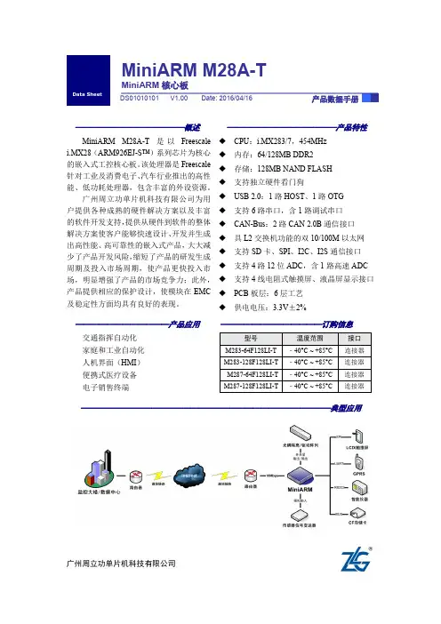
广州周立功单片机科技有限公司修订历史目录1. 产品简介 (1)1.1产品特性 (1)1.2产品命名 (2)1.3产品选型 (2)1.4性能参数 (3)2. 硬件结构 (5)2.1I/O引脚信息 (5)2.2管脚说明(按管脚顺序划分) (6)2.3管脚说明(按功能定义划分) (11)2.4管脚说明(按管脚复用划分) (14)3. 电气参数 (18)3.1供电参数 (18)3.2PSWITCH输入特性 (18)3.3GPIO电气参数 (18)3.4ADC电气特性 (19)4. 典型应用 (20)5. 产品图片 (21)6. 机械尺寸 (22)7. 免责声明 (23)1. 产品简介MiniARM M28A-T核心板是广州周立功单片机科技有限公司精心设计的一款低功耗、高性能的核心板。
核心板处理器采用飞思卡尔基于ARM9内核的i.MX28系列芯片,主频454MHz,支持UART、I2C、I2S、Ethernet、USB、SSP等众多通讯接口,并支持16位TFT 液晶显示和电阻式触摸屏,适用于通用嵌入式工业控制和消费电子市场。
处理器集成电源管理单元,可有效简化系统电源设计,降低成本,减小系统功耗,使得该处理器非常适用于低成本、低功耗、高性能的便携设备。
MiniARM M28A-T核心板集成了DDR2、NAND Flash、硬件看门狗等,可有效缩短用户基于M28A-T核心板进行产品开发的周期。
核心板通过严格的EMC和高低温测试,保证核心板在严酷的环境下也能稳定工作。
1.1 产品特性◆CPU:Freescale i.MX283/ i.MX287;◆运行频率:454MHz;◆支持64/128M DDR2;◆支持64/128MB NAND FLASH;◆内置电源管理单元-PMU;◆内置TCP/IP协议栈;◆支持独立硬件看门狗;◆支持多种文件系统,支持SD/MMC卡、U盘读写;◆支持1路USB2.0 HOST、1路USB2.0 OTG;◆支持2路10M/100M以太网接口,支持交换机功能;◆支持多达6路串口、2路CAN;◆支持1路SD Card接口,1路SDIO;◆1路I²C、1路SPI、1路I²S及4路12位ADC;◆内置LCD控制器,分辨率最高达800×480;◆支持4线电阻式触摸屏接口;◆支持JTAG调试接口;◆支持多种升级方式;◆采用6层PCB工艺;◆尺寸30mm×48mm;◆低工作电压:3.3V±2%;◆采用高精度板对板连接器;◆所有元器件均符合工业级-40℃~+85℃要求。

L P C1100系列微控制器第第十十六六章章模模数数转转换换器器用用户户手手册册R R e e v v11..0000地址:广州市天河北路689号光大银行大厦12楼F4网址:销售与服务网络广州周立功单片机发展有限公司地址:广州市天河北路689号光大银行大厦12楼F4 邮编:510630 电话:(020)38730972 38730976 38730916 38730917 38730977 传真:(020)38730925网址:广州专卖店地址:广州市天河区新赛格电子城203-204室电话:(020)87578634 87569917传真:(020)87578842南京周立功地址:南京市珠江路280号珠江大厦2006室电话:(025)83613221 83613271 83603500 传真:(025)83613271北京周立功地址:北京市海淀区知春路113号银网中心A座1207-1208室(中发电子市场斜对面)电话:(010)62536178 62536179 82628073传真:(010)82614433 重庆周立功地址:重庆市石桥铺科园一路二号大西洋国际大厦(赛格电子市场)1611室电话:(023)68796438 68796439传真:(023)68796439杭州周立功地址:杭州市天目山路217号江南电子大厦502室电话:(0571)28139611 28139612 2813961328139615 28139616 28139618传真:(0571)28139621 成都周立功地址:成都市一环路南二段1号数码同人港401室(磨子桥立交西北角)电话:(028)85439836 85437446传真:(028) 85437896深圳周立功地址:深圳市深南中路 2070号电子科技大厦C座4楼D室电话:(0755)83781788(5线)传真:(0755)83793285 武汉周立功地址:武汉市洪山区广埠屯珞瑜路158号12128室(华中电脑数码市场)电话:(027)87168497 87168297 87168397传真:(027)87163755上海周立功地址:上海市北京东路668号科技京城东座7E室电话:(021)53083452 53083453 53083496传真:(021)53083491西安办事处地址:西安市长安北路54号太平洋大厦1201室电话:(029)87881296 83063000 87881295传真:(029)87880865目录第16章 ADC (2)16.1 本章导读 (2)16.2 特性 (2)16.3 管脚描述 (2)16.4 时钟供应和功率控制 (2)16.5 寄存器描述 (2)16.5.1 A/D控制寄存器 (3)16.5.2 A/D全局数据寄存器 (5)16.5.3 A/D状态寄存器 (5)16.5.4 A/D中断使能寄存器 (5)16.5.5 A/D数据寄存器 (6)16.6 操作 (6)16.6.1 硬件触发转换 (6)16.6.2 中断 (6)16.6.3 精度和数字接收器 (6)第16章ADC 16.1 本章导读所有LPC1100系列ARM的ADC块都相同。
第1章 MagicARM2200-S教学实验开发平台1.1总体特性MagicARM2200-S是专为高校嵌入式系统教学精心打造的ARM嵌入式教学实验开发平台,支持多种嵌入式操作系统,提供丰富的配套教材和众多的实验例程,提供多种的商业化软件包,并配备精心设计的多媒体教学课件,是高校嵌入式系统创新实验室首选平台。
z多种可选嵌入式硬件开发平台¾ARM7微处理器(LPC2210/2212/2214/2220/2290/2292/2294)¾ARM9微处理器(LPC3000系列ARM微处理器)z支持多种可选嵌入式操作系统¾μC/OS-II嵌入式实时操作系统(ARM7/ARM9)¾μCLinux操作系统(ARM7)¾Linux/操作系统(ARM9)z配套丰富的教材《ARM嵌入式系统基础教程》(标配)《MagicARM2200-S教学实验开发平台实验指导(上册)》(标配)《MagicARM2200-S教学实验开发平台实验指导(下册)》(标配)《ARM嵌入式软件开发实例(一)》(选配)《ARM嵌入式软件开发实例(二)》(选配)《ARM嵌入式µCLinux系统构建与驱动开发范例》(选配)《ARM嵌入式MiniGUI初步与应用开发范例》(选配)z多媒体教学课件¾耗时半年之久,倾力制作¾大量动画突出重点和难点,层层剥笋由浅入深¾紧扣教材主线,任君裁剪z丰富翔实的联机实验指导¾在本机上运行,无需电脑。
¾可以从多种介质中启动程序,方便扩充。
¾支持从内部FALSH、CF卡/硬盘。
¾内容丰富,可部分替代实验教材。
¾可直接运行实验程序,察看运行效果。
z附带众多源码和软件包¾众多实验例程和源代码¾众多商业化软件包z免费捆绑MiniGUI学习版软件(单独销价129元)¾北京飞漫出品,周立功公司独家代理¾提供MiniGUI for µCLinux移植实验,MiniGUI应用实例¾免费提供MiniGUI-STR软件包z可进实现近众多项实验课题¾基础实验¾扩展实验¾基于μC/OS-II的基础实验¾基于μCLinux基础实验¾MiniGUI图形界面实验¾课程设计¾毕业设计1.2产品外观实验箱和配套资料1.3主板介绍MagicARM2200-S主板图片见附录部分。
文件信息 类别内容关键词I 2C 总线、概要摘要现在,已经有越来越多的外围器件与微控制器的接口形式是二线制的I 2C 串行总线,学会其基本操作已经成为广大电子电气工程师和爱好者的迫切要求。
鉴于I 2C 总线协议原文内容十分详尽,对于总线协议的初学者可能不易把握,本文特意非常简要地介绍了I 2C 总线的概念、优点和基础协议,可以帮助您尽快掌握具体器件的用法,也为进一步深入学习掌握I 2C 总线打好基础。
广州周立功单片机发展有限公司周立功单片机技术支持如果您对文档中的产品感兴趣,或者对文档有所疑问,您可以在办公时间(星期一至星期五上午8:30~11:50;下午1:30~5:30;星期六上午8:30~11:50)拨打技术支持电话或E-mail 联系。
网址: 联系电话:+86 (020) 22644358 22644359 22644360 22644361E-mail:zlgmcu.support@销售与服务网络广州周立功单片机发展有限公司地址:广州市天河北路689号光大银行大厦15楼F1 邮编:510630电话:(020)38730916 38730917 38730976 38730977传真:(020)38730925网址:广州专卖店地址:广州市天河区新赛格电子城203-204室电话:(020)87578634 87569914传真:(020)87578842南京周立功地址:南京市珠江路280号珠江大厦2006室电话:(025)83613221 83613271 83603500 传真:(025)83613271北京周立功地址:北京市海淀区知春路113号银网中心715室(中发电子市场斜对面)电话:(010)62536178 62536179 82628073传真:(010)82614433 重庆周立功地址:重庆市石桥铺科园一路二号大西洋国际大厦(赛格电子市场)1115室电话:(023)68796438 68796439传真:(023)68796439杭州周立功地址:杭州市登云路428号浙江时代电子市场205号电话:(0571)88009205 88009932 88009933传真:(0571)88009204成都周立功地址:成都市一环路南一段57号金城大厦612室电话:(028)85399320 85437446传真:(028)85439505深圳周立功地址:深圳市深南中路 2070号电子科技大厦A座24楼2403室电话:(0755)83781768 83781788 83782922传真:(0755)83793285武汉周立功地址:武汉市洪山区广埠屯珞瑜路158号12128室(华中电脑数码市场)电话:(027)87168497 87168297 87168397传真:(027)87163755上海周立功地址:上海市北京东路668号科技京城东座7E室电话:(021)53083452 53083453 53083496传真:(021)53083491西安办事处地址:西安市长安北路54号太平洋大厦1201室电话:(029)87881296 83063000 85399492传真:(029)87880865I2C总线概要现在,已经有越来越多的外围器件与微控制器的接口形式是二线制的I2C串行总线,学会其基本操作已经成为广大电子电气工程师和爱好者的迫切要求。
NETCOM-10S/M 产品使用说明书Version 1.0目录第1章NETCOM-10 功能简介 (3)第2章NETCOM-10 硬件电路说明 (5)第3章硬件连接使用说明 (8)第4章软件配置使用说明 (9)第5章网页配置说明 (24)附录1 TCP和UDP中默认已经被占用的端口列表 (31)附录2 NETCOM-10速度测试结果 (32)附录3 技术支持E-MAIL及产品问题报告表 (33)附录4产品返修程序 (35)第1章NETCOM-10 模块功能简介NETCOM-10是周立功公司开发的一款TCP/IP以太网转串口设备,它内部集成了TCP/IP协议栈,用户利于它可以轻松完成嵌入式设备的网络功能,节省人力物力和开发时间,使产品更快的投入市场,增强竞争力。
功能特点:z RS232(或RS485/RS422)to 10M Ethernet,Serial最大波特率为230400 bps;z可利用Web browser和Windows utility 轻松进行设定;z TCP Server,TCP Client, UDP, Real COM ,Group组播,TCP Auto等作业模式;z支持动态(DHCP) ;或静态获取IP地址;产品特性:z 32位ARM7 CPU;z 16KB RAM;z 256KB FLASH;z 10M以太网RJ45接口;z 1.5KV 电磁隔离;z NETCOM-10S为RS232三线方式,NETCOM-10M为RS485/RS422,波特率300~230400 bps;z串口任意校验;z串口数据位5,6,7,8可设定;z串口停止位1,2位可设定;z支持TCP/IP协议包括:ETHERNET、ARP、IP、ICMP、IGMP、UDP、TCP、HTTP、DHCP;z工作方式可选择为TCP Server, TCP Client, UDP, Real COM driver,Group Mode,TCP Auto,组播地址、工作端口、目标IP和端口均可设定,支持PairConnection 对连方式工作;z提供JAVA控制库,用户可编写自己的网页进行控制,提供112KB字节网页下载空间;z提供Real COM driver模式下的管理软件,可动态修改串口参数,真正实现虚拟串口;z提供Group Mode组播模式下的数据分组广播,实现多机通讯;z提供串口起始字节和结束字节分包功能;z可使用配置工具ZnetCom Utility for Windows98/me/NT/2000/XP进行配置;z另外提供通用配置函数库,方便用户使用VC、VB、Delphi和C++ Builder开发应用程序z可使用网页浏览器进行配置;z输入电压9~30Vz功耗低最大工作电流 95 mAz工作温度0~65ºCz保存温度-25~85ºC第2章NETCOM-10硬件电路说明下面我们分别介绍NETCOM-10的接口的使用。
ISA-5420智能CAN接口卡用户手册 V1.0广州周立功单片机发展有限公司2003年12月18日目录一 功能特点---------------------------------------------------------------1 三 设备安装---------------------------------------------------------------24.1 硬件安装------------------------------------------------------------24.2 DB9针型插座引脚定义----------------------------------------------34.3 随卡软件包的安装---------------------------------------------------44.3.1 安装软件包------------------------------------------------------------------------44.3.2 安装驱动程序----------------------------------------------------------------------44.3.2.1 在Win98/Me系统下安装-------------------------------------------------------44.3.2.2 在DOS下安装------------------------------------------------------------------9 五 测试工具-------------------------------------------------------------22 七 产品服务-------------------------------------------------------------238.1 保修期--------------------------------------------------------------238.2 保修政策包括的范围---------------------------------------------------238.3 保修政策不包括的范围-------------------------------------------------238.4 软件升级----------------------------------------------------------------------------238.5 技术支持----------------------------------------------------------------------------23附录ACAN2.0B协议帧格式-------------------------------------------------26 附录C一其产权受国家拷贝法律绝对保护其他公司代理商及个人不得非法使用和您若需要我公司产品及相关信息我们将热情接待二它使PC机方便地连接到CAN总线上ISA-5420智能CAN接口卡采用标准ISA接口接口卡上自带光电隔离模块增强系统在恶劣环境中使用的可靠性Win98/Me下工作的驱动程序使开发简单化C++BuilderVB三图 3.1 ISA-5420智能CAN接口卡3.2 参数l 板载数据存储器 l CAN控制器 l CAN收发器 l 数据传送速率范围在5Kbit/sl CAN通讯接口符合DeviceNET和CANopen标准CAN 2.0B规范l 最高帧流量1000VDCl物理尺寸 98mmDOSISA3.3 软件支持 ISAÖ§³ÖWin98/Me 操作系统实现CAN 协议2.0B 规范的数据通讯5420智能CAN 接口卡提供功能强大的接口函数库文件5420智能CAN 接口卡自由发放相应的驱动程序及应用程序文件5420智能CAN 接口卡还支持DOS 下大模式的静态库3.4 产品清单 l ISADLL 库使用例程1份lISAÑ¡¼þÉ豸°²×°4.1 硬件安装l ISA-5420智能CAN 接口卡是属于静电敏感产品因此请注意采取必要的防护措施在PC 不通电的状态下将ISA-5420智能CAN 接口卡插入任一空闲的ISA 插槽同样l 在实物板卡上通过跳线JP2设置中断号总共有4位开关ON打到另一边表示1图4.1 选址内存范围内存范围表格如下所示H-6 0 1 1 0 0x0d8000 H-7 0 1 1 1 0x0dc000 H-8 1 0 0 0 0x0e0000 H-9 1 0 0 1 0x0e4000 H-A 1 0 1 0 0x0e8000 H-B 1 0 1 1 0x0ec000 设置中断号的图表如下图4.2 选址中断号中断号只能选择其中一个当前的跳线处在位置可供选择的还有IRQ3IRQ10IRQ12IRQ15请勿带电插拔ISA-5420接口卡防止静电损坏器件分别通过CZ1CZ1¹Ü½ÅÐźŶ¨ÒåÈç±í4.1所示表4.2 CAN连接器DB9针型插座引脚号信号功能2 CAN_L CAN_L 信号线7 CAN_H CAN_H 信号线349 空未用用户可以通过选配的DB9_OPEN5转换器CZ2的信号连接至5引脚的DeviceNET 或 CANopen 网络介绍OPEN5插座的输出信号V CAN_H屏蔽线CAN_LV红色P.M.S#207C白色EIA935A 线缆限制蓝色P.M.S.#297C 黑色P.M.S.#426CÈ»ºó°²×°Ä¿Â¼下的驱动程序4.3.2 安装驱动程序为了确保任何时候安装都可以正确指定相应的驱动程序在控制面板中启动图4.4添加新硬件向导单击进入下图所示对话框图4.5 添加新硬件向导 选择希望从列表中选择硬件单击后出现如下对话框图4.6 添加新硬件向导 如图4 .6所示其他设备然后单击 图4.7 添加新硬件向导 分别在栏型号不作任何选择从磁盘安装通过浏览寻找相应的INF文件图4.8 添加新硬件向导 选中所要的文件后确定进入下图图4.9 添加新硬件向导 这个时候要选中相应的型号下一步当出现下图时图4.10 添加新硬件向导 暂时不管列表中的选项下一步然后单击图4.11 添加新硬件向导 这时将出现界面ISA5420 ISACAN Communication Card 图4.12 Win98的设备管理器 出现下图所示对话框图4.13 Win98的设备管理器 最后在操作前必须先去掉复选框的选中符号如果所列的软件配置已经正确确定修改内存范围可以直接选择的下拉单中断请求 03如下图所示图4.14 Win98的设备管理器 这时可以选择或输入相应的中断号使软件和硬件的配置一致 4.3.2.2 在DOS下安装 运行目录下的setup.exe×îºóÉèÖóÌÐò½«ÔÚC盘根目录下建立一个配置文件程序将无法正确运行如输入表示0x120下图为设置界面图4.15 DOS安装程序 五\MANUAL CAN-bus 通用测试软件及接口函数库使用手册.pdfDOS版的接口函数说明如下我们只需要把目录下的ISA5420.lib和ISA5420.h加入到自己的工程中这样就可以使用接口函数了#define false 0 #define true 1 #define NULL ((void*)0) 1.ZLGCAN系列接口卡信息的数据类型typedef struct _VCI_BOARD_INFO{ USHORT hw_Version USHORT dr_Version USHORT irq_Num CHAR str_Serial_Num[20] USHORT Reserved[4]*PVCI_BOARD_INFOhw_Version 用16进制表示的硬件版本号 fw_Version 用16进制表示的固件版本号in_Version 用16进制表示的接口库版本号can_Num 表示有几路CAN通道str_hw_Type 硬件类型USBCAN V1.00注意\02.定义CAN信息帧的数据类型typedef struct _VCI_CAN_OBJ{ ULONG32 ID BYTE TimeFlag BYTE RemoteFlag BYTE DataLen BYTE Reserved[3]*PVCI_CAN_OBJ TimeFlag 是否使用时间标识TimeFlag和TimeStamp只在此帧为接收帧时有意义从CAN控制器初始化开始计时 SendType 发送帧类型=1时为单次发送=3时为单次自 发自收RemoteFlag 是否是远程帧ID 报文ID即Data的长度 Reserved 系统保留定义 UCHAR regMode UCHAR regALCapture UCHAR regEWLimit UCHAR regTECounter. }VCI_CAN_STATUS,*PVCI_CAN_STATUSErrInterrupt 错误中断记录 regMode CAN控制器模式寄存器regALCapture CAN控制器仲裁丢失寄存器regEWLimit CAN控制器错误警告限制寄存器regTECounter CAN控制器发送错误寄存器4.定义错误信息的数据类型typedef struct _ERR_INFO{ ULONG32 ErrCodeBYTE ArLost_ErrData*PVCI_ERR_INFOErrCode 错误码 ArLost_ErrData 当产生的错误中有仲裁丢失错误时表示为仲裁丢失错误的错误标识数据定义 ULONG32 AccMask UCHAR Filter UCHAR Timing1}VCI_INIT_CONFIG,*PVCI_INIT_CONFIGAccCode 验收码Reserved 保留Timing0 定时器0Mode 模式DevType¿ÉÒÔΪVCI_ISA5420设备索引号 Reserved函数功能返回值0表示操作失败DevType¿ÉÒÔΪVCI_ISA5420DevIndexÖ»ÄÜΪ0此函数用以关闭设备为1表示操作成功3. ULONG VCI_InitCan(ULONG DevType, ULONG DevIndex, ULONG CANIndex, PVCI_INIT_CONFIG pInitConfig);入口参数设备类型 DevIndex只能为0第几路CAN初始化参数结构此函数用以初始化指定的CAN为1表示操作成功参数表例如 AccMask的值设为0x00000000 若把AccCode的值设为0x100则只有CAN信息帧ID为0x100pInitConfig->Reserved保留pInitConfig->Filter滤波方式1表示双滤波pInitConfig->Timing0定时器0pInitConfig->Timing1定时器1pInitConfig->Mode模式1表示只听模式4. ULONG VCI_ReadBoardInfo(ULONG DevType, ULONG DevIndex, PVCI_BOARD_INFO pInfo);入口参数设备类型 DevIndex只能为0用来存储设备信息的VCI_BOARD_INFO结构指针此函数用以获取设备信息为1表示操作成功5. ULONG VCI_ReadErrInfo(ULONG DevType, ULONG DevIndex, ULONG CANIndex, PVCI_ERR_INFO pErrInfo);入口参数设备类型 DevIndex只能为0第几路CAN注此参数应该设为比如当调用VCI_OpenDeviceµ÷Óô˺¯ÊýÀ´»ñȡʧ°Ü´íÎóÂëµÄʱºòÓ¦¸Ã°ÑCANIndex设为函数功能返回值0表示操作失败pErrInfo->ErrCode pErrInfo->Passive_ErrData pErrInfo->ArLost_ErrData 错误描述0x0100 无无设备已经打开0x0200 无无打开设备错误0x0400 无无设备没有打开0x0800 无无缓冲区溢出0x1000 无无此设备不存在0x2000 无无装载动态库失败0x4000 无无表示为执行命令失败错误0x8000 无内存不足0x0001 无无CAN控制器内部FIFO溢出0x0002 无无CAN控制器错误报警0x0004 有具体值见表后CAN控制器仲裁丢失0x0010 无无CAN控制器总线错误当(PErrInfo->ErrCode&0x0004)==0x0004时错误代码类型错误属性错误段表示错误代码类型功能说明位ECC.7 位ECC.6 功能0 0 位错0 1 格式错1 0 填充错1 1 其它错误错误属性bit5 =0;表示发送时发生的错误=1;表示接收时发生的错误错误段表示功能说明bit4 bit 3 bit 2 bit 1 bit 0 功能0 0 0 1 1 帧开始0 0 0 1 0 ID.28-ID.210 0 1 1 0 ID.20-ID.180 0 1 0 0 SRTR位0 0 1 0 1 IDE位0 0 1 1 1 ID.17-ID.130 1 1 1 1 ID.12-ID.50 1 1 1 0 ID.4-ID.00 1 1 0 0 RTR位0 1 1 0 1 保留位10 1 0 0 1 保留位00 1 0 1 1 数据长度代码0 1 0 1 0 数据区0 1 0 0 0 CRC序列1 1 0 0 0 CRC定义符1 1 0 0 1 应答通道1 1 0 1 1 应答定义符1 1 0 1 0 帧结束1 0 0 1 0 中止1 0 0 0 1 活动错误标志1 0 1 1 0 消极错误标志1 0 0 1 1 支配当(PErrInfo->ErrCode&0x0008)==0x0008时入口参数 设备类型 DevIndex只能为0第几路CAN用来存储CAN 状态的VCI_CAN_STA TUS 结构指针此函数用以获取CAN 状态为1表示操作成功7. ULONG VCI_GetReference(ULONG DevType, ULONG DevIndex, ULONG CANIndex, ULONG RefType,PVOID pData); 入口参数 设备类型 DevIndex只能为0第几路CAN参数类型 用来存储参数有关数据缓冲区地址首指针此函数用以获取设备的相应参数为1表示操作成功参数表RefType Pdata功能描述1总长度第二个字节接收读到的寄存器值读取CAN 芯片某个寄存器的值 例如要读取地址为9的寄存器值pData[1]将存放读出的值DevType¿ÉÒÔΪVCI_ISA5420 设备索引号 CANIndexRefTypepData函数功能主要处理不同设备的特定操作为1表示操作成功参数表RefType Pdata功能描述1总长度第二个字节表示需要写入的新值 往CAN 芯片某个寄存器写入指定值9. ULONG VCI_GetReceiveNum(ULONG DevType, ULONG DevIndex, ULONG CANIndex); 入口参数 设备类型 DevIndex只能为0第几路CAN此函数用以获取指定接收缓冲区中接收到但尚未被读取的帧数返回尚未被读取的帧数DevType¿ÉÒÔΪVCI_ISA5420 设备索引号 CANIndex返回值0表示操作失败DevType¿ÉÒÔΪVCI_ISA5420设备索引号 CANIndex函数功能返回值0表示操作失败DevType¿ÉÒÔΪVCI_ISA5420设备索引号 CANIndex函数功能返回值0表示操作失败DevType¿ÉÒÔΪVCI_ISA5420设备索引号 CANIndex pSendLen返回值14. ULONG VCI_Receive(ULONG DevType, ULONG DevIndex, ULONG CANIndex, PVCI_CAN_OBJ pReceive, ULONG Len, INT WaitTime=DevType¿ÉÒÔΪVCI_ISA5420设备索引号 CANIndex pReceiveLenWaitTimeÒÔºÁÃëΪµ¥Î»此函数从指定的设备读取数据返回实际读取到的帧数则表示读取数据失败请调用VCI_ReadErrInfo函数来获取错误码六请参考目录下的这个测试程序可执行文件在目录下GISAMAIN.EXE下接口函数的静态库和头文件源码中包含了使用接口函数的详细例程七最好能先看看相应操作系统的下中是否列出了ISA-5420的驱动选项若出现问号说明驱动没有被正确安装比如接触不良l 必须保证板卡上的硬件跳线和软件设置相一致产品服务8.1 保修期所有ZLGCAN接口卡的保修期均为12个月在正确使用和正常工作情况下将可得到免费的维修服务12´íÎóʹÓûò²úÆ·Ð޸Ķøµ¼ÖµĹÊÕÏ8.4 软件升级ISA-5420智能CAN接口卡的驱动软件终生免费升级Cantools@技术支持专业主页http附录APHILIPS正式授权含CAN-bus汽车传感器PHILIPS半导体的领先技术ODVA协会的支持至现在接口设备能够为客户提供从工具方案涉及CAN-bus多个行业与应用领域并已在多个领域中通过严格的实际运行考验CAN-bus 专用芯片l P87C591 集成PeliCAN控制器的增强型8位单片机l LPC2219 集成2路CAN控制器的ARM芯片l LPC2229 集成6路CAN控制器的ARM芯片l SJA1000 独立CAN控制器l PCA82C250/251 通用CAN收发器l TJA1050/1040/1041 高速CAN收发器l TJA1054 容错的CAN收发器l TJA1020 标准LIN收发器l 各类DC/DC电源模块l 软件源码P87C591 PeliCAN模块DeviceNET & CANopenCAN-bus 仿真器/实验仪l TKS-591S HOOKS仿真器l TKS-591B HOOKS仿真器l DP-51+ 单片机仿真实验仪l DP-51H 单片机数据通讯仿真实验仪l DP-668 单片机与TCP/IP仿真实验仪CAN-bus 开发套件l CANstarter-I CAN-bus开发套件CAN-bus 接口卡l ZLGCANTEST 通用CAN-bus测试软件l PCI-5110 单路智能CAN接口卡l PCI-5121 双路智能CAN接口卡l PCI-9810 单路非智能CAN接口卡l PCI-9820 双路非智能CAN接口卡l USBCAN-I 单路智能CAN接口卡l USBCAN-II 双路智能CAN接口卡l ISA-9620 双路非智能CAN接口卡l ISA-5420 双路智能CAN接口卡l CAN232 智能CAN接口卡l CANlite 便携式CAN接口卡l CANmini 微型CAN接口卡CAN-bus 转换器l CANrep-A 智能全隔离CAN中继器l CANrep-B 隔离CAN中继器l CAN485 智能CAN转换卡l CAN232B 智能CAN转换卡CAN-bus 分析仪l CANalyst-I 单路CAN分析仪l CANalyst-II 双路CAN分析仪CAN-bus 技术方案l CAN-bus 通讯/测试/控制实验室l 汽车电子通讯控制l RS485 网络升级l 智能楼宇系统l 电力通讯控制l 工业自动化控制l 矿业远程通讯l DeviceNET 应用我们立志成为国内第一流的CAN-bus开发应用的团队请浏览技术支持专业主页httpcan@和cantools@用户可以直接从周立功公司专业网站下载大部分CAN-bus的数据手册或购买相关的开发工具而获得附录B°üÀ¨Á½²¿·ÖÇ°3个字节为信息部分数据长度报文识别码第7位表示帧格式FF第6位表示帧的类型RTR=1表示为远程帧l 字节211位有效11为数据帧的实际数据B.2 CAN2.0B扩展帧ID.28-ID.21 l 字节1为帧信息FF FF 第6位表示帧的类型RTR=1表示为远程帧l 字节2Æä¸ß29位有效13为数据帧的实际数据广州周立功单片机发展有限公司 www.zlgmcu.com 附录CBTR1ϱíÁгöÁËÒ»×éÍƼöµÄBTR0±ê×¢*符号的值是由CiA协会推荐的标准值用户也可以根据SJA1000器件配套的参考资料自行计算合适的寄存器BTR0P87C591的CAN通讯波特率采用同SJA1000一致的计算方法lll。