商品归类案例-90-PCIE协议分析仪
- 格式:ppt
- 大小:472.50 KB
- 文档页数:9
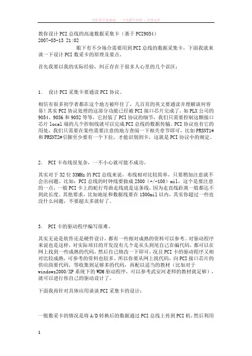
教你设计PCI总线的高速数据采集卡(基于PCI9054)2007-03-13 21:02眼下有不少场合需要用到PCI总线的数据采集卡,下面我就来谈一下设计PCI数采卡的原理及要点。
首先我要以我的实际经验,纠正存在于很多人心里的几个误区:1.设计PCI采集卡要通读PCI协议。
相信有很多初学者都在这个地方被吓住了,几百页的英文要通读并理解谈何容易!其实PCI协议处理的这部分功能已经被PCI接口芯片完成了,如PLX公司的9054、9056和9052等等,它封装了PCI协议的细节,我们只需要控制这颗接口芯片local端的几个控制线就可以完成PCI总线的数据传输。
PCI协议也有它的用处,我们只需要在某些需要注意的地方查阅一下相关章节即可,比如PRSNT1#和PRSNT2#引脚至少要有一个下拉,才能识别到卡,这就是PCI协议中的规定。
2. PCI卡布线很复杂,一不小心就可能不成功。
其实对于32位33MHz的PCI总线来说,布线相对比较简单,只要稍加注意就不会出问题。
比如:PCI总线的时钟线要做成2500(+/-100)mil,这个是要注意的一点,一般PCI卡上的蛇行弯曲走线就是这条线,因为走直线距离一般都达不到此长度。
其他要求,比如地址和数据线要在1500mil以内,其实你超过一些也没什么问题,不要超太多就好了。
3. PCI卡的驱动程序编写很难。
其实无论是软件还是硬件设计,都有一些相对成熟的资料可以参考。
对驱动程序来说也是这样,对实际项目的开发没有几个是从头到尾自己在编代码,都可以在网上找到一些成熟的代码,然后自己修改一下即可,况且PCI卡的驱动程序又相对比较成熟,可参考的资料也较多。
所以你要从网上找代码,向PCI接口芯片的供应商要代码,等收集到足够多的代码,再配以适当的教材(比如对于windows2000/XP系统下的WDM驱动程序,可以参考武安河老师的教材就足够),就可以进行你自己的驱动设计了。
下面我再针对具体应用谈谈PCI采集卡的设计:一般数采卡的情况是将A/D转换后的数据通过PCI总线上传到PCI机,然后利用上层的软件进行分析处理。
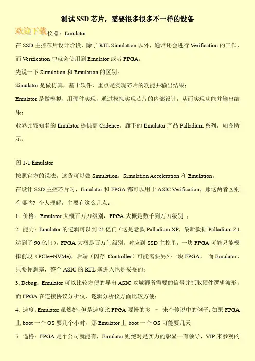
测试SSD芯片,需要很多很多不一样的设备仪器:Emulator在SSD主控芯片设计阶段,除了RTL Simulation以外,通常还会进行Verification的工作,而Verification中就会使用到Emulator或者FPGA。
先说一下Simulation和Emulation的区别:Simulator是做仿真,基于软件,重点是实现芯片的功能并输出结果;Emulator是做模拟,用硬件实现,通过模拟实现芯片的内部设计,从而实现功能并输出结果;业界比较知名的Emulator提供商Cadence,旗下的Emulator产品Palladium系列,如图所示。
图1-1 Emulator按照官方的说法,这货可以做Simulation,Simulation Acceleration和Emulation。
在设计SSD主控芯片时,Emulator和FPGA都可以用于ASIC Verification,那这两者区别有哪些? 个人理解,主要有这么几点:1. 价格:Emulator大概百万刀级别,FPGA大概是数千到万刀级别;2. 能力:Emulator的逻辑可以到23亿门(这是老款Palladium XP,最新款据Palladium Z1达到了90亿门),FPGA大概是百万门级别。
对应到SSD主控里,一块FPGA可能只能模拟前段(PCIe+NVMe),后端(闪存Controller)可能需要另外一块FPGA,而Emulator,只要你想塞,整个ASIC的RTL塞进入也是妥妥的;3. Debug:Emulator可以比较方便的导出ASIC攻城狮所需要的信号并抓取硬件逻辑波形,而FPGA在连接协议分析仪,逻辑分析仪方面比较方便;4. 速度:Emulator虽然好,但是速度比FPGA要慢的多–来个传说中的例子:如果FPGA 上boot一个OS要几个小时,那Emulator上boot一个OS可能要几天5. 逼格:FPGA是个公司就能有,Emulator则绝对是实力的彰显—有领导,VIP来参观的。

竭诚为您提供优质文档/双击可除pcie协议分析仪篇一:网络协议分析仪使用淮海工学院计算机工程学院实验报告书课程名:《tcp/ip与网络互联》题目:实验三网络协议分析仪使用班级:网络122学号:姓名:一、实验目的通过本次实验,熟悉Flukenetworks公司协议分析仪的使用,掌握opV软件的使用,掌握网上数据采集方法,并利用专家系统对其进行分析。
二、实验内容1、把Fluke协议分析仪正确接入网中。
2、在主机上执行opV软件。
3、设置捕获条件进行捕包。
4、利用专家系统对其进行分析。
三、实验步骤与源程序1.把Fluke协议分析仪正确接入网络中并启动;2.打开optiViewbrowser软件;3.进行捕包操作,并利用专家系统对icmp及tcp、udp 数据包进行分析;四、测试数据与实验结果1.首先在两台计算机上进行路由器配置,使用ping命令测试连通性2.、启动opV软件,其界面如图3-1所示。
3、设置过滤器,利用opV捕获Rip数据包,利用专家系统分析Rip数据包。
Rip数据包如图3-2所示。
02表示命令字段,表示响应报文;01表示版本号为1;00000002表示tcp/ip协议;c0a80100表示信宿网络的ip地址192.168.1.0;4.设置过滤器,捕获ip数据包,并启动捕获。
利用opV 捕获ip数据包,利用专家系统分析ip数据包。
46表示版本为0x46;00表示服务类型为0x00;0028表示数据包总长度为40byte;0011表示标识为17;0000表示片偏移为0x0000;0102分别表示生存时间与协议标识为1,2;08bc表示校验和为0x08bbc;3ac0012d表示原地址:58.92.1.45e0000016表示目的地址:224.0.0.22;5.设置过滤器,捕获aRp数据包,并启动捕获。
利用opV捕获aRp数据包,利用专家系统分析aRp数据包。
0010表示硬件类型为1;0800表示协议类型ipv4;0604表示硬件地址,协议地址长度分别为6,4;0001表示操作类型为1,表示aRp请求;c81F660ed462表示发送方硬件地址;c0a8030a表示发送方ip地址192.168.3.10;000000000000表示目的硬件地址;c0a80301表示目的ip地址192.168.3.16.设置过滤器,捕获icmp数据包,并启动捕获。
是德科技U4611A/B USB 2.0/3.0协议分析仪采用MegaZoom 技术的3.7.x 版本技术资料唯有是德科技能够提供深入、快速分析当前高性能超高速(SuperSpeed)USB 设计所必需的测试工具。
高性能分析–实时端点分析–实时链路分析–实时LTSSM–详细的性能记录–可定制的触发、计数、过滤即时访问捕获到的数据–分段存储器可更高效地保存多次事件捕获的结果–可捕获多达18 GB 的数据–直观的图形用户界面只需点击一下即可查看数据–面向规范的清晰数据解码概述Keysight U4611A/B USB 协议分析仪提供业界领先的实时性能分析、LTSSM 状态跟踪、最全面的触发系统以及高达18 GB 的可定制数据分析特性,从而将协议分析仪的易用性提升到更高水平。
是德科技提供的协议分析仪是在复杂超高速USB 系统中查找间歇性问题的最佳工具。
对于当今的USB 开发商和集成商来讲,要想确保他们设计的产品与日益增长的无数USB 设备完全兼容是几乎不可能的任务。
通常,捕获大批量流量会遇到很多困难,例如迹线缓冲区空间有限、查看数据时等待时间过长、搜索和保存速度太慢等。
随着USB 3.0 设计不再局限于基本功能,USB 设计人员正力求使新的和现有的USB 器件发挥最佳性能。
MegaZoom™ 技术可实时分析USB 操作,并提供详细的操作性能显示。
Keysight U4611A/B USB 协议分析仪能够即时显示捕获到的数据,甚至拥有高达18 GB 的数据轨迹捕获深度,从而克服了这些限制。
通过硬件加速千兆位以太网(高达70 MB/s)或PCI Express(高达550 MB/s)将轨迹数据传输到主机,无需等待即可分析完全深度数据。
例如,只需15 秒便可获得完整18 GB 轨迹的直方图。
数据可以显示为变址前(Pre-indexed)和压缩轨迹数据形式,可通过多个分析处理器进行分析。
图 1. U4611A/B 分析仪以直通模式连接,并记录主机与被测器件之间交换的流量。
pcie协议分析仪PCIe协议分析仪。
PCIe(Peripheral Component Interconnect Express)是一种用于连接外部设备的高速串行计算机扩展总线标准。
它是PCI总线的最新版本,旨在取代PCI和AGP标准。
PCIe协议分析仪是用于分析PCIe协议的工具,它可以帮助工程师深入了解和分析PCIe总线上的数据传输和通信过程。
PCIe协议分析仪的原理是通过捕获和分析PCIe总线上的数据流,从而实现对数据传输的监控和分析。
它可以帮助工程师识别和解决PCIe总线上的通信问题,提高系统的稳定性和可靠性。
PCIe协议分析仪通常包括硬件和软件两部分。
硬件部分包括捕获数据的PCIe探头和数据存储设备,软件部分包括用于分析和显示数据的分析软件。
通过硬件和软件的配合,PCIe协议分析仪可以实现对PCIe总线上数据的全面监控和分析。
PCIe协议分析仪的功能包括但不限于:1. 数据捕获,能够捕获PCIe总线上的数据流,包括命令、地址和数据等信息。
2. 数据分析,能够对捕获的数据进行解析和分析,识别数据传输过程中的问题和异常。
3. 时序分析,能够分析数据传输的时序特性,包括时钟、数据有效性和延迟等参数。
4. 事件触发,能够根据预设条件触发数据捕获,以便对特定事件进行分析和跟踪。
5. 协议验证,能够验证PCIe协议的遵从性,确保系统的兼容性和稳定性。
使用PCIe协议分析仪的好处包括但不限于:1. 故障排除,能够帮助工程师快速定位PCIe总线上的通信问题,缩短故障排除时间。
2. 性能优化,能够帮助工程师分析PCIe总线上的数据传输性能,优化系统的性能和效率。
3. 协议验证,能够验证系统对PCIe协议的遵从性,确保系统的兼容性和稳定性。
在实际应用中,工程师可以根据具体的需求选择合适的PCIe协议分析仪。
一般来说,选择PCIe协议分析仪时需要考虑以下几个方面:1. 数据捕获能力,包括数据传输速率、数据存储容量和数据捕获的灵活性。

逻辑分析仪和协议分析仪的区别――BJLK逻辑分析仪是通用的测试仪器,主要用于数字信号的时序和逻辑关系测量。
由于其可以提供很多测量通道,因此常用于并行总线测量。
一些高端的逻辑分析仪采用插卡式结构,单机箱最多可以配置6个测量模块,每个模块可以有68~102个测量通道,其模块最大状态采样率到2G/s,广泛应用于CPU/Memory/DSP/FPGA 等并行总线和数据的调试。
更进一步的,逻辑分析仪也可以通过扩展相应的软件对所抓取的数据进行更高级的分析,即从逻辑时序中解出其代表的数据包的具体含义。
如Agilent的逻辑分析仪可以选配B4621A的DDR2/3解码软件实现DDR2/3总线的解码和总线统计分析。
对于一些常用的高速串行总线,如PCIe/SATA等,由于其数据速率高达5Gbps,而且是内嵌时钟,逻辑分析仪的采样率和时钟模式都不太适合对这种总线直接采样,因此需要配合相应的分析探头(一台外置的测量模块)把高速的串行总线先解成较低速的并行总线,再连接逻辑分析仪进行采集和总线解码,从而实现相应的协议分析功能。
如Agilent的逻辑分析仪可以配合N4219B模块实现SATA/SAS的协议分析。
用逻辑分析仪做高速串行总线分析最大的一个障碍是基于数据包的触发功能比较有限,因为一个简单的数据包格式触发设置就可能耗掉逻辑分析仪的所有触发资源,因此很多和逻辑分析仪配合的分析探头如前面提到的做SATA分析的N4219B都内置了基于包的硬件触发功能。
而协议分析仪属于专用的测试仪器,主要用于特定总线的协议分析。
其内部一般内置相应的硬件解码模块,因此针对特定总线应用来说,其解码速度快、触发和分析功能强大,对于熟悉特定总线协议的工程师来说使用起来相对比较方便。
同时有些协议分析仪除了可以分析总线以外,还有训练器模块,即可以主动编辑产生符合相关协议的数据包与被测系统交互,更好地验证数据的交互过程。
如Agilent 的E2960B PCIE协议分析仪,可以提供X1~X16的PCIE GEN1/GEN2的协议分析,其可以设置30多种错误触发模式,同时提供PCIE的PTC模块(即进行一致性测试的训练器)和通用的训练器,可以帮助用户快速验证和发现协议的错误。

Our products are backed by over 125 years of experience in test and measurement equipment, and encompass the latest international standards for quality and safety.OscilloscopeOX 9000 SERIES4-in-1 InstrumentOscilloscope Multimeter AnalyzerLogger Safety•All channels isolated from one another and from the earth, 600V CAT IIIErgonomic•Modern, high tech design which is simple, compact and practicalOptimization•of all tools; communication, storage and operationisolated channelswith the recorded files directly viewable on screen2 Technical Assistance (800) 343-1391ERGONOMICSOriginalIn a housing tailor-made to be as compact as possible, the mechanical design makes it possible to integrate the hardware components in a small size with the keypad benefits from new technology developed inthe automotive industry.Scope in carrying case with shoulder strap, set of two 5 ft color-coded leads, alligator clips and test probes, 10 ft USB cable, µSD memory card, 1-PROBIX Banana Plug Adapter, 1 stylipen, LI-ION 5.8 Ah battery pack, PA40W-2 power adapter with 110V power cord. Additionalaccessories may be model dependent.Designed to simplify use with one button access to most functionsCHANNEL AND PARAMETER IDENTIFICATIONEach channel and related parameters are identified with identical color against a black background for simpler, quicker viewing.EASY ACCESS VIA TOUCH SCREENIntuitive icons are provided to facilitate their use, even with gloves on.ADJUSTABLE STRAPThis helps to optimize operation of the oscilloscope in your hand or on your shoulder when working in the field.A stand is also available to vary the orientation of the oscilloscope when it is placed on a bench. The oscilloscope can be safely left unattended using the Kensington locking system.NEW KEYPAD DESIGN FOR OPTIMUM USER COMFORTConfiguration and measurement displays are simple to access from the front panel in one of these 5 specific areas: Utilities (brightness, full screen, screenshot), Measurements, Vertical, Horizontal, Trigger.LINE POWER OR LI-ION BATTERYPort on left side.Technical Assistance (800) 343-1391 3APPLICATIONSElectronic maintenanceThe OX 9304 model is ideal for electronics with its300 MHz bandwidth, 4 x 600V CAT III isolated channels, advanced trigger functions, integrated FFT function,complex mathematical calculations on the curves, automatic measurements on 4 channels and the built-in WEB server.Industrial maintenanceThe OX 9304’s large 7-inch screen, 300 MHz bandwidth, 4 x 600V CAT III isolated channels and Harmonic Analyzer and Multimeter modes make it ideal for industrial maintenance applications.Ideal for electronic and industrial maintenanceIP54Housing protected against dust and water spray.DIRECT ACCESS ZOOM BUTTON7" WVGA WIDE COLOR TFT TOUCH SCREENMakes it easy to view and read the measurements clearly.It also provides a screen resolution of 800 x 480 dpi with manual or automatic brightness.TOUCH-SCREEN STYLUS STORAGEAmong the essential tools available, the sylus is equipped with a hook for the addition of a cord to make it captive, as required. One end is slightly flattened to prevent rolling when placed on a table or bench.COMMUNICATION INTERFACESThese are isolated from one another and from the measurement channels. A dedicated compartment on the right side protected by a flexible cover contains all the different communication interface ports:• USB host for communication with a PC• wired RJ45 or WiFi for communication with a PC or printing via a network printer• µSD card for data storage with quick transfer and forupgrading of the instrument's firmware AUTOSET BUTTONDIRECT SETTING AND SET-UP BUTTONS Quickly and effortlessly adjusts the horizontal and vertical; sensitivity and scales to provide the best resolution.Channels are isolated.4 Technical Assistance (800) 343-1391ACCESSORIESOSCILLOSCOPE OX 9000 SERIESThe plug and play accessories included areautomatically recognized when connected to the oscilloscope. They provide quick and easyimplementation with total user safety. Additionally, accessories equipped with BNC connectors orstandard banana plugs can also be connected when using the supplied adapter.Interchangeable ID Markers can be used on theaccessories plugged into a given channel to identify them with the trace color displayed on the screen.Additionally the 10:1 probe accessory is equipped with3 adjustable buttons to optimize its measurement capabilities.voltage measurements• by probe with different bandwidths and attenuation• by BNC or banana jack connection current measurements• by AC or AC/DC current clamp • directly through banana jack connections temperature measurements• using a K thermocouple sensor • using a PT100 RTD sensorAccessories & ReplacementsCat #2124.73 - PROBIX PRHX1 10:1 Probe, 250MHz 600V CAT III Cat #2124.77 - PROBIX Current Probe, 20mA-20A 1MHz-3dB Cat #5000.17 - Set of 5 styli pensOnce one of the provided standard accessories has been plugged in, it is automatically identified and itscharacteristics and calibration references are retrieved by the OX9000 Series Oscilloscope. All accessories are directly powered by the oscilloscope.Sensor coefficients scales and units of measure are managed automatically, as is channel configuration. Control buttons on the probes can be used to modify the settings of the channels to which they are connected. They also offer functions accessible on the oscilloscope's front panel.Accessories automatically recognized when connected to the oscilloscopeIdentification and Safety ManagementChannel Configuration and Sensor ManagementPROBE FUNCTIONSTechnical Assistance (800) 343-1391 5COMMUNICATIONChoice of communication interfaces―you can choose the type of communicaton to fit your requirements.Several communication choices are built into the OX9000 Series oscilloscope.• Wired Ethernet LAN network with integrated DHCP server for easy connection to your network• WiFi ® radio link to communicate with a PC, tablet or smartphone using the dedicated interfaces• USB for interfacing with the PC; record, recall or load configurations• µSD with >8 GB, default storage giving priority over the 1 GB internal memoryFile ManagementAny of the signal traces can be displayed instantaneously as the reference by pressing a single button which will obtain a comparison an immediate measurements of the deviation of ongoing measurements.Backups are available in various formats for direct export into a standard application such as Windows base spreadsheets or word processors.It is easy to take screenshots directly from the front panel and save them in a .PNG format, print documents on a network printer and transfer or delete files in the file manager.Data Processing• Use the oscilloscope screen to recall screenshots and stored traces for direct review on screen• On your PC, use the ScopeNet application in your web browser with either the USB or Ethernet connection for remote control and programming with SCPI commandsElectrical TroubleshootingEducationIn the laboratoryFor added equipment and operator safety all communication from theinstrument is totally isolated from the measurement process6 Technical Assistance (800) 343-1391Improved functions and performance levels of the OX9000 Series4 MODES: Oscilloscope, Multimeter, Analyzer, RecorderTrigger FunctionsAn oscilloscope with complex trigger functionsrecords what is necessary, while capturing all the faults The OX9000 models offer advanced triggers whichcomplement the main edge trigger options: pulse width, counting and delay.• The Delay mode enables you to observe any event with maximum resolution, even if it occurs a long time after effective triggering, or on two different channels.• The Counting mode enables you to count theevents before triggering, so that you can check the content of digital frames. For example, the trigger can be linked to a second “auxiliary” signal which is different from the “main” signal.Automatic MeasurementsComprehensive automatic measurements are displayed with cursors for precise analysis. The automaticmeasurements window displays all 20 parameters at the touch of a button for 4 channels. Two horizontal and vertical cursors can be used to view the section of the signal where the first automatic measurement was performed.A specific measurement area can then be selected by framing it with manual cursors for more accurate, reliable results.Direct comparison of two traces can be performed by checking the “reference memory deviation” box, so that these 20 signal parameters are displayed in terms of deviations.• wider bandwidth up to 300 MHz• new triggering and recording options • increased storage capacity, and more!• 12 bit resolution • 2.5 GS/secOSCILLOSCOPE:VIEW ALL 4 CHANNELS SIMULTANEOUSLY waveform + FFTwaveform + XY waveform + zoomThe Math FunctionsIn oscilloscope mode, the MATH functions (1, 2, 3 and 4) allow you to define a mathematical function for each of the traces, along with vertical scaling and labeling of the actual physical unit.The mathematical editor is capable of displaying 4 calculated traces on which all the automatic or cursor measurements remain available. This means it ispossible to examine the waveforms, such as the power (V x I), and perform all the associated measurements.A large number of operators are available, including +, -, x and / , as well as more complex operators such as sine, cosine, exponential, logarithm, square root, etc.opening the way for specific applications.Real-time Fast Fourier Transform (FFT) for frequency decomposition of your signals on 4 channelsThe FFT is used to calculate, from 2500 pointsupwards, the discrete representation of a signal in the frequency domain from its representation in the time domain. It is often particularly useful for arriving at an effective diagnosis during qualitative analysis of the signals:• measurement of the individual harmonics or distortion of a signal• analysis of a pulse response• search for the source of noise in the logic circuits Several weighting windows are available, as well as 2 representation modes: linear or logarithmic (scale in dB). The 2 cursors can then be used for precise measurements of the frequency lines, the levels and the attenuations, taking advantage of the 80 dB dynamic range allowed by the 12-bit / 2.5 GS/s conversion.The autoset button makes it easier to obtain anoptimum spectral representation to which a graphical zoom can be applied to analyze all the details of the spectrum.Technical Assistance (800) 343-1391 74 MODES: Oscilloscope, Multimeter, Analyzer, RecorderHarmonics4 Simultaneous ChannelsHarmonic AnalysisHarmonic analysis is performed on all 4 channels up to the 63rd order to comply with the requirements of the EN 50160 standard (THD on harmonics up to the 50th), with a fundamental frequency between 40 and 450 Hz.It is possible to preselect the frequency of the fundamental for the standards (50 Hz, 60 Hz and 400 Hz).This function helps to improve analytical performance and, above all, measurement when the level of a harmonic order is greater than the fundamental.It is possible to view the harmonic analyses of two or four channels simultaneously: RMS level, harmonic distortion, harmonic frequency, phase of the harmonic in relation to the fundamental.MultimeterBy simply selecting the dedicated icons, you can gain access to the multimeter mode without changing the measurement input channels. The OX9000 models offer an 8,000-count TRMS digital multimeter with two or four channels which can perform the following measurements:• amplitude (DC or AC voltage and current, power, temperature, etc.)• resistance, continuity, capacitance • component diode testsTemperature is measured using the Pt 100 and Pt 1000 sensors or K thermocouples via the dedicated PROBIXsensors. The power measurements are proposed as follows with choice of the configuration:• single-phase power• three-phase power on balanced network without neutral Measurement between H and V cursors:T1, T2, Dt, 1/Dt, V1, V2, dV, Ph• three-phase power on balanced network with neutral • 3-wire three-phase power (2-wattmeters method)Recorder/loggerThis is the mode for recording the trends in Multimeter mode. A genuine fast digital logger is provided inside the instrument to monitor the variations of physical or mechanical phenomena over time. It offers acquisition intervals as short as 40µs between 2 measurements and recording can cover any period from 2 seconds to one month.The four modes are directly accessed at the press of a button or touchscreen icon providing instant access the mode you needChauvin Arnoux ®, Inc. d.b.a AEMC ® Instruments • 15 Faraday Dr. • Dover, NH 03820 USA • (800) 343-1391 • (508) 698-2115 • Fax (508) 698-2118E-mail:**************| Export Department: +1 (603) 749-6434 x520 • Fax +1 (603) 740-7550 •E-mail:***************950.BR-OX9000Series_1021 • Printed in the USA© 2021 Chauvin Arnoux ®, Inc. d.b.a. AEMC® Instruments Call the AEMC ® Instruments Technical Assistance Hotline for immediate consultation with an applications engineer: (800) 343-1391 (Ext. 351)。
基于PCI9054的PCI接口板设计,电子商务- 基于PCI9054的PCI接口板设计简介谢冲,中国人民解放军驻六三一所代表室工程师,硕士。
主要从事计算机硬件设计。
董鹏举,西安邮电学院助理工程师。
主要从事自动化。
摘要:用PCI接口芯片实现的PCI总线接口板具有成本低,通用,设计难度低,开发周期短的优点,使用这种设计方法能够减少许多相应的外围器件,可用于开发各种高速数据采集系统、图象处理系统等PCI总线扩展板。
关键词:PCI总线;PCI接口芯片;PCI接口板《中国电子商务》杂志征稿详情点击:http://引言PCI总线是一种高性能局部总线,是为了满足外设间以及外设与主机间高速数据传输而提出来的。
采用PCI总线进行数据传输,可以解决原有的标准总线数据传输率低带来的瓶颈问题。
因此,基于PCI总线的扩展板越来越多地被应用于各种高速、大数据量的处理系统中。
PCI总线接口板的设计必须符合PCI总线规范定义的电气特性和时序要求。
目前,PCI总线接口开发一般采用两种方式:一是采用CPLD来实现接口电路。
这种设计方法的优点是使用比较灵活,设计人员可以根据自己的需要设计适合于特定功能的接口电路,而不必实现PCI总线的全部功能。
但由于PCI总线协议复杂,设计PCI控制接口难度较大,对于产品不大又有时限的工程项目来说,耗时长、成本高。
二是采用通用PCI接口芯片,例如PLX公司的PCI9054、PCI9050、PCI9080等,它们均实现了PCI 总线规范要求的所有硬件接口信号和配置空间寄存器。
相比于CPLD设计控制接口的设计方法,PCI接口芯片的成本较低,具有通用性,能够有效降低接口设计的难度,缩短开发时间。
1PCI接口芯片对于实现功能比较简单,成本要求较低的PCI总线扩展板,使用专用接口芯片是最优选择。
PCI9054是使用较为普遍的一种PCI接口芯片。
PCI9054是由美国PLX公司生产的先进的PCII/O加速器,它采用了先进的PLX数据管道结构技术,具有比较高的性价比,相比于PCI9080、PCI9050性能更优越。
MIPI D-PHY/C-PHY Pattern Generator (码型产生器) & Protocol Analyzer (协议分析仪)深圳市锐测电子科技有限公司目前是加拿大Introspect公司的MIPI D-PHY/C-PHY Pattern Generator (码型产生器) & Protocol Analyzer (协议分析仪) 在中国区的独家授权代理商。
SV3C Patter Generator (PG):可调节MIPI D-PHY/C-PHY的各种参数/码型,包含:电压幅值、时序、抖动以及MIPI alliance针对D-PHY/C-PHY所规范的符合性测试项目均可完成.同时支持多通道测试:一台设备能同时支持D-PHY 4 Lane或C-PHY 3 Trios测试;PG能直接编辑发送各种不同格式的图片用于接收机的测试;内建完整的D-PHY/C-PHY Rx CTS符合性测试脚本;......SV3C Protocol Analyzer (PA):Introsepct是目前全世界唯一能够同时支持MIPI D-PHY/C-PHY DSI 2/CSI的协议分析仪设备的厂商,透过DPHY/CPHY Protocol Analyzer可以对MIPI DSI/CSI协议沟通命令进行解析,分析仪能够完整的抓取MIPI介面上,所有命令及送图的内容,包含所有DSI/CSI 协议的封包和解译封包内容,能大大提升C/D-PHY产品问题的定位与debug效率, 亦可作为golden device去接收及验证贵司MIPI Tx的信号。
另外,Introspect公司不仅仅只有针对MIPI D-PHY/C-PHY的测试解决方案,还有支持DDR3/DDR4/DDR5, PCIe Tx/Rx测试等方案。
pcie协议分析仪工作原理PCIE协议分析仪工作原理一、双方的基本信息甲方:XXXXXXXX公司乙方:XXXXXXXX公司二、各方身份、权利、义务、履行方式、期限、违约责任1.甲方的身份、权利、义务、履行方式、期限甲方为协议分析仪的供应商,拥有该产品的所有权和知识产权。
甲方的权利为向乙方提供PCIE协议分析仪,并在乙方收到产品的30天内提供使用说明并为其提供技术支持。
甲方的义务为确保产品质量和技术服务的有效性。
甲方需按时履行提供的产品和服务。
2.乙方的身份、权利、义务、履行方式、期限、违约责任乙方为协议分析仪的使用方,拥有买卖合同的权利和义务。
乙方的权利为使用协议分析仪,并获得甲方提供的技术支持。
乙方的义务为在遵守中国的相关法律法规的前提下合法使用该产品和保证产品的正常使用。
乙方需按照约定的期限支付产品的合法购买费用。
乙方须对产品在使用过程中的损坏或丢失等负责,并承担相应的责任和赔偿金。
3.遵守中国的相关法律法规双方需遵守中国相关的法律法规,如《电子商务法》、《合同法》、《消费者权益保护法》等法律法规,确保双方的行为合法合规,保障双方合法权益。
4.权力和义务的明确双方应当对本协议中涉及的权利和义务做出明确规定,并确保双方权利和义务的公平合理、明确明白。
三、法律效力和可执行性1.本协议是合法、有效、具有可执行性的协议,如有任何争议应通过协商解决。
如协商不成的,双方均可依法向有管辖权的人民法院提起诉讼。
2.双方应认真履行本协议中的各项约定,任何一方不得擅自变更、违反本协议。
3.本协议签订后生效,并在甲方收到乙方支付款项后生效。
本协议的有效期为两年,双方同意在协议到期前进行续签,以确保双方权益。
四、其他1.本协议条款详细,适用范围广泛,约定的权利义务和责任等情形十分明确,双方在签订本合同时应当严格遵守各项约定,以确保合同的有效性和执行性。
2.本协议的任何修改应经双方协商一致并签订书面协议。
若未签订书面协议,不得视为本协议的任何修改及变更。
重磅发布|极简工业推出“数采严选”系列产品——从数据采集到数据应用数采严选是极简工业面向工业互联网设备数据采集提供的系列标准化产品,旨在解决目前制造业企业设备接口、网络协议不统一问题;解决数据从采集到数据挖掘应用问题;解决打通OT到IT的数据高效传输问题,帮助客户快速、极简实现设备数据互联互通,并且高效数据应用。
数采严选系列产品,凝聚了极简工业数十年的自动控制产品研发经验、数万台设备数据采集经验,具有支持通讯协议多、工具化、使用方便、即插即用、强大的边缘计算功能等特点,数据接口开放、友好,方便快捷对接各大工业互联网平台和数据采集软件。
数采严选系列产品主要包括:注塑机数据采集产品DKN系列机床数据采集产品CNC系列通用PLC数据采集产品π系列非标自动化设备数据采集产品EBOX系列仪器仪表数据采集产品mini-GW系列I/O数据采集产品ECS系列核心功能:三大核心功能数据采集、边缘计算、数据对接。
全量数据通讯接入,边缘计算应用数据挖掘、高效数据对接节省平台软件开销。
1、数据采集支持95%PLC通讯协议支持90%注塑机通讯协议支持85%机床通讯协议支持无接口老旧PLC通讯支持RS232、RS485、RS422、CAN、以太网通讯接口。
1)注塑机弘讯、科强、KEBA、盟立、东华、star、伊士通、宝捷信、台湾长新、发那科等。
2)机床发那科、西门子、三菱、兄弟、Hass、新代、广数等。
3)PLC/触摸屏西门子、三菱、欧姆龙、松下、AB、施耐德、触摸屏、国产PLC等。
4)仪器仪表电表、水表、气表、温控仪等。
5)非标协议自由通讯非标协议、自定义协议。
6)协议监听串口监听、网口监听。
7)I/O数字量点、模拟量4-20mA、0-10V、热电阻等。
2、边缘计算支持各种数据处理、数据类型转换支持实时时钟支持自动校时支持设备状态时间计算算法、支持稼动率、OEE算法支持梯形图编程、支持下发控制支持任意协议数据转换1)数据处理2)数据计算3)时间计算、效率计算4)下行控制、参数设置5)数据挖掘、特征数据提取6)数据汇聚7)任意协议相互转换3、数据对接支持上云通过云端API数据对接支持MQTT对接第三方云平台支持本地以太网网口数据对接支持本地RS485串口数据对接支持分频传输、数据汇聚、触发传输1)分频传输、触发传输2)本地以太网口Modbus-TCP3)本地串口Modbus-RTU4)极简工业API(2G/4G/5G/ADSL)5)MQTT(2G/4G/5G/ADSL)数采严选秉承“开放、友好、极简、稳定”的合作理念,为广大工业互联网平台、MES服务商、数据采集服务商、设备厂提供优质的产品和满意的服务。
创业实践训练论文论文题目 SIEVERS 900型TOC分析仪的验证院部工学院学号姓名指导教师课题完成场所论文工作时间: 2016 年 6 月至 2016 年 7 月SIEVERS 900型TOC分析仪的验证目录摘要 (1)前言 (2)第一章 TOC分析仪的简介 (3)1.1简述 (3)1.2 仪器装置 (3)1.3仪器运作的原理 (3)第二章 TOC分析仪的验证 (4)2.1材料 (4)2.2预确认 (6)2.3运行确认 (6)2.4性能确认 (8)2.5特异性 (10)2.6方法耐受性 (11)2.7结果 (11)第三章制药用水中总有机碳的测定 (12)3.1材料 (12)3.2方法与结果 (12)第四章结论 (14)参考文献 (15)实训心得 (16)致 (17)SIEVERS 900型TOC分析仪的验证摘要:通过预先确定的一系列检查、测试和记录,对Sievers 900型TOC分析仪进行再验证及该分析仪的检测方法。
根据厂商声明的性能,采用预确认、运行确认、性能确认的方法。
验证系统适用性的响应系数、准确度、精确度、相对回收率等以上重要指标与厂商提供的性能指标相符,证明运行确认与性能确认通过。
关键词:TOC;制药用水;确认;系统性实验Validation of SIEVERS 900 TOC AnalyzerAbstract:Objective through predetermined series of inspection, test and record for revalidation Sievers 900 TOC analyzer and measuring method of the analyzer. According to a statement from vendor performance, using the pre qualification and operational qualification and performance qualification method. The result preliminary confirmation through; The response coefficient of the system applicability, accuracy, precision and relatively more important indexes such as recovery of performance indicators are provided with the manufacturers of operational qualification and performance qualification.Key words:the TOC;Pharmaceutical water;Confirmation;Systemic experiment前言在我国《药品生产质量管理规》(GMP)里,验证定义为:“证明任何程序、生产过程、设备、物料、活动或系统确实能达到预期结果的有文件证明的一系列活动”。
PCI产品及信号管理解决方案
励纯
【期刊名称】《电视技术》
【年(卷),期】2004(000)010
【摘要】广电技术在飞速发展,而设计规范与操作规程的制定却远远跟不上实际需要,这对于机房设计工程师来说,未来所面临的挑战是极其严峻的。
【总页数】3页(P71-73)
【作者】励纯
【作者单位】珠海东部吉洛德宽带器材有限公司,技术部,广东,珠海,519015
【正文语种】中文
【中图分类】TN943.6
【相关文献】
1.IDT发布PCI EXPRESS解决方案系列产品 [J],
2.Quicklogic发布QuickPCI ESP家族新产品QuickPCI提供完美整合PCI控制器与可编程逻辑的全面可定制PCI接口产品 [J],
3.Alliance提供混合信号、存储器以及系统解决方案Alliance Semiconductor混合信号产品行销经理Mark Sherwood专访 [J], 郑凯雯
4.凌华科技推出高分辨率PCI规格的数字化仪系列产品PCI-9816、PCI-9826以及PCI-9846——凌华科技积极扩充高分辨率数字化仪产品线,PCI-9816/9826/9846系列提供高精度、低噪音及高动态范围性能 [J], 无
5.Pericom发布全新高速PCIe 3.0信号交换、信号质量及频率控制解决方案 [J],
因版权原因,仅展示原文概要,查看原文内容请购买。
泰克为PCI Express 3.0推出逻辑分析仪测试解决方案
佚名
【期刊名称】《国外电子测量技术》
【年(卷),期】2010()5
【摘要】泰克公司日前宣布,为下一代PCIe规范PCI Express3.0推出完善的测试解决方案,用一个工具涵盖协议层分析和物理层分析。
泰克最新推出的
TLA7SA16和TLA7SA08逻辑协议分析仪模块、总线支持软件和探头相结合,使得PCIe3.0开发人员能够以独有的方式查看系统行为的时间相关特点,从协议层分析开始一直到物理层,调试难检问题的根本原因。
【总页数】1页(P98-98)
【关键词】测试解决方案;逻辑分析仪;泰克公司;PCI;协议分析仪;Ie3.0;支持软件;时间相关
【正文语种】中文
【中图分类】TN929.533
【相关文献】
1.泰克为调试FB-DIMM提供新型逻辑分析仪解决方案——泰克将在英特尔开发人员论坛上演示为PCI Express Gen 2和FB-DIMM提供的示波器,可以测试最新的串行数据标准 [J],
2.泰克为PCI Express
3.0推出逻辑分析仪测试解决方案 [J],
3.泰克推出PCI Express 3.0逻辑分析仪测试方案 [J],
4.泰克推出业界完整、灵活的自动PCI Express 3.0 Tx、Rx测试套件全面的接收
器和发射器解决方案为集成电路、主机和板卡设计人员提供一站式PCIe 3.0测试与调试 [J],
5.泰克推出能完善PCI Express 2.0测试解决方案的最新型串行分析仪 [J],
因版权原因,仅展示原文概要,查看原文内容请购买。