SMP04采样保持器
- 格式:pdf
- 大小:277.26 KB
- 文档页数:15

华为光传输设备检修标准化作业指导书目次1 范围22 规范性引用文件23 术语和定义24 检修前准备24.1 准备工作安排24.2 劳动组织及人员要求24.2.1 劳动组织24.2.2 人员要求34.3 备品备件与材料34.4 工器具与仪器仪表94.5 技术资料114.6 安全设施布置图114.7 检修前设备设施状态114.8 风险分析与预防控制措施125 流程图125.1 检修组织流程图125.2 检修作业流程图126 检修程序与作业规范127 报告与记录248 绩效指标24前言本标准化作业指导书是为规范华为光传输设备检修标准化作业而制定的。
制定本标准化作业指导书的目的是指导华为光传输设备检修现场作业的全过程控制,体现对设备及人员行为的全过程管理,保证现场作业过程的安全和质量,优化作业方案,提高效率,降低成本。
华为光传输设备检修标准化作业指导书1 范围本标准化作业指导书规定了华为光传输设备检修标准化作业的检修前准备、检修作业流程图、检修程序与作业规范、风险分析与预防控制措施、报告与记录、绩效指标等内容。
本标准化作业指导书适用于华为光传输设备检修标准化作业。
2 规范性引用文件下列文件对于本文件的应用是必不可少的。
凡是注日期的引用文件,仅所注日期的版本适用于本文件。
凡是不注日期的引用文件,其最新版本〔包括所有的修改单适用于本文件。
DL/T 547-2012 电力系统光纤通信运行管理规程Q/GDW 721-2012 电力通信现场标准化作业规范3 术语和定义下列术语和定义适用于本标准化作业指导书。
3.1通信检修作业通信检修作业是指对通信线路、通信设备、通信电源、网络管理系统等进行检查、检修及数据配置,需要进行设备硬件操作和数据配置操作,通常会改变设备、网络运行状态。
4 检修前准备4.1 准备工作安排根据工作安排合理开展准备工作,见表1。
表1 准备工作安排4.2 劳动组织及人员要求劳动组织明确了工作所需人员类别、人员职责和作业人员数量,见表2。


采样保持器各IC型号序号IC型号描述1ad1154Low Cost, 16-Bit Accurate Sample-and-Hold Amplifier 2ad1154ad$StartFalse3ad1154aw Sample/Track-and-Hold Amplifier4ad1154bd$StartFalse5ad1154bw Sample/Track-and-Hold Amplifier6ad386bd$StartFalse7ad386td Sample/Track-and-Hold Amplifier8ad386td/883b$StartFalse9ad582kd Sample/Track-and-Hold Amplifier10ad582kh$StartFalse11ad582sd Sample/Track-and-Hold Amplifier12ad582sd/883b$StartFalse13ad582sh Sample/Track-and-Hold Amplifier14ad582sh/883b$StartFalse15ad583kd Sample/Track-and-Hold Amplifier16ad585achips$StartFalse17ad585aq/+Sample/Track-and-Hold Amplifier18ad585schips$StartFalse19ad585se/883b Sample/Track-and-Hold Amplifier20ad585sq/883b$StartFalse21ad681aq Sample/Track-and-Hold Amplifier22ad681sq$StartFalse23ad682an Sample/Track-and-Hold Amplifier24ad682jn$StartFalse25ad682sq Sample/Track-and-Hold Amplifier26ad683aq$StartFalse27ad683sq Sample/Track-and-Hold Amplifier28ad684sq/883b$StartFalse29ad783an Sample/Track-and-Hold Amplifier30ad783jn$StartFalse31ad783sq Sample/Track-and-Hold Amplifier32ad783sq/883b$StartFalse33ad9100Ultrahigh Speed Monolithic Track-and-Hold 34ad9100*$StartFalse35ad9100ad Ultrahigh Speed Monolithic Track-and-Hold 36ad9100jd$StartFalse37ad9100sd Ultrahigh Speed Monolithic Track-and-Hold 38ad9100se/883b$StartFalse39ad9101125 MSPS Monolithic Sampling Amplifier40ad9101ae$StartFalse41ad9101ar125 MSPS Monolithic Sampling Amplifier 42ad9101se$StartFalse43adh-050Sample/Track-and-Hold Amplifier44adh-050-883b$StartFalse45adh-051Sample/Track-and-Hold Amplifier46adh-051-883b$StartFalse47ah20016Sample/Track-and-Hold Amplifier48ah201-1$StartFalse49ah201-2Sample/Track-and-Hold Amplifier50al1210ar$StartFalse51al1210-die Sample/Track-and-Hold Amplifier52al1210es$StartFalse53al1210jr Sample/Track-and-Hold Amplifier54al1210se$StartFalse55al1210sj Sample/Track-and-Hold Amplifier56cds-1401mc$StartFalse57cds-1401mm Sample/Track-and-Hold Amplifier59cs3101-kd Sample/Track-and-Hold Amplifier60cs3101-td$StartFalse61cs3112-bd1Sample/Track-and-Hold Amplifier62cs3112-kd1$StartFalse63cs3112-kd2Sample/Track-and-Hold Amplifier64cs3112-td1$StartFalse65cs31412-bc1Sample/Track-and-Hold Amplifier66cs31412-bd$StartFalse67cs31412-kc1Sample/Track-and-Hold Amplifier68cs31412-kc2$StartFalse69cs31412-kd Sample/Track-and-Hold Amplifier70cs31412-tc1$StartFalse71cs31412-td Sample/Track-and-Hold Amplifier72dgl-13-1$StartFalse73dgl-13-1-883b Sample/Track-and-Hold Amplifier74dgl-13-3$StartFalse75dgl-13-3-883b Sample/Track-and-Hold Amplifier76ha1-2420-2$StartFalse77ha1-2425-5 3.2レs Sample and Hold Amplifiers78ha1-5320-2$StartFalse79ha1-5320-5 1 Microsecond Precision Sample and Hold Amplifier 80ha1-5330-2$StartFalse81ha1-5330-5650ns Precision Sample and Hold Amplifier82ha-2420$StartFalse83ha-2425 3.2レs Sample and Hold Amplifiers84ha3-2425-5$StartFalse85ha3-5320-5 1 Microsecond Precision Sample and Hold Amplifier 86ha3-5330-5$StartFalse87ha4p2425-5 3.2レs Sample and Hold Amplifiers89ha-5330650ns Precision Sample and Hold Amplifier90ha9p2425-5$StartFalse91ha9p5320-5 1 Microsecond Precision Sample and Hold Amplifier 92ha9p5320-9$StartFalse93hs346b Sample/Track-and-Hold Amplifier94hs346c$StartFalse95hs9704b Sample/Track-and-Hold Amplifier96hs9704c$StartFalse97hs9705b Sample/Track-and-Hold Amplifier98hs9705c$StartFalse99hs9714k Sample/Track-and-Hold Amplifier100hs9714tb$StartFalse101hs9716k Sample/Track-and-Hold Amplifier102hs9716tb$StartFalse103hs9720k Sample/Track-and-Hold Amplifier104hs9720tb$StartFalse105htc-0300a Ultrahigh-Speed Hybrid Track-and-Hold Amplifiers106htc-0300am$StartFalse107htc-0300am/883b Ultrahigh-Speed Hybrid Track-and-Hold Amplifiers108htc-0300atd/883b$StartFalse109htc-0500am Sample/Track-and-Hold Amplifier110htc-0500sm$StartFalse111hts-0010Ultra High Speed Hybird Track-and Hold Amplifiers112hts-0010kd$StartFalse113hts-0010sd Ultra High Speed Hybird Track-and Hold Amplifiers115hts-0025m Ultra High Speed Hybird Track-and Hold Amplifiers116hv257$StartFalse117hv257fg32 CHANNEL HIGH VOLTAGE SAMPLE AND HOLD AMPLIFIER ARRAY 118hv257x$StartFalse119lf198MONOLITHIC SAMPLE AND HOLD CIRCUITS120lf198/bgc$StartFalse121lf198a Precision Sample and Hold Amplifier122lf198ah Monolithic Sample-and-Hold Circuits123lf198al Sample/Track-and-Hold Amplifier124lf198fe$StartFalse125lf198h Monolithic Sample-and-Hold Circuits126lf198h/883Monolithic Sample-and-Hold Circuits127lf198l$StartFalse128lf298MONOLITHIC SAMPLE AND HOLD CIRCUITS129lf298fe Sample-and-hold amplifiers130lf298h$StartFalse131lf298hb Sample/Track-and-Hold Amplifier132lf298m$StartFalse133lf298n Sample-and-hold amplifiers134lf398$StartFalse135lf398a$StartFalse136lf398ah$StartFalse137lf398ah/a+$StartFalse138lf398al Sample/Track-and-Hold Amplifier139lf398an$StartFalse140lf398an/a+Sample/Track-and-Hold Amplifier141lf398an/b+$StartFalse142lf398an8Precision Sample and Hold Amplifier143lf398d$StartFalse144lf398d-t Sample/Track-and-Hold Amplifier145lf398fe$StartFalse146lf398h Monolithic Sample-and-Hold Circuits 147lf398h/a+Sample/Track-and-Hold Amplifier148lf398hb$StartFalse149lf398jg Sample/Track-and-Hold Amplifier150lf398l$StartFalse151lf398m Monolithic Sample-and-Hold Circuits 152lf398mx$StartFalse153lf398n MONOLITHIC SAMPLE AND HOLD CIRCUITS 154lf398n/a+Sample/Track-and-Hold Amplifier155lf398n/b+$StartFalse156lf398n8Precision Sample and Hold Amplifier 157lf398nb$StartFalse158lf398p Sample/Track-and-Hold Amplifier159lf398s8$StartFalse160lf39j8Precision Sample and Hold Amplifier 161lf6197$StartFalse162lf6197ccj$StartFalse163lf6197j$StartFalse164lh0053g-mil Sample/Track-and-Hold Amplifier165max5165$StartFalse166max5165lccm 32-Channel Sample/Hold Amplifier with a Single Multiplexed Input167max5165lecm$StartFalse168max5165mccm 32-Channel Sample/Hold Amplifier with a Single Multiplexed Input169max5165mecm$StartFalse170max5165nccm 32-Channel Sample/Hold Amplifier with aSingle Multiplexed Input171max5165necm$StartFalse172max516632-Channel Sample/Hold Amplifier with Four Multiplexed Inputs173max5166lccm$StartFalse174max5166lecm 32-Channel Sample/Hold Amplifier with Four Multiplexed Inputs175max5166mccm$StartFalse176max5166mecm 32-Channel Sample/Hold Amplifier with Four Multiplexed Inputs177max5166nccm$StartFalse178max5166necm 32-Channel Sample/Hold Amplifier with Four Multiplexed Inputs179max5167lccm$StartFalse180max5167lecm SAMPLE/TRACK-AND-HOLD AMPLIFIER|32-CHANNEL|BICMOS|QFP|48PIN|PLASTIC 181max5167mccm$StartFalse182max5167mecm SAMPLE/TRACK-AND-HOLD AMPLIFIER|32-CHANNEL|BICMOS|QFP|48PIN|PLASTIC 183max5167nccm$StartFalse184max5167necm SAMPLE/TRACK-AND-HOLD AMPLIFIER|32-CHANNEL|BICMOS|QFP|48PIN|PLASTIC 185max5168$StartFalse186max5168lccm SAMPLE/TRACK-AND-HOLD AMPLIFIER|32-CHANNEL|BICMOS|QFP|48PIN|PLASTIC 187max5168lecm$StartFalse188max5168mccm SAMPLE/TRACK-AND-HOLD AMPLIFIER|32-CHANNEL|BICMOS|QFP|48PIN|PLASTIC 189max5168mecm$StartFalse190max5168nccm SAMPLE/TRACK-AND-HOLDAMPLIFIER|32-CHANNEL|BICMOS|QFP|48PIN|PLASTIC 191max5168necm$StartFalse192ne5537Sample-and-hold amplifier193ne5537d$StartFalse194ne5537n Sample-and-hold amplifier195se5537$StartFalse196se5537fe Sample-and-hold amplifier197vn1025cc$StartFalse198vn1025ci Sample/Track-and-Hold Amplifier 199vn1025cm$StartFalse200vn1025dc Sample/Track-and-Hold Amplifier 201vn1025di$StartFalse202vn1025dm Sample/Track-and-Hold Amplifier 203vn1025mc$StartFalse204vn1025mi Sample/Track-and-Hold Amplifier 205vn1025mm$StartFalse206vn1025sc Sample/Track-and-Hold Amplifier 207vn1225cc$StartFalse208vn1225ci Sample/Track-and-Hold Amplifier 209vn1225cm$StartFalse210vn1225dc Sample/Track-and-Hold Amplifier 211vn1225di$StartFalse212vn1225dm Sample/Track-and-Hold Amplifier 213vn1225sc$StartFalse厂家Analog DevicesAnalog Devices Analog Devices Analog Devices Analog Devices Analog DevicesIntersil CorporationIntersil CorporationIntersil Corporation Intersil CorporationIntersil Corporation Intersil CorporationIntersil Corporation Intersil CorporationAnalog Devices Analog DevicesAnalog Devices Analog Devices Analog Devices Supertex, Inc ETCLinear Technology National Semiconductor National Semiconductor National SemiconductorETCPhilips Semiconductors Philips SemiconductorsLinear Technology National SemiconductorNational Semiconductor ETCLinear Technology Linear Technology Maxim IntegratedProductsMaxim Integrated ProductsMaxim Integrated ProductsMaxim Integrated ProductsMaxim Integrated ProductsMaxim Integrated ProductsMaxim Integrated ProductsMaxim Integrated ProductsMaxim Integrated ProductsMaxim Integrated ProductsMaxim Integrated ProductsMaxim Integrated ProductsMaxim Integrated ProductsPhilips SemiconductorsPhilips SemiconductorsPhilips Semiconductors。

取样探头222.15/17/20/21/31/35安装及使用说明书BC460017, 07/2017 Art. Nr. 90 31 059Bühler Technologies GmbH, Harkortstr. 29, D-40880 RatingenTel. +49 (0) 21 02 / 49 89-0, Fax. +49 (0) 21 02 / 49 89-20AP000005请在安装和使用前仔细阅读此手册。
敬请特别注意所有安全守则,以避免不必要的意外伤害事故。
Bühler Technologies GmbH /德国比勒科技有限责任公司对由不当操作以及在未授权情况下擅自改动机器设备所引起的后果不承担任何责任。
目录页1概述 (4)2重要注意事项 (4)2.1安全注意事项概述 (5)3铭片说明 (6)4产品说明 (6)4.1概述 (6)4.2发货内容 (6)5运输及存储要求 (7)6安装及线路连接 (7)6.1安装 (7)6.2探管的连接 (8)6.2.1样气管的连接 (9)6.2.2校正气体管的连接(可选) (9)6.3反吹和反吹气罐的连接(适用于 GAS 222.21, 31 和 35) (9)6.4电子线路连接 (10)6.4.1型号 GAS 222.15 / GAS 222.17 (10)6.4.2型号 GAS 222.20, 21, 31, 35 (10)6.4.3加热反吹气罐(可选) (11)6.4.4加热扩展件(可选) (11)7操作与维护 (11)7.1安全条款 (11)7.2操作前请检查 (12)7.3探头GAS 222.20, 21, 31, 35 上控制器的功能 (13)7.3.1所有控制器的功能 (13)7.3.2加热扩展件的内置控制器的更多功能(可选) (13)7.3.3内置反吹控制器的功能 (13)7.3.4附加PCB电路板用于电磁阀和限位开关(可选电磁阀控制板) (13)7.4滤芯的维护: (13)7.4.1带顺流过滤器的探头GAS 222.15 (13)7.4.2使用玻璃纤维滤芯的顺流过滤器 (14)7.4.3带顺流过滤器的探头GAS 222.17, 20 和 21 (14)7.4.4带直插过滤器的探头GAS 222.21, 31 和 35 (15)7.5工艺管道中直插过滤器的反吹 (16)7.5.1手动反吹 (16)7.5.2自动反吹 (16)7.5.3内置反吹控制器 (17)7.6控制器的设置 (18)7.6.1菜单选项 (18)7.6.2操作原则详述 (19)7.6.3菜单功能说明 (20)7.6.3.1主菜单 (20)7.6.3.2探头控制器的子菜单(Display: Prob) (21)7.6.3.3加热扩展件控制器的主菜单(display: Adon) (可选) (21)7.6.3.4反吹控制器的子菜单(display: bbc) (可选) (22)8故障及故障排除 (23)8.1备件 (24)9维修及报废处理 (24)9.1报废处理 (24)10制图,证明,数据表 (25)10.1接线图 GAS 222.15/17 (25)10.2接线图 GAS 222.20, 21, 31, 35 (26)10.3加热气罐的连线图 (27)10.4附加文件 (27)1 概述GAS 222.xx系列探头设计安装于气体分析系统内部。
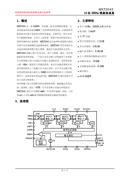
采样保持器采样保持器计算机系统模拟量输入通道中的一种模拟量存储装置。
它是连接采样器和模数转换器的中间环节。
采样器是一种开关电路或装置,它在固定时间点上取出被处理信号的值。
采样保持器则把这个信号值放大后存储起来,保持一段时间,以供模数转换器转换,直到下一个采样时间再取出一个模拟信号值来代替原来的值。
在模数转换器工作期间采样保持器一直保持着转换开始时的输入值,因而能抑制由放大器干扰带来的转换噪声,降低模数转换器的孔径时间,提高模数转换器的精确度和消除转换时间的不准确性。
一般生产过程控制计算机的模拟量输入可能是每秒几十点、几百点,对于大型系统甚至上千点,往往需要高速采样(如5000~10000点/秒)。
为使这些模拟量信号逐个地送到模数转换器,而不至降低被测信号的真实性,必须采用采样保持器。
在低速系统中一般可以省略这种装置。
原理采样保持电路由模拟开关、存储元件和缓冲放大器A组成。
在采样时刻,加到模拟开关上的数字信号为低电平,此时模拟开关被接通,使存储元件(通常是电容器)两端的电压UB随被采样信号UA变化。
当采样间隔终止时,D变为高电平,模拟开关断开,UB则保持在断开瞬间的值不变。
缓冲放大器的作用是放大采样信号,它在电路中的连接方式有两种基本类型:一种是将信号先放大再存储,另一是先存储再放大。
对理想的采样保持电路,要求开关没有偏移并能随控制信号快速动作,断开的阻抗要无限大,同时还要求存储元件的电压能无延迟地跟踪模拟信号的电压,并可在任意长的时间内保持数值不变。
光栅的组成结构和检测原理光栅是一种在透明玻璃上或金属的反光平面上刻上平行、等距的密集刻线,制成的光学元件。
数控机床上用的光栅尺,是利用两个光栅相互重叠时形成的莫尔条纹现象,制成的光电式位移测量装置。
按制造工艺不同可分为透射光栅和反射光栅。
透射光栅是在透明的玻璃表面刻上间隔相等的不透明的线纹制成的,线纹密度可达到每毫米100条以上;反射光栅一般是在金属的反光平面上刻上平行、等距的密集刻线,利用反射光进行测量,其刻线密度一般为每毫米4~50条。
PCL431Current CalibratorOperator’s ManualM1889/0994GENERAL DESCRIPTIONThe OMEGA®PCL431 Hand-Held Current Calibrator is designed to be a complete 4-20mA loop calibrator delivering high accuracy in a small, easy to use package. Its microprocessor based circuitry gives the usera large number of input/output options and operating modes without unnecessary complexity.Current can be sourced into loads up to 1000 ohms or simulated with external power supplies of up to60VDC. When operated in the read mode the user can input a current from a signal source directly, or in the read/power mode the PCL431 will supply 24 volt loop power to a two wire device and simultaneously monitor the resultant loop current. Both read and source measurements can be displayed directly inmilliamps or as a percentage of a 4-20mA loop.Commonly used outputs (up to 3) can be stored in the PCL431’s non-volatile memory for quick recall. In addition, an auto-step mode allows the calibrator to step through the selected setpoints at a user defined dwell time of 5 to 60 seconds.INSTALLATIONUNPACKINGRemove the Packing List and verify that all equipment has been received. If you have any questions about the shipment, please call the OMEGA Customer Service Department at 1-800-622-2378 or (203) 359-1660.When you receive the shipment, inspect the container and equipment for any signs of damage. Note any evidence of rough handling in transit. Immediately report any damage to the shipping agent.NOTE:The carrier will not honor any claims unless all shipping material is saved for theirexamination. After examining and removing contents, save packing material and carton in theevent reshipment is necessary.Check to see if your calibrator kit is complete - it should include:1. Carrying case (Qty=1)2. T est leads (Qty=1 set)3. 9V battery (Installed)4. Operator’s Manual (Qty=1)SET-UPBefore beginning, become familiar with the keypad layout and the configuration of the input/output jacks.Remember, these jacks are used in multiple configurations so pay careful attention to how the test leads are connected for the specific application.CJS0994RAF2BAOPERATING PROCEDURE1. Turn on power and select the desired range by depressing the ”RANGE SELECT” key.NOTE: When operating in the “%” range, 4mA=0% and 20mA=100%.2. Connections are made as follows:Current Source - Use jacks 1 and 2 (1 is +).Current Simulate - Use jacks 2 and 3 (2 is +).Current Read - Use jacks 3 and 4 (4 is +).Current Read/Power - Use jacks 1 and 4 (1 is +).3. The and keys adjust the output value up or down. Holding the ramp keys continuously forseveral seconds will increase the scroll rate. Going beyond the endpoints (0 and 24mA) will cause theoutput to wrap around, thus allowing a quick return to either end of the scale.4. Three calibration points can be stored in non-volatile memory by scrolling to the desired output,depressing the Store key, and then the desired setpoint key.5. The auto step will automatically step through the stored setpoints at pre-defined intervals. When theauto-step key is first depressed, the display will indicate the dwell time (in seconds) between steps.The factory set value is 15 seconds but you can set this value, from 5 to 60 seconds, by usingthe and keys when the dwell time is being displayed. Once you have scrolled to the desireddwell time, release the or key and wait approximately 3 seconds until the calibrator begins toautomatically step through the 3 setpoints. The calibrator will continue the stepping process until anykey is pressed. Your chosen dwell time will remain in a non-volatile memory location until you chooseto change it.OPERATING CONSIDERATIONS AND PRECAUTIONS1. When operating in the current source mode, the PCL431 has the capability to drive loads up to 1000ohms as shown in Figure 1.Figure 1 - Current Source Mode2. When operating in the current simulate mode, the PCL431 acts like a two-wire transmitter controlling acurrent loop with an external voltage of up to 60 VDC as shown in Figure 2.Figure 2 - Current Simulate Mode3. When reading a current loop, the PCL431 can measure over a range of 0-24mA. Connections areshown in Figure 3.Figure 3 - Current Loop Readings4. The PCL431 can simultaneously power a device with 24 volts and display the current flowing throughthe loop. This is particularly useful when calibrating a two-wire transmitter. A typical application isshown in Figure 4.Figure 4 - PCL431 Simultaneous Power/DisplayACCURACYThe PCL431 is checked against an NIST traceable reference before shipment to verify that each range falls within the 0.05%, ±1 count, of full scale accuracy specification. Long term accuracy should remain within0.1%, ±1 count, of FSR. All of these ratings are based on a 25°C ambient temperature. A change of 10°Cwill cause approximately a 1000 ppm change (based on 100 ppm/C temp.) in the output or the equivalent of a 0.1% output change. Therefore, allowances must be made for error caused by wide temperaturevariations.。
P O S I T A L编码器说明书 Prepared on 24 November 2020POSITAL编码器资料FRABA 编码器德国博思特POSITAL编码器、POSITAL工业编码器、POSITAL倾角仪,POSITAL传感器、POSITAL线性传感器,POSITAL绝对值编码器、POSITAL旋转编码器等。
编码器行业领导者上海精芬德国博思特POSITAL编码器、POSITAL工业编码器、POSITAL倾角仪,POSITAL 传感器、POSITAL线性传感器,POSITAL绝对值编码器、POSITAL旋转编码器等,如需询价或详细信息,方案选型与精芬联系。
德国POSITAL公司成立于1918年,致力于高端机电产品的研发及生产,是欧洲绝对值编码器产品的领跑者。
该公司产品广泛应用于冶金、汽车制造、水利、物流、机械制造、木材加工、造船等行业。
以下021列举部分型号:OCD-S200G-1412-B15S-PRL、OCD-S200G-1212-B150-PRL、OCD-S200G-1212-B15S-CRW、OCD-S200G-1213-B150-CAW、OCD-S200B-1213-SA1C-CRS-150、OCD-S200G-1416-S060-PRL、OCD-S200G-1213-B15C-CAS-182、OCD-S200G-1416-S100-CAW、OCD-S200G-1212-C100-PRL、OCD-S200G-1412-B150-PRL、OCD-S100G-1212-B150-PAL、OCD-S100G-0012-C100-PRL、OCD-S100G-1212-C10S-CRW-5m、OCD-S100G-1212-S100-PRL、OCD-S100G-1212-B15V-CAW-5m、OCD-S100G-0013-S100-PRL、OCD-S100G-1212-S10S-PRL、OCD-S100G-0016-S10S-PAL、OCD-S100B-1212-C10S-PRL、OCD-S100G-1416-C100-PRL、OCD-S100G-1213-C100-PA9、OCD-S100G-1213-C100-PAL、OCD-S100G-1212-S060-PRL-050、OCD-S100G-1212-B150-PRL、OCD-S100G-1213-C100-PRL、OCD-S100B-0016-B15S-CRW-136、OCD-S100G-1212-C100-PRL、OCD-S100G-1212-C100-CRW、OCD-S100G-1212-S060-PAL、OCD-S100B-0016-S060-PAL-135、OCD-S100G-0013-C100-PAL OCD-S100G-1213-T120-PRL、OCD-S100B-1212-S060-CRW、OCD-S100G-0016-T12C-CRW-163、OCD-S100G-1416-C10V-CAW-5m、OCD-S100G-1216-S10S-PRL、OCD-S100G-0016-T120-CRW、OCD-S100B-1212-C100-PRL、OCD-S100B-1212-B15V-CAW-5m、OCD-S100G-1212-B15S-PAL、OCD-S100B-0016-C100-CAW-5m、OCD-S100G-1212-C10S-PRL、OCD-S100B-0016-T120-CRW、OCD-S100G-1213-S10S-PRL、OCD-S100B-1213-C10S-PRL、OCD-S100G-0013-S060-PRL、OCD-S100B-0016-T120-PRL、OCD-SL00G-1213-SA1C-CRS-159、OCD-S100B-0016-B150-CRW、OCD-S100G-1212-S10V-PAL、OCD-S100B-0012-C100-PAL、OCD-S100G-1212-S100-CRW-10m、OCD-S100G-1212-B15S-PRL、OCD-S100B-1416-C100-CRW、OCD-S100G-1212-S060-CRW、OCD-S100B-12AJ-C10C-PRL-204、OCD-S100G-1213-S060-PAL、OCD-S100G-0013-C10C-PRL-050、OCD-S100B-1212-B15S-CRW-5m、OCD-S100G-1212-T120-PRL、OCD-S100G-0016-C10S-PRL、OCD-S100G-1213-S060-PRL、OCD-S100G-1213-B150-PRL、OCD-S100G-1213-C10C-PRL-050、OCD-S100G-1408-S10V-PAL、OCD-S100B-1212-B15S-CRW-10m、OCD-S100B-0013-S060-PAL、OCD-S100G-1213-B15S-PRL、OCD-S100G-1216-C10S-PRL、OCD-S100B-1416-B150-PRL、OCD-S100B-0016-S060-CAW、OCD-S100G-1212-S060-PRL、OCD-S100G-1212-C100-PAL、OCD-S100G-0013-C100-PRL、OCD-S100B-1213-B15V-PRL、OCD-S100B-0016-S060-PAL、OCD-SS00G-1412-C10S-PRL、OCD-SS00G-1212-C10S-PRL、OCD-SS00G-1212-C100-PRL、OCD-SS00G-1212-C100-CRB、OCD-SS00G-1212-C066-PA5、OCD-SS00G-1212-S06C-CRW-148、OCD-SS00G-0812-C106-PAL、OCD-SS00E-00AB-C066-PAB、OCD-SS00G-1212-C100-PR5、OCD-SS00G-0012-C106-PAB、OCD-SS00G-0412-C066-PRL、OCD-SS00G-0412-C066-PR5、OCD-SS00G-1212-C100-PAB、OCD-SS00G-0012-S06S-PRL、OCD-SS00G-0812-C066-PR5、OCD-SL00G-1212-C10V-CAW、OCD-SL00G-1213-S060-PAL-023、OCD-SL00G-1212-C10S-PAL、OCD-SL00G-0013-S060-CRS-010、OCD-SL00G-0812-C100-CRW、OCD-SL00B-0012-C100-PAL、OCD-SL00G-1212-C100-CRW-5m、OCD-SL00G-0016-C10S-CRW-097、OCD-SL00G-1213-SA5C-CRO-066、OCD-SL00G-1416-C100-PRL、OCD-SL00G-1214-C100-PRL-099、OCD-SL00G-0016-S06S-CAW-052、OCD-SL00B-1212-C100-PAL-050、OCD-SL00G-1212-S100-PRL、OCD-SL00B-0013-B150-PRL、OCD-SL00G-1212-B15S-PRL、OCD-SL00G-1412-C100-PRL-B、OCD-SL00G-0013-C100-PRB、OCD-SL00G-1213-C100-PRL-099、OCD-SL00G-0016-C100-CAW、OCD-SL00G-1213-C10S-CRW-2M、OCD-SL00B-0013-SB10-PAL、OCD-SL00G-1212-S06S-PRL、OCD-SL00G-1212-C100-PRB、OCD-SL00B-0012-C100-PAL-050、OCD-SL00G-1213-S060-CRW、OCD-SL00B-0014-B150-CRW-2m、OCD-S101G-1212-C100-CRW-2、OCD-S101G-1213-C100-CRW-2m旗下品牌BEN选型BEN是专业生产编码器的跨国公司,主要产品有绝对值编码器,增量和防爆编码器,BEN编码器总部在德国柏林,公司在欧洲、美洲和亚洲设有许多分支机构和代表处,是真正的国际性企业。
REV. DInformation furnished by Analog Devices is believed to be accurate and reliable. However, no responsibility is assumed by Analog Devices for its use, nor for any infringements of patents or other rights of third parties which may result from its use. No license is granted by implication or otherwise under any patent or patent rights of Analog Devices.aCMOS QuadSample-and-Hold AmplifierFUNCTIONAL BLOCK DIAGRAMFEATURESFour Independent Sample-and-Holds Internal Hold Capacitors High Accuracy: 12 BitVery Low Droop Rate: 2 mV/s typ Output Buffers Stable for C L ≤ 500 pF TTL/CMOS Compatible Logic Inputs Single or Dual Supply Applications Monolithic Low Power CMOS Design APPLICATIONSSignal Processing SystemsMultichannel Data Acquisition Systems Automatic Test EquipmentMedical and Analytical Instrumentation Event Analysis DAC DeglitchingThe SMP04 offers significant cost and size reduction over equivalent module or discrete designs. It is available in a 16-lead hermetic or plastic DIP and surface mount SOIC packages. It is specified over the extended industrial tem-perature range of –40°C to +85°C.GENERAL DESCRIPTIONThe SMP04 is a monolithic quad sample-and-hold; it has four internal precision buffer amplifiers and internal hold capacitors.It is manufactured in ADI’s advanced oxide isolated CMOS technology to obtain the high accuracy, low droop rate and fast acquisition time required by data acquisition and signal process-ing systems. The device can acquire an 8-bit input signal to ±1/2 LSB in less than four microseconds. The SMP04 can operate from single or dual power supplies with TTL/CMOS logic compatibility. Its output swing includes the negative supply.The SMP04 is ideally suited for a wide variety of sample-and-hold applications, including amplifier offset or VCA gain adjust-ments. One or more can be used with single or multiple DACs to provide multiple setpoints within a system.One Technology Way, P.O. Box 9106, Norwood, MA 02062-9106,U.S.A.Tel: 781/329-4700World Wide Web Site: Fax: 781/326-8703© Analog Devices, Inc., 1998SMP04**Protected by U.S. Patent No. 4,739,281.SMP04–SPECIFICATIONSELECTRICAL CHARACTERISTICSParameter Symbol ConditionsMin Typ Max Units Linearity Error0.01%Buffer Offset Voltage V OS V IN = 6 V–10±2.5+10mV Hold StepV HS V IN = 6 V, T A = +25°C to +85°C 2.54mV V IN = 6 V, T A = –40°C 5mV Droop Rate∆V/∆t V IN = 6 V, T A = +25°C 225mV/s Output Source Current 1I SOURCE V IN = 6 V 1.2mA Output Sink Current 1I SINK V IN = 6 V 0.5mA Output Voltage Range OVRR L = 20 k Ω0.0610.0V R L = 10 k Ω0.069.5V LOGIC CHARACTERISTICS Logic Input High Voltage V INH 2.4V Logic Input Low Voltage V INL 0.8V Logic Input Current I IN 0.51µA DYNAMIC PERFORMANCE 2Acquisition Time 3t AQ T A = +25°C, 0 V to 10 V Step to 0.1% 3.5 4.25µs –40°C ≤ T A ≤ +85°C3.75 5.25µs Acquisition Time 3t AQ T A = +25°C, 0 V to 10 V Step to 0.01%9µs Hold Mode Settling Time t H To 1 mV 1µs Slew Rate 4SR R L = 20 k Ω34V/µs Capacitive Load Stability C L<30% Overshoot 500pF Analog Crosstalk0 V to 10 V Step –80dB SUPPLY CHARACTERISTICS Power Supply Rejection Ratio PSRR 10.8 V ≤ V DD ≤ 13.2 V6075dB Supply Current I DD 47mA Power DissipationP DIS84mWELECTRICAL CHARACTERISTICS Parameter Symbol ConditionsMin Typ Max Units Linearity Error0.01%Buffer Offset Voltage V OS V IN = 0 V–10±2.5+10mV Hold StepV HS V IN = 0 V, T A = +25°C to +85°C 2.54mV V IN = 0 V, T A = –40°C 5mV Droop Rate∆V/∆t V IN = 0 V, T A = +25°C 225mV/s Output ResistanceR OUT 1ΩOutput Source Current 1I SOURCE V IN = 0 V 1.2mA Output Sink Current 1I SINK V IN = 0 V 0.5mA Output Voltage Range OVR R L = 20 k Ω–3.0+3.0V LOGIC CHARACTERISTICS Logic Input High Voltage V INH 2.4V Logic Input Low Voltage V INL 0.8V Logic Input Current I IN 0.51µA DYNAMIC PERFORMANCE 2Acquisition Time 3t AQ –3 V to +3 V Step to 0.1% 3.611µs Acquisition Time 3t AQ –3 V to +3 V Step to 0.01%9µs Hold Mode Settling Time t H To 1 mV 1µs Slew Rate 5SR R L = 20 k Ω3V/µs Capacitive Load Stability C L <30% Overshoot 500pF SUPPLY CHARACTERISTICS Power Supply Rejection Ratio PSRR ±5 V ≤ V DD ≤ ±6 V6075dB Supply Current I DD 3.55.5mA Power DissipationP DIS55mWNOTES 1Outputs are capable of sinking and sourcing over 20 mA, but linearity and offset are guaranteed at specified load levels.2All input control signals are specified with t R = t F = 5 ns (10% to 90% of +5 V) and timed from a voltage level of 1.6 V.3This parameter is guaranteed without test.4Slew rate is measured in the sample mode with a 0 V to 10 V step from 20% to 80%.5Slew rate is measured in the sample mode with a –3 V to +3 V step from 20% to 80%.Specifications are subject to change without notice.REV. D–2–(@ V DD = +12.0 V, V SS = DGND = 0 V, R L = No Load, T A = Operating Temperature Rangespecified in Absolute Maximum Ratings, unless otherwise noted.)(@ VDD = +5.0 V, V SS = –5.0 V, DGND = 0.0 V, R L = No Load, T A = Operating TemperatureRange specified in Absolute Maximum Ratings, unless otherwise noted.)SMP04–3–REV. DABSOLUTE MAXIMUM RATINGS(T A = +25°C unless otherwise noted)V DD to DGND . . . . . . . . . . . . . . . . . . . . . . . . . . .–0.3 V, 17 V V DD to V SS . . . . . . . . . . . . . . . . . . . . . . . . . . . . .–0.7 V, 17 V V LOGIC to DGND . . . . . . . . . . . . . . . . . . . . . . . .–0.3 V, V DD V IN to DGND . . . . . . . . . . . . . . . . . . . . . . . . . . . . . .V SS , V DD V OUT to DGND . . . . . . . . . . . . . . . . . . . . . . . . . . . . .V SS , V DD Analog Output Current . . . . . . . . . . . . . . . . . . . . . . .±20 mA (Not Short-Circuit Protected)Digital Input Voltage to DGND . . . . . . .–0.3 V, V DD + 0.3 V Operating Temperature RangeEQ, EP, ES . . . . . . . . . . . . . . . . . . . . . . . .–40°C to +85°C Junction Temperature . . . . . . . . . . . . . . . . . . . . . . . . .+150°C Storage Temperature . . . . . . . . . . . . . . . . . .–65°C to +150°C Lead Temperature (Soldering, 60 sec) . . . . . . . . . . . .+300°CPackage Type JA *JC Units 16-Lead Cerdip 9412°C/W 16-Lead Plastic DIP 7633°C/W 16-Lead SO9227°C/W*JA is specified for worst case mounting conditions, i.e., JA is specified for device in socket for cerdip and plastic DIP packages; JA is specified for device soldered to printed circuit board for SO package.CAUTION1.Stresses above those listed under Absolute Maximum Ratings may cause permanent damage to the device. This is a stress rating only; function operation at or above this specification is not implied. Exposure to the above maximum rating conditions for extended periods may affect device reliability.2.Digital inputs and outputs are protected; however, permanent damage may occur on unprotected units from high energy electrostatic fields. Keep units in conductive foam or packaging at all times until ready to use. Use proper antistatic handling procedures.3.Remove power before inserting or removing units from their sockets.ORDERING GUIDETemperature Package Package Model Range Description Options*SMP04EQ –40°C to +85°C Cerdip-16Q-16SMP04EP –40°C to +85°C PDIP-16N-16SMP04ES–40°C to +85°CSO-16R-16A*Q = Cerdip; N = Plastic DIP; R = Small Outline.PIN CONNECTIONS 16-Lead Cerdip 16-Lead Plastic DIP16-Lead SONC = NO CONNECTV OUT2V SSV OUT4V OUT3V DD V OUT1V IN1NC S /H 4V IN3V IN4V IN2S /H 1S/H 2DGND S /H 3CAUTIONESD (electrostatic discharge) sensitive device. Electrostatic charges as high as 4000V readily accumulate on the human body and test equipment and can discharge without detection.Although the SMP04 features proprietary ESD protection circuitry, permanent damage may occur on devices subjected to high energy electrostatic discharges. Therefore, proper ESD precautions are recommended to avoid performance degradation or loss of functionality.–4–SMP04REV. DWAFER TEST LIMITSSMP04G ParameterSymbol Conditions Limits Units Buffer Offset Voltage V OS V IN = +6 V±10mV maxHold StepVHSVIN= +6 V±4mV maxDroop Rate∆V/∆tV IN= +6 V 25mV/s maxOutput Source Current ISOURCEVIN = +6 V1.2mA min Output Sink CurrentISINK V IN = +6 V 0.5mA min Output Voltage RangeOVRR L = 20 k Ω0.06/10.0V min/max R L = 10 k Ω0.06/9.5V min/max LOGIC CHARACTERISTICS Logic Input High Voltage V INH 2.4V min Logic Input Low Voltage V INL 0.8V max Logic Input CurrentI IN 1µA max SUPPLY CHARACTERISTICS Power Supply Rejection Ratio PSRR 10.8 V ≤ V DD ≤ 13.2 V60dB min Supply Current I DD 7mA max Power DissipationP DIS84mW maxNOTEElectrical tests are performed at wafer probe to the limits shown. Due to variations in assembly methods and normal yield loss, yield after packaging is not guaranteed for standard product dice. Consult factory to negotiate specifications based on dice lot qualifications through sample lot assembly and testing.(@ V DD = +12 V, V SS = DGND = 0 V, R L = No Load, T A = +25؇C, unless otherwise noted.)V OUT3V OUT1V OUT2V OUT4V IN1V IN2V IN3V IN4S /H 1S /H 3S /H 4DGNDV SS V DD S /H 2Dice CharacteristicsDie Size: 0.80 x 0.120 mil = 9,600 sq. mil (2.032 x 3.048mm = 6.193 sq. mm)Typical Performance Characteristics–SMP04–5–REV. DFigure 2.Droop Rate vs. Input Voltage (T A = +25°C)Figure 5.Hold Step vs. TemperatureFigure 8.Offset Voltage vs. Input Voltage (T A = +125°C)Figure 3.Droop Rate vs. Input Voltage (T A = +125°C)Figure 6.Slew Rate vs. VDDFigure 9.Offset Voltage vs. Input Voltage (T A = –55°C)Figure 1.Droop Rate vs. TemperatureFigure 4.Hold Step vs. Input VoltageFigure 7.Offset Voltage vs. Input Voltage (T A = +25°C)–6–SMP04REV. DFigure 10.Offset Voltage vs.TemperatureP H A S E S H I F T – D e g r e e sFigure 13.Gain, Phase Shift vs.FrequencyFigure 11.Supply Current vs. V DDFREQUENCY – HzO U T P U T I M P E D A N C E – ⍀35300101001M1k 10k 100k 201510525Figure 14.Output Impedance vs.FrequencyFigure 12.Sample Mode Power Supply RejectionFigure 15.Maximum Output Voltage vs. FrequencySMP04–7–REV. DGENERAL INFORMATIONThe SMP04 is a quad sample-and-hold with each track-and-hold having its own input, output, control, and on-chip hold capacitor. The combination of four high performance track-and-hold capacitors on a single chip greatly reduces board space and design time while increasing reliability.After the device selection, the primary considerations in using track-and-holds are the hold capacitor and layout. The SMP04eliminates most of these problems by having the hold capacitors internal, eliminating the problems of leakage, feedthrough,guard ring layout and dielectric absorption.POWER SUPPLIESThe SMP04 is capable of operating with either single or dual supplies over a voltage range of 7 to 15 volts. Based on the supply voltages chosen, V DD and V SS establish the output volt-age range, which is:V SS + 0.05 V ≤ V OUT ≤ V DD –2 VNote that several specifications, including acquisition time,offset and output voltage compliance will degrade for a total supply voltage of less than 7 V. Positive supply current is typi-cally 4 mA with the outputs unloaded. The SMP04 has an inter-nally regulated TTL supply so that TTL/CMOS compatibility will be maintained over the full supply range.Single Supply Operation Grounding ConsiderationsIn single supply applications, it is extremely important that the V SS (negative supply) pin be connected to a clean ground. This is because the hold capacitor is internally tied to V SS . Any noise or disturbance in the ground will directly couple to the output of the sample-and-hold, degrading the signal-to-noise performance.It is advisable that the analog and digital ground traces on the circuit board be physically separated to reduce digital switching noise from entering the analog circuitry.Power Supply BypassingFor optimum performance, the V DD supply pin must also be bypassed with a good quality, high frequency ceramic capacitor.The recommended value is 0.1 µF. In the case where dual sup-plies are used, V SS (negative supply) bypassing is particularly important. Again this is because the internal hold capacitor is tied to V SS . Good bypassing prevents high frequency noise from entering the sample-and-hold amplifier. A 0.1 µF ceramic bypass capacitor is generally sufficient. For high noise environments,adding a 10 µF tantalum capacitor in parallel with the 0.1 µF provides additional protection.Power Supply SequencingIt may be advisable to have the V DD turn on prior to having logic levels on the inputs. The SMP04 has been designed to be resis-tant to latch-up, but standard precautions should still be taken.OUTPUT BUFFERS (Pins 1, 2, 14 and 15)The buffer offset specification is ±10 mV; this is less than 1/2 LSB of an 8-bit DAC with 10 V full scale. Change in offset over the output range is typically 3 mV. The hold step is the magnitude of the voltage step caused when switching from sample-to-hold mode. This error is sometimes referred to as the pedestal error or sample-to-hold offset, and is about 2 mV with little variation. The droop rate of a held channel is 2 µV/ms typical and ±25 µV/ ms maximum.The buffers are designed primarily to drive loads connected to ground. The outputs can source more than 1.2 mA each, over the full voltage range and maintain specified accuracy. In split supply operation, symmetrical output swings can be obtained by restricting the output range to 2 V from either supply.On-chip SMP04 buffers eliminate potential stability problems associated with external buffers; outputs are stable with capaci-tive loads up to 500 pF. However, since the SMP04’s buffer outputs are not short-circuit protected, care should be taken to avoid shorting any output to the supplies or ground.SIGNAL INPUT (Pins 3, 5, 11 and 12)The signal inputs should be driven from a low impedance voltage source such as the output of an op amp. The op amp should have a high slew rate and fast settling time if the SMP04’s fast acquisition time characteristics are to be maintained. As with all CMOS devices, all input voltages should be kept within range of the supply rails (V SS ≤ V IN ≤ V DD ) to avoid the possibil-ity of setting up a latch-up condition.The internal hold capacitance is typically 60 pF and the internal switch ON resistance is 2 k Ω.If single supply operation is desired, op amps such as the OP183or AD820, that have input and output voltage compliances including ground, can be used to drive the inputs. Split sup-plies, such as ±7.5 V, can be used with the SMP04 and the above mentioned op amps.APPLICATION TIPSAll unused digital inputs should be connected to logic LOW and the analog inputs connected to analog ground. For connec-tors or driven analog inputs that may become temporarily dis-connected, a resistor to V SS or analog ground should be used with a value ranging from 0.2 M Ω to 1 M Ω.Do not apply signals to the SMP04 with power off unless the input current’s value is limited to less than 10 mA.Track-and-holds are sensitive to layout and physical connections.For the best performance, the SMP04 should not be socketed.–8–SMP04REV. DOptimizing Dynamic Performance of the SMP04Various operating parameters such as input voltage amplitude,sampling pulsewidth and, as mentioned before, supply bypass-ing and grounding all have an effect on the signal-to-noise ratio.Table I shows the SNR versus input level for the SMP04.Distortion of the SMP04 is reduced by increasing the supply voltage. This has the effect of increasing the positive slew rate.Table II shows data taken at 12.3 kHz sample rate and 2 kHz input frequency. Total harmonic distortion is dominated by the second and third harmonics.FREQUENCY DOMAIN PERFORMANCEThe SMP04 has been characterized in the frequency domain for those applications that require capture of dynamic signals. See Figure 16a for typical 86.1 kHz sample rate and an 8 kHz input signal. Typically, the SMP04 can sample at rates up to 85 kHz.In addition to the maximum sample rate, a minimum sample pulsewidth will also be acceptable for a given design. Our testing shows a drop in performance as the sample pulsewidth becomes less than 4 µs.a.b.Figure 16.Spectral Response at a Sampling Frequency of 86 kHz. Photo (a) Shows a 20 kHz Carrier Frequency and Photo (b) Shows an 8 kHz Frequency.Table III shows the effect of sampling pulsewidth on the SNR of the SMP04. The recommended operating pulsewidth should be a minimum of 5 µs to achieve a good balance between acqui-sition time and SNR for the 1.4 V p-p signal shown. For larger swings the pulsewidth will need to be larger to account for the time required for the signal to slew the additional voltage.This could be used as a method of measuring acquisition time indirectly.Table I.SNR vs. V INInput Voltage SNR (V p-p)(dB)1–612–533–504–475–456–44Conditions: V S = ±6 V, f S = 14.4 kHz,f IN = 1.8 kHz, t PW = 10 µs.Table II.SNR vs. Supply VoltageSupply Voltage 2nd 3rd (V)(dB)(dB)10–49–6212–55–7114–60–8015–62<–8016–63<–8317–65<–85Table III.SNR vs. Sample PulsewidthSample Pulsewidth SNR (s)(dB)1–372–443–504–545–54.96–557–55.3Conditions: V S = ±6 V, V IN = 1.4 V p-p,f S = 14.4 kHz, f IN = 1.8 kHz.SMP04–9–REV. DSample-Mode Distortion CharacteristicsAlthough designed as a sample-and-hold, the SMP04 may be used as a straight buffer amplifier by configuring it in a continu-ous sample mode. This is done by connecting the S /H control pin to a logic LOW. Its buffer bandwidth is primarily limited by the distortion content as the signal frequency increases. Figure 17 shows the distortion characteristics of the SMP04 versus frequency. It maintains less than 1% total harmonic distortion over a voiceband of 8 kHz. Output spot noise voltage measures 4 nV/√Hz at f = 1 kHz.Figure 17.THD+N vs. FrequencySampled Data Dynamic PerformanceIn continuous sampled data applications such as voice digitiza-tion or communication circuits, it is important to analyze the spectral response of a sample-and-hold. Figures 16a and 16b show the SMP04 sampling at a frequency of 86 kHz with a 1.4 V p-p pure sine wave input of 20 kHz and 8 kHz respec-tively. The photos include the sampling carrier frequency as well as its multiplying frequencies. In the case of the 20 kHz carrier frequency, the second harmonic measures 41 dB down from the fundamental, because the second is dominant, the signal-to-noise ratio is –40.9 dB. The 8 kHz case produces an improved S/N performance of –48 dB.In the V.32 and V.33 modem environment, where a 1.8 kHz carrier signal frequency is applied to the SMP04, Figure 18compares the spectral responses of the SMP04 under threedifferent sampling frequencies of 14.4 kHz, 9.6 kHz and 7.2 kHz. The signal-to-noise ratios measure 58.2 dB, 59.3 dB and 60 dB respectively.Figure 19 depicts SMP04’s spectral response operating with voice frequency of 3 kHz sampling at a 15.7 kHz rate. Under this condition, the signal-to-noise measures 53 dB.Figure 19.SMP04 Spectral Response with an Input Carrier Frequency of 3 kHz and the Sampling Frequency of 15.7 kHz Sampled Data Dynamic PerformanceIn continuous sampled data applications such as voice digitiza-tion or communication circuits, it is important to analyze the spectral response of a sample-and-hold. Figures 16a and 16b show the SMP04 sampling at a frequency of 86 kHz with a1.4 V p-p pure sine wave input of 20 kHz and 8 kHz respec-tively. The photos include the sampling carrier frequency as well as its multiplying frequencies. In the case of the 20 kHz carrier frequency, the second harmonic measures 41 dB down from the fundamental, because the second is dominant, the signal-to-noise ratio is –40.9 dB. The 8 kHz case produces an improved S/N performance of –48 dB.In the V.32 and V.33 modem environment, where a 1.8 kHz carrier signal frequency is applied to the SMP04, Figure 18compares the spectral responses of the SMP04 under three different sampling frequencies of 14.4 kHz, 9.6 kHz and7.2 kHz. The signal-to-noise ratios measure 58.2 dB, 59.3 dB and 60 dB respectively.Figure 18.SMP04 Spectral Response with a 1.8 kHz Carrier Frequency. (a) Shows the Sampling Frequency at 14.4 kHz;it Exhibits a S/N Ratio of 58.2 dB. (b) Shows a 59.3 dB S/N at a Sampling Frequency of 8.6 kHz. (c) Shows a 60 dB S/N at 7.2 kHz.a. c.b.–10–SMP04REV. DAPPLICATIONSMULTIPLEXED QUAD DAC (Figure 20)The SMP04 can be used to demultiplex a single DAC converter’s output into four separate analog outputs. The circuit is greatly simplified by using a voltage output DAC such as the DAC8228.To minimize output voltage perturbation, 5 µs should be allowed to settle to its final voltage before a sample signal is asserted.Each sample-and-hold amplifier must be refreshed every second or less in order to assure the droop does not exceed 10 mV or 1/2 LSB.Figure 20.Multiplexed Quad DACSMP04POSITIVE AND NEGATIVE PEAK DETECTOR WITH HOLD CONTROL (Figure 21)In this application the top amplifier (Amplifier A) is the positive peak detector and the bottom amplifier (Amplifier B) is the negative peak detector. Operation can be analyzed as follows:Assume that the S /H switch is closed. As a positive increasing voltage is applied to V IN , D 2 turns on, and D 1 turns off, closing the feedback loop around Amplifier A and the SMP04, causing the output to track the input. Conversely, in the negative peak detector circuit at the bottom, D 4 turns off and D 3 turns on,holding the last most negative input voltage on the SMP04.This voltage is buffered to the V O(NEG) output.As V IN falls in voltage the above conditions reverse, causing the most positive peak voltage to be held at V O(POS) output. This voltage will be held until the input has a more positive voltage than the previously held peak voltage, or a reset condition is applied.An optional HOLD control can be used by applying a logic HIGH to the PD /H inputs. This HOLD mode further reduces leakage current through the reverse-biased diodes (D 2 and D 4) during peak hold.Figure 21.Positive and Negative Peak Detector with Hold ControlGAIN OF 10 SAMPLE-AND-HOLD (Figure 22)This application places the SMP04 in a feedback loop of an amplifier. Because the SMP04 has no sign inversion and the amplifier has very high open-loop gain, the gain of the circuit is set by the ratio of the sum of the source and feedback resistancesFigure 22.Gain of 10 Sample-and-Hold Amplifierto the source resistance. When a logic LOW is applied to the S /H control input, the loop is closed around the OP490,yielding a gain of 10 (in the example shown) amplifier. When the S /H control goes HIGH, the loop opens and the SMP04holds the last sampled voltage. The loop remains open and the output is unaffected by the input until a logic LOW is reapplied to the S /H control. The pair of back-to-back diodes from the output of the op amp to the output of the track-and-hold pre-vents the op amp from saturating when the track-and-hold is in the hold mode and the loop is open.SMP04SAMPLE AND DIFFERENCE AMPLIFIER (Figure 23)This circuit uses two sample-and-holds to measure the voltage difference of a signal between two time points, t 1 and t 2. The sampled voltages are fed into the differential inputs of the AMP02instrumentation amplifier. A single resistor R G sets the gain of this instrumentation amplifier. Using two channels of the SMP04 in this application has the advantage of matched sample-and-hold performance, since they are both on the same chip.Figure 23.Time Delta Sample-and-Difference MeasurementSINGLE SUPPLY, SAMPLING, INSTRUMENTATION AMPLIFIER (Figure 24)This application again uses two channels of the SMP04 and an instrumentation amplifier to provide a sampled difference signal.The sample-and-hold signals in this circuit are tied together to sample at the same point in time. The other two parts of the SMP04 are used as amplifiers by grounding their control lines so they are always sampling. One section is used to drive a guard to the common-mode voltage and the other to generate a+6 V reference to serve as an offset for single supply operation.Figure 24.+12 V Single Supply Sampling Instrumentation Amplifier with Guard DriveSMP04D/A CONVERTER DEGLITCHERMost D/A converters output an appreciable amount of glitch energy during a transition from one code to another. The glitch amplitude can range from several millivolts to hundreds of milli-volts. This may become unacceptable in many applications. By selectively delaying the DAC’s output transition, the SMP04can be used to smooth the output waveform. Figure 25 shows the schematic diagram of such a deglitcher circuit. Two simple logic gates (an OR and a NAND gate) provide the proper timing sequence for the DAC WR strobe and the S /H control signal to the SMP04. In this example a linear ramp signal is generated by feeding the most significant eight bits of the 10-bit binary counter to the DAC. The two least significant bits are used to produce the delayed WR strobe and the S /H control signals.Referring to Figure 26a, new data to the DAC input is set up at the S /H’s falling edge, but the DAC output does not change until a WR strobe goes active. During this period, the SMP04 is in a sample mode whose output tracks the DAC output. When S /H goes HIGH, the current DAC output voltage is held by the SMP04. After 1.2 µs settling, the WR strobe goes LOW to allow the DAC output to change. Any glitch that occurs at the DAC output is effectively blocked by the SMP04. As soon as the WR strobe goes HIGH, the digital data is latched; at the same time the S /H goes LOW, allowing the SMP04 to track to the new DAC output voltage.Figure 26b shows the deglitching operation. The top trace shows the DAC output during a transition, while the bottom trace shows the deglitched output of the SMP04.Figure 25.DAC Deglitcher1/Ha.b.Figure 26. (a) Shows the Logic Timing of the Deglitcher.The Top Two Traces Are the Two Least Significant Bits,DB 0 and DB 1, Respectively. These Are Used to Generate the WR and S /H Signals Which Are Shown in the Bottom Two Traces. (b) Shows the Typical Glitch Amplitude of a DAC (Top Trace) and the Deglitched Output of the AMP04(Bottom Trace).SMP04Figure 27.Simplified Schematic of One ChannelFigure 28.Burn-In CircuitSMP04OUTLINE DIMENSIONSDimensions shown in inches and (mm).16-Lead Cerdip(Q-16)BSC16-Lead Plastic DIP(N-16)16-Lead SO (R-16A)P R I N T E D I N U .S .A .C 3131–0–4/98。