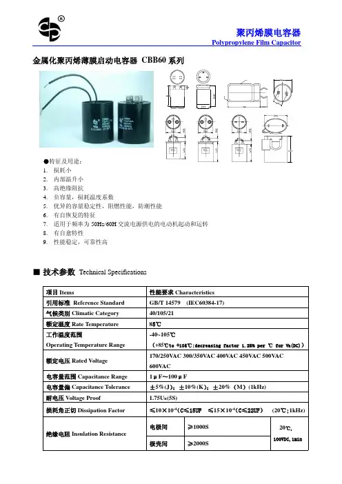
汇丰CBB60电容器规格书
- 格式:pdf
- 大小:952.18 KB
- 文档页数:4
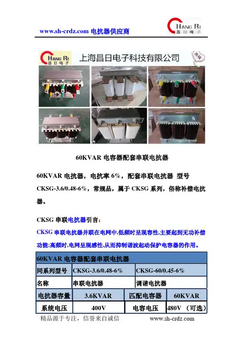
60KVAR电容器配套串联电抗器60KVAR电抗器,电抗率6%,配套串联电抗器型号CKSG-3.6/0.48-6%,常规品,属于CKSG系列,俗称补偿电抗器。
CKSG串联电抗器引言:CKSG串联电抗器并联在电网中,低频时呈现容性,主要起到无功补偿功能;高频时,电网呈现感性,从而抑制谐波起动保护电容器的作用。
60KVAR电容器配套串联电抗器同系列型号CKSG-3.6/0.48-6% CKSG-60/0.45-6%名称串联电抗器调谐电抗器电抗器容量 3.6KVAR 匹配电容器60KVAR系统电压400V 电容电压480V (可选)电压降16.63V 电流72A电感0.74MH 电抗率6%频率50HZ 品牌昌日冷却方式AN 防护等级Ip00串联电抗器适用于无功补偿系统中的电容器前端,抑制电网中的谐波,保护电容器的正常使用设计、制造、销售电抗器的企业,产品涵盖各种型号的进/出线电抗器、高/低压串/并联电抗器、滤波电抗器、平波电抗器、启动电抗器等;电压等级0.30KV,0.4KV,0.69KV ,10KV等,绝缘等级包括B级、F级、H级,可充分满足用户的不同需求。
300%订单式生产方式,满足客户实际需求。
产品系列有:JXL系列输入电抗器CXL系列输出电抗器CKSG系列串联电抗器CKSC系列高压串联电抗器一、60KVAR电容器配套串联电抗器作用接入串联电抗器,电容器电压升高系数- K=1 d 1如K= 6% 1.06 30.06 1≈-d =即运行电压升高6%,工作电流也随之大约6%。
运行经验认为,装有串联电抗器的电容器容量占2/3及以上时,则不会产生谐波谐振,能有效地吸收电网谐波,改善系统的电压波形,提高系的。
二, 60KVAR电容器配套串联电抗器型号说明三、60KVAR电容器配套串联电抗器性能参数1.可用于400V、660V系统。
2.电抗率的种类:1%、6%、12%3.额定绝缘水平3kV/min。
4.CKSG电抗器各部位的温升限值:铁芯不超过85K,电圈温升不超过95K。
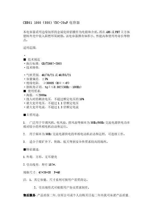
CBB611000(800)VDC-20uF电容器
本电容器采用边缘加厚的金属化锌铝膜作为电极和介质。
再在ABS或PBT立方体塑料外壳中装入阻燃环氧树脂。
该电容器拥有体积小,性能高和使用寿命长等特点。
适用范围:
·
■技术规范
·执行标准:GB/T3667-2005
·技术特性:
·气候类别:40/70/21或40/85/21
·容量偏差:±5%
·绝缘电阻:≥3000S(MΩ·µF)
·损耗角正切:tgδ≤0.002(50Hz~100Hz)
■使用要求:
·海拔:≤2000m
·投入时的剩余电压:不超过额定电压的10%
·最大允许电压:不超过1.1倍额定电压
·最大允许电流:不超过1.3倍额定电流
■主要用途:
1.广泛用于空调风机、电风扇、排风扇等频率为50Hz/60Hz交流电源供电功率相对较小的单相电机启动和运行。
2.用于频率为50Hz交流电源供电的单相电动机启动和运转,可连续工作。
3.适合于煤矿井下、铁路、航天等到安全性要求较高的场所。
■特征描述:
1.外观:方形、无耳塑壳
2.引出线有:焊片187#、
规格尺寸:47*26*38P=40
注:1、其它容量、尺寸系列可按用户需要商定。
2、引出端形式可根据用户协议要求制作。
售后服务:产品质保二年,任何公司或个人自购买日起二年内我司承诺产品质量.。
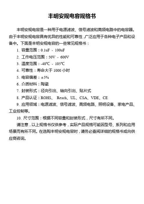
丰明安规电容规格书
丰明安规电容是一种用于电源滤波、信号滤波和高频电路中的电容器。
由于丰明安规电容具有优异的性能和可靠性,广泛应用于各种电子产品和设备中。
下面是丰明安规电容的一些常见规格书:
1. 容量范围:0.1uF - 100uF
2. 工作电压范围:50V - 600V
3. 温度范围:-40℃- 105℃
4. 可靠性:寿命大于1000小时
5. 电容偏差:±5%
6. 介质材料:陶瓷
7. 封装形式:径向引出、轴向引出、贴片式
8. 产品认证:ROHS、Reach、UL、CSA、VDE、CE
9. 应用领域:电源滤波、信号滤波、高频电路、照明设备、家电产品、工业控制等。
10. 尺寸范围:根据不同容量和封装形式,尺寸有所不同。
请注意,以上规格书仅供参考,实际产品规格可能因型号、系列和应用场景而有所不同。
在选购丰明安规电容时,请务必查阅详细的规格书或向供应商咨询。
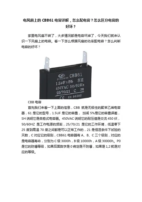
电风扇上的CBB61电容详解,怎么配电容?怎么区分电容的好坏?家里电风扇不转了,大多情况都是电容坏掉了,今天我们就来认识一下风扇上的电容。
看一下怎么根据风扇的功率配电容?怎么判断电容的好坏?CBB电容首先我们来看一下上面的信息,CBB就是无极性的聚苯乙烯电容器,61是它的型号,1.5UF是它的容量,加减5%是它的容量误差,SH说明它是自愈式电容器。
450VAC说明它的耐压值是交流450伏,50/60HZ是工作电源的频率,25/70/21是它的工作环境,低温零下25度到高温70度之间都是可以正常工作的,21是恒湿条件下试验的天数,C对应它的级别,CBB61电容器有A、B、C三个级别,对应的是电容器寿命,分别为C级3000h,B级10000h,A级30000h。
P0是它的防爆等级,如果后面数字是0肯定是不防爆,如果是1,2就是对应的等级。
CBB电容这个上面标注稍微有些不同,但是信息是类似的。
接电容电机一般是留有三根线,用万用表两两测一下电阻,电阻最大的两根线直接接电容。
接线图这个是接线图供大家参考,不同的电风扇接线稍有差异。
如果电扇不转确认是电容坏了,可以根据坏电容的型号再配一个,如果没有电容了,可以参考我给的数值。
40W左右的电风扇可以用1--1.5UF的电容,70W左右的电风扇可以用2UF的电容,180W左右的电风扇可以用3UF左右的电容。
如果电容容量太大会烧电机,电容太小启动不起来,只要不超过标配电容的20%都是可以的。
万用表电容档测电容测之前一定要先放电,这都是一些小容量的电容,可以两极快速的碰几下。
放电以后把万用表打到电容档,直接红黑表笔各接触一极就可以测出容量。
如果容量异常或者减小了很多就需要更换新的。
60mf电解电容内阻【最新版】目录1.电解电容的概述2.60mf 电解电容的特性3.60mf 电解电容内阻的影响因素4.如何测量 60mf 电解电容的内阻5.60mf 电解电容内阻的实际应用正文一、电解电容的概述电解电容,又称为电解电容器,是一种电子元件,其作用主要是储存电能,并在电路中滤波、耦合等。
它的主要构成部分是电极、电解质和外壳。
根据电极材料的不同,电解电容可分为铝电解电容、钽电解电容等。
根据容量的大小,电解电容可分为微型电解电容、大容量电解电容等。
在本文中,我们将重点讨论 60mf(即 60 微法拉)电解电容的内阻问题。
二、60mf 电解电容的特性60mf 电解电容具有以下特性:1.容量:60mf 电解电容的容量为 60 微法拉,属于中容量电解电容范畴。
2.电压:60mf 电解电容的额定电压一般为直流电压,如 35V、50V、100V 等,也有交流电压的电解电容,但较少见。
3.温度:60mf 电解电容的工作温度范围一般为 -40℃至 +85℃。
4.封装:60mf 电解电容有多种封装形式,如贴片式、插件式等,不同封装形式的电解电容适用于不同的电路设计和安装环境。
三、60mf 电解电容内阻的影响因素60mf 电解电容的内阻主要受以下因素影响:1.电极材料:电极材料的不同会导致电解电容的内阻差异,例如,铝电解电容的内阻通常比钽电解电容高。
2.电解质:电解质的性质和质量会影响电解电容的内阻,优质的电解质可以降低内阻。
3.封装形式:不同的封装形式对电解电容的内阻也有影响,如贴片式电解电容的内阻通常较低。
4.工作温度:电解电容的工作温度对其内阻有影响,温度过高或过低都可能导致内阻增大。
四、如何测量 60mf 电解电容的内阻测量 60mf 电解电容的内阻一般采用万用表或内阻测试仪进行。
以下是测量步骤:1.将 60mf 电解电容从电路中拆下,避免测量时影响其他元件。
2.使用万用表的电阻档,将红表笔接在电解电容的正极,黑表笔接在负极,此时万用表显示的电阻值即为电解电容的内阻。
60nf参数及代换【最新版】目录1.60nf 参数的基本概念2.60nf 参数的种类3.60nf 参数的代换原则4.60nf 参数的实际应用正文【60nf 参数的基本概念】60nf 参数,全称为 60 纳米薄膜电容器的参数,是一种用于描述薄膜电容器性能的重要指标。
在电子元器件领域,60nf 参数被广泛应用于衡量薄膜电容器的电容量、工作电压、温度特性等性能。
【60nf 参数的种类】60nf 参数主要包括以下几种:1.电容量:用来描述电容器存储电能的能力,单位为法拉(F)。
2.工作电压:指电容器在正常工作状态下所能承受的电压范围,单位为伏特(V)。
3.温度特性:描述电容器在不同温度下性能变化的特性,通常用温度系数表示,单位为 ppm/℃。
4.损耗因素:描述电容器在交流电路中能量损耗的指标,单位为%。
【60nf 参数的代换原则】在实际应用中,有时需要对 60nf 参数进行代换,以满足不同电路设计需求。
代换原则主要包括以下几点:1.电容量相近原则:代换时,应选择电容量相近的电容器,以保证电路性能不受影响。
2.工作电压匹配原则:代换电容器的工作电压应与原电容器相匹配,以确保电路的稳定性。
3.温度特性相似原则:代换电容器的温度特性应与原电容器相似,以保证电路在不同温度下的性能稳定。
4.损耗因素相近原则:代换电容器的损耗因素应与原电容器相近,以减小电路能量损耗。
【60nf 参数的实际应用】60nf 参数在实际应用中具有重要意义,广泛应用于以下领域:1.电源滤波:通过选用合适的 60nf 参数电容器,可以有效滤除电源中的高频噪声,保证电路的稳定性。
2.信号耦合:在信号耦合电路中,60nf 参数电容器可以实现信号的传输和隔离,提高电路的性能。
3.振荡电路:在振荡电路中,60nf 参数电容器可以影响振荡频率,从而调节电路的性能。
总之,60nf 参数作为描述薄膜电容器性能的重要指标,其代换原则和实际应用对于电路设计和优化具有重要意义。
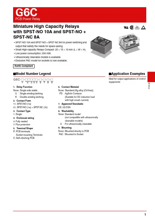
G 6CMiniature High Capacity Relays with SPST-NO 10A and SPST-NO + SPST-NC 8A•SPST-NO 10A and SPST-NO + SPST-NC 8A for power switching and output that satisfy the needs for space-saving.•Small High-capacity Relays Compact: 20 × 15 × 10 mm (L × W × H).•Low power consumption: 200 mW.•Ultrasonically cleanable models is available.•Exclusive P6C model for sockets is now available.■Model Number LegendRoHS CompliantG6C-@-@@@@@-@-@-@-@1234567891.Relay FunctionNone: Single-side stableU : Single-winding latching K : Double-winding latching 2.Contact Form 11: SPST -NO (1a)21: SPST -NO (1a) + SPST -NC (1b)3.Contact Type 1: Single4.Enclosure rating 4: Fully sealed 7: Flux protection5.Terminal Shape P: PCB terminalsSocket mounting T erminals C: Self-clinching PCB6.Contact MaterialNone: Standard (Ag-alloy (Cd free))FD : AgSnIn Contacts(Suitable for DC inductive load with high inrush current)7.Approved Standards US: UL/CSA8.WashabilityNone: Standard model(not compatible with ultrasonically cleanable models)U : For ultrasonically cleanable 9.MountingNone: Mounted directly to PCB P6C : Mounted to Socket■Application ExamplesIdeal for output applications of control equipmentsG6C PCB Power RelayG 6 C ■Ordering Information●Standard Models (UL, CSA certified)Relay Function Single-side stable Single-winding latching Double-winding latching Minimunpackingunit Enclosurerating Contact form TerminalsModelRated coilvoltageModelRated coilvoltageModelRated coilvoltageFluxprotectionSPST-NO (1a)Straight PCBG6C-1117P-US3 VDCG6CU-1117P-US3 VDCG6CK-1117P-US3 VDC100 pcs/tray5VDC5VDC5VDC6 VDC− 6 VDC12 VDC12 VDC12 VDC24 VDC24 VDC24 VDCG6C-1117P-FD-US5 VDCG6CU-1117P-FD-US5 VDCG6CK-1117P-FD-US−12 VDC12 VDC12 VDC24 VDC24 VDC−Self-clinchingPCBG6C-1117C-US3 VDC−−G6CK-1117C-US−5 VDC−−12 VDC−12 VDC24 VDC−24 VDCSPST-NO (1a) +SPST-NC (1b)Straight PCBG6C-2117P-US3 VDCG6CU-2117P-US3 VDCG6CK-2117P-US3 VDC5VDC5VDC5VDC6VDC6VDC6VDC12 VDC12 VDC12 VDC24 VDC24 VDC24 VDCG6C-2117P-FD-US5 VDCG6CU-2117P-FD-US5 VDCG6CK-2117P-FD-US5 VDC12 VDC12 VDC−24 VDC24 VDC24 VDCSelf-clinchingPCBG6C-2117C-US3 VDCG6CU-2117C-US−G6CK-2117C-US3 VDC5VDC5VDC5VDC6 VDC−−12 VDC12 VDC12 VDC24 VDC−24 VDCRelay Function Single-side stable Single-winding latching Double-winding latching Minimunpackingunit Enclosurerating Contact form TerminalsModelRated coilvoltageModelRated coilvoltageModelRated coilvoltageFullysealedSPST-NO (1a)Straight PCBG6C-1114P-US3 VDCG6CU-1114P-US3 VDCG6CK-1114P-US3 VDC100 pcs/tray5VDC5VDC5VDC6VDC6VDC6VDC12 VDC12 VDC12 VDC24 VDC24 VDC24 VDCG6C-1114P-FD-US5 VDCG6CU-1114P-FD-US5 VDCG6CK-1114P-FD-US5 VDC12 VDC12 VDC12 VDC24 VDC24 VDC24 VDCSelf-clinchingPCBG6C-1114C-US3 VDCG6CU-1114C-US−G6CK-1114C-US3 VDC5 VDC− 5 VDC12 VDC12 VDC12 VDC24 VDC−24 VDCSPST-NO (1a) +SPST-NC (1b)Straight PCBG6C-2114P-US3 VDCG6CU-2114P-US3 VDCG6CK-2114P-US3 VDC5VDC5VDC5VDC6VDC6VDC6VDC12 VDC12 VDC12 VDC24 VDC24 VDC24 VDCG6C-2114P-FD-US5 VDCG6CU-2114P-FD-US5 VDCG6CK-2114P-FD-US−12 VDC12 VDC−24 VDC24 VDC24 VDCSelf-clinchingPCBG6C-2114C-US3 VDCG6CU-2114C-US−G6CK-2114C-US−5VDC5VDC5VDC6 VDC− 6 VDC12 VDC−12 VDC24 VDC−24 VDCNote.When ordering, add the rated coil voltage to the model number.Example: G6C-1117P-US DC3However, the notation of the coil voltage on the product case as well as on the packing will be marked as @@ VDC.Rated coil voltageG6CPCB Power RelayG 6C●Ultrasonically Cleanable Models (UL, CSA certified)●Connecting Sockets (Sold Separately)Note e the G6C-@@@@P-US-P6C to mount to a P6C Socket.2.When using by combining sockets, the rated current will be 5A due to its rated switching current.Relay FunctionSingle-side stable Single-winding latching Double-winding latching Minimun packing unitEnclosure ratingContact formTerminalsModelRated coil voltage ModelRated coil voltageModelRated coil voltageFully sealedSPST -NO (1a)Straight PCBG6C-1114P-US-U3 VDC G6CU-1114P-US-U−G6CK-1114P-US-U−100 pcs/tray5 VDC5 VDC 5 VDC6 VDC −−12 VDC 12 VDC 12 VDC 24 VDC−24 VDC Self-clinchingPCB G6C-1114C-US-U12 VDC −−−−24 VDC −−SPST -NO (1a) + SPST -NC (1b)Straight PCBG6C-2114P-US-U5 VDC−−G6CK-2114P-US-U5 VDC12 VDC −12 VDC 24 VDC −−Self-clinchingPCBG6C-2114C-US-U 5 VDC −−−−12 VDC −−24 VDC−−Applicable relays ModelMinimun packing unitG6C-2114P-US-P6C G6C-2117P-US-P6C G6C-1114P-US-P6C G6C-1117P-US-P6C G6CU-2114P-US-P6C G6CU-2117P-US-P6C G6CU-1114P-US-P6C G6CU-1117P-US-P6C P6C-06P20 pcs/tubeG6CK-2114P-US-P6C G6CK-2117P-US-P6C G6CK-1114P-US-P6C G6CK-1117P-US-P6C P6C-08P Removal Tool P6B-Y11Hold-down ClipsP6B-C2Note.When ordering, add the rated coil voltage to the model number.Example: G6C-1114P-US-U DC3However, the notation of the coil voltage on the product case as well as on the packing will be marked as @@ VDC.Rated coil voltageG6C PCB Power RelayG 6 C ■RatingsCoil: 1-Pole, Single-side Stable Type (Including models for ultrasonically cleanable)Coil: Single-winding Latching Type (Including models for ultrasonically cleanable)Coil: Double-winding Latching Type (Including models for ultrasonically cleanable)Note 1.The rated current and coil resistance are measured at a coil temperature of 23°C with a tolerance of ±10%.2.The operating characteristics are measured at a coil temperature of 23°C.3.The “Max. voltage” is the maximum voltage that can be applied to the relay coil.ContactNote.The values shown in parentheses () are for -FD models only.ItemRatedcurrent(mA)Coilresistance(Ω)Must operatevoltage(V)Must releasevoltage(V)Max.voltage(V)Powerconsumption(mW)Rated voltage% of rated voltage3 VDC674570% max.10% min.160%(at 23°C)Approx. 2005 VDC401256 VDC33.318012 VDC16.772024 VDC8.32,880ItemRatedcurrent(mA)Coilresistance(Ω)Must setvoltage(V)Must resetvoltage(V)Max.voltage(V)Power consumptionRated voltageSet coil(mW)Reset coil(mW)% of rated voltage3 VDC674570% max.70% max.160%(at 23°C)2002005 VDC401256 VDC33.318012 VDC16.772024 VDC8.32,880Item Rated current (mA)Coil resistance (Ω)Must setvoltage(V)Must resetvoltage(V)Max.voltage(V)Power consumption Rated voltageSet coil Reset coil Set coil Reset coilSet coil(mW)Reset coil(mW)% of rated voltage3 VDC93.593.532.132.170% max.70% max.130%(at 23°C)2802805 VDC56.056.089.389.36 VDC46.746.712912912 VDC23.323.351451424 VDC11.711.72,0562,056Contact FormRated loadItemSPST-NO (1a)SPST-NO (1a) + SPST-NC (1b)Resistive loadInductive load(cosφ = 0.4; L/R = 7 ms)Resistive loadInductive load(cosφ = 0.4; L/R = 7 ms)10 A (8 A) at 250 VAC10 A (10 A) at 30 VDC5 A (5 A) at 250 VAC5 A (5 A) at 30 VDC8 A (8 A) at 250 VAC8 A (8 A) at 30 VDC3.5 A (3.5 A) at 250 VAC3.5 A (3.5 A) at 30 VDC Contact type SingleContact material Ag-Alloy (Cd free)Rated carry current10 A (10 A)8 A (8 A)Max. switching voltage380 VAC, 125 VDCMax. switching current10 A (10 A)8 A (8 A)G6CPCB Power RelayG 6C■Characteristics (Including models for ultrasonically cleanable)■Engineering DataItem Classification Single-side StableSingle-winding Latching Double-winding LatchingContact resistance *130 m Ω max.Note.The given values are initial values.*1.Measurement conditions: 5 VDC, 1 A, voltagedrop method.*2.Testing conditions: measured with a 500 VDCmegohmmeter (at 250 VDC between set/reset coil).*3.This value was measured at a switchingfrequency of 120 operations/min.Operate (set) time 10 ms max.Release (reset) time 10 ms max.Min. set pulse width −20 ms (at 23°C)Min. reset pulse width−20 ms (at 23°C)Insulationresistance *2Between coil and contacts1,000 M Ω min.Between contacts of the same polarity 1,000 M Ω min.Between contacts ofdifferent polarity1,000 M Ω min. (SPST-NO, SPST-NC)Between set and reset coils−−1,000 M Ω min.Dielectricstrength Between coil and contacts2,000 VAC 50/60Hz for 1min Between contacts of the same polarity 1,000 VAC 50/60Hz for 1minBetween contacts ofdifferent polarity2,000 VAC 50/60Hz for 1min (SPST -NO, SPST -NC)Between set and reset coils−−250 VAC 50/60Hz for1minVibrationresistance Destruction 10 to 55 to 10 Hz, 0.75 mm single amplitude (1.5 mm double amplitude)Malfunction10 to 55 to 10 Hz, 0.75 mm single amplitude (1.5 mm double amplitude)Shockresistance Destruction 1,000 m/s 2Malfunction100 m/s 2DurabilityMechanical50,000,000 operations min. (at 18,000 operations/hr)Electrical100,000 operation min. (at 1,800 operations/hr under rated load)Failure rate (P level) (reference value) *310 mA at 5 VDCAmbient operating temperature -25°C to 70°C (with no icing or condensation)Ambient operating humidity 5% to 85%WeightApprox. 5.6 g●Maximum Switching Capacity G6C-1114@-US G6C-1117@-USG6C-1114@-FD-US G6C-1117@-FD-USG6C-2114@-US G6C-2117@-USG6C-2114@-FD-US G6C-2117@-FD-USS w i t c h i n g c u r r e n t (A )Switching voltage (V)S w i t c h i n g c u r r e n t (A )Switching voltage (V)S w i t c h i n g c u r r e n t (A )Switching voltage (V)S w i t c h i n g c u r r e n t (A )Switching voltage (V)G6C PCB Power RelayG 6 C ●DurabilityG6C-1114@-US, G6C-2114@-USG6C-1117@-US, G6C-2117@-USG6C-1114@-FD-US, G6C-2114@-FD-USG6C-1117@-FD-US, G6C-2117@-FD-US●Ambient Temperature vs.Maximum Coil Voltage●Ambient Temperature vs MustOperate and Must Release voltagesNote.The maximum coil voltage refers to themaximum value in a varying range ofoperating power voltage, not a continuousvoltage.●Shock Malfunction●Magnetic Interference (between Relays)Sample: G6C-2114P-US DC24VNumber of Relays: 6 pcsTest conditions: Shock is applied in ±X, ±Y, and ±Zdirections three times each with without energizing theRelays to check the number of malfunctions.Requirement: 100 m/s2Durability(×14operations)S w itching c u rrent (A)Durability(x14operations)S w itching c u rrent (A)Maximumcoilvoltage(%)Ambient temperature (°C)200180160140130120100806010 202330 40 50 60 70 80 90MustOperateandMustReleasevoltages(%)Ambient temperature (°C)ZShock directionYEnergized De-energizedChangerateonthebasisofratedvalue(OV)(%)l2=5.08a l2=7.62a l2=10.16aG6CPCB Power RelayG 6C■Dimensions* A v erage v al u e* A v erage v al u e2-pole2-pole1-pole1-poleDimensions in pointed b rackets < > are for the Relay mo u nted to Socket (-P6C).Flux Protection Model (Straight PCB)G6C-@117P (-FD) -USPCB Mounting Holes (Bottom View)Tolerance: ±0.1Terminal Arrangement/Internal Connections (Bottom View)Check carefully the coilpolarity of the Relay.Flux Protection Model (Self-clinching PCB) G6C-@117C-US* A v erage v al u e2-pole1-pole 1-poleDimensions in pointed b rackets < > are for the Relay mo u nted to Socket (-P6C).Fully Sealed Model (Straight PCB)G6C-@114P (-FD) -USPCB Mounting Holes(Bottom View)Tolerance: ±0.1Terminal Arrangement/Internal Connections (Bottom View)Fully Sealed ModelG6C PCB Power RelayG 6 C* A v erage v al u e2-pole2-pole1-pole1-pole* A v erage v al u e(2.4)(2.4)Dimensions in pointed b rackets < >are for the Relay mo u nted to Socket (-P6C).Flux ProtectiveSingle-winding Latching Model(Straight PCB)G6CU-@117P (-FD) -USPCB Mounting Holes(Bottom View)Tolerance: ±0.1Terminal Arrangement/Internal Connections(Bottom View)Note:Check carefully the coilpolarity of the Relay.S: Set coilR: Reset coilFlux ProtectiveSingle-winding Latching Model(Self-clinching PCB)G6CU-@117C-US2-pole2-pole1-pole1-pole* A v erage v al u eDimensions in pointed b rackets < > arefor the Relay mo u nted to Socket (-P6C).Fully Sealed ModelSingle Latching Models(Straight PCB)G6CU-@114P (-FD) -USPCB Mounting Holes(Bottom View)Tolerance: ±0.1Terminal Arrangement/Internal Connections(Bottom View)Note:Check carefully the coilpolarity of the Relay.S: Set coilR: Reset coilFully Sealed ModelSingle Latching Models(Self-clinching PCB)G6CU-@114C-USG6CPCB Power RelayG 6C2-pole2-pole1-pole1-pole* A v erage v al u e* A v erage v al u e0.65<0.7>Dimensions in pointed b rackets < > are for the Relay mo u nted to Socket (-P6C).Flux ProtectiveDouble-winding Latching Model (Straight PCB)G6CK-@117P (-FD) -USPCB Mounting Holes (Bottom View)Tolerance: ±0.1Terminal Arrangement/Internal Connections (Bottom View)Check carefully the coilpolarity of the Relay.S: Set coil R: Reset coilFlux ProtectiveDouble-winding Latching Model (Self-clinching PCB) G6CK-@117C-US(2.4)* A v erage v al u e* A v erage v al u e2-pole2-pole1-pole1-pole0.65<0.7>Dimensions in pointed b rackets < > are for the Relay mo u nted to Socket (-P6C).(2.4)Fully SealedDouble-winding Latching Model (Straight PCB)G6CK-@114P (-FD) -USPCB Mounting Holes (Bottom View)Tolerance: ±0.1Terminal Arrangement/Internal Connections (Bottom View)Check carefully the coilpolarity of the Relay.S: Set coil R: Reset coilFully SealedDouble-winding Latching Model (Self-clinching PCB)G6CK-@114C-USG6C PCB Power RelayG 6 C ■Connecting Sockets DimensionsSocket for single-winding latching/single-side a table ModelsP6C-06PSocket for double-winding latching ModelsP6C-08PPCB Mounting Holes(BOTTOM VIEW)T olerance: ±0.1 mm11G6CPCB Power RelayG 6C■Approved Standards●The rated values approved by each of the safety standards may be different from the performance characteristics individually defined in this catalog.UL Recognized (File No. E41643) CSA Certified(File No. LR31928)EN/IEC, VDE Certified(Certificate No. 40014439)EN/IEC, TÜV Certified(Registration No. R50158249)ModelNumber of polesCoil ratingsContact ratingsNumber of test operationsG6C ()13 to 24 VDC10 A, 250 VAC (General use) 80°C 10 A, 30 VDC (Resistive) 80°C1/6 HP 125 VAC, 1/4 HP , 125 VAC 80°C 1/3 HP 250 VAC, 1/4 HP , 250 VAC 80°C600 W, 120 VAC, (Tungsten) 80°C (excluding -FD Models)6,000530 VA, 20 to 265 VAC Max 2A (Pilot Duty) 80°C 43.2 VA, 30 VDC (Pilot Duty) 80°C 6,00012 LRA, 2.2 FLA, 30 VDC 80°C30,0001,000 (-FD Models)28 A, 250 VAC (General use) 80°C 8 A, 30 VDC (Resistive) 80°C1/6 HP 125 VAC, 1/4 HP , 125 VAC 80°C 1/3 HP 250 VAC, 1/4 HP , 250 VAC 80°C600 W, 120 VAC, (Tungsten) 80°C (excluding -FD Models)6,000530 VA, 20 to 265 VAC Max 2A (Pilot Duty) 80°C 43.2 VA, 30 VDC (Pilot Duty) 80°C 6,00012 LRA, 2.2 FLA, 30 VDC 80°C30,0001,000 (-FD Models)ModelNumber of polesCoil ratings Contact ratingsApproved switchingoperationsG6C ()13, 5, 6, 12, 24 VDC10 A, 250 VAC (cos φ = 1) 40°C 5 A, 250 VAC (cos φ = 0.4) 40°C 20,0002•Single-stable:3, 5, 6, 12, 24 VDC7 A, 250 VAC (cos φ = 1) 40°C 3.5 A, 250 VAC (cos φ = 0.4) 40°CModelNumber of polesCoil ratingsContact ratingsApproved switchingoperationsG6C ()1•Single-stable:3, 5, 6, 12, 24 VDC •Latching:3, 5, 6, 12, 24 VDC10 A, 250 VAC (cos φ = 1) 40°C 5 A, 250 VAC (cos φ = 0.4) 40°C 10 A, 30 VDC (L/R = 0 ms) 40°C 20,00028 A, 250 VAC (cos φ = 1) 40°C 3.5 A, 250 VAC (cos φ = 0.4) 40°C 8 A, 30 VDC (L/R = 0 ms) 40°C■Removal ToolP6B-Y1■Hold-down ClipsP6B-C2G6C PCB Power RelayG 6 C ■Precautions●Please refer to “PCB Relays Common Precautions” for correct use.●Mounting•Do not reverse the polarity of the coil(+, −).•When mounting more than two relaysside by side, keep the gap betweenRelays as shown below to ensure agood heat dissipation. It may result inmalfunction if heat is not dissipatedsmoothly from the Relay.●Sockets•When mounting the Relay, make sureto insert the Relay terminalsperpendicularly and correctly into thesocket contact pin.•Hold-down clips (for mounting andremoval) are also available.•The P6C model has a flux-resistantconstruction. Do not wash it down withwater.•The max. carry current of sockets is 5A.•Not applicable to the self-clinching type.●Double-winding Latching Circuit•It is recommended to perform wiring ofNo.1 and No.2 of the negative (-)terminal as COM wiring, in order toimprove the operation stability forDouble-winding Latching.●Using SPDT contact of theSPST-NO+SPST-NC Relay•Do not construct a circuit so thatovercurrent and burning occur if theNO, NC and SPDT contacts are short-circuited with the SPST-NO+SPST-NCRelay. Arcing may generate short-circuiting between contacts if there isshort-circuiting because of conversionto the MBB contact caused byasynchronous operation of the NO andNC contacts, the interval between theNO and NC contacts is small, or alarge current is left open.●Other precautions•This Relay is a Power Relay which issuitable for power load switching. Donot use the G6C for signal purposessuch as micro load switching under10mA.Correct Usebetweenterminals(+Cat. No. K018-E1-110318(0207)(O) Please check each region's Terms & Conditions b y region w e b site.OMRON CorporationElectronic and Mechanical Components CompanyRe g ional ContactAmericas Europehttps:/// http://components.omron.e u/Asia-Pacific China https://ec .sg/ https://www.ec /Korea Japanhttps://www.omron-ec b.co.kr/ https://www.omron.co.jp/ec b/In the interest of prod u ct impro v ement, specifications are s ub ject to change w itho u t notice.© OMRO N Corporation 2007-2018 All Rights Reser v ed.12。
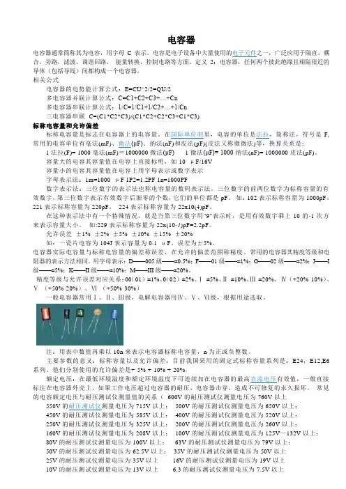
电容器电容器通常简称其为电容,用字母C表示。
电容是电子设备中大量使用的电子元件之一,广泛应用于隔直,耦合,旁路,滤波,调谐回路,能量转换,控制电路等方面。
定义2:电容器,任何两个彼此绝缘且相隔很近的导体(包括导线)间都构成一个电容器。
相关公式电容器的电势能计算公式:E=CU^2/2=QU/2多电容器并联计算公式:C=C1+C2+C3+…+Cn多电容器串联计算公式:1/C=1/C1+1/C2+…+1/Cn三电容器串联C=(C1*C2*C3)/(C1*C2+C2*C3+C1*C3)标称电容量和允许偏差标称电容量是标志在电容器上的电容量。
在国际单位制里,电容的单位是法拉,简称法,符号是F,常用的电容单位有毫法(mF)、微法(μF)、纳法(nF)和皮法(pF)(皮法又称微微法)等,换算关系是:1法拉(F)= 1000毫法(mF)=1000000微法(μF) 1微法(μF)= 1000纳法(nF)= 1000000皮法(pF)。
容量大的电容其容量值在电容上直接标明,如10 μF/16V容量小的电容其容量值在电容上用字母表示或数字表示字母表示法:1m=1000 μF 1P2=1.2PF 1n=1000PF数字表示法:三位数字的表示法也称电容量的数码表示法。
三位数字的前两位数字为标称容量的有效数宇,第三位数宇表示有效数字后面零的个数,它们的单位都是pF。
如:102表示标称容量为1000pF。
221表示标称容量为220pF。
224表示标称容量为22x10(4)pF。
在这种表示法中有一个特殊情况,就是当第三位数字用"9"表示时,是用有效数宇乘上10的-1次方来表示容量大小。
如:229表示标称容量为22x(10-1)pF=2.2pF。
允许误差±1% ±2% ±5% ±10% ±15% ±20%如:一瓷片电容为104J表示容量为0.1 μF、误差为±5%。
低压无功补偿装置 技术规范书技 术 规 范 书1. 总则1.1 本技术规范书适用于低压400V系统TSC无功功率动态补偿装置。
提出了并联电容器动态无功功率补偿装置的技术要求。
1.2 本技术规范提出的是最低限度的技术要求, 并未对一切技术细节作出规定,也未充分引述有关标准和规范的条文。
投标方应保证提供符合工业标准和本技术规范的优质产品。
1.3 本技术规范所使用的标准若与甲方所执行的标准不一致时,按较高标准执行。
1.4 本技术规范书未尽事宜,由双方协商解决。
2. 招标内容投标方提供满足本技术规范书要求的设备和各项服务,其中包括下列内容:➢提供高质量的、完整的、全新的设备和相关附件。
➢设备的现场指导安装、调试、现场验收等。
➢对买方技术人员的培训、保修期的维护等。
➢提供技术资料。
3. 资质要求➢要求供货厂家必须提供同类产品CCC认证资质证明;➢要求所提供产品必须获得国家权威部门即国家电控配电设备质量监督检验中心,出具的产品型式试验合格证书及报告;➢要求所提供产品必须具备质量管理体系认证证书(ISO9001);➢要求产品具有自主的专利证书;4. 供货范围动态补偿装置采用与低压柜并柜安装,投标方中标后需和前期中标的开关柜厂家密切配合以解决动态补偿成套装置和低压开关柜之间的并柜接口及采样方面的相关问题。
此次投标不包含补偿装置内的水平主母线(即柜顶主母线、零、地母线)、低压进线电流信号采集用电流互感器(甲方在低压进线柜中提供),此外为满足装置性能的所需的一次、二次元件包括柜体均由投标人成套提供,具体供货范围如下(参见图纸)。
表1 成套设备供货范围序号 型 号 单位 宽*深*高 mm1 JJH-0.4/405-6 台 1000*800*2200备注:低压400V系统,补偿装置安装容量405(kVar),电抗率6%备注:供货范围包含设备的设计、制造、水平母排至断路器的分支排、出厂检验、包装、运输、保险、调试以及技术培训等服务。
CONDUCTIVE POLYMER ALUMINUM SOLID ELECTROLYTIC CAPACITORSCAT.8500RRHS/RHA (φ8)
R1H2304J5369718M9C10N11112G13S14S
120Hz10 kHz100 kHz300 kHz1 kHz
0.100.501.001.000.45
管理记号3906.3
制品名表记3906.3尼吉康品号
FPCAP品号
RHARHSCONDUCTIVE POLYMER ALUMINUM SOLID ELECTROLYTIC CAPACITORS
CAT.8500R
RHS / RHA额定电压(V)(编码)浪涌电压(V)额定静电容量(µF)铝壳尺寸φD×L(mm)损失角正切值tanδ漏损电流(µA)(2分值/20℃)ESR(mΩ)(20℃/100kHz)额定纹波电流(mArms) (105℃/100kHz)品 号FPCAP品号
2.5(0E)2.86808×6.70.1270085000RHA0E681MCN1GSFP-2R5ME681M-HAR8208×11.70.1270095400RHS0E821MCN1GSFP-2R5ME821M-HSR8208×6.70.1270085000RHA0E821MCN1GSFP-2R5ME821M-HAR
10008×7.70.1275085000RHA0E102MCN1GSFP-2R5ME102M-HAR15008×11.70.12112595400RHS0E152MCN1GSFP-2R5ME152M-HSR
4.0(0G)4.65608×6.70.12700163200RHS0G561MCN1GSFP-4R0ME561M-HSR5608×6.70.1270085000RHA0G561MCN1GSFP-4R0ME561M-HAR6808×7.70.1281685000RHA0G681MCN1GSFP-4R0ME681M-HAR
电容的型号功能和应用的详细介绍1. [capacitanee ; electric capacity] 电容是表征电容器容纳电荷的本领的物理量,非导电体的下述性质:当非导电体的两个相对表面保持某一电位差时(如在电容器中),由于电荷移动的结果,能量便贮存在该非导电体之中定义: 电容是表征电容器容纳电荷的本领的物理量。
我们把电容器的两极板间的电势差增加1伏所需的电量,叫做电容器的电容。
电容的符号是Co在国际单位制里,电容的单位是法拉,简称法,符号是F,常用的电容单位有毫法(mF)、微法(卩F)、纳法(nF)和皮法(PF)(皮法又称微微法)等,换算关系是:1 法拉(F)= 1000 毫法(mF) = 1000000 微法(卩F) 1 微法(a F)= 1000 纳法(nF)= 1000000 皮法(pF)。
相关公式: 一个电容器,如果带1库的电量时两级间的电势差是1伏,这个电容器的电容就是1法,即:C二Q/U但电容的大小不是由Q或U决定的, 即:C=£ S/4 n kd。
其中,£是一个常数,S为电容极板的正对面积, d为电容极板的距离,k则是静电力常量。
常见的平行板电容器,电容为C=£ S/d.(£为极板间介质的介电常数,S为极板面积,d为极板间的距离。
)电容器的电势能计算公式:E二CU八2/2二QU/2 多电容器并联计算公式:C=C1+C2+C3++Cn 多电容器串联计算公式:1/C=1/C1+1/C2+…+1/C n电容器的型号命名方法第一部分I第二部分I第三部分I第四部分名称I材料I特征I序号C高频瓷T铁电T低频瓷W微调I玻璃J金属化J金属化M密圭寸L纸涤纶Y高压D铝电解C穿心式A钽电解S独石(渝r d电容器I符号I 意义I符号I意义I符号符号Y釉云母X 小型C Z纸介D电压用字母或数字电容功能分类介绍符号: 电容量:40p--4 a额定电压:63--630V 主要特点:小体积,大容量,耐热耐湿,稳定性差应用:对稳定性和损耗要求不高的低频电路名称:聚苯乙烯电容(CB 符号: 电容量:10 P--1 a额定电压:100V--30KV 主要特点:稳定,低损耗,体积较大应用:对稳定性和损耗要求较高的电路名称:聚丙烯电容(CBB 符号: 电容量:1000P--10 a额定电压:63--2000V 主要特点:性能与聚苯相似但体积小,稳定性略差应用:代替大部分聚苯或云母电容,用于要求较高的电路名称:云母电容(CY符号: 电容量:10p--0.1卩额定电压:100V--7kV 主要特点:高稳定性,高可靠性,温度系数小应用:高频振荡,脉冲等要求较高的电路名称:高频瓷介电容(CC 符号: 电容量:1--6800P 额定电压:63--500V 主要特点:高频损耗小,稳定性好应用:高频电路名称:低频瓷介电容(CT)符号: 电容量:10P--4.7卩额定电压:50V--100V 主要特点:体积小,价廉,损耗大,稳定性差应用:要求不高的低频电路名称:玻璃釉电容(CI)符号: 电容量:10p--0.1卩额定电压:63--400V 主要特点:稳定性较好,损耗小,耐高温(200度)应用:脉冲、耦合、旁路等电路名称:铝电解电容符号: 电容量:0.47--10000 a额定电压:63-450V 主要特点:体积小,容量大,损耗大,漏电大应用:电源滤波,低频耦合,去耦,旁路等名称:钽电解电容(CA铌电解电容(CN 符号: 电容量:0.1--1000 a额定电压:63-125V 主要特点:损耗、漏电小于铝电解电容应用:在要求高的电路中代替铝电解电容名称:空气介质可变电容器符号: 可变电容量:100--1500P 主要特点:损耗小,效率高;可根据要求制成直线式、直线波长式、直线频率式及对数式等应用:电子仪器,广播电视设备等名称:薄膜介质可变电容器符号: 可变电容量:15--550P 主要特点:体积小,重量轻;损耗比空气介质的大应用:通讯,广播接收机等名称:薄膜介质微调电容器符号: 可变电容量:1--29P 主要特点:损耗较大,体积小应用:收录机,电子仪器等电路作电路补偿名称:陶瓷介质微调电容器符号: 可变电容量:03-22P 主要特点:损耗较小,体积较小应用:精密调谐的高频振荡回路名称:独石电容容量范围:0.5 PF--1 M F耐压:二倍额定电压。