WM8805数据手册 中英文对照
- 格式:docx
- 大小:5.53 MB
- 文档页数:91

9.3功能说明9.3.1多路复用器9.3.2模拟输入9.3.3满量程(FSR)和LSB大小9.3.4参考电压9.3.5振荡器9.3.6数字比较器(仅ADS1114和ADS1115)9.3.7转换就绪引脚(仅适用于ADS1114和ADS1115)9.3.8 SMbus警报响应9.4设备功能模式9.4.1复位和上电9.4.2操作模式9.4.3低功耗的Duty Cycling9.5编程9.5.1 I2C接口9.5.2从模式操作9.5.3写入和读取寄存器9.5.4数据格式9.6Register Map9.6.1地址指针寄存器(地址= N / A)[reset = N / A]9.6.2转换寄存器(P [1:0] = 0h)[reset = 0000h]9.6.3配置寄存器(P [1:0] = 1h)[reset = 8583h]9.6.4 Lo_thresh(P [1:0] = 2h)[reset = 8000h]和Hi_thresh(P [1:0] = 3h)[reset = 7FFFh]10应用与实施10.1申请信息10.1.1基本连接10.1.2单端输入10.1.3输入保护10.1.4未使用的输入和输出10.1.5模拟输入滤波10.1.6连接多个设备10.1.7快速入门指南9.3功能说明9.3.1多路复用器ADS1115包含输入多路复用器(MUX),如图25所示。
可以测量四个单端或两路差分信号。
另外,AIN0和AIN1可以与AIN3差分测量。
多路复用器由Config寄存器中的MUX [2:0]位组成。
当测量单端信号时,ADC的负输入通过多路复用器内的开关内部连接到GND。
ADS1113和ADS1114没有输入多路复用器,可以测量一个差分信号或一个单端信号。
对于单端测量,将AIN1引脚连接到外部。
在本数据手册的后续章节中,AINP指的是AIN0,AINN是指ADS1113和ADS1114的AIN1。
CMS8M35xx 数据手册增强型1T 8051 电机微控制器 Rev. 1.07请注意以下有关CMS 知识产权政策*中微半导体(深圳)股份有限公司(以下简称本公司)已申请了专利,享有绝对的合法权益。
与本公司MCU或其他产品有关的专利权并未被同意授权使用,任何经由不当手段侵害本公司专利权的公司、组织或个人,本公司将采取一切可能的法律行动,遏止侵权者不当的侵权行为,并追讨本公司因侵权行为所受的损失、或侵权者所得的不法利益。
*中微半导体(深圳)股份有限公司的名称和标识都是本公司的注册商标。
*本公司保留对规格书中产品在可靠性、功能和设计方面的改进作进一步说明的权利。
然而本公司对于规格内容的使用不负责任。
文中提到的应用其目的仅仅是用来做说明,本公司不保证和不表示这些应用没有更深入的修改就能适用,也不推荐它的产品使用在会由于故障或其它原因可能会对人身造成危害的地方。
本公司的产品不授权适用于救生、维生器件或系统中作为关键器件。
本公司拥有不事先通知而修改产品的权利,对于最新的信息,请参考官方网站 。
1. 产品特性1.1 功能特性◆兼容MCS-51的1T指令系统- 系统时钟频率最高支持48MHz- 机器周期最快支持1T SYS @ F SYS≤24MHz- 机器周期最快支持2T SYS @ F SYS=48MHz ◆内存- 最大程序FLASH:16K×8Bit- 最大Data FLASH:1K×8Bit- 通用RAM:256×8Bit- 最大通用XRAM:1K×8Bit- 程序FLASH支持分区保护◆4种振荡方式- HSI-内部RC振荡:24MHz/48MHz- HSE-外部晶体振荡:8MHz/16MHz- LSE-外部晶体振荡:32.768KHz- LSI-内部低功耗振荡:125KHz◆低压复位功能(LVR)- 1.8V/2.0V/2.5V/3.5V◆低压检测功能(LVD)- 2.0V/2.2V/2.4V/2.7V/3.0V/3.7V/4.0V/4.3V ◆GPIO- 最多可达16个GPIO- 所有数字功能可分配到任意GPIO- 均支持上/下拉电阻功能- 均支持边沿(上升沿/下降沿/双沿)中断- 均支持唤醒功能◆中断源- 支持所有的外部端口中断- 最多达7个定时器中断- 其它外设中断◆定时器- WDT定时器(看门狗定时器)- 最多可达5个定时器:Timer0/1,Timer2,Timer3/4- LSE Timer(支持休眠唤醒功能)- WUT(唤醒定时器)- BRT(串口波特率时钟发生器)◆通信模块- 最多达1xSPI(通信速率最高可达6Mb/s)- 1xI2C(通信速率最高可达400Kb/s)- 最多达2xUART(波特率最高可达1Mb/s)◆低功耗模式- 空闲模式(IDLE)- 休眠模式(STOP)◆支持两线串行编程与调试◆工作电压范围- 2.1V~5.5V◆工作温度范围- -40℃~105℃◆蜂鸣器驱动- 50%占空比,频率可自由设置◆增强型PWM- 最多可达6通道增强型PWM- 最多可达6个相互独立周期计数器- 支持独立/互补/同步/成组模式- 支持边沿对齐/中心对齐方式- 支持互补模式死区延时功能- 支持掩码功能及刹车功能◆高精度12位ADC- 所有GPIO(16I/Os)均支持AD通道- 参考电压可选(1.2V/2.0V/2.4V/3.0V/VDD)- 可检测内部1.2V基准电压- 支持硬件触发启动转换功能- 支持一组结果数字比较功能◆两路模拟比较器(ACMP0/1)- 正端5种选择,负端可选内部1.2V/VDD分压- 比较器支持单边/双边迟滞- 迟滞电压可选10/20/60mV- 支持比较输出触发EPWM刹车- 负端内部1.2V/VDD分压可接内部ADC通道◆两路运算放大器(OP0/1)- 每个运放三端均和GPIO端口复用- 正端支持内部1.2V输入- 支持运放/比较器两种模式- 运放输出可接内部ADC通道- 运放输出可接内部模拟比较器输入- 支持失调电压软件修调◆可编程增益放大器(PGA)- 支持失调电压软件修调- 带采样保持电路(与ADC配合使用)- 多级增益可选(1/2/4/8/16/32/64/128倍)- 支持单端/伪差分输入- PGA输出可接内部ADC通道- PGA输出可接内部模拟比较器输入◆支持96位唯一ID号(UID)- 每颗芯片有独立的ID号1.2 产品对比2. 系统概述2.1 系统简介CMS8M35xx系列是8051内核、兼容MCS-51的1T指令系统、通用IO型的8位芯片,工作频率最高可达48MHz,该MCU具有如下特性:具有最大16KB 程序区、256B RAM空间、最大1KB XRAM、1KB 数据区。
AD9851中文数据手册By Hi_Cracker @whuCMOS180 MHzDDS / DAC合成器---------- AD9851FEATURES180 MHz的时钟速率可选6*参考时钟片上高性能10位DAC和高速滞回比较器无杂散动态范围(SFDR > 43分贝@70 MHzAout。
32bit 频率控制字便捷的编辑控制接口:并行或串行异步加载格式5位相位调制和偏置功能比较器抖动<80 ps的P-P在20兆赫2.7 V至5.25 V单电源供电低功耗:555毫瓦@180 MHz 掉电功能:4 mW@2.7 V 超小28引脚SSOP封装应用:频率/相位灵活可变的正弦波合成数字时钟恢复和锁定电路通信领域数控ADC编码发生器通信领域中灵活地本地振荡器正交振荡器CW,AM,FM,FSK MSK调制发射机GENERAL DESCRIPTIONAD9851是一个高度集成的器件,采用先进的DDS技术,结合内部高速,高性能D / A转换器,比较器,实现了一个数字可编程频率合成器和时钟发生器的功能。
引入一个精确的时钟源,AD9851可以产生一个稳定的,频率和相位可编程的正弦波。
此正弦波可以直接用作频率源或在内部转化为方波,然后作为灵活的时钟发生器使用。
AD9851的创新型高速DDS内核可以接受一个32位频率控制字,从而可以产生一个最大180 MHz的输出时钟,其分辨率约0.04Hz。
AD9851包含一个独特的6 * REFCLK乘法器电路,不再需要一个高速参考振荡器。
6 * REFCLK乘法器对SFDR和相位噪声的影响微乎其微。
AD9851提供分辨率为5位的相位调节,使其输出波形的相位的增量为11.25 °。
AD9851内部包含一个高速比较器,该比较器可以被配置为接受(外部)DAC的滤波输出,从而产生一个低抖动的输出脉冲。
频率的调谐,控制字以及相位调制字是通过并行或串行加载模式异步加载到AD9851中的。
8051内核-单片机This document contains information on a new product under development by Megawin. Megawin reserves the right to change ordiscontinue this product without notice.Megawin Technology Co., Ltd. 2005 All rights reserved.2014/02 version A1.0MA805-24/MA806-24说明书版本: A1.02MA805-24_MA806-24 说明书MEGAWIN功能●1-T 80C51 CPU●MA805-24_MA806-24 有24K字节闪存(Flash ROM)━ISP存储器空间1.5KB━IAP 大小为2.5KB (默认)。
AP代码没有用到的AP 闪存区可以设置作IAP用途。
━AP●片上256字节随机存取储存器和1024字节片上扩展存储器(XRAM)●双数据指针●为适应慢速SRAM或外围设备而可改变时长的MOVX指令●三个16位定时/计数器:定时器 0、定时器 1 及定时器 2━三个定时器输出口(T0CKO 对应 P34、T1CKO 对应 P35、T2CKO 对应P10)━T0/T1/T2时钟可以选择X12 模式●6个PCA (可编程计数器阵列)模块━捕获模式━16位软件定时器模式━高速输出模式━PWM (脉宽调节器) 模式●增强型UART (S0)━帧错误侦测━自动地址识别━速度改进机制(X2/X4模式)●副 UART (S1)━专用的波特率发生器━S1与S0复用波特率发生器●中断控制器━14 个中断源,4个优先级中断能力━4个外部中断输入 nINT0、 nINT1、 nINT2 及nINT3━nINT0/nINT1 触发类型:低电平或下降沿━nINT2/nINT3触发类型:低电平、下降沿、高电平或上升沿●8通道10位 ADC━可编程最高转换速率达 200 ksps━高达外部输入 (Single-ended)●主/从 SPI串行接口●端口2(P2)键盘中断●可编程看门狗定时器(WDT)━通过软件或上电一次性使能━MCU掉电模式下的WDT工作选项MEGAWIN MA805-24_MA806-24 说明书 3●LQFP48封装最大有45个普通I/O口(GPIO)━P0, P1, P2, P3, P4, P5 能被配置为准双向口、上拉输出、集电极开漏输出以及高阻输入━P6.0 和 P6.1 仅仅适合作准双向口模式及复用为 XTAL2和 XTAL1●两种省电模式:空闲模式(idle)和掉电模式(power-down)━空闲模式能被所有中断唤醒━掉电模式能被四个外部中断和键盘中断唤醒●掉电检测器(Brown-Out Detector):对于MA805系列是VDD低于4.2V ,对于MA806是VDD低于2.4V━掉电检测能选择复位或产生触发BOD中断●工作电压━MA805-24: 4.5V~5.5V.━MA806-24: 2.4V~3.6V. Flash相关操作不得低于 2.7V (ISP/IAP/ICP)●工作温度━工业级 (-40℃至 +85℃)*●工作频率:24MHz(最大,外部晶体)━外部晶体振荡器模式━内部有一个频漂为+/- 1%的高频率RC振荡器,内部振荡(出厂默认)频率为22.1184MHz**━内部高频率RC振荡输出脚为XTAL2/P6.0.━外部时钟输入脚为XTAL2/P6.0━内部低频率RC振荡器支持●封装类型━LQFP48: MA805-24AD,MA806-24AD━LQFP44: MA805-24AD44,MA806-24AD44━PDIP40: MA805-24AE,MA806-24AE (快速开发验证功能用,不推荐批量生产)*: 样品测试结果。
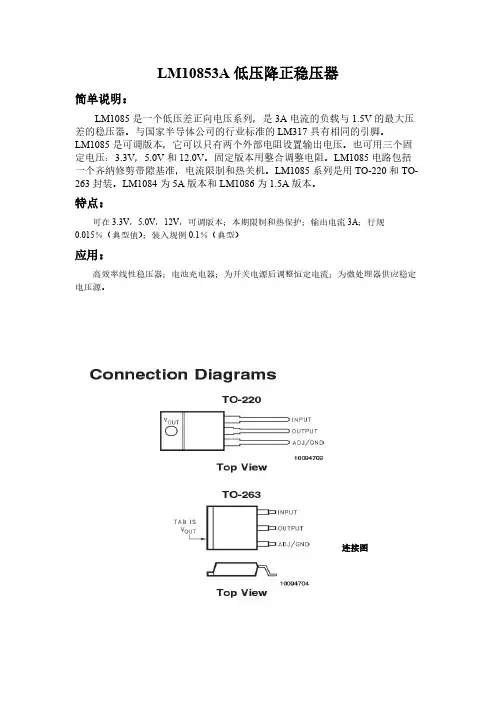
LM10853A低压降正稳压器简单说明:LM1085是一个低压差正向电压系列,是3A电流的负载与1.5V的最大压差的稳压器。
与国家半导体公司的行业标准的LM317具有相同的引脚。
LM1085是可调版本,它可以只有两个外部电阻设置输出电压。
也可用三个固定电压:3.3V,5.0V和12.0V。
固定版本用整合调整电阻。
LM1085电路包括一个齐纳修剪带隙基准,电流限制和热关机。
LM1085系列是用TO-220和TO-263封装。
LM1084为5A版本和LM1086为1.5A版本。
特点:可在3.3V,5.0V,12V,可调版本;本期限制和热保护;输出电流3A;行规0.015%(典型值);装入规例0.1%(典型)应用:高效率线性稳压器;电池充电器;为开关电源后调整恒定电流;为微处理器供应稳定电压源。
连接图实际应用图:基本功能框图:可调版本数据名称:PACKAGE(封装):TOP-220 TOP-263是封装尺寸Temperature Range(温度范围)Transport Media(传输介质)Tape and Reel(卷带式封装)Rails(导轨式封装)简化原理图:Absolute Maximum Ratings(最大额定值)(绝对最大额定值表明界限,可能会出现损坏设备。
经营评价显示设备的条件拟功能,但不能保证具体表现。
为保证规范和测试条件,见电气特性。
): Maximum Input to Output Voltage Differential(最大输入输出电压差)LM1085-ADJ 29VLM1085-12 18VLM1085-3.3 27VLM1085-5.0 25VPower Dissipation Internally Limited(功耗内部限制)(电流限制电路的功耗保持在安全范围内。
请参考应用笔记超载恢复。
) Junction Temperature (TJ)(结温)(最大功耗是TJ(MAX),θJA,和助教的功能。
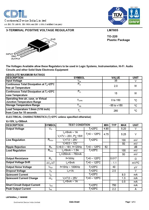
3-TERMINAL POSITIVE VOLTAGE REGULATOR LM7805 TO-220Plastic PackageThe Voltages Available allow these Regulators to be used in Logic Systems, Instrumentation, Hi-Fi Audio Circuits and other Solid State Electronic Equipment ABSOLUTE MAXIMUM RATINGS UNIT V W W ºC ºC ºCELECTRICAL CHARACTERISTICS (T j =25ºC unless specified otherwise)VI =10V, I O =500mA DESCRIPTION SYMBOLMINTYPMAXUNIT Output VoltageV OT j =25ºC4.805.20V I O =5mA ~ 1AV I =7V ~ 20V, P< 15W Line Regulation R EGV V I =7.0 ~ 25V T j =25ºC 100mV V I =8.0 ~ 12V50mV Ripple Rejection R R V I =8.0 ~ 18V, f=120HzT j =0 ~ 125ºC 62dB Load RegulationR EGL I O =5mA ~ 1.5A T j =25ºC100mV I O =250mA ~ 750mA50mV Output Resistance R O f=1KHz T j =0 ~ 125ºC 0.017ΩOutput Voltage Drift ∆V O /∆T I O =5mA T j =0 ~ 125ºC - 1.1mV/ºC Output Noise Voltage V NO f=10Hz ~ 100KHzT j =25ºC40µV Dropout Voltage V d I O =1AT j =25ºC 2.0V Quiescent CurrentI Q T j =25ºC8.0mA Quiescent Current Change ∆I Q V I =7.0 ~ 25V T j =0 ~ 125ºC 1.3mA I O =5mA ~ 1A0.5mA Short Circuit Output Current I SC T j =25ºC 750mA Peak Output CurrentI PKT j =25ºC2.2ATEST CONDITIONV T j =0 ~ 125ºC4.755.25Storage Temperature RangeT stg - 65 to +150Lead Temperature 1.6mm (1/16 inch) from Case for 10 seconds T L260Continuous Total Dissipation at T c =25ºC case TemperatureP D 15Operating free-air, case, or Virtual Junction Temperature Range T OPR 0 to 150DESCRIPTION SYMBOL VALUE Input VoltageV IN 35Continuous Total Dissipation at T a =25ºC free air TemperatureP D2.0Continental Device India LimitedAn ISO/TS 16949, ISO 9001 and ISO 14001 Certified CompanyTO-220Leaded PlasticPackageMRegulatorsPin 1: In Pin 2: Ground Pin 3: OutPackaging dimensions, tube dimensions and quantity/tube are approximate and subject to change.TO-220 Series Packaging TubeLM7805 TO-220Plastic PackageCustomer Notes LM7805TO-220Plastic PackageDisclaimerThe product information and the selection guides facilitate selection of the CDIL's Semiconductor Device(s)best suited for application in your product(s)as per your requirement.It is recommended that you completely review our Data Sheet(s)so as to confirm that the Device(s)meet functionality parameters for your application.The information furnished in the Data Sheet and on the CDIL Web Site/CD are believed to be accurate and reliable.CDIL however,does not assume responsibility for inaccuracies or incomplete information.Furthermore,CDIL does not assume liability whatsoever,arising out of the application or use of any CDIL product;neither does it convey any license under its patent rights nor rights of others.These products are not designed for use in life saving/support appliances or systems.CDIL customers selling these products(either as individual Semiconductor Devices or incorporated in their end products),in any life saving/support appliances or systems or applications do so at their own risk and CDIL will not be responsible for any damages resulting from such sale(s).CDIL strives for continuous improvement and reserves the right to change the specifications of its products without prior notice.CDIL is a registered Trademark ofContinental Device India LimitedC-120 Naraina Industrial Area, New Delhi 110 028, India.Telephone + 91-11-2579 6150, 4141 1112 Fax + 91-11-2579 5290, 4141 1119*****************。

AD9880中文数据手册全文翻译自:ADI公司AD9880B 数据手册英文AD9880数据手册版本号: Rev. 0简单描述AD9880是一个集模拟接口和HDMI接口于一体单个芯片,并且还支持HDCP。
1.1模拟接口AD9880是一个真正8位的150MSPS的单片模拟接口,用于对复合视频(YPbPr)和RGB图像信号的采集。
有150MSPS的编码速率和330MHz的带宽,所以支持全部HDTV 格式(最高1080p)和最高SXGA(1280*1024@75Hz)的FED。
Ad9880模拟接口内部包含有一个带1.25V基准的3态ADC,一个锁相环(PLL),增益、偏置、箝位控制均可编程。
用户只需提供1.8V和3.3V电压、模拟输入和Hsync信号。
三态CMOS输出的供电范围1.8V到3.3V。
片内锁相环从Hsync信号可以产生像素时钟信号,输出频率从12MHz到150MHz。
时钟抖动(clock jitter)在150MHz情况下,小于700ps p-p。
AD9880还能为复合同步以及sync-on-green(SOG)提供全同步处理。
1.2数字接口AD9880接收器符合HDMI 1.1规范,支持所有HDTV格式和显示公式。
The receiver features an intrapair skew tolerance of up to one full clock cycle。
在HDCP方案下,显示器可以接收加密的视频信号。
AD9880可以应用于视频接收的认证,在接收端对编码后的视频信号进行解密。
借助于先进的CMOS工艺,AD9880提供100管脚的LQFP表贴无铅封装。
温度范围0-70摄氏度。
2.管脚功能描述Table 5. pin function descriptions管脚号说明输入管脚R AIN0红色模拟输入通道0G AIN0绿色模拟输入通道0B AIN0蓝色模拟输入通道0R AIN0红色模拟输入通道1G AIN0绿色模拟输入通道1B AIN0蓝色模拟输入通道1红、绿、蓝三个模拟色彩信号输入通道都是高阻抗输入。
找电子元器件网上商城就上万联芯城,万联芯城销售IC 电子元器件,芯片,电阻,电容,二极管,三极管等多种类别,现货型号能够满足各种物料需求,如需要BOM物料清单配套,只需提交BOM表,商城会在短时间内反馈整单报价,为客户节省采购成本,满足客户物料需求,点击进入万联芯城。
(LM7805) (参考测试电路 QC T J 125QC,I 0 = 1A,V I = 16V,C I = 0.33PF,C 0 = 0.1PF,除非另有说明) 注28:LM7805恒定结温下指定负载和线路调节. 必须分别考虑因加热效应而导致的 V O 变化 . 脉冲测试低使用率.注29:这些参数虽然有保证,但在生产中未经100%测试.参数符号条件敏典型马克斯单位输出电压 V O T J = 25QC 9.8 10.0 10.2 V I O = 5MA至1A,P O D 15W,V I = 12.8V至25V 9.6 10.0 10.4线路调整 REGLINE V I = 12.8V至26V,I O = 500MA - 8 100毫伏 (注28) V I = 13V至20V - 4 50.0 T J = 25QCV I = 12.5V 至25V - 8 100 V I = 13V至20V - 3.0 50.0负载调节 REGLOAD T J = 25QC,I O = 5MA至1.5MA - 12.0 100毫伏 (注28) I O = 5MA至1MA - 12.0 100 I O = 250MA至750MA - 5 50.0静态电流 我 问 T J = 25QC- 5 6嘛静态电流变化 I O = 5MA至1A - - 0.5嘛 V I = 12.8V至25V,I O = 500MA - - 0.8 V I = 13V至26V,T J = 25QC- - 0.5输出电压漂移(注29) - 1.0 - 毫伏/ QC输出噪声电压 V N F = 10HZ至100KHZ,T A = 25QC - 10.0 - PV / V O纹波抑制(注29) RR F = 120HZ,I O = 500MA,V I = 14V至24V - 62.0 - D B压差电压 V DROP I O = 1A,T J = 25QC- 2.0 - V输出电阻(注29) RO F = 1KHZ - 17.0 - 米 :短路电流 我 SC V I = 35V,T A = 25QC- 250 - 嘛峰值电流(注29) 我 PK T J = 25QC- 2.2 - 一个恒定结温下指定负载和线路调整. V O 因热效应而 LM7805变化应分开考虑.使用低功率脉冲测试. 15.这些参数虽然有保证,但在生产中未经100%测试.符号参数条件闵.典型.大.单元 V O输出电压 T J = + 25℃ 14.40 15.00 15.60 V I O = 5MA至1A,P O≤15W, V I = 17.5V 至30V 14.25 15.00 15.75 REGLINE 线路调整 (14) T J = + 25℃ V I = 17.5V至30V 11 300毫伏 V I = 20 V至26 V 3 150 REGLOAD 负载调整 (LM7805) (参考测试电路. 40QC T J 125QC,I 0 = 500MA,V I = 19V,C I = 0.33PF,C 0 = 0.1PF,除非另有说明) LM7805注12:负载和线路调节在恒定结温下指定. 必须分别考虑因加热效应而导致的 V O 变化 . 脉冲测试低使用率.注13:这些参数虽然有保证,但在生产中未经100%测试.电气特性(LM7815) (参考测试电路. 40QC T J 125QC,I 0 = 500MA,V I = 23V,C I = 0.33PF,C 0 = 0.1PF,除非另有说明) 注14:负载和线路调节在恒定结温下指定. 必须分别考虑因加热效应而导致的 V O 变化 . LM7805脉冲测试低使用率.注15:这些参数虽然有保证,LM7805但在生产中未经100%测试.参数符号条件敏典型马克斯单元输出电压 V O T J = 25QC 11.5 12.0 12.5 V 5毫安 D I O D 1A,P O D 15W,V I = 14.5V至27V 11.4 12.0 12.6线路调整 REGLINE T J = 25QCV I = 14.5V至30V - 10.0 240毫伏 (注12) V I = 16V至22V - 3.0 120负载调节 REGLOAD T J = 25QCI O = 5MA至1.5MA - 11.0 240毫伏 (注12) I O = 250MA至750MA - 5 120静态电流 我 问 T J = 25QC- 5.1 8嘛静态电流变化 I O = 5MA至1A - 0.1 0.5嘛 V I = 14.5V至30V - 0.5 1.0输出电压漂移(注13) - 1.0 - 毫伏/ QC输出噪声电压 V N F = 10HZ至100KHZ,T A = 25QC - 76.0 - PV / V O纹波抑制(注13) RR F = 120HZ,V I = 15V 至25V 55.0 71.0 - D B压差电压 V DROP I O = 1A,T J = 25QC- 2.0 - V输出电阻(注13) RO F = 1KHZ - 18.0 - 米 :短路电流 我 SC V I = 35V,T A = 25QC- 230 - 嘛峰值电流。
广州大彩光电科技有限公司版权所有版本记录版本日期修改原因页面撰写人审核人V1.02023/02/06创建文档all林青田林绍佳销售与服务广州大彩光电科技有限公司电话:************-601传真:************Email:*************(咨询和支持服务)网站:地址:广州黄埔区(科学城)玉树华新园C栋3楼网络零售官方旗舰店:https://成都分公司电话:************地址:成都市高新区天府大道中段500号东方希望天祥广场C座39楼3910号目录1.硬件介绍 (1)1.1产品外观 (1)1.2硬件配置 (1)1.3调试工具 (2)2.产品规格 (3)3.产品尺寸 (6)4.引脚定义 (7)4.1HY2.0-8P(主推) (7)4.2FPC1.0-10P(选配) (7)5.可靠性测试 (8)5.1ESD测试 (8)5.1.1执行标准 (8)5.1.2测试环境 (8)5.1.3测试数据 (8)5.2高低温老化测试 (9)5.2.1测试环境 (9)5.2.2测试数据 (9)5.3群脉冲测试 (10)5.3.1执行标准 (10)5.3.2测试环境 (10)5.3.3测试数据 (10)5.4辐射测试 (11)5.4.1执行标准 (11)5.4.2测试环境 (11)5.4.3测试数据 (11)6.型号定义 (13)7.RS232与TTL电平转换 (14)8.协议配置 (15)9.LUA脚本配置 (16)10.包装与物理尺寸 (17)11.产品架构 (18)12.开发软件 (19)12.1什么是虚拟串口屏 (19)12.2Keil与虚拟串口屏绑定调试 (20)13.开发文档 (21)14.免责声明 (22)销售咨询:************-601Email:*************1.硬件介绍本章节主要介绍产品的一些外观参考图、硬件配置图和调试所需工具。
1.1产品外观以下为该尺寸不同型号的外观参考图,如图1-1、图1-2、图1-3所示。
AD9851中文数据手册By Hi_Cracker @whuCMOS180 MHzDDS / DA (合 成器AD9851FEATURES32bit 频 率便捷的编辑控制接口:并行或串行 异步加载格式5位相位调制和偏置功能比较器抖动<80 ps 的P-P 在20兆赫2.7 V 至5.25 V 单电源供电 低功耗:555毫瓦@180 MHz 掉电功能:4 mW@2.7 V超小28引脚SSOP 封装 应用:频率/相位灵活可变的正弦波合成数字时钟恢复和锁定电路通信领域数控ADC 编码发生器通信领域中灵活地本地振荡器正交振荡器CW ,AM ,FM ,FSK MSK 调制发射机GENERAL DESCR IP TIONAD9851是一个高度集成的器件,采用先进的性能D / A 转换器,比较器,实现了一个数字可编程频率合成器和时钟发生器 的功能。
引入一个精确的时钟源, AD9851可以产生一个稳定的, 频率和相位 可编程的正弦波。
此正弦波可以直接用作频率源或在内部转化为方波,然后 作为灵活的时钟发生器使用。
AD9851的创新型高速 DDS 内核可以接受一个 32位频率控制字,从而可以产生一个最大 180 MHz 的输出时钟,其分辨率约0.04Hz 。
AD9851包含一个独特的6 * REFCLK 乘法器电路,不再需要一个高速 参考振荡器。
6 * REFCLK 乘法器对SFDR 和相位噪声的影响微乎其微。
AD9851180 MHz 的时钟速率可选 6*参考时钟片上高性能10位DAC 和高速滞回比较器无杂散动态范围(SFDR > 43分贝@70 MHzAout 。
控DDS 技术,结合内部高速,高提供分辨率为5位的相位调节,使其输出波形的相位的增量为11.25 °。
AD9851内部包含一个高速比较器,该比较器可以被配置为接受(外部) DAC的滤波输出,从而产生一个低抖动的输出脉冲。
频率的调谐,控制字以及相位调制字是通过并行或串行加载模式异步加载到AD9851中的。
BMP085数字气压传感器中文手册关键特性压力范围:300···1100hpa(+9000m···-500m海拔高度)电压范围:1.8···3.6V(V DDA)1.62···3.6V(V DDD)封装大小:长宽5*5mm高1.2mmLow power····Low noise····--内含温度测量--I2C接口--全标准(内含标准数据校准)--不含铅,卤族元素,符合限制在电子电气产品中使用有害物质的指令--MSL1BMP085与SMD500新特性比较典型应用。
加强gps导航能力(航位推测法,斜坡探测等)。
航海。
休闲和运动。
天气预报。
垂直速度指示(上升下降速度)BMP085一般说明(总则):BMP085作为新一代高精度气压传感器与SMD500的功能和引脚是完全兼容的。
通用的SMD500/BMP085C代码(BMP085-SMD500-API)与SMD500也是兼容的,但是要注意器件ID。
正在使用SMD500气压传感器的用户如果打算使用BMP085气压传感器并得到第一手资料,请尽快联系BOSCH公司。
BMP085的低功耗、低电压的电学特性使它可以很好的适用于手机、PDA、GPS导航器件以及户外装备上。
BMP085在低的高度噪声(merely0.25)快速转换的情况下,表现很好。
BMP085是基于压阻效应技术的,具有稳定的电磁兼容性、高精度、线性性以及稳定性。
Bosch公司的气压传感器(在自动控制应用领域)是世界市场上的领军,基于200百万气压传感器这制造经验,BMP085继续了新一代的微型气压传感器。
目录1.电学特性2.绝对最大额定参数3.操作手册3.1总述3.2功能和应用3.3温度和压强的测量3.4校准系数3.5温度压强的计算3.6绝对高度的计算3.7海平面压强的计算4.I2C接口4.1I2C规格4.2器件和寄存器地址4.3I2C协议4.4开始温度和压强测量4.5读AD转换结果或者E2PROM数据5.封装5.1引脚配置5.2轮廓规模5.3器件标志5.4tape on reel5.5印刷电路板设计5.6湿度敏感水平和焊接5.7符合限制在电子电气产品中使用有害物质的指令5.8装配推荐6.免责声明6.1工程例子6.2产品应用6.3应用例子和提示7.document history and modifications1.电学特性如果没有另作规定,以下所给的值是在电压温度范围内的最大值。
1Features•Compatible with:•Bellcore GR-30-CORE, SR-TSV-002476, ANSI/TIA/EIA-716, TIA/EIA-777;•ETSI ETS 300 778-1 (FSK only variant) & -2;•BT (British Telecom) SIN227 & SIN242•Bellcore ‘CPE Alerting Signal’ (CAS), ETSI ‘Dual Tone Alerting Signal’ (DT-AS), BT Idle State and Loop State ‘Tone Alert Signal’ detection •1200 baud Bell 202 and CCITT V.23 FSK demodulation•Separate differential input amplifiers withadjustable gain for Tip/Ring and telephone hybrid or speech IC connections•Selectable 3-wire FSK data interface (bit stream or 1 byte buffer)•Facility to monitor the stop bit for framing error check•FSK Carrier detect status output • 3 to 5V +/- 10% supply voltage•Uses 3.579545MHz crystal or ceramic resonator •Low power CMOS with power downApplications•Bellcore CID (Calling Identity Delivery) andCIDCW (Calling Identity Delivery on Call Waiting) telephones and adjuncts•ETSI, BT CLIP (Calling Line Identity Presentation) and CLIP with Call Waiting telephones and adjuncts•Fax and answering machines•Computer Telephony Integration (CTI) systemsAugust 2005Ordering InformationMT88E45BN 20 Pin SSOP Tubes MT88E45BS 20 Pin SOIC TubesMT88E45BSR 20 Pin SOIC Tape & Reel MT88EBNR 20 Pin SSOP Tape & Reel MT88E45BN120 Pin SSOP*TubesMT88E45BNR120 Pin SSOP*Tape & Reel*Pb Free Matte Tin-40°C to +85°CMT88E454-Wire Calling Number IdentificationCircuit 2 (4-Wire CNIC2)Data SheetFigure 1 - Functional Block DiagramAnti-Alias FilterFSKBandpass FSKDemodulator+-+-Data Timing RecoveryCarrier Detector2130Hz Bandpass 2750Hz BandpassTone Detection AlgorithmFSKen+Tip/Ring CASenHybrid CASenGuard TimeM u xDR STDBiasGeneratorOscillator Control Bit DecodeFSKenCASenPWDNIN1+IN1-GS1IN2+IN2-GS2V REFOSC1OSC2CB0CB2CB1DATA DCLK CD DR/STDST/GT EST Vdd VssMODEMODEFSKen CASen CASenPWDN PWDNPWDNPWDNhttps://MT88E45Data Sheet DescriptionThe MT88E45B is a low power CMOS integrated circuit suitable for receiving the physical layer signals used in North American (Bellcore) Calling Identity Delivery on Call Waiting (CIDCW) and Calling Identity Delivery (CID) services. It is also suitable for ETSI and BT Calling Line Identity Presentation (CLIP) and CLIP with Call Waiting services.The MT88E45B contains a 1200 baud Bell 202/CCITT V.23 FSK demodulator and a CAS/DT-AS detector. Two input op-amps allow the MT88E45B to be connected to both Tip/Ring and the telephone hybrid or speech IC receive pair for optimal CIDCW telephone architectural implementation. FSK demodulation is always on Tip/Ring, while CAS detection can be on Tip/Ring or Hybrid Receive. Tip/Ring CAS detection is required for the Bellcore/TIA Multiple Extension Interworking (MEI) and BT’s on-hook CLIP. A selectable FSK data interface allows the data to be processed as a bit stream or extracted from a 1 byte on chip buffer. Power management has been incorporated to power down the FSK or CAS section when not required. Full chip power down is also available. The MT88E45B is suitable for applications using a fixed power source (with a +/-10% variation) between 3 and 5V.https://MT88E45Data SheetFigure 2 - Pin ConnectionsPin DescriptionPin #Name Description1V REF Voltage Reference (Output). Nominally Vdd/2. It is used to bias the Tip/Ring and Hybrid input op-amps.2IN1+Tip/Ring Op-amp Non-inverting (Input).3IN1-Tip/Ring Op-amp Inverting (Input).4GS1Tip/Ring Gain Select (Output). This is the output of the Tip/Ring connection op-amp. The op-amp should be used to connect the MT88E45B to Tip and Ring. The Tip/Ring signal can beamplified or attenuated at GS1 via selection of the feedback resistor between GS1 and IN1-. FSK demodulation (which is always on Tip/Ring) or CAS detection (for MEI or BT on-hook CLIP) of the GS1 signal is enabled via the CB1 and CB2 pins. See Tables 1 and 2. 5VssPower supply ground.6OSC1Oscillator (Input). Crystal connection. This pin can also be driven directly from an external clocksource.7OSC2Oscillator (Output). Crystal connection. When OSC1 is driven by an external clock, this pinshould be left open.8CB0Control Bit 0 (CMOS Input). This pin is used primarily to select the 3-wire FSK data interface mode. When it is low, interface mode 0 is selected where the FSK bit stream is output directly. When it is high, interface mode 1 is selected where the FSK byte is stored in a 1 byte buffer which can be read serially by the application’s microcontroller.The FSK interface is consisted of the DATA, DCLK and DR/STD pins. See the 3 pin descriptions to understand how CB0 affects the FSK interface.When CB0 is high and CB1, CB2 are both low the MT88E45B is put into a power down state consuming minimal power supply current. See Tables 1 and 2.9DCLK 3-wire FSK Interface Data Clock (Schmitt Input/CMOS Output). In mode 0 (when the CB0 pinis logic low) this is a CMOS output which denotes the nominal mid-point of a FSK data bit.In mode 1 (when the CB0 pin is logic high) this is a Schmitt trigger input used to shift the FSK data byte out to the DATA pin.1234569102019181716151413V REF IN1+IN1-GS1Vss OSC1DCLK DATAIN2+IN2-GS2CB2CB1Vdd CD ST/GT MT88E45B7OSC28CB01211EST DR/STDhttps://MT88E45Data Sheet10DATA3-wire FSK Interface Data (CMOS Output). Mark frequency corresponds to logical 1. Space frequency corresponds to logical 0.In mode 0 (when the CB0 pin is logic low) the FSK serial bit stream is output to the DATA pin directly.In mode 1 (when the CB0 pin is logic high) the start bit is stripped off, the data byte and the trailing stop bit are stored in a 9 bit buffer. At the end of each word signalled by the DR/STD pin, the microcontroller should shift the byte out onto the DATA pin by applying 8 read pulses to the DCLK pin. A 9th DCLK pulse will shift out the stop bit for framing error checking.11DR/STD 3-wire FSK Interface Data Ready/CAS Detection Delayed Steering (CMOS Output). Activelow.When FSK demodulation is enabled via the CB1 and CB2 pins this pin is the Data Ready output.It denotes the end of a word. In both FSK interface modes 0 and 1, it is normally hi and goes low for half a bit time at the end of a word. But in mode 1 if DCLK starts during DR low, the first rising edge of the DCLK input will return DR to high. This feature allows an interrupt requested by a low going DR to be cleared upon reading the first DATA bit.When CAS detection is enabled via the CB1 and CB2 pins this pin is the Delayed Steering output.It goes low to indicate that a time qualified CAS has been detected.12ESTCAS Detection Early Steering (CMOS Output). Active high. This pin is the raw CAS detection output. It goes high to indicate the presence of a signal meeting the CAS accept frequencies and signal level. It is used in conjunction with the ST/GT pin and external components to time qualify the detection to determine whether the signal is a real CAS.13ST/GT CAS Detection Steering/Guard Time (CMOS Output/Analog Input). It is used in conjunctionwith the EST pin and external components to time qualify the detection to determine whether the signal is a real CAS.A voltage greater than V TGt at this pin causes the MT88E45B to indicate that a CAS has been detected by asserting the DR/STD pin low. A voltage less than V TGt frees up the MT88E45B to accept a new CAS and returns DR/STD to high.14CDCarrier Detect (CMOS Output). Active low.A logic low indicates that an FSK signal is present. A time hysteresis is provided to allow for momentary signal discontinuity. The demodulated FSK data is ignored by the MT88E45B until carrier detect has been activated.15Vdd Positive power supply.16CB1Control Bit 1 (CMOS Input). Together with CB2 this pin selects the MT88E45B’s functionality between FSK demodulation, Tip/Ring CAS detection and Hybrid CAS detection.When CB0 is high and CB1, CB2 are both low the MT88E45B is put into a power down state consuming minimal power supply current. See Tables 1 and 2.17CB2Control Bit 2 (CMOS Input). Together with CB1 this pin selects the MT88E45B’s functionality between FSK demodulation, Tip/Ring CAS detection and Hybrid CAS detection.When CB0 is high and CB1, CB2 are both low the MT88E45B is put into a power down state consuming minimal power supply current. See Tables 1 and 2.18GS2Hybrid Gain Select (Output). This is the output of the hybrid receive connection op-amp. The op-amp should be used to connect the MT88E45B to the telephone hybrid or speech IC receive pair.The hybrid receive signal can be amplified or attenuated at GS2 via selection of the feedback resistor between GS2 and IN2-. When the CPE is off-hook CAS detection of the GS2 signal should be enabled via the CB1 and CB2 pins. See Tables 1 and 2. 19IN2-Hybrid Op-amp Inverting (Input).20IN2+Hybrid Op-amp Non-Inverting (Input).Pin DescriptionPin #Name Descriptionhttps://MT88E45Data SheetTable 1 - CB0/1/2 FunctionalityThe number of control bits (CB) required to interface the MT88E45B with the microcontroller depends on the functionality of the application, as shown in Table 2.Table 2 - Control Bit Functionality GroupsFunctional OverviewThe MT88E45B is compatible with FSK and FSK plus CAS (CPE Alerting Signal) based Caller ID services around the world. Caller ID is the generic name for a group of services offered by telephone operating companies whereby information about the calling party is delivered to the subscriber. In Europe and some other countries Caller ID is known as Calling Line Identity Presentation (CLIP). ETSI calls CAS ‘Dual Tone Alerting Signal’ (DT-AS), BT calls it ‘Tone Alert Signal’.Depending on the service, data delivery can occur when the line is in the on-hook or off-hook state. In most countries the data is modulated in either Bell 202 or CCITT V.23 FSK format and transmitted at 1200 baud from the serving end office to the subscriber’s terminal. Additionally in off-hook signalling, the special dual tone CAS is usedCB0CB1CB2FSK InterfaceFunction0/111Set by CB0FSK Demodulation. Tip/Ring input (GS1) selected. DR/STD is DR.0/110Set by CB0Hybrid CAS Detection. Hybrid Receive input (GS2) selected. DR/STD is STD.0/11Set by CB0Tip/Ring CAS Detection. Tip/Ring input (GS1) selected. DR/STD is STD.When the line is off-hook, a Bellcore/TIA Multiple Extension Interworking (MEI) compatible Type 2 CPE should be able to detect CAS from Tip/Ring while the CPE is on-hook because it may be the ACK sender. Tip/Ring CAS detection is also required for BT’s on-hook CLIP .100Mode 1Power Down. The MT88E45B is disabled and draws virtually no power supply current.Mode 0Reserved for factory testing.Functionality GroupControls DescriptionFSK (mode 0 or 1) and Hybrid CAS only(Non MEI compatible)CB2CB0 is hardwired to Vdd or Vss to select the FSK interface.CB1 hardwired to Vdd.The microcontroller uses CB2 to select between the 2 functions.FSK (mode 0 or 1), Hybrid CAS,Tip/Ring CAS(MEI compatible or BT on-hook CLIP)CB1CB2CB0 is hardwired to Vdd or Vss to select the FSK interface.The microcontroller uses CB1 and CB2 to select between the 3 functions.FSK (mode 1), Hybrid CAS, Tip/Ring CAS, Power Down(MEI compatible or BT on-hook CLIP)CB1CB2CB0 is hardwired to Vdd to select FSK interface mode 1.The microcontroller uses CB1 and CB2 to select between the 4 functions.FSK (mode 0), Hybrid CAS,Tip/Ring CAS, Power Down(MEI compatible or BT on-hook CLIP)CB0CB1CB2All 3 pins are required.https://MT88E45Data Sheet to alert the terminal before FSK data transmission. BT uses CAS to alert the terminal prior to FSK in both on-hook (Idle State) and off-hook (Loop State) signalling.In North America, Caller ID uses the voiceband data transmission interface defined in the Bellcore document GR-30-CORE. The terminal or CPE (Customer Premises Equipment) requirements are defined in Bellcore document SR-TSV-002476. Typical services are CND (Calling Number Delivery), CNAM (Calling Name Delivery), VMWI (Visual Message Waiting Indicator) and CIDCW (Calling Identity Delivery on Call Waiting).In Europe, Caller ID requirements are defined by ETSI. The CPE documents are ETS 300 778-1 for on-hook, ETS 300 778-2 for off-hook. The end office requirements are ETS 300 659-1 (on-hook) and ETS 300 659-2 (off-hook). ETSI has defined services such as CLIP and CLIP with Call Waiting which are similar to those of Bellcore. Some European countries produce their own national specifications. For example, in the UK BT’s standards are SIN227 and SIN242, the UK CCA (Cable Communications Association) standard is TW/P&E/312.In on-hook Caller ID, such as CND, CNAM and CLIP, the information is typically transmitted (in FSK) from the end office before the subscriber picks up the phone. There are various methods such as between the first and second rings (North America), between an abbreviated ring and the first true ring (Japan, France and Germany). On-hook Caller ID can also occur without ringing for services such as VMWI. In BT’s on-hook CLIP, the signalling begins with a line polarity reversal, followed by CAS and then FSK. Bellcore calls an on-hook capable Caller ID CPE a ‘Type 1 CPE’.In off-hook Caller ID, such as CIDCW and CLIP with Call Waiting, information about a new calling party is sent to the subscriber who is already engaged in a call. Bellcore’s method uses CAS to alert the CPE. When the CPE detects CAS and there are no off-hook extensions, the CPE should mute its transmission path and send an acknowledgment to the end office via a DTMF digit called ACK. Upon receiving ACK, the end office will send the FSK data. Bellcore calls an off-hook capable CPE a ‘Type 2 CPE’. A Type 2 CPE is capable of off-hook and Type 1 https://functionalities and should ACK with a DTMF ‘D’. The ETSI and BT off-hook signalling protocols are similar to Bellcore’s but with timing and signal parametric differences. ETSI has no requirement for off-hook extension checking before ACK.One factor affecting the quality of the CIDCW service is the CPE’s CAS speech immunity. Although the end office has muted the far end party before and after it sends CAS, the near end (the end which is to receive the information) user may be still talking. Therefore the CPE must be able to detect CAS successfully in the presence of near end speech. This is called the talkdown immunity. The CPE must also be immune to imitation of CAS by speech from both ends of the connection because the CAS detector is continuously exposed to speech throughout the call. This is called the talkoff immunity.If the CPE is a telephone, one way to achieve good CAS speech immunity is to put CAS detection on the telephone hybrid or speech IC receive pair instead of on Tip and Ring. Talkdown immunity improves because the near end speech has been attenuated while the CAS level is the same as on Tip/Ring, resulting in improved signal to speech ratio. Talkoff immunity is also improved because the near end speech has been attenuated.In the Bellcore SR-TSV-002476 Issue 1 off-hook protocol, the CPE should not ACK if it detected an off-hook extension. The FSK will not be sent and the customer will not receive the Call Waiting ID. Bellcore, together with the TIA (Telecommunications Industry Association) TR41.3.1 working group, has defined a CPE capability called Multiple Extension Interworking (MEI) which overcomes this problem.In the MEI scheme, all MEI compatible CPEs must be capable of detecting CAS when the line is off-hook, even though the CPE itself may be on-hook. This is because under some conditions an on-hook CPE may become the ACK sender. Another reason for the on-hook CPE to detect CAS is to maintain synchronous call logs between on and off-hook CPEs. When CAS is received and all off-hook CPEs are MEI compatible, one of the CPEs will ACK and all compatible CPEs will receive FSK.A problem arises in a CPE where the CAS detector is connected only to the hybrid or speech IC receive pair: it cannot detect CAS when it is on-hook. The reason is that when the CPE is on-hook either the hybrid/speech IC is non functional or the signal level is severely attenuated. Therefore an on-hook Type 2 CPE must be capable ofMT88E45Data Sheetdetecting CAS from Tip/Ring, in addition to detecting CAS from the hybrid/speech IC receive signal when it is off-hook.The MT88E45B offers an optimal solution which combines good speech immunity and MEI compatibility. Two input op-amps allow the MT88E45B to be connected both to Tip/Ring and to the hybrid/speech IC receive pair. Both connections can be differential or single ended. FSK demodulation is always on the Tip/Ring signal. CAS detection can be from the Tip/Ring or hybrid/speech IC receive signal. Being able to detect CAS on Tip/Ring also makes the MT88E45B suitable for BT on-hook CLIP applications.For applications such as those in most European countries where Tip/Ring CAS detection is not needed, then the Tip/Ring and Hybrid op-amp gains can be tailored independently to meet country specific FSK and CAS signal level requirements respectively. Note that since the Hybrid op-amp is for CAS detection only, its gain can always be tailored specifically for the CAS signal level.The FSK demodulator is compatible with Bellcore, ETSI and BT standards. The demodulated FSK data is either output directly (bit stream mode) or stored in a one byte buffer (buffer mode). In the buffer mode, the stop bit immediately following a byte is also stored and can be shifted out after the data byte. This facility allows for framing error checking required in Type 2 CPEs. In the bit stream mode, two timing signals are provided. One indicates the bit sampling instants of the data byte, the other the end of byte. A carrier detector indicates presence of signal and shuts off the data stream when there is no signal.The entire chip can be put into a virtually zero current power down mode. The input op-amps, FSK demodulator, CAS detector and the oscillator are all shut off. Furthermore, power management has been incorporated to minimize operating current. When FSK is selected the CAS detector is powered down. When CAS is selected the FSK demodulator is powered down.https://Functional Description3 to 5V OperationThe MT88E45B’s FSK and CAS reject levels are proportional to Vdd. When operated at Vdd equal 3V +/- 10%, to keep the FSK and CAS reject levels as at 5V (nominal) the Tip/Ring and Hybrid op-amp gains should be reduced from those of 5V. Gains for nominal Vdd (with a +/- 10% variation) other than 3 or 5V can be chosen as interpolation between the 3 and 5V settings.Input ConfigurationThe MT88E45B provides an input arrangement comprised of two op-amps and a bias source (V REF). V REF is a low impedance voltage source which is used to bias the op-amp inputs at Vdd/2. The Tip/Ring op-amp (IN1+, IN1-, GS1 pins) is for connecting to Tip and Ring. The Hybrid op-amp (IN2+, IN2-, GS2 pins) is for connecting to the telephone hybrid or speech IC receive pair.Either FSK or CAS detection can be selected for the Tip/Ring connection, while the hybrid connection is for CAS detection only. Phrased in another way, FSK demodulation is always on Tip/Ring, while CAS detection can be on Tip/Ring or Hybrid Receive. Tip/Ring CAS detection is required for MEI and BT on-hook CLIP, while Hybrid CAS detection is needed for optimal CAS speech immunity.The feedback resistor connected between GS1 and IN1- can be used to adjust the Tip/Ring signal gain. The feedback resistor connected between GS2 and IN2- can be used to adjust the hybrid receive signal gain. When the Tip/Ring op-amp is selected, the GS2 signal is ignored. When the Hybrid op-amp is selected, the GS1 signal is ignored.Either or both op-amps can be configured in the single ended input configuration shown in Figure 33, or in the differential input configuration shown in Figure 44.MT88E45Data SheetFigure 3 - Single Ended Input ConfigurationFigure 4 - Differential Input ConfigurationCAS DetectionIn North America, CAS is used in off-hook signalling only. In Europe (ETSI) it is used in off-hook signalling, and by BT in both on and off-hook signalling. ETSI calls it the Dual Tone Alerting Signal (DT-AS). Although the ETSI on-hook standard contains a DT-AS specification, BT is the only administration known to employ CAS in on-hook signalling. (BT calls it Tone Alert Signal.) The CAS/DT-AS characteristics are summarized in Table 3.2130 Hz and 2750 Hz CAS/DT-AS Characteristics Bellcore a(Off-hook only)ETSI b(Off-hook)BT c(Off-hook = ‘Loop State’)(On-hook = ‘Idle State’)Frequency Tolerance +/-0.5%+/-0.5%Off-hook: +/-0.6%On-hook: +/-1.1%Signal Level (per tone)-14 to -32 dBm d-9.78 to -32.78 dBm (-12 to -35 dBV e )+0.22 to -37.78 dBm (-2 to -40 dBV)Reject Level (per tone)-45 dBm On-hook: -43.78 dBm(-46 dBV)Maximum Twist (V 2130Hz /V 2750Hz )+/-6 dB+/-6 dB +/-7 dBCR ININ+IN-GSHighpass Corner Frequency f -3dB = 1/(2πR IN C)R FVoltage Gain (A V ) = R F / R INV REFC1R1C2R4R3R2R5IN+IN-GSV REFDifferential Input Amplifier C1 = C2R1 = R4 (For unity gain R5= R4)R3 = (R2R5) / (R2 + R5)Voltage Gain (A V diff) = R5/R1Input Impedance (Z IN diff) = 2R12 + (1/ωC)2Highpass Corner Frequency f -3dB = 1/(2πR1C1)https://MT88E45Data SheetTable 3 shows the Hybrid op-amp (GS2) gain for operation at 3V and 5V nominal Vdd, with a ± 10% Vdd variation.For 3V operation, the Hybrid op-amp gain should be reduced from the 5V setting to maintain the CAS reject level and to maintain the talkoff immunity: the CAS threshold is directly proportional to Vdd, when Vdd is reduced the threshold becomes lower, hence lower level CAS are accepted. If the gain is not reduced, the MT88E45B will be more talkoff prone. In Table 3, the GS2 gain is shown as a range. By adopting the lower gain, talkoff immunity can be improved.When CAS detection is selected, the dual purpose output pin DR/STD is STD. STD goes low when CAS has been detected, and returns high after CAS has ended. CAS Guard TimeThe guard time circuit shown in Figure 55 implements a timing algorithm which determines whether the signal is a CAS. Proper selection of the guard time(s) is key to good speech immunity. The first indication that there might be a CAS is when EST goes high. EST high indicates that both tones are present. EST low indicates that one or both tones is not present. STD low indicates that CAS has been detected. When STD returns high it indicates that CAS has ended.The timing algorithm consists of 2 components: a tone present guard time (t GP ) and a tone absent guard time (t GA ).t GP sets the minimum accept duration for CAS. That is, both tones must be detected continuously for t GP for STD to go low to indicate that CAS has been detected. For STD to return high to indicate that CAS has ended, one or both tones must have disappeared for t GA . The purpose of t GA is to bridge over momentary EST dropouts once EST has met the minimum tone duration so as to decrease the likelihood of a long talkoff being broken up into several talkoffs. Usually t GA is set very short or removed altogether because there is another way to deal with the problem (by ignoring further detections for 2 seconds after every detection).Duration 75 to 85 ms75 to 85 msOff-hook: 80 to 85 ms On-hook: 88 to 110 ms Reject Duration Off-hook: <=70 ms On-hook: <=20 ms Signal to Noise RatioSpeechSpeechOff-hook: Speech On-hook: >= 20 dB (300-3400 Hz)Hybrid Op-amp (GS2) Gain Vdd = 5V +/- 10%0 to -5 dB 0 to -5 dB 0 dB Hybrid Op-amp (GS2) Gain Vdd = 3V +/- 10%-3.5 to -8.5 dB-3.5 to -8.5 dB-3.5 dBa. SR-TSV-002476, Issue 1 Dec 1992b. ETS 300 778-2 Jan 98. The DT-AS plus FSK variant of ETSI on-hook signalling described in ETS 300 778-1 is not supported because on-hook DT-AS uses the GS1 op-amp. With the GS1 gain in Table 4, the DT-AS minimum level will be below the MT88E45B’s minimum accept level.c. SIN227 Issue 3 Nov 97, SIN242 Issue 2 Nov 96d. dBm - Decibels above or below a reference power of 1 mW into 600 ohms. 0 dBm = 0.7746 Vrms.e. dBV - Decibels above or below a reference voltage of 1 Vrms. 0 dBV = 1 Vrms2130 Hz and 2750 Hz CAS/DT-AS Characteristics Bellcore a (Off-hook only)ETSI b (Off-hook)BT c(Off-hook = ‘Loop State’)(On-hook = ‘Idle State’)https://MT88E45Data SheetFigure 5 - CAS Guard Time Circuit OperationTone present guard time (t GP) operation: In Figure 5 5 initially there is no CAS, EST is low so Q1 is off. C has been fully charged applying 0V to ST/GT so Q2 is on. When both tones are detected EST goes high and turns off Q2. Because C has been fully charged (ST/GT=0V), the comparator output is low and Q1 stays off. With both Q1 and Q2 off the high at EST discharges C through R1 and the ST/GT voltage increases from 0V. When the voltage exceeds the comparator threshold VTGt, which is typically 0.5 Vdd, the comparator output goes high; Q1 turns on and accelerates the discharge of C (ST/GT goes quickly to Vdd); STD goes low to indicate that a valid CAS has been received. If one or both tones disappeared before t GP has been reached (i.e. when ST/GT voltage is still below VTGt), Q2 turns back on and charges C quickly to bring the ST/GT voltage back to 0V. Then if EST goes high again the t GP duration must start over.Tone absent guard time (t GA) operation: In Figure 5 5 initially both tones have been detected for t GP so C is fully discharged and ST/GT is at Vdd. While both tones continue to be detected EST stays high; ST/GT is at Vdd (the comparator output is high); so Q1 is on and Q2 is off. When one or both tones stop EST goes low and turns off Q1. Because C is fully discharged (ST/GT=Vdd), the comparator output is high and Q2 stays off. With both Q1 and Q2 off the low at EST charges C through Rp=(R1 || R2) and the ST/GT voltage falls towards 0V. When the voltage has fallen below VTGt, the comparator output goes low. Since EST is also low Q2 turns on and accelerates the charging of C so that ST/GT goes quickly to 0V. STD goes high to indicate that the CAS has ended. If EST goes back to high before t GA has been reached (i.e. when ST/GT voltage is still above V TGt), Q1 turns back on and discharges C quickly to bring the ST/GT voltage back to Vdd. Then if EST goes low again the t GA duration must start over. To set t GA=0, set R2 to 0.MT88E45Data SheetIn Figure 55, t DP is the delay from the start of CAS to EST responding, t DA is the delay from the end of CAS to EST responding. The total delay from the start of CAS to STD responding is t REC =t DP +t GP . The total delay from the end of CAS to STD responding is t ABS =t DA +t GA .Table 4 - FSK Signal CharacteristicsFSK DemodulationThe FSK characteristics are shown in Table 4. In North America, TIA (Telecommunications Industry Association)also sets standards. The Type 1 Caller ID CPE standard is ANSI/TIA/EIA-716. The Type 2 standard is TIA/EIA-777.The North American FSK characteristics in Table 4 are from ANSI/TIA/EIA-716. They differ from those Bellcore published in SR-TSV-002476 and SR-3004. Bellcore is represented in TR41.3.1 and will synchronize to the TIA requirements in its future documents.The TIA Type 1 standard includes an FSK reject level:•if data is not preceded by ringing (e.g., VMWI), FSK signals below 3mVrms (-48.24 dBm) shall be rejected •if data is preceded by ringing, FSK detection may be extended below 3mVrmsThe MT88E45B is compliant with the Bellcore/TIA, ETSI and BT requirements with the Tip/Ring op-amp gains in Table 4. In Europe if the country specific FSK requirements do not incorporate ETSI’s FSK reject level then the Tip/Ring op-amp gain can also be 0dB at 5V and -3.5dB at 3V to meet the ETSI minimum CAS level for on-hook signalling (-40dBV).ParameterNorth America: Bellcore aEurope: ETSI bUK: BT cMark (Logical 1) Frequency 1200 Hz +/- 1%1300 Hz +/- 1.5%Space (Logical 0) Frequency 2200 Hz +/- 1%2100 Hz +/- 1.5%Received Signal Level -4.23 to -36.20 dBm (476 to 12 mVrms)d -5.78 to -33.78 dBm e (-8 to -36 dBV)f,g-5.78 to -37.78 dBm (-8 to -40 dBV)Signal Reject Level-48.24 dBm (3mVrms) for On-hook No Ring Signallingsuch as VMWIOn-hook only:-47.78 dBm (-50dBV)Transmission Rate 1200 baud +/- 1%1200 baud +/- 1%Twist (V MARK /V SPACE )-6 to +10 dB -6 to +6 dBSignal to Noise RatioSingle Tone (f):-18 dB (f<=60Hz)-12 dB (60<f<=120Hz)-6 dB (120<f<=200Hz)+25 dB (200<f<3200Hz)+6 dB (f>=3200Hz)>= 25 dB (300 to 3400 Hz)>= 20 dB (300 to 3400 Hz)Tip/Ring Op-Amp (GS1) Gain Vdd = 5V +/- 10%0 dB -2 dB h0 dB Tip/Ring Op-Amp (GS1) Gain Vdd = 3V +/- 10%-3.5 dB-5.5 dB i-3.5 dBa.ANSI/TIA/EIA-716 and TIA/EIA-777. Bellcore has agreed to the values and will synchronize its requirements.b.ETS 300 778-1 (On-hook) Sep 97, ETS 300 778-2 (Off-hook) Jan 98.c.SIN 227 Issue 3 Nov 97, SIN242 Issue 2 Nov 96.d.North American on-hook signalling range. The off-hook range is inside the on-hook range: 190mVrms to 12mVrms.e.dBm - Decibels above or below a reference power of 1 mW into 600 ohms. 0 dBm = 0.7746 Vrmsf.dBV - Decibels above or below a reference voltage of 1 Vrms. 0 dBV = 1 Vrms.g.ETSI on-hook signalling range. The off-Hook signalling levels are inside this range: -8.78 to -30.78 dBm (-11 to -33 dBV).h.The 5V ETSI Tip/Ring op-amp gain can be 0 dB if there is no FSK reject level requirement.i.The 3V ETSI Tip/Ring op-amp gain can be -3.5dB if there is no FSK reject level requirement.https://。
* WM8805是一种高性能的用户模式S / PDIF收发器,支持8个接收通道和1传输通道。
*用晶振或由外部提供高质量的主时钟用来恢复低抖动地由S / PDIF提供的主时钟。
*用高性能的内部锁相环产生所有典型的音频时钟。
一个专用的CLKOU脚提供了一个高驱动时钟输出。
*通过提供一个选项,允许设备仅仅是用来清理(de抖动)接收到的数字音频信号。
*该设备可用于在软件的控制模式或独立的硬件控制模式。
在软件控制方式,支持2-wire和3-wire接口模式。
*状态和错误监测是内置的,结果可以通过控制接口读出,在“标志”模式下通过音频数据接口GPO脚(音频数据和状态标志附加)。
*音频数据接口支持I2S,向左对齐,右对齐和DSP音频格式的字长16位,与采样率从32到192KHz/秒。
*设备提供一个28脚无铅SSOP封装。
1.数字输入插脚有施密特触发器的输入缓冲区。
2.参考表6设备配置在上电或硬件复位。
1.锁相环和数字供电必须始终在供电电压范围0.3 v以内内。
2.锁相环和数字地必须始终在地电压的0.3 v以内。
1. 锁相环和数字供电必须始终在供电电压范围0.3 v以内内。
2. 锁相环和数字地必须始终在地电压的0.3 v以内。
DEVICE DESCRIPTION设备描述INTRODUCTION FEATURES介绍功能•IEC-60958-3 compatible with 32 to 192k frames/s support.IEC - 60958 - 3兼容32到192 k帧/ s的支持•Supports AES-3 data frames.支持aes 3数据帧•Support for reception and transmission of S/PDIF data.支持S / PDIF数据的接收和传输。
•Clock synthesis PLL with reference clock input and low jitter output.时钟合成锁相环根据参考时钟输入并输出低抖晃的信号。
•Supports input reference clock frequencies from 10MHz to 27MHz.支持输入参考时钟的频率从10 mhz到27 mhz。
•Dedicated high drive clock output pin.专用高驱动时钟输出引线。
•Register controlled channel status bit configuration.寄存器控制通道状态位配置。
•Register read-back of recovered channel status bits and error flags.寄存器复诵的通道状态比特和错误恢复的标志。
•Detection of non-audio data, sample rate and de-emphasis.检测非音频数据,采样率和去加重。
•Programmable GPOs for error flags and frame status flags.可编程GPOs错误标志和帧状态标志。
The WM8805 is an IEC-60958 compatible S/PDIF transceiver with support for up to eight receivedS/PDIF data streams and one transmitted S/PDIF data stream.这个WM8805是iec - 60958兼容的S / PDIF收发器,支持多达8个接收S / PDIF数据流和一个S / PDIF传输数据流。
The receiver performs data and clock recovery, and transmits recovered data from the chip eitherthrough the digital audio interface or, alternatively, the device can loop the received S/PDIF databack out through the S/PDIF transmitter producing a de-jittered S/PDIF transmit data stream. Therecovered clock may be routed to a high drive output pin for external use. If there is no S/PDIF inputdata stream the PLL can be configured to output all standard MCLK frequencies or it can beconfigured to maintain the frequency of the last received S/PDIF data stream.接收器处理数据和时钟恢复,并且通过芯片任何一个数字音频接口传输恢复的数据或者设备可以循环确认S / PDIF数据,回收由S / PDIF发射机产生一个S / PDIF低抖动传输数据流。
这个恢复的时钟可能被路由发送到一个高驱动外部引线输出。
如果没有S/PDIF输入数据流,这个锁相环可以被配置为输出所有标准MCLK频率或去维持最后一次收到的S / PDIF数据流的频率。
The transmitter generates S/PDIF frames where audio data may be sourced from the S/PDIFreceiver or the digital audio interface. Timing for the S/PDIF transmitter interface can be sourcedfrom the internally derived MCLK ine loop through mod or it can be taken from an external source.S/PDIF FORMAT S/PDIF is a serial, bi-phase-mark encoded data stream. An S/PDIF frame consists oftwo subframes. Each sub-frame is made up of:发射器生成的S/PDIF音频数据帧,它可能来自S / PDIF接收机和数字音频接口。
在所相环模式下定时来源于内部驱动的MCLK主时钟或来自外部源。
串行双相编码数据流。
一个S / PDIF帧包含了两个子帧,每个子帧由下面的部分组成:S/PDIF FORMAT S/PDIF 格式S/PDIF is a serial, bi-phase-mark encoded data stream. An S/PDIF frame consists of two subframes.Each sub-frame is made up of:*S / PDIF是串行,双相标记编码数据流。
一个S / PDIF帧包括两个子帧。
每个子帧是由下列各项构成:•Preamble – a synchronization pattern used to identify the start of a 192-frame block or subframe•序文——一个同步模式用来识别192 -帧块或付帧的标志•4-bit Auxiliary Data (AUX) – ordered LSB to MSB•4位辅助数据(辅助)——顺序为MSB到LSB•20-bit Audio Data (24-bit when combined with AUX) – ordered LSB to MSB*20位音频数据(24位当加上4位附加位(AUX)时)——顺序为MSB到LSB•Validity Bit – a 1 indicates invalid data in the associated sub-frame•有效位- 1显示无效的数据在相关的付帧•User Bit – over 192-frames, this forms a User Data Block*用户位——192 -帧位,这形成一个用户数据块•Channel Bit – over 192-frames, this forms a Channel Status Block*通道位——超过192——帧,这形成一个通道状态块•Parity Bit – used to maintain even parity over the sub-frame (not including the preamble)*校验位——用于维持甚至奇偶校验在付帧内(不包括序言)An S/PDIF Block consists of 192 frames. Channel and user blocks are incorporated within the 192-frame S/PDIF Block. For Consumer mode only the first 40-frames are used to make up the Channeland User blocks. Figure 6 illustrates the S/PDIF format. The WM8805 does not support transmissionof user channel data. Received user channel data may be accessed via GPO pins.一个S / PDIF块由192帧组成。
通道和用户块合并在一起在S / PDIF块192帧之内。
对于用户模式仅仅第一个40帧用来携带通道和用户块。
图6演示了S / PDIF格式。
这个WM8805不支持用户数据传输通道。
被承认用户通道数据可以通过GPO脚访问。
POWER UP CONFIGURATION 上电配置The operating mode of the WM8805 is dependent upon the state of SDIN, SCLK, SDOUT, CSB andGPO0 when the device is powered up or a hardware reset occurs. Table 6 summarises theconfiguration options.当设备启动或一个硬件复位发生时,WM8805的操作模式取决于SDIN,SDOUT SCLK,SDOUT,CSB and GPO0的状态。