ILE4271-2中文资料
- 格式:pdf
- 大小:406.58 KB
- 文档页数:9

KRAMER ELECTRONICS LTD. USER MANUALMODEL:VP-427AHDBaseT to HDMI+Audio Receiver/ScalerP/N: 2900-300425 Rev 3Contents1Introduction 1 2Getting Started 2 2.1Achieving the Best Performance 2 2.2Safety Instructions 3 2.3Recycling Kramer Products 3 3Overview 4 3.1Defining the VP-427A HDBaseT to HDMI+Audio Receiver/Scaler 5 4Connecting the VP-427A 6 4.1RS-232 Control Over HDBaseT 7 4.2IR Control Over HDBaseT 8 5Operating the VP-427A 9 5.1Operating the VP-427A from the Front Panel Buttons 9 5.2Using the OSD 9 6Technical Specifications 13 6.1Input Resolutions Support 13 FiguresFigure 1: VP-427A HDBaseT to HDMI+Audio Receiver/Scaler 5 Figure 2: Connecting the VP-427A HDBaseT to HDMI+Audio Receiver/Scaler 71 IntroductionWelcome to Kramer Electronics! Since 1981, Kramer Electronics has beenproviding a world of unique, creative, and affordable solutions to the vast range ofproblems that confront video, audio, presentation, and broadcasting professionalson a daily basis. In recent years, we have redesigned and upgraded most of ourline, making the best even better!Our 1,000-plus different models now appear in 14 groups that are clearly definedby function: GROUP 1: Distribution Amplifiers; GROUP 2: Switchers and Routers;GROUP 3: Control Systems; GROUP 4: Format/Standards Converters; GROUP 5:Range Extenders and Repeaters; GROUP 6: Specialty AV Products; GROUP 7:Scan Converters and Scalers; GROUP 8: Cables and Connectors; GROUP 9:Room Connectivity; GROUP 10: Accessories and Rack Adapters; GROUP 11:Sierra Video Products; GROUP 12: Digital Signage; GROUP 13: Audio; andGROUP 14: Collaboration.Congratulations on purchasing your Kramer VP-427A HDBaseT to HDMI+AudioReceiver/Scaler, which is ideal for the following typical applications:∙Home theater, presentation and multimedia applications∙Rental and staging2 Getting StartedWe recommend that you:∙Unpack the equipment carefully and save the original box and packaging materials for possible future shipment∙Review the contents of this user manualGo to /downloads/VP-427A to check for up-to-date usermanuals, application programs, and to check if firmware upgrades areavailable (where appropriate).2.1 Achieving the Best PerformanceTo achieve the best performance:∙Use only good quality connection cables (we recommend Kramer high-performance, high-resolution cables) to avoid interference, deterioration insignal quality due to poor matching, and elevated noise levels (oftenassociated with low quality cables)∙Do not secure the cables in tight bundles or roll the slack into tight coils∙Avoid interference from neighboring electrical appliances that may adversely influence signal quality∙Position your Kramer VP-427A away from moisture, excessive sunlight and dustThis equipment is to be used only inside a building. It may only beconnected to other equipment that is installed inside a building.2.2 Safety InstructionsCaution: There are no operator serviceable parts inside the unitWarning: Use only the Kramer Electronics input power walladapter that is provided with the unitWarning: Disconnect the power and unplug the unit from the wallbefore installing2.3 Recycling Kramer ProductsThe Waste Electrical and Electronic Equipment (WEEE) Directive 2002/96/ECaims to reduce the amount of WEEE sent for disposal to landfill or incineration byrequiring it to be collected and recycled. To comply with the WEEE Directive,Kramer Electronics has made arrangements with the European AdvancedRecycling Network (EARN) and will cover any costs of treatment, recycling andrecovery of waste Kramer Electronics branded equipment on arrival at the EARNfacility. For details of Kramer’s recycling arrangeme nts in your particular countrygo to our recycling pages at /support/recycling.3 OverviewThe Kramer VP-427A is a receiver/scaler for HDBaseT twisted pair, HDMI,bidirectional RS-232 and IR signals. The unit receives an HDBaseT signal that itconverts to HDMI, IR and passed RS-232 signals. It up- or down-scales the pictureto match the resolution of the HDMI monitor.The VP-427A also features:∙An HDBaseT input∙An HDMI output∙ A bidirectional RS-232 port for embedding/de-embedding control commands in the HDBaseT data stream∙Infrared input and output ports for controlling devices over the HDBaseT data stream∙Embedded audio supporting LPCM 2CH∙Maintains constant sync on the output, even when the input video signal is lost or interrupted∙ A simultaneous analog audio output of the embedded HDMI audio∙System range of up to 70m (230ft).∙ A built-in ProcAmp for convenient signal adjustment∙An On-Screen Display (OSD) for easy setup and adjustment, accessible via the front-panel buttons∙ A non-volatile memory that retains the last settings used∙ A freeze button∙ A USB connector for firmware upgradingThe machine is fed from an external 5V DC source, making it suitable for fieldoperation.3.1 Defining the VP-427A HDBaseT to HDMI+AudioReceiver/ScalerThis section defines the VP-427A.Figure 1: VP-427A HDBaseT to HDMI+Audio Receiver/Scaler4 Connecting the VP-427AAlways switch off the power to each device before connecting it to yourVP-427A. After connecting your VP-427A, connect its power and thenswitch on the power to each device.To connect the VP-427A as illustrated in the example in Figure 2:1. Connect the output from an HDBaseT transmitter (for example, a TP-582T)to the HDBT IN RJ-45 connector.2. Connect the AUDIO OUT3.5mm mini jack connector to an unbalancedstereo audio acceptor (for example, an amplifier).3. Connect the HDMI OUT connector to an HDMI acceptor (for example, adisplay).4. Connect an IR receiver to the IR IN 3.5mm mini jack.5. Connect the IR OUT 3.5mm mini jack to an IR emitter.6. Connect the RS-232 9-pin D-sub connector to an RS-232 port (for example,a display).7. Connect the 5V DC power adapter to the power socket and connect theadapter to the mains electricity (not shown in Figure 2).Figure 2: Connecting the VP-427A HDBaseT to HDMI+Audio Receiver/Scaler4.1 RS-232 Control over HDBaseTYou can connect to the transmitter/receiver system via an RS-232 connectionusing, for example, a PC. Note that a null-modem adapter/connection is notrequired.To connect a PC via RS-232, connect the RS-232 9-pin D-sub rear panel port onthe transmitter/receiver system unit via a 9-wire straight cable (only pin 2 to pin 2,pin 3 to pin 3, and pin 5 to pin 5 need to be connected) to the RS-232 9-pin D-subport on your PC.Figure 2 shows RS-232 bidirectional control of the DVD that is connected to aTP-582T.4.2 IR Control Over HDBaseTSince the IR signal on the TP-582T transmitter and VP-427A receiver isbidirectional, you can use a remote control transmitter (that is used for controllinga peripheral device, for example, a DVD player) to send commands (to the AVequipment) from either end of the transmitter /receiver system. To do so, you haveto use the Kramer external IR sensor on one end (P/N: 95-0104050) and theKramer IR emitter cable on the other end (P/N: C-A35/IRE-10)Two IR Emitter Extension Cables are also available: a 15 meter cable and a 20 meter cable.The example in Figure 2 illustrates how to control the DVD player that isconnected to TP-582T using a remote control, via the VP-427A. In this example,the External IR Sensor is connected to the IR connector of the VP-427A and an IREmitter is connected between the TP-582T and the DVD player. The DVD remotecontrol sends a command while pointing towards the External IR Sensor. The IRsignal passes through the TP cable and the IR Emitter to the DVD player, whichresponds to the command sent.5 Operating the VP-427AThe VP-427A is operated directly using the front panel buttons and the OSD menu(see Section 5.2).5.1 Operating the VP-427A from the Front Panel ButtonsDuring normal operation (without the OSD), the front panel buttons perform thefollowing functions:∙Pressing MENU opens the on-screen display (OSD) main menu (seeSection 5.2), the next press closes the OSD∙Pressing +/FREEZE freezes the display, the next press unfreezes the display∙Pressing MENU and –/AUTO ADJUST together resets the display to 720p∙Pressing ENTER and +/FREEZE together resets the display to XGA5.2 Using the OSDYou can use the OSD to set a wide variety of parameters. When the MENU buttonis pressed, the main menu opens (see Section 5.2.2) allowing access to all thedevice settings.5.2.1 Operating the OSD from the Front Panel ButtonsWhile the OSD is open, the front panel buttons perform the following functions:∙Pressing - and + move forward and backward through the menu items and decrement or increment the parameter values∙Pressing ENTER selects and activates a menu item or accepts theparameter value set∙Pressing MENU closes the OSD menuThe menu times out by default after 10 seconds. To change the OSD display time,adjust the OSD/TIMER parameter.As an example of setting parameters, to increase the contrast on the display:1. From normal operation, press MENU.The OSD main menu appears on the screen.2. Press the + or – button to highlight CONTRAST.CONTRAST changes to green when highlighted.3. Press ENTER.The contrast value parameter changes to red.4. Press the + button to increase the value (increase the contrast) orthe – button to decrease the value (decrease the contrast).The value ranges from 0 to 100.5. Press ENTER to set the value.The contrast value parameter changes back to white.6. To return to normal operation, highlight EXIT and press ENTER, pressMENU, or wait until the menu times out.5.2.26 Technical Specifications6.1 Input Resolutions SupportFor the latest information on our products and a list of Kramer distributors, visit our Web site where updates to this user manual may be found. We welcome your questions, comments, and feedback. Web site: E-mail: *****************P/N: 2900-300425Rev: 3!SAFETY WARNINGDisconnect the unit from the power supply before opening and servicing。

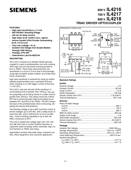
1-1469491-2 Product DetailsHome | Customer Support | Suppliers | Site Map | Privacy Policy | Browser Support© 2008 Tyco Electronics Corporation All Rights Reserved SearchProducts Documentation Resources My Account Customer SupportHome > Products > By Type > Two-Piece, High-Speed Connectors > Product Feature Selector > Product Details1-1469491-2Active MULTIGIG RT ProductAlways EU RoHS/ELV Compliant (Statement of Compliance)Product Highlights:?Pin, External Thread?Guidance Series?VITA 41/VITA 46 Configuration?Used With 9mm Guide ModuleView all Features | Find SimilarProductsCheck Pricing &AvailabilitySearch for ToolingProduct FeatureSelectorContact Us AboutThis ProductQuick LinksDocumentation & Additional InformationProduct Drawings:?KEYED GUIDE PIN, DIE CAST BACKPLANE CONNECTOR, MULTI...(PDF, English)Catalog Pages/Data Sheets:?Power Connectors & Interconnection Systems Catalog -...(PDF, English)?MULTIGIG RT Connector Products for VITA 46 (VPX) Sta...(PDF, English)Product Specifications:?None AvailableApplication Specifications:?None AvailableInstruction Sheets:?None AvailableCAD Files:?None AvailableList all Documents Additional Information:?Product Line InformationRelated Products:?ToolingProduct Features (Please use the Product Drawing for all design activity)Product Type Features:?Product Type = Pin, External Thread ?Finish = Silver?Comment = KeyedBody Related Features:?Series = Guidance?Used With = 9mm Guide Module?Pin Material = Zinc Alloy Industry Standards:?RoHS/ELV Compliance = RoHS compliant, ELVcompliant?Lead Free Solder Processes = Not relevant forlead free process?VITA 41/VITA 46 Configuration = Yes?RoHS/ELV Compliance History = Always wasRoHS compliantOther:?Brand = AMPProvide Website Feedback | Contact Customer Support。
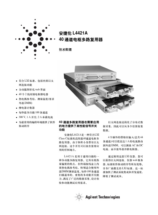
40通道多路复用器在需要应用的地方提供了高性能信号开关功能安捷伦L4421A 是一种符合LXI Class C 标准的高性能40通道电枢多路复用器。
由于体积小及带有以太网连接,这个开关可以放在需要应用的任何地方。
L4421A 是用于通用扫描的一种多功能多路复用器。
它具有低热量偏置的特点,在终端接线盒上内置热电偶参考结,特别适合使用外部DMM 测量温度。
每秒100条通道扫描速率的、密集的多功能开关能力,满足了广泛的数据采集、设计检验和功能测试应用需求。
安捷伦L4421A40通道电枢多路复用器技术数据以太网连接还简化了分布式数据采集,因此可以从多个位置收集数据。
4个额外的带熔丝输入(总共44条通道)可以把高达1 A 的电流路由到外部DMM ,可以测量AC 和DC 电流,而不需外部并联电阻器。
通过使用这部LXI 仪器,您可以获得以太网连接、仪器web 服务器、标准软件驱动程序等所有优势。
许多厂商都支持LXI 标准,这一标准加快了测试系统集成和开发速度,降低了测试成本。
符合LXI 标准,包括内置以太网连接功能全功能图形化web 界面40个2线闭锁电枢继电器热电偶参考结,测量温度(要求外部DMM)继电器计数器每秒最多扫描100条通道300 V, 1 A 开关; 2 A 承载电流为最常用的编程环境提供了软件驱动程序为灵活可靠的连接提供开关功能可以把多个不同点中的一个点连接到单点上,也可以创建拥有多条连接的自定义配置。
在配置为多路复用器时,L4421A带有先断后通连接,保证在扫描过程中不会有两个信号相互连接在一起。
序列功能定义了开关顺序,控制着复杂的信号路由,保证开关闭合顺序。
可以指配一个序列,指定名称,然后使用用户创建的自定义名称执行这个序列。
外部触发功能可以简便地定时和同步测量和其它事件,这有助于确定什么时候开始或结束采集。
L4421A还包括一个继电器计数器,监测及帮助预测什么时候继电器已经接近使用寿命。
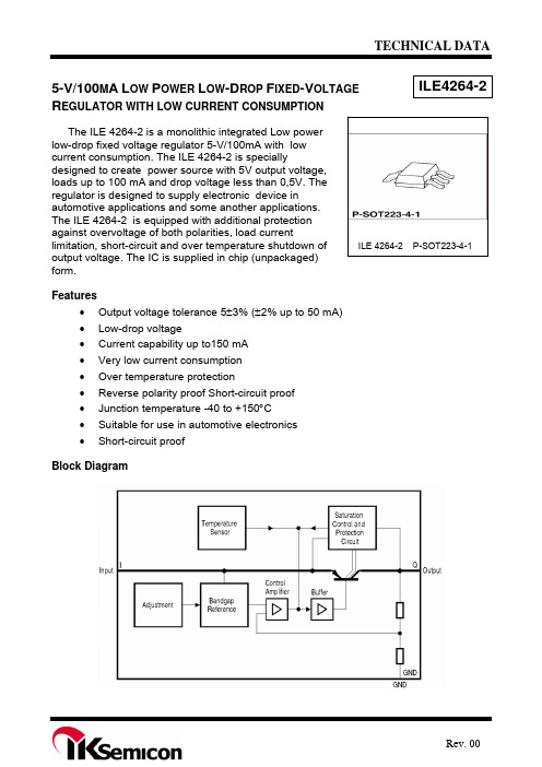
TECHNICAL DATAILE4264-25-V/100M A L OW P OWER L OW -D ROP F IXED -V OLTAGE R EGULATOR WITH LOW CURRENT CONSUMPTIONILE 4264-2 P-SOT223-4-1The ILE 4264-2 is a monolithic integrated Low power low-drop fixed voltage regulator 5-V/100mA with low current consumption. The ILE 4264-2 is speciallydesigned to create power source with 5V output voltage, loads up to 100 mA and drop voltage less than 0,5V. The regulator is designed to supply electronic device in automotive applications and some another applications. The ILE 4264-2 is equipped with additional protection against overvoltage of both polarities, load current limitation, short-circuit and over temperature shutdown ofoutput voltage. The IC is supplied in chip (unpackaged) form.Features• Output voltage tolerance 5±3% (±2% up to 50 mA) • Low-drop voltage• Current capability up to150 mA • Very low current consumption • Over temperature protection• Reverse polarity proof Short-circuit proof • Junction temperature -40 t о +150°С• Suitable for use in automotive electronics • Short-circuit proofBlock DiagramPin description (for P-SOT223-4 package)Pin Symbol Function 01 I Input voltage; block to ground directly with a ceramic capacitor 03 Q 5-V output voltage; block to ground with a capacitor 02, 04 GND GroundTypical electric parameters(U I =13,5 V, -40 o C ≤ T J ≤ 125 o C, unless specified otherwise)Parameter, unit of measurement Symbol Mode of measurement Typical valuePower Supply Ripple Rejection, dBPSRRf r = 100 Hz,U r = 3 V (peek-to-peek)68Absolute Maximum RatingsMaximum RatingsAbsolute MaximumRatingsParameter, symbolUnit Min Max Min MaxJunction temperature, ТJ oC -40* 125 -40* 150 Storage temperature, Тstg oC - - -50 150 Input voltage, U I V 6 28 -42 45Input current, I ImA - Internally limited - InternallylimitedGround pin current, I GND mA - - 50*** - Output voltage, U QV 4,9 5,1 -0,3*** 32*** Output current (pin 3), I QmA - Internally limited - InternallylimitedThermal ResistancesJunction-case , R th jc , for conventional case P-SOT223-4-1oC/W - 25** - 25**Thermal ResistancesJunction-ambient, R th ja , for conventional case P-SOT223-4-1, - without heat sinkoC/W-220** -220*** Ambient temperature** R th ja - Thermal Resistances Junction-ambient *** - Voltage is not applied to pin IThermal resistance junction ambient for IC with heat dissipater is calculated by formula:R th ja = R th jc + R th ca , (1)Rth jc - thermal resistance junction case, oC /W.Application circuit and heat dissipater have to provide T J ≤ 125 o С.Maximum power Ptot,Вт, dissipated by IC for TA , is calculated by formula:P tot = (125 - T A ) / R th ja , (2)125 – maximum permitable operating junction temperature, ОСElectric parameters (U I =13,5 V, -40 o C ≤ T J ≤ 125 o C, unless specified otherwise)Typical valueParameter, unit of measurementSymbol Mode of measurement Min MaxNote9 V ≤ U I ≤ 16 V 5 mA ≤ I Q ≤ 50 mA 4,9 5,1 Output voltage, VU Q6 V ≤ U I ≤ 21 V 5 mA ≤ I Q ≤ 100 mA 4,85 5,15 Maximum output current, mA I Qmax 4,8 V ≤ U Q ≤ 5,2 V 150 500 I Q =0,1 mA, (T J ≤ 85o C)- 0,06 I Q = 0,1 mA - 0,07 Consumption current, mA, I q = I I - I QI q I Q = 50 mA - 4 Drop-out voltage, V U Dr I Q = 100 mA - 0,5 1Load regulation, mV ΔU Q(I) 1 mA ≤ I Q ≤ 100 mAU I = 13,5 V - 90 Line regulation, mVΔU Q(U)6 V ≤ U I ≤ 28V I Q = 1 mA- 30Notes1 Drop voltage U Dr = U I - U Q (measured when the output voltage V Q has dropped 100 mV from the nominal value obtained at V I = 13.5 V).ILE4264-2 Application CircuitTypical Performance CharacteristicsPackage Dimensions P-SOT 223-4-1。
THS4271集成电路实验特性及其应用摘要:以TI公司生产的集成运放THS4271为基础搭建实验测试电路,在定义的条件下实验,分别测量了运放的输入失调电压UIO,输入失调电流IIO,共模抑制比CMRR,开环差模放大倍数AUd等主要参数。
同时对测量的数据对应的相应的参数进行了简单分析。
基于THS4271的单位增益稳定,低失真,高压摆率等特性,举出几个应用实例,来说明其在某些工程领域有一定的应用价值,供今后的使用者参考。
关键词:THS4271;集成运放;实验;应用虽然经过多年的发展,在现代集成电路与系统芯片(Systemon Chip,SoC)中,集成电路运算放大器的应用依然非常广泛,并往往由应用需要对其性能提出苛刻的要求。
因此围绕高性能集成电路运算放大器的研究经久不衰。
文中结合实际项目的需要,对THS4271集成运放的主要参数进行了测试,并对结果和其应用进行了讨论,利于今后实验的开展,同时为器件的使用者提供参考。
1 芯片介绍THS4271是TI公司生产的低噪声,高压摆率,单位增益稳定电压反馈放大器,其设计正常工作电压范围是5~15 V。
兼有低噪声,高压摆率,宽带宽,低失真以及单位增益稳定的特性,使得THS4271具有高性能的表现。
此放大器的使用者可以在一个较宽的频带上获得实验所需的较高的动态范围,而不必为放大器在失偿期间的稳定性担忧。
该系列的放大器的封装形式有SOIC,带有PowerPAD的MSOP,以及带PowerPAD无引线的MSOP。
THS4271典型特征参数如表1所示。
THS4271原件形状,引脚分布及各引脚功能如图1所示。
(其中NC代表悬空)2 实验原理2.1 输入失调电压理想运算放大器(简称运放)的输入信号为零时,其输出直流信号也应该为零。
但实际上如果没有外界的调零措施,由于运放内部参数不完全对称,输出电压往往不为零。
这种输入为零时输出不为零的现象称为集成运放的失调。
在室温和标准电源电压下,为了使输出端的直流电压为零,必须先在输入端加一个直流电压作为补偿电压,以抵消偏离零点的输出电压,而这个加在输入端的电压即被称为输入失调电压UIO。
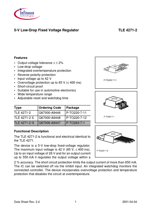
TECHNICAL DATA 5-V L OW-D ROP F IXED V OLTAGE R EGULATORILE4271-2Functional Descriptionvoltage of 26 V and for an output current up to 550 mA it regulatesprotection limits the output current of more than 650 mA.The IC can be switched off via the inhibit input. An integratedincorporates overvoltage protection and temperature protectionthat disables the circuit at unpermissibly high temperatures.Features•Output voltage tolerance ≤± 2%•Low-drop voltage•Integrated overtemperature protection•Reverse polarity protection•Input voltage up to 42 V•Overvoltage protection up to 65 V (≤ 400 ms)•Short-circuit proof•Suitable for use in automotive electronics•Wide temperature range•Adjustable reset and watchdog timePin Definitions and FunctionsPin Symbol Function1 I Input; block to ground directly on the IC with ceramic capacitor.Inhibit2 INH3 RO Reset Output; the open collector output is connected to the5 V output via an integrated resistor of 30 kOhmGround4 GND5 D Reset Delay; connect a capacitor to ground for delay time adjustment.Input6 WWatchdog7 Q 5-V Output; block to ground with 22 uF capacitor, ESR < 3 Ohm.Application DescriptionThe IC regulates an input voltage in the range of 5.5 V < V I < 36 V to V Qnom = 5.0 V. Up to 26 V it produces a regulated output current of more than 550 mA. Above 26 V the save-operating-area protection allows operation up to 36 V with a regulated output current of more than 300 mA. Overvoltage protection limits operation at 42 V. The overvoltage protection hysteresis restores operation if the input voltage has dropped below 36 V. The IC can be switched off via the inhibit input, which causes the quiescent current to drop below 50 uA. A reset signal is generated for an output voltage of VQ < 4.5 V. The watchdog circuit monitors a connected controller. If there is no positive-going edge at the watchdog input within a fixed time, the reset output is set to low. The delay for power-on reset and the maximum permitted watchdog-pulse period can be set externally with a capacitor.Design Notes for External ComponentsAn input capacitor CI is necessary for compensation of line influences. The resonant circuit consisting of lead inductance and input capacitance can be damped by a resistor of approx. 1 Ohm i n series with C I. An output capacitor CQ is necessary for the stability of the regulating circuit. Stability is guaranteed at values of C Q≤22 uF and an ESR of <3 Ohm.Circuit DescriptionThe control amplifier compares a reference voltage, which is kept highly accurate by resistance adjustment, to a voltage that is proportional to the output voltage and drives the base of a series transistor via a buffer. Saturation control as a function of the load current prevents any over-saturation of the power element.If the output voltage decreases below 4.5 V, an external capacitor CD on pin 4 (D) will be discharged by the reset generator. If the voltage on this capacitor VD drops below VDRL, a reset signal is generated on pin 2 (RO), i.e. reset output is set low. If the output voltage rises above 4.5 V, CD will be charged with constant current. After the power-on-reset time V D reaches V DU and the reset output will be set high again. The value of the power- on-reset time can be set within a wide range depending on the capacity of C D. The value of the pull-up resistor at reset output is typically 30 kOhm.After V D has reached the voltage V DU and reset was set to high, the watchdog circuit is enabled and discharges C D with a constant current. If there is no positive-going edge observed at watchdog input, C D will be discharged down to VDWL. Then reset will be set low and the watchdog circuit will be disabled. C D will be charged with the current as at power-on reset until V D reaches V DU and reset will be set high again.If a watchdog pulse will be observed before C D is discharged down to V DWL, the watchdog circuit will be enabled and CD will be charged too, but reset will not be set low. After V D has reached V DU, the periodical behavior starts again.The IC also incorporates a number of internal circuits for protection against:• Overload• Overvoltage• Overtemperature• Reverse polarityBlock DiagramMaximum & Absolute Maximum RatingsMaximum RatingsAbsolute MaximumRatingsParameter SymbolUnit min. max. min. max.Junction temperature, ТJ oC -40 125 -40 150 Storage temperature, ТS oC - - -50 150 - - - -Input voltage, V I V - - - -6 36 -42 42Inhibit voltage, U INH V - - - 65*Input current, I I A - internally limited - internallylimitedOutput voltage, U Q V 4,9 5,1 -1 16 Output current, I QmA -5 internally limited -5 internallylimitedCurrent on common pin ,I GND mA - - -0.5 – Reset voltage, U R V 4,9 5,1 -1 16 Reset current, I RA -5 internally limited -5 internallylimitedOutput voltage, U QV - - -0.3 7 Output current, I Q mA - - -5 5 Output voltage, U Q V - - -0.3 7 Output current, I QmA - - -5 5 Thermal resistance junction ambient (P-TO-263-7-1), R th ja ,oC /W - 70** - 70**Thermal resistance junction case (P-TO-263-7-1), R th jc °С/W - 3** - 3*** Time of influence t ≤ 400ms** Thermal resistance junction ambient for IC with heat dissipater is calculated by formula: R th ja = R th jc + R th ca (1)R th jc - thermal resistance junction case, o C /W.Application circuit and heat dissipater have to provide T J ≤ 125 ОС.Maximum power P tot ,Вт, dissipated by IC for T A , is calculated by formula: P tot = (125 - T A ) / R th ja (2)125 – maximum permitable operating junction temperature, ОС.Optimum reliability and life time are guaranteed if the junction temperature does notexceed 125 o C in operating mode. Operation at up to the maximum junction temperature of 150 o C is possible in principle. Note, however, that operation at the maximum permitted ratings could affect the reliability of the device.Operating RangeLimit ValuesParameter Symbol min. max. Unit NotesInput voltage VI 6 40 V –Junction temperature Tj – 40 150 oC – Thermal Resistance 65 K/W –Junction ambient Rthja – 70 K/W P-TO263Rthjc – 3 K/W –Junction case Zthjc – 2 K/W t <1 msCharacteristicsVI = 13.5 V; – 40 o C ≤T j ≤125 o C (unless otherwise specified)Limit ValuesParameter, unitSymbol Test ConditionMin. Max. Note6V ≤V I ≤26V;5mA ≤I Q ≤550mA4.905.10Output voltage, VV Q26V ≤V I ≤36V; I Q ≤300mA4.905.10 Output current limiting, mA I Qmax V Q =0В 650 Currentconsumption, мкА, I q = I II qV e =0В; I Q =0mA 50I Q =5mA 1,5 I Q =550mA 75 Currentconsumption, mA I q = I I - I QI Q =550mA; V I =5V 90 Drop voltage, VV DrI Q =550mA 0.7 3Load regulation, mV ∆V Q(I)5мА ≤ I Q ≤ 550mAV I = 6 V50 Supply voltage regulation, mV∆U Q(U)6B ≤ U I ≤ 26VI Q =5mA25Limit ValuesParameter, unitSymbol Test Condition Min. Max. Note InhibitInhibit ON voltage, V V INH,on U Q >4.5V 3,5 Inhibit OFF voltage, VV INH,offU Q <0.8V0,8Inhibit current, uA I INH U INH =5V 8 25 Overvoltage protectionНапряжение выключения, В V I, OV 40 46 WatchdogUpper timing threshold, V V DU 1.4 2.3 Lower watchdog timing threshold, VV DWL 0.2 0.8 Discharge current, uA I dis U D =1V 1.5 3.5 Charge current, uA I d U D =1V 8 25 Watchdog period, ms t w C D =100 nF 40 75 Watchdog trigger time, ms t wt C D =100 nF 30 66 Reset Generator Switching threshold, V V RT 4.5 4.8 Reset high voltage, V V ROH 4.5 - Reset low voltage, V V ROL I R =3mA, V Q = 4.4V - 400 Resistance of circuit, kOhm R Direct connection to pin Q18 46Lower reset timing threshold, VV DRL V Q < V RT0.2 0.8 Upper reset timing threshold, VV DU 1.4 2.3 Delay time, ms t d C D = 100 nF 8 18 Charge current, uA I d V D = 1.0 V 8 25Notes1 Following capacitances are connected: - on input C1I = 1000 uF(electrolytic), C2I = 470 nF - on output C Q = 22 uF (electrolytic).2 Measurements of parameters have to carry out with pulse equipment.3 Drop voltage V Dr = V I - V Q (measured when the output voltage has dropped 100 mV from the nominal value obtained at 13.5 V input)1)Test CircuitApplication CircuitTime ResponseTime Response, Watchdog BehaviorPackage Dimensions P-TO 220-7-180。