机械工程专业英语教程第三版lesson25
- 格式:doc
- 大小:31.00 KB
- 文档页数:5
《机械工程专业英语》词汇Chapter One Mechanics Components 第一章机械构件 Lesson One 第一课齿轮 Words and Expressions1.spur gear 直齿轮2.thermal expansion 热膨胀3.lubrication润滑4.backlash倾向间隙5.the pitch circles节圆6.space width间隙宽度7.instrument gear仪表齿轮8.the split gear拼合齿轮9.helical gear斜齿轮10.pitch-line velocities节线速度11.an axial thrust轴向推力12.blank 坯件13.double-helical gears 人字齿轮14.non-intersecting不相交的15.worm gears蜗轮蜗杆16.bevel gears伞齿轮17.crossed-axis交叉轴18.nut 螺母19.screw丝杠螺钉rge rations 大速比21.parallel-shaft gears平行轴齿轮22.single-thread worms单线蜗杆23.lead angles导角24.multiple-thread worms多线蜗杆25.hypoid gear偏轴伞齿轮26.rolling Cones滚锥27.involutes渐开线,Lesson Two Rolling Guides and Bearings 第二课滚动导轨和轴承Words and Expressions1.rolling guides (rolling guideways) 滚动导轨2.plain guides普通导轨3.a roller chain滚柱链4.cape保持架5.guide surfaces导轨面6.stiffness 刚性7.load-carrying capacity 载荷能力8.rolling-contact bearings滚动轴承9.ball bearing球轴承10.an inner race 内座圈11.an outer race外座圈12.separator 隔离环13.curvature曲率14.notch 凹槽15.thrust load 推力负载16.a radial ball bearing经向球轴承17.sections断面18.an axial-thrust bearing轴向推力轴承19.washer 垫圈20.roller bearing 滚子轴承21.tapered 锥形的22.spherical球面的23.retaining shoulder 定位肩24.needle bearing滚针轴承25.tapered roller bearings锥形滚子轴承26.spherical roller bearings 球面滚子轴承27.concave凹面的28.convex凸面的Lesson Three Clutches第三课离合器Word and Expressions1.coaxial (coaxial) 同轴的,共轴的2.a rotatable shaft (driven shaft) 从动轴3.a rotating shaft (driving shaft) 主动轴4.friction clutches磨擦离合器5.ring-shaped环形的6.spring弹簧7.a conical spool锥形短管轴8.coefficient of friction磨擦系数9.facing衬片10.dry clutches干式离合器11.wet clutches 湿式离合器12.a multiple-plate disc clutch多片式圆盘离合器13.spline花键14.pivot枢轴15.magnetic clutches电磁离合器16.an annular gap环状间隙17.powder iron铁粉18.graphite石墨19.direct-current control coil直流控制线圈20.slippage滑动Lesson Four Ball screw and nuts 第四课滚珠丝杠螺母副Words and Expressions1.precision ball screw assembly 精密滚珠丝杠副2.auto-drafting machines自动制图机3.valves阀门4.metallurgical machinery冶金机械5.satellite tracers卫星跟踪仪6.steering gears转向机构7.stick-slip 爬行循环8.rolling guideways滚动导轨9.recirculating-ball screw滚珠丝杠10. feed mechanisms 进给机构11. wear 磨损12. damping property 阻尼性13. tangential 切向的14. circumferential 圆周的15. thread pitch螺距16. a ball-return track回珠滚道17. a return tube回珠管18. shock-free无冲击19. stiffness刚性20. freedom from免除21. pre-load预载Chapter Two Constructure and Technology of Machine Tools第二章机床结构及工艺Lesson One Size, Bed and Tailstock of Engine lathe第一课普通车床的尺寸、床身及尾架Words and Expressionsthe (turning lathe, engine lathe, tuning machine) 车床2.the live center point 活顶尖3.swing 回转直径4.bed 床身5.ways导轨6.Carriage 床鞍7.Cross-feed slide 横进给刀架8.Headstock主轴箱9.tailstock. 尾架10. rack 齿条11. pinion gear小齿轮12. handwheel 手轮13. hardened steel 淬火钢14. flame-hardened ways 火焰淬火导轨15. the distance between centers项尖距16. taper shank锥形车削17. tailstock spindle 尾架锥柄18. taper shank 套筒19. three-jaw chuck三爪卡盘20. roller bearing滚子轴承21. lubrication润滑22. workpiece工件Lesson Two Headstock of Engine Lathe第二课普通车床的主轴箱Words and Expressions1.spindle 主轴2.taper sleeve锥套3.live center轴心活顶针4.the threaded spindle nose螺纹主轴头5.the cam lock spindle nose凸轮锁紧主轴头6.the long taper key drive spindle nose长锥键传动主轴头7.flange法兰盘8.Chuck卡盘9.Cam lock stud、凸轮锁紧短轴10. Collar 轴环11. faceplate套圈12. keyway花盘,键槽13. back gear背轮14. bull gear 大齿轮15. sliding pit滑动槽16. groove、槽17. step pulley塔轮18. drive pulley主动轮19. driven pulley被动轮20. gear box齿轮变速箱Lesson Three Carriage, Feeding and Threading Mechanism of Engine Lathe第三课普通车床的床鞍、进给和车螺纹机构 Words and Expressions1.Saddle鞍座2.Apron 滑板箱3.Cross slides 横向滑板,横刀架pound rest 复合刀架(转盘)5.tool post小刀架6.tool holder 刀夹7.Clutch 离合器8.Facing 车端面9.Cutoff 切断机动进给10. power feed 动力进给11. split nut (half-nut) 开合螺母12. dovetail way 燕尾导轨13. micrometer collar 千分尺套圈摇柄14. rocker 摇臂15. threading 车螺纹16. gear box 齿轮箱,传动箱17. ring collar 刻度环18. an index chart 指示图19. lead screw丝杠20. feed rod 光杠21. Cross-feed横进给22. Longitudinal feed 纵向进给23. acme threads 梯形螺纹24. right-hand thread右旋螺纹25. left-hand thread 左旋螺纹Lesson Four Word-holding attachments for the lathe and Rough turning第四课车床工件夹紧附件和粗车Words and Expressions1.attachment 附件2.four-jaw independent chuck 四爪单动卡盘3.Collar chuck 套爪卡片4.follower rest 跟刀架5.reducing sleeve 中心架the dog 异径套筒7.bent-tail dog 车床卡爪8.Rough turning 曲尾卡爪9.Rough turning粗车white lead白铅粉Center height中心高end副后角relief后角Clearance angle留隙角 back rake 纵向前角tangent切线caliper卡尺trial cut试切overload过载、Lesson Five Milling Shaper, Planer and Grinding Machines第五课铣床、刨床和磨床Words and Expressionsling machines 铣床ling cutter 铣刀刀杆3.arbor 心轴4.spacer 垫圈、垫片5.bushing套6.yoke 支座7.starting lever 起动手柄8.Knee升降台9.elevating screw 升降丝杆10. index head分度头11. foot stock 分度头支座12. Universal Milling Machine 万能铣床13. Shaper牛头刨床14. plane 龙门刨床15. ram 滑轨16. vise 台钳17. fixture 夹具18. notched wheel or ratchet 棘轮19. pawl 棘爪20. cross rail 横梁21. grinding machine 磨床22. grinding wheel 砂轮23. finish 光洁度24. Cutter grinder 工具磨床25.surface grinder 平面磨床26.centreless grinder 无心磨床27.internal grinder 内圆磨床28.external grinder 外圆磨床29.Wheel head磨头Lesson Six Machine Tool Tests, Accuracy checking and Maintenance 第六课机床试验,精度检验及保养Words and Expressions1.acceptance tests 验收试验2.certificate data 检验证数据3.geometrical accuracy几何精度4.surface roughness 表面粗糙度5.vibration-proof 防振6.straightness 平直度7.flatness 平面度8.upright立柱9.base plate 底板10. deviation 偏差11. parallelism 平行度12. squareness垂直度13. servicing 维修14. inspection检查15. repairs 检修16. maintenance 保养17. rapidly wearing components 易损件18. post-inspections repairs 后检查修理19. periodic repairs定期检修20. routine servicing 日常维修21. general overhaul 大修22. restoration修复Chapter Three Modern Manufacturing Engineering &Development第三章现代制造技术及其发展Lesson One The development of NC 第一课数字控制的发展 Words and Expressions1.vacuum tube 真空管2.electrical relay 继电器3.interface 接口4.integrated circuit(IC) 集成电路5.hardware 硬件6.Read Only Memory(ROM) 只读存储器7.Machining Center 加工中心8.Turning Center车削中心9.electrical discharge machining电火花加工10.drafting制图11.printed circuit(PC) 印刷电路12.robot机械手,机器人13.Subroutine子程序14.tape reading纸带读数15.alarm 报警16.diagnostic message诊断信息17.Constant surface speed control 恒线速控制18.polar coordinate 极座标19.interpolation插补20.microprocessor微处理机21.servo drive伺机服驱动22.pre-amplifier前置放大器23.point-to-point点位24.contouring轮廓控制25.bubble memory磁泡存储器26.macro宏指令27.canned cycle固定循环Lesson Two Open-loop and closed-loop servo drives第二课开环和闭环伺服驱动Words and Expressionsrmation command section 信息命令段2.punched tape code穿孔带码3.magnetic tape code 磁带码4. input data 输入数据5.open-loop开环6.closed-loop 闭环7.automatic washing machine自动洗衣机8.power supply level电源电平9.feedback 反馈10. resolution清晰度11. deterioration恶化,变坏12. discrepancy差误13. subtract logic减法逻辑14. command position counter 指令位置计数器15. drive signal amplifier 伺服信号放大器16. transducer 传感器17. synchro 同步机18. shaft digitizer轴数字读出器19. analog模拟量digital数字式self-correcting自动修正light interruption光中断photo cell光电管electric pulse电脉冲increment增量encoder编码器binary二进制Gray code格雷码Segmentation扇区Lesson Three Hydraulic motors and servo motors第三课液压马达和伺服电机Words and Expressions1.hydraulic motor 液压马达2.oil sump 油箱,油槽3.oil pressure pump 油压力泵4.hydraulic cylinder 液压缸5.valve 阀6.oil flow 油流7.hydrostatic drives 水力驱动,静压驱动8.variable-delivery pump9.piston 活塞10. reciprocating movement 往复运动11. supply line 供应线12. return line 回程线13. the filling cycle14. servomotors 伺服电机15. input command signals 输入命令符号16. step-by-step motors 步进电机17. Phase-shifted18. Amplifier 放大器19. Contact 触点,接头20. Electromagnet 电磁铁。
Lesson 1 力学的基本概念1、词汇:statics [stætiks] 静力学;dynamics动力学;constraint约束;magnetic [mæɡ'netik]有磁性的;external [eks'tə:nl] 外面的, 外部的;meshing啮合;follower从动件;magnitude ['mæɡnitju:d] 大小;intensity强度,应力;non-coincident [kəu'insidənt]不重合;parallel ['pærəlel]平行;intuitive 直观的;substance物质;proportional [prə'pɔ:ʃənəl]比例的;resist抵抗,对抗;celestial [si'lestjəl]天空的;product乘积;particle质点;elastic [i'læstik]弹性;deformed变形的;strain拉力;uniform全都相同的;velocity[vi'lɔsiti]速度;scalar['skeilə]标量;vector['vektə]矢量;displacement代替;momentum [məu'mentəm]动量;2、词组make up of由……组成;if not要不,不然;even through即使,纵然;Lesson 2 力和力的作用效果1、词汇:machine 机器;mechanism机构;movable活动的;given 规定的,给定的,已知的;perform执行;application 施用;produce引起,导致;stress压力;applied施加的;individual单独的;muscular ['mʌskjulə]]力臂;gravity[ɡrævti]重力;stretch伸展,拉紧,延伸;tensile[tensail]拉力;tension张力,拉力;squeeze挤;compressive 有压力的,压缩的;torsional扭转的;torque转矩;twist扭,转动;molecule [m likju:l]分子的;slide滑动; 滑行;slip滑,溜;one another 互相;shear剪切;independently独立地,自立地;beam梁;compress压;revolve (使)旋转;exert [iɡ'zə:t]用力,尽力,运用,发挥,施加;principle原则, 原理,准则,规范;spin使…旋转;screw螺丝钉;thread螺纹;2、词组a number of 许多;deal with 涉及,处理;result from由什么引起;prevent from阻止,防止;tends to 朝某个方向;in combination结合;fly apart飞散;3、译文:任何机器或机构的研究表明每一种机构都是由许多可动的零件组成。
Lesson 2 Carbon and Alloy SteelTEXTSteel is probably the most widely used material for machine elements because of its properties of high strength, high stiffness, durability and relative ease of fabrication. The term steel refers to and alloy of iron, carbon, manganese and one or more other significant elements. Carbon has a very strong effect on the strength, hardness and ductility of any steel alloy. The other elements affect hardenability, toughness, corrosion resistance, machinability and strength retention at high temperatures. The primary alloying elements present in the various alloy steels are sulfur, phosphorus, silicon, nickel, chromium, molybdenum and vanadium.1.Importance of CarbonAlthough most steel alloys contain less than 1.0% carbon, it is included in the designation because of its effect on the properties of steel. As Figure 1.2illustrates, the last tow digits indicate carbon content n hundredths of a percent.As carbon content increases, strength and hardness also increase under the same conditions of processing and heat treatment. Since ductility decreases withincreasing carbon content, selecting suitable steel involves some compromisebetween strength and ductility.As a rough classification scheme, a low-carbon steel is one having fewer than30 points of carbon (0.30%). These steels have relatively low strength but goodformability. In machine element applications where high strength is not required, low-carbon steels are frequently specified. If wear is a potential problem,low-carbon steels can be carburized to increase the carbon content in the veryouter surface of the part and to improve the combination of properties.Medium-carbon steels contain 30 to 50 points of carbon (0.30%-0.50%).Most machine elements having moderate to high strength requirements withfairly good ductility and moderate hardness requirements come from this group.High-carbon steels have 50 to 95 points of carbon (0.50%-0.95%). The high carbon content provides better wear properties suitable for applications requiringdurable cutting edges and for applications where surfaces are subjected to constant abrasion. Tools, knives, chisels, and many agricultural implement components are among these uses.2.Stainless SteelsThe term stainless steel characterizes the high level of corrosion resistance. To be classified as a stainless steel, the alloy must have a chromium content of at least 10%. Most have 12% to 18% chromium.The three main groups of stainless steels are austenitic, ferritic, and martensitic. Austenitic stainless steels fall into the AISI 200 and 300 series. They are general-purpose grades with moderate strength. Most are not heat-treatable, and their final properties are determined by the amount of working. These alloys are nonmagnetic and are typically used in food processing equipment.Ferritic stainless steels belong to the AISI 400 series, designated as 405, 409, 430, 446, and so on. They are magnetic and perform well at elevated temperatures, from 1300℉to 1900℉(700℃-1040℃). They are notheat-treatable, but they can be cold-worked to improve properties. Typical applications include heat exchanger tubing, petroleum refining equipment, automotive trim, furnace parts, and chemical equipment.Martensitic stainless steels are also members of the AISI 400 series, including 403, 410, 414, 416, 420, 431 and 440 types. They are magnetic, can be heat-treated, and have higher strength than the AISI 200 and 300 series, while retaining good toughness. Typical uses include turbine engine parts, cutlery, scissors, pump parts, valve parts, surgical instruments, aircraft fittings, and marine hardware.3.Structural SteelsMost structural steels are designated by ASTM numbers established by American Society for Testing and Materials. The most common grade is ASTMA36, which has a minimum yield point of 36000 psi (248MPa) and is very ductile. It is basically a low-carbon, hot-rolled steel available in sheet, plate, bar, and structural shapes, such as wide-flange beams, American standard beams, channelsand angles.Most wide-flange beams are currently made using ASTM A992 structural steel, which has a yield point of 50 ksi to 65 ksi and a minimum tensile strength of 65 ksi. An additional requirement is that the maximum ratio of the yield point to the tensile strength is 0.85. This is a highly ductile steel, having a minimum of 21% elongation in a 2.00-inch gage length. Using this steel instead of the lower strength ASTM A36 steel typically allows smaller, lighter structural members at little or no additional cost.Hollow structural sections (HSS) are typically made from ASTM A500 steel that is cold-formed and either welded or made seamless. Included are round tubes and square rectangular shapes. There are different strength grades can bespecified. Some of these HSS products are made from ASTM A501 hot-formed steel having properties similar to the ASTM A36 hot-rolled steel.Many higher-strength grades of structural steel are available for use in construction, vehicular, and machine applications. They provide yield points in the range from 42 000 psi to 10 000 psi (290 MPa-700MPa).4.Tool SteelsTool steels refers to a group of steels typically used for cutting tools, punches, dies, shearing blades, chisels and similar uses. The numerous varieties of toolsteel materials have been classified into seven general types. Whereas most uses of tool steels are related to the field of manufacturing engineering, they are also pertinent to machine design where the ability to maintain a keen edge underabrasive conditions is required. Also, some tool steels have rather high shockresistance which may be desirable in machine components such as parts formechanical clutches, pawls, blades, guides for moving materials and clamps.READING MATERIALThe final properties of steels are dramatically affected by the way the steels are produced. Some processes involve mechanical working, such as rolling toa particular shape or drawing through the dies. In machine design, many bar-shaped parts, shafts, wire and structural members are produced in these ways. But most machine parts, particularly those carrying heavy loads, are heat-treated to produce high strength with acceptable toughness and ductility.Carbon steel bar and sheet forms are usually delivered in the as-rolling condition, that is, they are rolled at an elevated temperature that eases the rolling process. The rolling can also be done cold to improve strength and surface finish. Cold-drawn bar and wire have the highest strength of the forms, along with a very good surface finish. However, when a material is designated to be as-rolled, it should be assumed that it was hot-rolled.1.Heat TreatingHeat treating is the process in which steel is modified its properties by different elevated temperatures. Of the several processes available, those most used for machine steels are annealing, normalizing, through-hardening (quench and temper), and case hardening.Figure 1.3 shows the temperature-time cycles for these heat treating processes. The symbol RT indicates normal room temperature, and LC refers to the lower critical temperature at which the ferrite transformation begins during the heating of the steel. At the upper critical temperature (UC), the transformation is complete. These temperatures vary with the composition of the steel. For most medium-carbon (0.30%—0.50%) steels. UC is approximately 1 500°F(822℃). References giving detailed heat treating process data should be consulted.1)AnnealingFull annealing (Figure 1.3(a)) is performed by heating the steel above the upper critical temperature and holding it until the composition is uniform. Then the steel is cooled very slowly in the furnace until its temperature is below the lower critical temperature. Slow cooling to room temperature outside the furnace completes the process. This treatment produces a soft, low-strength form of the material, free of significant internal stresses. Parts are frequentlycold-formed or machined in the annealed condition.Stress relief annealing (Figure 1.3 (b)) is often used following welding, machining, or cold forming to relieve residual stresses and thereby minimize subsequent distortion. The steel is heated to approximately 1 000 °F to 1 200 °℉(540℃—650℃), held to achieve uniformity, and then slowly cooled in still air to room temperature.NormalizingNormalizing (Figure 1.3 (c)) is similar to annealing, but at a higher temperature, above the transformation range where austenite is formed, approximately 1 600 ℉(870℃). The result is a uniform internal structure in the steel and somewhat higher strength than annealing produces. Machinability and toughness are usually improved over the as-rolled condition.2.Through-Hardening and Quenching and TemperingThrough-hardening (Figure 1.3(d)) is accomplished by heating the steel to above the transformation range where austenite forms and then rapidly cooling it in a quenching medium. The rapid cooling causes the formation of martensite, the hard and strong form of steel. The properties of the martensite forms depend on the alloy’s composition. An alloy containing a minim um of 80% of its structure in the martensite form over the entire cross section has high hardenability. This is an important property to look for when selecting a requiring high strength and hardness steel. The common quenching media are water, brine, and special mineral oils. The selection of a quenching medium depends on the required cooling rate. Most machine steels use either oil or water quenching.Tempering is usually performed immediately after quenching and involves reheating the steel from a temperature of 400℉to 1 300℉(200℃—700℃) and then slowly cooling it in air to room temperature. This process modifies the steel’s properties. Tensile strength and yield strength decrease with increasing tempering temperature, whereas ductility improves, as indicated by an increase in the percent elongation. Thus, the designer can tailor the propertiesof the steel to meet specific requirements. Furthermore, the steel in its as-quenched condition has high internal stresses and is usually quite brittle. Machine parts should normally be tempered at 700 ℉(370℃) or higher after quenching.(a)full annealing (b) stress relief annealing(c) normalizing (d) quenching and tempering(through-hardening)Figure 1. 3 Heat treatments for steels3. Case HardeningIn many cases, many parts require only moderate strength although the durface must have a very high hardness. In gear teeth, for example, high surface hardness is necessary to resist wearing as the mating teeth come into contact several million times during the expected life of the gears. At each contact, a high stress happens at the surface of the teeth. In this condition, case hardening is used. The surface (or case) of the part is given a high hardness to a depth of perhaps 0.010 in to 0.040 in (0.25 mm—1.00 mm), although the interior of the part (the core) is affected only slightly, if at all. Theadvantage of surface hardening is that as the surface receives the required wear-resisting hardness, the core of the part remains in a more ductile form which is resistant to impact and fatigue. The most used processes of case hardening are flame hardening, induction hardening, carburizing, nitriding, cyaniding, carbo-nitriding.。
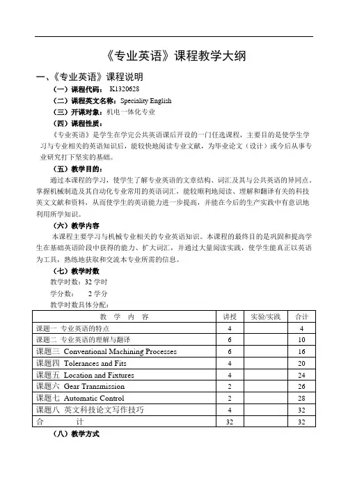
《专业英语》课程教学大纲一、《专业英语》课程说明(一)课程代码:K1320628(二)课程英文名称:Speciality English(三)开课对象:机电一体化专业(四)课程性质:《专业英语》是学生在学完公共英语课后开设的一门任选课程,主要目的是使学生学习与专业相关的英语知识后,能较快地阅读专业文献,为毕业论文(设计)或今后从事专业研究打下坚实的基础。
(五)教学目的:通过本课程的学习,使学生了解专业英语的文章结构、词汇及其与公共英语的异同点。
掌握机械制造及其自动化专业常用的英语词汇,能较顺利地阅读、理解和翻译有关的科技英文文献和资料,从而使学生的英语能力进一步提高,并能在今后的生产实践中有意识地利用所学知识。
(六)教学内容本课程主要学习与机械专业相关的专业英语知识。
本课程的最终目的是巩固和提高学生在基础英语阶段中获得的能力、扩大词汇,并通过大量阅读实践,使学生能真正以英语为工具,熟练地获取和交流本专业所需的信息。
(七)教学时数教学时数:32学时学分数:2学分(八)教学方式以黑板+多媒体教学手段为主,以学生自学、讨论、练习为辅的教学方式。
(九)考核方式和成绩记载说明考核方式为开卷考试。
严格考核学生出勤情况,达到学籍管理规定的旷课量取消考试资格。
综合成绩根据平时成绩和期末成绩评定。
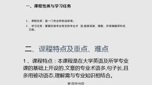
二、讲授大纲与各章的基本要求课题一专业英语的特点教学要点:通过本课题内容的教学,使学生了解并熟悉机械工程专业英语的词汇特点、语法特点以及修辞特点等相关知识,为专业英语材料的阅读理解打下基础。
教学时数:4学时教学内容:1. 专业英语的意义与功用2. 专业英语的常见词汇特点3. 专业英语的常见语法特点4. 专业英语的修辞特点考核要求:1、了解专业英语的意义与功用(熟悉);2、了解专业英语词汇的组成特点(领会)3、认识专业英语的语法及修辞特征(领会)课题二专业英语的理解与翻译教学要点:通过本课题内容的教学,使学生了解翻译的基本方式,熟悉典型语法现象的翻译技巧,初步熟悉机械工程专业英语的词汇及语法翻译技巧。
机械工程专业英语》参考译文高等学校机械设计制造及其自动化专业新编系列教材(供教师及学生使用)黄运尧黄威司徒忠李翠琼武汉理工大学出版社目录编译者的话………………………………第1章材料和热加工…………………第1课机械学的基本概念…………第2课塑性理论的基本假设………第3课有限元优化的应用…………第4课金属…………………………第5课金属和非金属材料…………第6课塑料和其他材料……………第7课模具的寿命和失效…………第8踩冷加工和热加工……………第9踩铸造…………………………第10课制造中的金属成形工艺…第11课缎选………………………第12课锻造的优点和工作原理…第13课焊接………………………第14课热处理……………………第二章机构和机器原理……………。
第15课机构介绍…………………。
第16课运动分析………………….第l7课运动的综合………………—第18课凸轮和齿轮………………—第19课螺纹件,紧固件和联接件—第20课减(耐)摩擦轴承…………*第2l课斜齿轮、蜗杆蜗轮和锥齿轮第22课轴、离合器和制动器……—第三章机床………第23课机床基础第24课车床……第25课牛头刨、钻床和铣床…………第36课磨床和特种金属加工工艺……第四章切削技术和液压“………………第27课加工基础………………………第28课基本的机械加工参数…………第29课切削参数的改变对温度的影响第30课刀具的磨损…………第31课表面稍整加工机理…第32课极限和公差…………“第33课尺寸控制和表面桔整”第34课自动央具设计………“第36课变速液压装置……………—…………—策37课电液伺服系统…………。
……………。
第五章机械电子技术………………………………第38课专家系统……。
…………………………第3D课建筑机器人………………………………第40课微机为基础的机器人模拟………………第41课机器人学的定义和机器入系统…………第42课微型计算机基础(1)……………………第43课微型计算机基础(x)……………………第44课可编程控制器……………………………第45课CAD/CAM计算机辅助设计与制造…第46课计算机数控和直接数控,CNC和DNC第47课加工过程的数控—………………………第48课柔性制造系统……………—……………第仍课交互式编程系统…………………………第50课在振动分析方面的计算机技术…………策51课压力传感器………………………………第52课反馈元件…………………—……………第53课现代按制理论概述………………………第54课管理上采取了新的措施—来自福持汽第六章英文科技文献和专利文献的查阅…………6.1 常见科技文献及其查阅………………………6.2 专利文献概述…………………………………第七章英文科拉论文写作…………………………7.1 标题与摘要写法………………………………7.2 正文(body)的组织与写法…………………7.3 致谢、附录及参考文献………………—……参考文献………………………………………………第1章材料和热加工机械学的基本概念功是力乘以该力作用在物体上佼物体移动的距离。
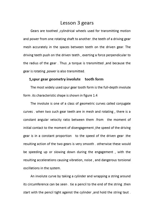
Lesson 3 gearsGears are toothed ,cylindrical wheels used for transmitting motion and power from one rotating shaft to another .the teeth of a driving gear mesh accurately in the spaces between teeth on the driven gear. The driving teeth push on the driven teeth , exerting a force perpendicular to the radius of the gear . Thus ,a torque is transmitted ,and because the gear is rotating ,power is also transmitted.1,spur gear geometry involute tooth formThe most widely used spur gear tooth form is the full-depth involute form .its characteristic shape is shown in figure 1.4The involute is one of a class of geometric curves called conjugate curves . when two such gear teeth are in mesh and rotating , there is a constant angular velocity ratio between them .from the moment of initial contact to the moment of disengagement ,the speed of the driving gear is in a constant proportion to the speed of the driven gear .the resulting action of the two gears is very smooth . otherwise these would be speeding up or slowing down during the engagement , with the resulting accelerations causing vibration, noise , and dangerous torsional oscillations in the system.An involute curve by taking a cylinder and wrapping a string around its circumference can be seen . tie a pencil to the end of the string .then start with the pencil tight against the cylinder ,and hold the string taut .move the pencil away from the cylinder while keeping the string taut . the curve drawed is an involuteThe circle represented by the cylinder is called the base circle . notice that at any position on the curve , the string represents a line tangent to the base circle and ,at the same time , perpendicular to the involute . drawing another base circle along the same centerline in such a position that the resulting involute is tangent to the first one ,it demonstrates that at the point of contact, the two lines tangent to the base circles are coincident and will stay in the same position as the base circles rotate . this is what happens when two gear teeth are in mesh .It is a fundamental principle of kinematics, the study of motion, that if the line drawn perpendicular to the surfaces of two rotating bodies at the point of contact always crosses the centerline between the two bodies at the same place , the angular velocity ratio of the two bodies will be constant . this is a statement of gearing .as demonstrated here ,the gear teeth made in the involute-tooth form obey the law.2,helical gear geometryHelical and spur gears are distinguished by the orientation of their teeth .on spur gears ,the teeth are straight and are aligned with the axis of the gear .on helical gears , the teeth are inclined at an angle with the axis, that angle being called the helix angle. If the gear was very wide ,it would appear that the teeth wind around the gear blank in acontinuous , helical path . however , practical considerations limit the width of the gears so that the teeth normally appear to be merely inclined with respect to the axis .figure 1.5 shows two examples of commercially available helical gears.The form of helical gear teeth are very similar to those discussed for spur gears . the basic task is to account for the effect of the helix angle .3,helix angleThe helix for a given gear can be either left-hand or right-hand . the teeth of a right-hand helical gear would appear to lean to the right when the gear is lying on a flat surface . conversely , the teeth of a left-hand helical gear would lean to the left . in normal installation , helical gears would be mounted on parallel shafts . to achieve this arrangement ,it is required that one gear should be of the right-hand design and that the other be left-hand with an equal helix angle .if both gears in mesh are of the same hand ,the shafts will be at 90 degrees to each other . such gears are called crossed helical gears.The parallel shaft arrangement for helical gears is preferred because it results in a much higher power-transmitting capacity for a given size of gear than the crossed helical arrangement .The main advantage of helical gears over spur gears is smoother engagement because a given tooth assumes its load gradually instead of suddenly .contact starts at one end of a tooth near the tip andprogresses across the face in a path downward across the pitch line to the lower flank of the tooth , where it leaves engagement .simultaneously , other teeth are coming into engagement before a given tooth leaves engagement , with the result that a larger average number of teeth are engaged and are sharing the applied loads compared with a spur gear . the lower average load per tooth allows a greater power transmission capacity for a given size of gear , or a smaller gear can be designed to carry the same power .The main disadvantage of helical gears is that an axial thrust load is produced as a natural result of the inclined arrangement of the teeth. The bearings that hold the shaft carrying the helical gear must be capable of reacting against the thrust load.Reading materialTypes of gearsSeveral kinds of gears having different tooth geometries are in common use . the acquaint you with the general appearance of some , their basic descriptions are given here .Spur gears have teeth that are straight and arranged parallel to the axis of the shaft that carries the gear . the curved shape of the faces of the spur gear teeth has a special geometry called an involute curve . this shape makes it possible for two gears to operate together with smooth,positive transmission of power .The teeth of helical gears are arranged so that they lie at an angle with respect to the axis of the shaft . the angle ,called the helix angle ,can be virtually any angle . typical helix angle range from approximately 10 to 30 ,but angles up to 45 are practical .the helical teeth operate more smoothly than equivalent spur gear teeth ,and stresses are lower. Therefore ,a smaller helical gear can be designed for a given power-transmitting capacity than a spur gear. One of the disadvantages of helical gears is that an axial force , called a thrust force ,is generated in addition to the driving force that acts tangent to the basic cylinder on which the teeth are arranged . the designer must consider the thrust force when selecting bearing that will hold the shaft during operation . shafts carrying helical gears are typically arranged parallel to each other .however ,a special design ,called crossed helical gears ,has 45 helix angles, and the shafts operate 90 to each other .Bevel gears have teeth that are arranged as elements on the surface of cone . the teeth of straight bevel gears appear to be similar to spur gear teeth ,but they are tapered , being wider at the outside and narrower at the top of the cone ,bevel gears typically operate on shafts that are 90 to each other .indeed ,this is often the reason for specifying bevel gears in a drive system ,specially designed bevel gears can operate on shafts that are at some angel other than 90. When bevelgears are made with teeth that form a helix angle similar to that in helical gears , they are called spiral bevel gears. They operate more smoothly than straight bevel gears and can be made smaller for a given power transmission capacity . when both bevel gears in a pair have the same number of teeth ,they are called miter gears and are used only to change the axes of the shaft to 90 degrees . no speed change occurs .A rack is a straight gear that moves linearly instead of rotating . when a circular gear is mated with a rack , the combination is called a rack and pinion drive . you may have heart that term applied to the steering mechanism of a car or to a part of other machinery .A worm and its mating worm gear operate on shafts that are at90 degrees to each other . they typically accomplish a rather large speed reduction ratio compared with other types of gears . the worm is the driver ,and the worm gear is the driven gear. The teeth on the worm appear similar to screw threads, and , indeed , they are often called threads rather than teeth . the teeth of the worm gear can be straight like spur gear teeth ,or they can be helical. Often the shape of the tip of the worm gear teeth is enlarged to partially wrap around the threads of the worm to improve the power transmission capacity of the set . one disadvantage of the worm / worm gear drive is that it has a somewhat lower mechanical efficiency than most other kinds of gears because there is extension rubbing contact between the surfaces of the wormthreads and the sides of the worm gear teeth.Think of examples of gears in actual equipment . describe the operation of the equipment , particularly the power transmission system . sometimes ,of course ,the gears and the shafts are enclosed in housing , making it difficult for you to observe the actual gears. Perhaps you can find a manual for the equipment that shows the drive system. Try to answer the following questions:(1)What was the source of the power ,an electric motor, a gasolineengine , a steam turbine , or a hydraulic motor ?were the gears operated by hand?(2)How were the gears arranged together, and how were they attachedto the driving source and the driven machine?(3)Was there a speed change ? can you determine how much of achange ?(4)Were there more than two gears operated by hand ?(5)What types of gears were used?(6)What materials were gears made from ?(7)How were the gears attached to the shafts that supported them ?(8)Were the shafts for mating gears aligned parallel to each other ,orwere they perpendicular to one another ?(9)How were the shafts themselves supported ?(10)Was the gear transmission system enclosed in housing?。
机械五班王乘龙Lesson 25 Computer Graphics(Reading Material)The term computer graphics refers to the entire spectrum of drawing with the aid of a computer,from straight lines to color animation.An immense range of artistic capabilities resides under the heading of computer graphics and drafting is just one of them.Computer graphics was originally associated with the field of electronics.Companies directly involved in electronics design and manufacturing were the first to experiment and work with computer graphics.As they tested equipment and software,new demands arose that required changes and advances in both hardware and software.Equipment and programs got better,faster,more powerful,less expensive,colorful,and fun to operate.The potential for this new computer development was endless.And as engineers and drafters learned to work with the new tools in a technically demanding atmosphere,artists were using the new tools in an atmosphere of unlimited structure.We see the structure and freedom brought by engineers and artists to computer graphics as we watch animated television network.Complex mathematicalcalculations are combined with the creative eye of the artist to achieve effects unseen just a few years ago.The world of computer graphics is a dynamic and,at times,volatile filed. The developments in technique and equipment have advanced rapidly,and the areas of application continue to spread. The drafting applications of CAD are unlimited The speed-of-light capabilities of the computer have shaped the gathering,processing,storage,and retrieval of information into a major industry.Every day our lives are touched by the effects of computers.Contrary to science-fiction works of years past,computers have not grown to occupy the core of the earth,but have shrunk to microscopic proportions,and now occupy tiny spaces inside our machines and tools.The tools of the drafting trade have also felt the electronic touch of computers.The silicon chip has found its way into drafting tools.The heart of modern drafting tools is now the computer.The traditional tools of graphics,such as the T-square,compass,and drafting machines(Fig.25.1)are rapidly becoming obsolete.Now the drafter,or operator,uses electronic hardware to construct drawings,not onpaper,but on what looks like a television screen.The screen is called a monitor,video display screen,or video display terminal(VDT).The drafting process is now called computer-aided design drafting.or CADD.Most people say “computer-aided drafting’’and use the acronym of CAD.Actually,CAD means computer-aided designThe first commercially produced computer drafting system was introduced by IBM in puter drafting systems began to mature and prove themselves in the late 1970s.Sales of computer graphics that time there has been an terminals reached approximately exponential increase in the sales twenty thousand in 1979.Since that time there has been an exponential increase in the sales of computer graphics systems.A visit to your local industries and engineering firms will make you aware of the popularity of computer-aided drafting.But why is it so popular? Why were computers introduced as the:tool to replace the drafting machine and pencil? Why are companies scrambling to convert to computer drafting?Foremost in your mind must be the fact that we live in the global market economyenvironment which thrives on innovation and competition.We are always trying to outdo each other and discover new ways to make money.New technology,such as using a computer,often gives the competitive edge to one company over another.The new electronic technology has given some company an advantage because of a couple of characteristics of the computer that are not possessed by most humans.Computers are extremely fast.The contents of an entire encyclopedia can be transmitted in a fraction of a second.Computers are accurate.Each of these characteristics helps people increase productivity. which is the key to the success of using computer graphics.Without an increase in productivity it is doubtful that computer graphics would have ever gained as much popularity as it has.But a fast machine cannot account for the productivity gain by itself;it needs competent human operators.The computer may be fast,but it cannot think,make judgments,nor reason.Human,on the other hand,may be slow,but they are intelligent and can use their power of reasoning to solve problems and overcome obstacles。
机械五班王乘龙Lesson 25 Computer Graphics(Reading Material)The term computer graphics refers to the entire spectrum of drawing with the aid of a computer,from straight lines to color animation.An immense range of artistic capabilities resides under the heading of computer graphics and drafting is just one of them.Computer graphics was originally associated with the field of electronics.Companies directly involved in electronics design and manufacturing were the first to experiment and work with computer graphics.As they tested equipment and software,new demands arose that required changes and advances in both hardware and software.Equipment and programs got better,faster,more powerful,less expensive,colorful,and fun to operate.The potential for this new computer development was endless.And as engineers and drafters learned to work with the new tools in a technically demanding atmosphere,artists were using the new tools in an atmosphere of unlimited structure.We see the structure and freedom brought by engineers and artists to computer graphics as we watch animated television network.Complex mathematicalcalculations are combined with the creative eye of the artist to achieve effects unseen just a few years ago. The world of computer graphics is a dynamic and,at times,volatile filed. The developments in technique and equipment have advanced rapidly,and the areas of application continue to spread. The drafting applications of CAD are unlimited The speed-of-light capabilities of the computer have shaped the gathering,processing,storage,and retrieval of information into a major industry.Every day our lives are touched by the effects of computers.Contrary to science-fiction works of years past,computers have not grown to occupy the core of the earth,but have shrunk to microscopic proportions,and now occupy tiny spaces inside our machines and tools.The tools of the drafting trade have also felt the electronic touch of computers.The silicon chip has found its way into drafting tools.The heart of modern drafting tools is now the computer.The traditional tools of graphics,such as the T-square,compass,and drafting machines(Fig.25.1)are rapidly becoming obsolete.Now the drafter,or operator,uses electronic hardware to construct drawings,not on paper,but on what looks likea television screen.The screen is called a monitor,video display screen,or video display terminal(VDT).The drafting process is now called computer-aided design drafting.or CADD.Most people say“computer-aided drafting’’and use the acronym of CAD.Actually,CAD means computer-aided design The first commercially produced computer drafting system was introduced by IBM in puter drafting systems began to mature and prove themselves in the late 1970s.Sales of computer graphics that time there has been an terminals reached approximately exponential increase in the sales twenty thousand in 1979.Since that time there has been an exponential increase in the sales of computer graphics systems.A visit to your local industries and engineering firms will make you aware of the popularity of computer-aided drafting.But why is it so popular? Why were computers introduced as the:tool to replace the drafting machine and pencil? Why are companies scrambling to convert to computer drafting?Foremost in your mind must be the fact that we livein the global market economyenvironment which thrives on innovation and competition.We are always trying to outdo each other and discover new ways to make money.New technology,such as using a computer,often gives the competitive edge to one company over another.The new electronic technology has given some company an advantage because of a couple of characteristics of the computer that are not possessed by most humans.Computers are extremely fast.The contents of an entire encyclopedia can be transmitted in a fraction of a second.Computers are accurate.Each of these characteristics helps people increase productivity. which is the key to the success of using computer graphics.Without an increase in productivity it is doubtful that computer graphics would have ever gained as much popularity as it has.But a fast machine cannot account for the productivity gain by itself;it needs competent human operators.The computer may be fast,but it cannot think,make judgments,nor reason.Human,on the other hand,may be slow,but they are intelligent and can use theirpower of reasoning to solve problems and overcome obstacles。