ABB NOCH 滤波器选型手册
- 格式:pdf
- 大小:107.36 KB
- 文档页数:12
中北大学课程设计说明书学生XX:朱燕梅学号:0805014102学院:信息与通信工程学院专业:电子信息科学与技术题目:滤波器变换指导教师:李永红职称:讲师2011 年6 月25 日中北大学课程设计任务书2010/2011 学年第二学期学院:信息与通信工程学院专业:电子信息科学与技术学生姓名:朱燕梅学号:0805014102 课程设计题目:滤波器变换起迄日期: 6 月13 日~6 月24 日课程设计地点:中北大学指导教师:李永红系主任:程耀瑜下达任务书日期: 2011 年 6 月13 日课程设计任务书课程设计任务书目录摘要10一、数字滤波器11一、1 数字滤波器的基本概念11一、2 数字滤波器的分类12一、3 数字滤波器的MATLAB实现13二、双线性变换法13二、1 双线性变换法知识简介13二、2 双线性变换法设计数字滤波器原理14三、设计任务及方案选择15三、1 设计任务与要求15三、2 方案设计16四、程序设计与调试18四、1 程序设计与说明18四、2 仿真结果与分析19五、心得体会21参考文献21摘要数字滤波器是数字信号处理的基础,用来对信号进行过滤、检测与参数估计等处理,在通信、图像、语音、雷达等许多领域都有着十分广泛的应用。
尤其在图像处理、数据压缩等方面取得了令人瞩目的进展和成就。
鉴于此,数字滤波器的设计就显得尤为重要。
此报告重点介绍了用双线性不变法设计IIR数字滤波器的基本流程,比较了各种设计方法的优缺点,总结了模拟滤波器的性能特征。
最后以双线性不变法设计了一个高通巴特沃斯FIR数字滤波器,介绍了设计步骤,然后在Matlab环境下进行了仿真与调试,实现了设计目标。
关键字:数字滤波器MATLAB 双线性一、数字滤波器一、1 数字滤波器的基本概念数字滤波器是数字信号处理的重要基础,是对信号都是过滤检测与参数估计等处理过程中,它是使用最为广泛的一种线性系统。
数字滤波器处理的对象是经由采样期间将模拟信号转换而得到的数字信号。

High Voltage Surge ArrestersBuyer´s Guide — Section HS PEXLIM T-TZinc-Oxide Surge Arrester HS PEXLIM T-TProtection of switchgear, transformers and other equipment in high voltage systems against atmospheric and switching overvoltages.−in areas with very high lightning intensity−where grounding or shielding conditions are poor or incomplete−for important installations−where energy requirements are very high (e.g. very long lines, capacitor protection).−Specially suited to extreme seismic zones.Superior where low weight, non-fragility and additional personnel safety is required.Other data can be ordered on request. Pleasecontact your local sales representative.Brief performance dataSystem voltages (U m)245 - 800 kVRated voltages (U r)180 - 624 kV Nominal discharge current (IEC)10/15/20 kA peak Classifying current (ANSI/IEEE)10/15 kA peakDischarge current withstand strength:High current 4/10 µsLow current 2000 µs100 kA peak2200 A peakEnergy capability:Line discharge class (IEC)[2 impulses, (IEC Cl. 8.5.5)Fulfils/exceeds requirements of ANSI transmission-line discharge test for 362 kV systems.Class 515.4 kJ/kV (U r)]Short-circuit/Pressure relief capability65 kA symExternal insulation Fulfils/exceedsstandardsMechanical strength:Specified long-term load (SLL)Specified short-term load (SSL)19000 Nm28000 NmService conditions:Ambient temperatureDesign altitudeFrequency-50 °C to +45 °Cmax. 1000 m15 - 62 HzABB Surge Arresters — Buyer´s Guide | Technical information 71HS PEXLIM T-T Guaranteed protective dataMax. system voltage RatedvoltageMax. continuousoperating voltage 1)TOV capability 2)Max. residual voltage with current waveas perIECas perANSI/IEEE30/60 µs8/20 µsU m kV rms U rkV rmsU ckV rmsMCOVkV rms1 skV rms10 skV rms1 kAkV peak2 kAkV peak3 kAkV peak5 kAkV peak10 kAkV peak20 kAkV peak40 kAkV peak245180144144209198354364371389405438476 192154154218207369380387406423457497 216156174246233415427435457476514559 228156180259246438451459482502542590 300228182182259246438451459482502542590 240191191273258461475484507528571621 362258206209310293523538548575599647704 264211212310293523538548575599647704 276221221314297531546556583608656714 380288230230328310554569580609634685745 400300240240342323577593604634660713776 420330264267378358638656669702731789859 360267291410388692712725761792856931 3902673154444207507717868248589271013 5503963173184744487938168318729089811072 4203363364784538078308468889249981091 44434935350647985387889493897710601153 800On requestMore detailed information on the TOV capability and the protective characteristics are given in Publ. 1HSM 9543 13-01en.1) The continuous operating voltages U c (as per IEC) and MCOV (as per ANSI) differ only due to deviations in type test procedures.U c has to be considered only when the actual system voltage is higher than the tabulated.Any arrester with U c higher than or equal to the actual system voltage divided by √3 can be selected.2) With prior duty equal to the maximum single-impulse energy stress (10.0 kJ/kV (U r)).Arresters with lower or higher rated voltages may be available on request for special applications.72 Technical information | ABB Surge Arresters — Buyer´s GuideMax. system voltage RatedvoltageHousing CreepagedistancemmExternal insulation *)DimensionsU m kV rms U rkV rms1.2/50 µsdrykV peak50 Hzwet (60s)kV rms60 Hzwet (10s)kV rms250/2500 µswetkV peakMasskgA maxmmBmmCmmDmmFig.245180-216TH245695010815245107501702310600-3001 228TV2459900150070070010502453495600-3002 300228-240TV30099001500700700105026034951600100010003 362258-276TH36299001500700700105026534951600100010003 380288TH38099001500700700105027034951600100010003 400300TM40099001500700700105027034951600100010003 420330TH420119001831874860127530040351600100010003 360TH42011900183187486012753004035120010006003390TV4201390021621048102015003304575120010006003 550396TH55014300216210481020150035048902000100012004 420TH55014300216210481020150035048902000100012004444TH55014850225010501050157540555402000100012005*) Sum of withstand voltages for empty units of arrester.ABB Surge Arresters — Buyer´s Guide | Technical information 7374 Technical information | ABB Surge Arresters — Buyer´s GuideFigure 1Figure 2Figure 4Figure 5Line terminals1HSA410 000-AAluminium1HSA410 000-B Aluminium flag with other items in stainless steel1HSA410 000-CAluminium1HSA410 000-DStainless steel Earth terminals1HSA420 000-UStainless steel1HSA420 000-VStainless steelDrilling plansWithout insulating baseAluminiumInsulating base1HSA430 000-PGalvanized steelM20 bolts for connection tostructure are not supplied by ABB.HS PEXLIM T-TAccessoriesABB Surge Arresters — Buyer´s Guide | Technical information 7576 Technical information | ABB Surge Arresters — Buyer´s GuideRated voltage Housing Number of arresters per crate One Three Six U r kV rms Volume m 3Gross kg Volume m 3Gross kg Volume m 3Gross kg 180TH245 5.4315 5.4676 6.01262192TH245 5.4316 5.4680 6.01270216TH245 5.4321 5.4692 6.01295228TV245 2.6340 4.3893--228TV300 2.8405 5.31006--240TV300 2.8407 5.31011--258TH362 2.8411 5.31026--264TH362 2.8411 5.31026--276TH362 2.8412 5.31028--288TH380 2.8414 5.31033--300TM400 2.8416 5.31038--330TH420 5.8507 6.61163--360TH420 5.2452 5.51086--390TV420 5.2483 5.51179--396TH550 6.7611 6.71355--420TH550 6.76126.71357--HS PEXLIM T-TShipping dataEach crate contains a certain number of arrester units and accessories for assembly and erection. A packing list is at-tached externally on each crate.Each separate crate is numbered and the numbers of all crates and their contents are listed in the shipping specifica-tion. ABB reserves the right to pack arresters in the most effective/economic combination. Alternate or non-standard crates may involve additional charges.The table above is to be seen as an approximation and specific data for deliveries may differ from the values given.Rated voltage HousingNumber of arresters per crate One Two U r kV rms Volume m 3Gross kg Volume m 3Gross kg 444TH550 3.76025.51054S e c t i o n o f 1H S M 9543 12-00e n H i g h V o l t a g e S u r g e A r r e s t e r s B u y e r ´s G u i d e , E d i t i o n 9.1, 2012-02For more information please contact:ABB ABHigh Voltage Products Surge ArrestersSE-771 80 Ludvika, Sweden Phone: +46 (0)240 78 20 00 Fax: +46 (0)240 179 83E-Mail:********************.com/arrestersonline©Copyright 2012 ABBAll rights reservedNOTE: ABB AB works continuously with product improvements. We therefore reserve the right to change designs, dimensions and data without prior notice.。
滤波器设置原则及相关计算滤波器是一种常见的信号处理工具,通过对输入信号进行滤波以提取所需信息或去除干扰噪声。
在实际的应用中,滤波器的设置原则和相关计算十分重要,正确的设置可以有效地提高滤波器的性能,进而提高系统的整体性能。
滤波器的设置原则:1.确定滤波器类型:根据所需的滤波效果,选择合适的滤波器类型,如低通、高通、带通、带阻等。
2.选择滤波器参数:根据信号的频率、幅度等特征选择滤波器参数,如截止频率、带宽、阻带范围等,以满足所需的滤波效果。
3.确定滤波器阶数:滤波器的阶数是指滤波器中反馈环和前向通路的数量,阶数越高,滤波器的效果越好,但同时也会带来更多的计算复杂度和延迟。
4.根据系统实际情况确定滤波器的输入和输出阻抗:滤波器的输入输出阻抗需要匹配系统的实际情况,在滤波器与其他部分连接时,应该将阻抗进行匹配以提高系统的整体性能。
滤波器的相关计算:1.计算滤波器的理论传递函数:滤波器的理论传递函数可通过计算系统的差分方程得到,根据系统的阶数、截止频率等参数进行计算,得到滤波器的理论传递函数。
2.计算滤波器的实际传递函数:实际上,制造和设计的滤波器在实际应用中存在着误差和偏差,因此需要通过实验或仿真等方式,得到滤波器的实际传递函数,以验证滤波器是否满足预期效果。
3.计算滤波器的群延迟:滤波器引入的群延迟会导致信号的相位变化,影响系统的整体性能,因此需要计算滤波器的群延迟,并尽可能地减小群延迟。
4.根据设计要求计算滤波器的阻抗、带宽等参数:根据所需的滤波效果,计算合适的阻抗、带宽、截止频率等参数,以满足设计要求。
总之,滤波器的设置原则和相关计算需要综合考虑滤波器的类型、参数、阶数、输入输出阻抗以及实际应用情况,经过合理的设计和计算,可以有效地提高滤波器的性能,从而提高系统的整体性能。
在使用滤波器的过程中,除了设置原则和相关计算以外,还需要进行一系列的优化和调试,以满足应用实际需求。
滤波器的优化和调试:1.选择合适的滤波器结构:滤波器的结构会影响滤波器的效果和计算复杂度,可以根据实际需求选择合适的结构,如IIR(无限冲激响应)滤波器、FIR(有限冲激响应)滤波器、卷积神经网络滤波器等。
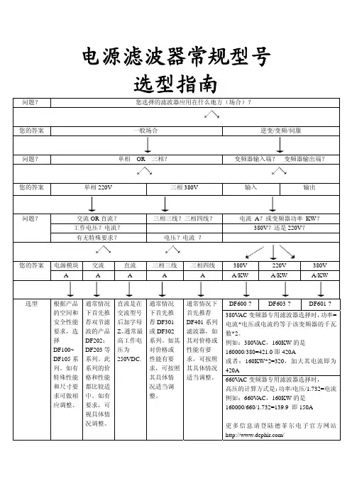
防干扰滤波器的选型标准
选择防干扰滤波器时,需要考虑多个因素,包括但不限于以下几点:
1. 频率范围,首先要确定需要滤波的信号频率范围,以便选择合适的滤波器类型和截止频率。
不同的应用可能需要不同的频率范围,例如,无线通信领域可能需要考虑到不同频段的信号干扰。
2. 滤波器类型,根据具体的应用需求,需要选择合适的滤波器类型,比如低通滤波器、高通滤波器、带通滤波器或带阻滤波器。
每种类型的滤波器都有其特定的特性和适用范围。
3. 插损和衰减,在选择滤波器时,需要考虑其插入损耗和信号衰减特性。
通常情况下,需要在滤除干扰的同时尽量减小对所需信号的影响,因此需要平衡插损和衰减的关系。
4. 尺寸和重量,针对不同的应用场景,尺寸和重量可能是一个考虑因素。
比如在航空航天领域或便携设备中,可能需要尽量减小滤波器的尺寸和重量。
5. 环境要求,某些特殊环境下,如高温、低温、高湿度等,滤波器的工作稳定性和可靠性也是需要考虑的因素。
6. 成本和可获得性,最后,成本和可获得性也是选择滤波器时需要考虑的因素。
要根据项目预算和市场供应情况综合考虑。
总的来说,选择防干扰滤波器的标准包括频率范围、滤波器类型、插损和衰减、尺寸和重量、环境要求以及成本和可获得性等多个方面,需要综合考虑各种因素来做出合适的选择。
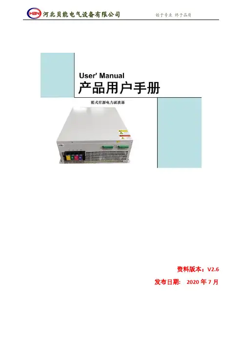
发布日期:2020年7月警告!只有授权的专业工程师才能安装、检修本装置;本产品的使用和日常维护必须由专业的电气人员进行,并且必须严格遵循用户手册中的安装程序和安全规程。
警告!设备检修时,设备断电后10分钟才能打开柜门,等设备内部电容放电完毕后方可进行检修。
警告!本设备运行时禁止更改设置,任何修改都必须在有源滤波器停止时进行,并警告!本设备大负荷运行时将产生大量的热量,必须保证通风良好。
警告!本设备必须可靠接地。
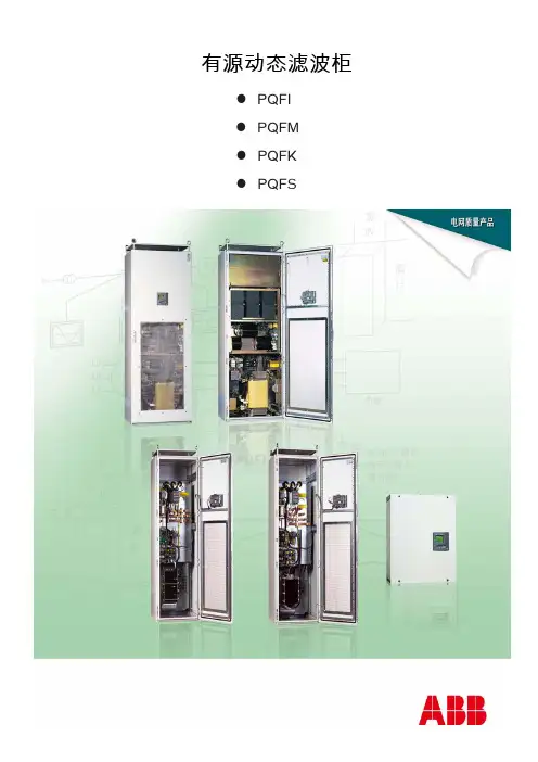
一、概述 (4)1.1产品概述 (4)1.2应用领域 (5)1.3满足的标准 (6)1.4产品型号 (7)1.5技术参数 (7)二、运输及储存 (9)2.1运输 (9)2.2储存 (9)三、安装 (9)3.1机械安装 (9)3.2电气安装 (12)四、运行及操作步骤 (19)4.1开机步骤 (19)4.2关机步骤 (19)五、操作控制显示面板 (19)5.1运行状态 (19)5.2故障列表 (21)5.3参数设置 (22)5.4电容补偿设置(非智能电容) (24)六、维护及常见问题 (25)6.1维护 (25)6.2常见问题 (25)一、概述1.1产品概述有源电力滤波器(Active Power Filter,简称APF),是采用现代电力电子技术和基于高速DSP器件的数字信号处理技术制成的新型电力谐波治理专用设备。
它由指令电流运算电路和补偿电流发生电路两个主要部分组成。
指令电流运算电路将外部互感器检测到电流信号转换为数字信号,送入高速数字信号处理器(DSP)对信号进行处理,将谐波与基波分离,并以脉宽调制(PWM)信号形式向补偿电流发生电路送出驱动脉冲,驱动IGBT或IPM功率模块,生成与电网谐波电流幅值相等、极性相反的补偿电流注入电网,对谐波电流进行补偿或抵消,实现主动消除电力谐波。
本系列有源电力滤波器是利用全控电力电子元件满足对电能质量(功率因数和谐波)有高级别要求的用户需求的装置。
APF装置并联在用电系统母线上,其主要功能是在电网供电过程中当负载侧产生谐波和无功电流时,对该电流进行补偿,减少系统侧谐波电流和无功电流,改善电能质量,使用户其他关键敏感设备得以在近似不受干扰的电气环境中正常运行,并且不会污染上级电网。
滤波器的分类与选型实战经验总结滤波器(filter),是一种用来消除干扰杂讯的器件,将输入或输出经过过滤而得到纯净的直流电。
对特定频率的频点或该频点以外的频率进行有效滤除的电路,就是滤波器,其功能就是得到一个特定频率或消除一个特定频率。
滤波器选型电路设计人员如何确定在哪种场合该选用哪种滤波器呢?本文旨在帮助他们作出这种决定。
滤波器的选择看似神秘,但实质上并非如此。
不过在很多场合,即使竭尽全力采取以下所述方法来选择,也还是需要实验多个滤波器后才能挑出最合适的一只。
那么,为什么要煞费苦心去正确的选择滤波器呢?按这里提供的准则来进行滤波器的筛选,至少可满足滤波器的正确尺寸和类型的要求,因此,试用滤波器仅仅是用一只滤波器替换另一只滤波器,同时检查传导及辐射发射,看哪只滤波器具有最佳的费效比。
如果在设计过程中没有足够的耐心去选择滤波器,墨菲法则(好象所有的物理、医疗和财政方面的公式都是从这里派生出来的)表明:最终证明是最合适的滤波器会与产品的其它要求完全不兼容。
要么滤波器太大或太重而不能安装在铸塑模机壳内,需要一笔昂贵的重新制造模具的费用,要么需要一种不易实现的安装方法,要么由于滤波器的泄漏电流,将使推向市场的产品存在安全隐患问题。
确实,如果没有仔细选择正确型号及类型的滤波器,那么按照墨菲法则,挑选合适的滤波器将增加研发和生产费用,同时也会推迟产品的上市时间。
1. 滤波器有关指标的计算通过将产品的发射频谱与相关的电磁兼容标准比较,可以估算用滤波器控制发射所需要的衰减量。
对于抗扰性控制,可以通过比较外部电噪声(通常取自有关的电磁兼容抗扰度标准)与产品电子线路的敏感性以及干扰期间希望达到的性能等级来估算一个粗略值。
当明确知道一个产品实际的发射或敏感性能时,就可采取精确的计算而不去进行估测。
不过,如果不是在一个可控的50Ω阻抗环境中工作,在购买滤波器时,厂家提供的产品指标是靠不住的。
2. 阻抗问题滤波器的工作原理是在射频电磁波的传输路径上形成很大的特性阻抗不连续,将射频电磁波中的大部分能量反射回源处。
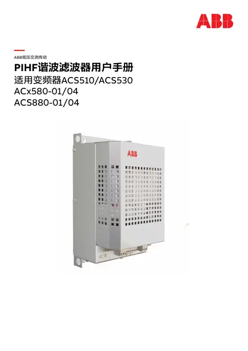
—ABB低压交流传动PIHF谐波滤波器用户手册适用变频器ACS510/ACS530 ACx580-01/04ACS880-01/04—相关手册列表变频器手册与指南编号(英文)编号(中文)ACS510 变频器用户手册(1.1...132 kW)3ABD000171993ABD00016170 ACS530 变频器硬件手册3AXD500000354003AXD50000035399 ACS530 标准控制程序固件手册3AXD500000354023AXD50000035401 ACS580-01 变频器硬件手册3AXD500000197383AXD50000018826 ACS580 标准控制程序固件手册3AXD500000160973AXD50000016430 ACS580-04 传动模块硬件手册3AXD500000154973AXD50000016428 ACH580 标准固件手册3AXD500000275373ABD00045445 ACH580-01 变频器硬件手册3AUA00000763313ABD00045444 ACH580-04 传动模块硬件手册3AXD500000486853ABD00046059 ACQ580 标准固件手册3AXD500000358673ABD00045443 ACQ580-01 变频器硬件手册3AXD500000358663ABD00045442 ACQ580-04 传动模块硬件手册3AXD500000486773ABD00046061 ACS880-01 硬件手册3AUA00000780933AXD50000009104 ACS880-04 硬件手册3AUA00001283013AXD50000023005 ACS880 基本控制程序固件手册3AUA00000859673AXD50000009105工具及维护手册与指南Drive composer PC工具用户手册3AUA0000094606@ 2021北京ABB电气传动系统有限公司3ABD00045569 Rev DZH生效日期:2021-02-01目录 3目录1. 手册介绍2. 安全须知本章内容 . . . . . . . . . . . . . . . . . . . . . . . . . . . . . . . . . . . . . . . . . . . . . . . . . . . . . . . . . . . . . . . . . . . . . . . . . . 5安装和维护安全. . . . . . . . . . . . . . . . . . . . . . . . . . . . . . . . . . . . . . . . . . . . . . . . . . . . . . . . . . . . . . . . . . . . . 5 3. 滤波器安装调试指导本章内容 . . . . . . . . . . . . . . . . . . . . . . . . . . . . . . . . . . . . . . . . . . . . . . . . . . . . . . . . . . . . . . . . . . . . . . . . . . .7产品概览. . . . . . . . . . . . . . . . . . . . . . . . . . . . . . . . . . . . . . . . . . . . . . . . . . . . . . . . . . . . . . . . . . . . . . . . . . . .7机械安装 . . . . . . . . . . . . . . . . . . . . . . . . . . . . . . . . . . . . . . . . . . . . . . . . . . . . . . . . . . . . . . . . . . . . . . . . . .10电气连接. . . . . . . . . . . . . . . . . . . . . . . . . . . . . . . . . . . . . . . . . . . . . . . . . . . . . . . . . . . . . . . . . . . . . . . . . . .11型号信息. . . . . . . . . . . . . . . . . . . . . . . . . . . . . . . . . . . . . . . . . . . . . . . . . . . . . . . . . . . . . . . . . . . . . . . . . . .13技术数据. . . . . . . . . . . . . . . . . . . . . . . . . . . . . . . . . . . . . . . . . . . . . . . . . . . . . . . . . . . . . . . . . . . . . . . . . . .15更多信息服务查询 . . . . . . . . . . . . . . . . . . . . . . . . . . . . . . . . . . . . . . . . . . . . . . . . . . . . . . . . . . . . . . . . . . . . . . . . . .21产品培训 . . . . . . . . . . . . . . . . . . . . . . . . . . . . . . . . . . . . . . . . . . . . . . . . . . . . . . . . . . . . . . . . . . . . . . . . . .214 目录安全须知 51安全须知本章内容本章介绍了对谐波滤波器单元进行安装、运行和维护时必须遵守的安全指导。
EJQ 29.12.1998MarkoVen?l?inenMatti LaitinenE 1 / 12Effective: 29.12.98ACS600 DU/DT FILTER SELECTION GUIDEOutput voltage of ACS6002Peak voltage and du/dt at the motor terminals 2Voltage vaweform3Applicable motors according to the service life of the insulation system 5Random wound motors 5Form wound motors 5du/dt filters6The enclosure class of the filters6A guide for adding the filter option to an Acknowledgement of Order 6Notes on installation of du/dt filter KITs 7Standard applications 7Other applications 9Pull-out torque with du/dt filter 11EMC 12CE12Bearing currents12APPENDIX 1: du/dt Filter Installation Guide12EJQ 29.12.1998MarkoVen?l?inenMatti LaitinenE 2 / 12Effective: 29.12.98Output voltage of ACS600Peak voltage and du/dt at the motor terminalsThe output voltage waveform of an inverter creates voltage spikes at the motor terminals in excess to dc-bus voltage. The combination of these voltage spikes and high du/dt-value of IGBT inverter output means additional stresses to motor insulation. This may shorten the life of the motor.In the graphs below the peak value ?LL and the rate of change du/dt of the voltage mesured at the motor terminals are seen as a function of the motor cable length. ?LL is scaled to nominal line-to-line voltage U LLnom . The scale of du/dt is kV/µs.The values of the graphs are typical values measured for ACS600 feeding a nominal load (Udc ?1.35* U LLnom ) to a rated motor. In case of regenerating or braking the value of ?LL is appr. 20 %higher.The values seen in the first graph are mesured without any output filtering. In the second graph the values are measured with the du/dt filter available for ACS600.Graph 1. ?LL/ U LLnom and du/dt at the motor terminals without outputfiltering as a function of motor cable length.EJQ 29.12.1998MarkoVen?l?inenMatti LaitinenE3 / 12Effective: 29.12.98Graph 2. ?LL/ U LLnom and du/dt at the motor terminals with du/dt filters.Voltage vaweformSome examples of measurements of the voltage at the motor terminals are shown below.U LLnom =690Vai:No output filtering & 30m motor cables.aii:No output filtering & 330m motor cables.bi:du/dt filters & 30m motor cables.bii:du/dt filters & 330m motor cables.EJQ 29.12.1998MarkoVen?l?inenMatti LaitinenE 4 / 12Effective: 29.12.98a i a ia iia iiFig. 1. Measurements without output filtering.b ib ib iib iiEJQ 29.12.1998MarkoVen?l?inenMatti LaitinenE 5 / 12Effective: 29.12.98Fig. 2. Measurements with du/dt filterApplicable motors according to the service life of the insulation systemThe motor cabability to withstand the additional stresses depends on the winding technique and insulation system used. When choosing a motor, the motor manufacturer should be consulted to find out whether the motor can be used directly or with du/dt filters. This is important especially in the case of implementing ACS600 to an existing installation. The motor used with ACS 600 must fulfill the following requirements cathegorized by the nominal mains voltage. (Given ?LLw and rise time* (∆t) values are the minimum withstand values of the motor insulation system. In general, the maximum ?LL and du/dt do not occur simultaneously as can be seen in the graphs 1 and 2 of the previous chapter).Random wound motors U LLnom ϒ 420 V ?LLw 3 1300 V.420 V < U LLnom ϒ 500 V?LLw 3 1300 V and du/dt Filter or?LLw 3 1600 V and ∆t ϒ 0.2 µs.500 V < U LLnom ϒ 600 V ?LLw 3 1600 V and du/dt Filter.600 V < U LLnom ϒ 690 V?LLw 3 1800 V and du/dt Filter.Form wound motors U LLnom ϒ 690 VInsulation system that fulfill ?LLw 3 2000 V and ∆t ϒ 0.3 µs can be used without du/dt filter.* Rise time (∆t) is defined as the interval, during which the voltage changes from 10% to 90% of the whole voltage range ∆u. Ref. eg. ¡°G u i de f o r app li ca t on o f cage i nducti on m o t o rs w hen fe from converters (revison of IEC 34-17)¡±, 2/938/CDVEJQ 29.12.1998MarkoVen?l?inenMatti LaitinenE 6 / 12Effective: 29.12.98du/dt filtersThere are two types of filters for ACS600: three-phase filters (NOCH0016-6X ... NOCH0070-6X)and single phase filters ( NOCH0120-6X...NOCH0400-6X ). The filters are designed to be cooled by natural convection. Three phase units are wall mounted and single phase types floor mounted unit. For mechanical dimension, see du/dt Filter Installation Guide.The enclosure class of the filtersThe last character of the du/dt Filter Type Code describes the enclosure class. The availableenclosure classes for each filter type are given in the table 1 below.Table 1.Example 1.NOCH0070-60enclosure class IP00A guide for adding the filter option to an Acknowledgement of Order ACS601 & ACS604For ACS601 and ACS604 the du/dt Filter option is external and must be ordered separately with the appropriate enclosure class.Example 1.001ACS60100206XXXXX2XX9XXX 1 pcs 002NOCH0030-60 KIT1 pcsExample 2.EJQ 29.12.1998MarkoVen?l?inenMatti LaitinenE 7 / 12Effective: 29.12.98001ACS60401206XXXXX2XX9XXX 1 pcs 002NOCH0120-60 KIT1 pcsKIT includes 1 three phase filter or 3 single phase filters plus du/dt Filter Installation Guide in a packaging box..ACS607For ACS607 the du/dt Filter option is internal and is added to the Type Code by choosing 5for the 20th character of Type Code. The enclosure class comes with the chosen enclosure class of the cabin.Example 3.001ACS60707606XXXXX2XX 5XXXNotes on installation of du/dt filter KITsWhen installing du/dt filter KITs, the following must be noted:ϒ The filters are designed to be cooled by natural convection.ϒ Free air flow must be arranged. 300 mm of free space must be left above, below (wall mounted types), left, right, front and back (floor mounted types) of the filter. Minimum 50 mm must be left between the single phase filters of a KIT.ϒ When installing a filter below an inverter unit, minimum 500mm free space must be left under the unit.ϒ For IP22 and IP54 filters, the maximum temperature rise of the enclosure surface is 40ϒ.ϒ Maximum cable length between the inverter and the filter is 3 m.ϒ IP00 filters must be enclosed by the customer to meet the local safety requirements.S tandard applications A n appropriate du/dt filter for standard applications for I N current can be chosen with the aid of table 1.EJQ 29.12.1998MarkoVen?l?inenMatti LaitinenE 8 / 12Effective: 29.12.98T able 1.A n appropriate du/dt filter for I NSQ current can be chosen with the aid of table 2. Note that the filter type in table 2 is not necessarily the same as the factory installed type in ACS607 (Table 1). In ACS607 the factory installed du/dt filter is mainly dimensioned for I N and I HD -currents. However,in ACS607 types 0100-3, 0140-3, 0170-3, 0260-3, 0120-5, 0170-5, 0210-5 and 0320-5 the factory installed du/dt filter can also be used with I NSQ current. See Table 2.T able 2.EJQ 29.12.1998MarkoVen?l?inenMatti LaitinenE 9 / 12Effective: 29.12.98N otes and limitations:ϒ du/dt filters are needed to protect the motor insulation because of the reasons explainedabove.ϒ Maximum motor cable lengths:NOCH0016-6X ... NOCH0070-6X :150 m (IP00, IP22) (300 m two filters in series) 50 m(IP54)(100 m two filters in series)NOCH0120-6X ... NOCH0400-6X :300 mϒ The cable length is cumulative in case of parallel connected motors.ϒ No restrictions to the cable types.ϒ Maximum output frequency is 120 Hz.ϒ For information on maximum cable lengths of inverters, see ACS600 Technical Catalogue .O ther applicationsF or other applications filters are chosen by the maximum thermal current Ith and the maximum energy E = ?C(U dc )2 according to table 3 below. The maximum losses per filterare also given in the table. I th:Total rms current of the filter.C :Total capacitance of the motor cable(s). ( Capacitance / length given in the cablecatalogue times the cumulative length of the motor cables ).U dc :Average dc-bus voltage.T able 3.EJQ 29.12.1998MarkoVen?l?inenMatti LaitinenE 10 / 12Effective: 29.12.98E xample 1.ϒ Three motors in parallel.ϒ 100 m MCMK 3x25+16; C = 0,45 µF / km;Ith1 = 62 A ϒ 150 m MCMK 3x25+16; C = 0,45 µF / km;Ith2 = 62 A ϒ 100 m MCMK 3X50+16; C = 0,6 µF / km;Ith3 = 91 AΤC = 0,250 x 0,45 µF + 0,1 x 0,6 µF = 173 nFIth = 215 Aϒ U = 510 VΤ Udc ? 1.35 x 510V = 689 V Τ E = 41 mJΤNOCH0260-60 KITN otes and limitations:ϒ Long-distance mode must be chosen.ϒ Maximum output frequency is 120 Hz.ϒ Maximum switching frequency is 2 kHzϒ Each separate cable (1-phase or 3-phase) is taken into account, when calculating the cumulative length of the motor cable(s).ϒ Above + 40ϒ C, the thermal current must be decreased 3.5% for every additional 1ϒC (up to + 50 ϒ C).ϒ For information on maximum cable lengths of inverters, see ACS600 Technical Catalogue .ϒ For other applications please contact ABB Industry for application design.EJQ 29.12.1998MarkoVen?l?inenMatti LaitinenE 11 / 12Effective: 29.12.98Pull-out torque with du/dt filterdu/dt filter is based on reactors and creates an additional voltage drop to the output voltage. The voltage drop decreases the pull-out torque. The decrease can be estimated by the following formula:T TN L L LkTTN L Lk =+====σσσpull -out torque with filter pull -out torque without filter motor transient inductance reactor phase inductanceAn adequate approximation of transient inductance is the sum of stator leakage inductance and rotor leakage inductance referred to stator.RsL σsLmL σr 'Rr ' / sU / ? 3σσσσσL L s L r L s L r ?+=='' ; transient inductance stator leakage inductancerotor leakage inductance referred to stator For reactor phase inductances see the table 4. belowdu/dt filter Lk / µHdu/dt filter Lk / µHNOCH0016-6X 150NOCH0120-6X 92NOCH0030-6X 140NOCH0260-6X 74NOCH0070-6X115NOCH0400-6X52Table 4.EJQ 29.12.1998MarkoVen?l?inenMatti LaitinenE 12 / 12Effective: 29.12.98Note:With long motor cables, the decrease of pull-out torque due to cable resistance and inductance is usually more important than that of caused by the filter.EMCWhen used together with ACS600, du/dt filters comply with relevant EMC standards. Additonally,du/dt filter decreases capacitive leakage currents and high frequency emission of the motor cable as well as high frequency losses at the motor.CEThe CE marking indicates that the product works in conformity with the directives that are valid for the product. The CE marking of du/dt filters indicates that the product works in conformity with the Low Voltage Directive and EMC Directive.Bearing currentsSingle phase du/dt filters ( NOCH0120-6X ... NOCH0400-6X ) effectively damp the bearing currents. For more information about the bearing currents refer to High frequency bearing currents in low voltage asynchronous motors. / ABB Industry Oy & ABB Motors OyAPPENDIX 1:du/dt Filter Installation Guide 3AFY 58933368。
滤波器设计.1滤波器概述1.1概念滤波器通常是一种能使某些频率的信号通过而同时抑制或衰减另外一些频率的信号的电子装置。
通过的频率范围(频带)成为通带,通带内输出信号的幅度比较大,在理想情况下为一恒定数值。
抑制的频率范围称为阻带,阻带内输出信号的幅度比较小,在理想情况下为零。
通常把通带与阻带的分界点称为截止频率点。
能够直观反映滤波器特性的是他的幅频特性曲线,如图4-28所示的低通滤波器幅频特性曲线中,ωc是截止频率,0—ωc 的频率范围是通带,大于ωc的频带是阻带,带宽B=ωc。
图11.2按功能分类按功能滤波器通常分为低通滤波器,高通滤波器,带通滤波器,带阻滤波器及全通滤波器等。
与低通滤波器相反,高通滤波器在0和截止频率ωc之间为阻带,高于ωc是通带。
而带通滤波器在两个截止频率ωL和ωU(ωL<ωU)之间为通带,其他频段为阻带,其带宽B=ωU-ωL。
带阻滤波器在两个截止频率ωL和ωU(ωL<ωU)之间为阻带,其他频段为通带。
全通滤波器平等的传通所有频率的信号,即对所有频率信号其|H(jω)|为常数,但其相位Φ(ω)通常是频率的函数。
1.3按响应函数形式分类当增益为1,且截止频率为1时,一般低通滤波器幅频响应曲线如下:函数形式为:)(11)(22ωωf j H +=其中 1,1)(02>≤≤ωωf1,1)(2>≥ωωf(1) 巴特沃斯滤波器3,2,1,)(22==n f n ωω,则巴特沃斯滤波器的幅频响应为nj H 211)(ωω+=, n 为滤波器阶次其响应曲线为:00.20.40.60.81 1.2 1.4 1.6 1.820.20.40.60.81蓝、绿、红、青、紫、黄曲线分别为2、3、4、6、8、11阶巴特沃斯滤波器幅频特性曲线巴特沃斯低通滤波器的特点是:频率趋近于零时具有最大平坦性;通带、过渡带、阻带均具有很好的下降单调性;随着阶数n 的增加,通带边缘更加陡峭,但截止频率点保持不变。
RMULTI-PORT VALVE USER MANUALFor CMP# 27508-150-000; 27509-150-000PRODUCT INFORMATIONThese multi-port valves are replacements of Pentair 261173 or 261177 Valves.* The filter valve featuresan easy-to-use lever action handle that lets you dial up to six valve/filter functions- filter, backwash, waste, rinse, closed, and recirculate. The valve has 1-1/2in FPT and bulkhead fittings of 7-1/2” centerline distance.FILTERPUMP►SAND TOP/DE BOTTOM►THROUGH FILTER►SAND BOTTOM/DE TOP►POOL RETURNFor normal filter action and vacuuming pool through filter.BACKWASHPUMP►SAND BOTTOM/DE TOP►THROUGH FILTER►SAND TOP/DE BOTTOM►WASTE For cleaning filter by reversing flow.RINSEPUMP►SAND BOTTOM/DE TOP►THROUGH FILTER►SAND BOTTOM/DE TOP►WASTEFor start-up cleaning and resetting filter bed after backwashing.WASTE PUMP►WASTEFor vacuuming directly to waste, lowering pool level or draining pool.CLOSED NO FLOW. DO NOT USE WHEN PUMP IS IN OPERATION For shutting off all flow to filter and pool.RECIRCULATEPUMP►POOL RETURNFor circulating water without going through filter.Valve Setting Water Flow Path; Setting Function27508-150-000Replacement for Pentair 261173. It works withPentair Triton sand filters.27509-150-000Replacement for Pentair 261152. It works with Pentair Quad, FNS plus and Nautilus plus NSP D.E. filters.*Pentair is a registered trademark of Pentair Aquatic SystemsINSTALLATION & SERVICE INSTRUCTIONS• Confirm correct valve is being used for your filter type and model.• To install valve to filter, secure bulkhead nuts on valve to fittings on filter. TIGHTEN THE NUTS BY HAND ONLY. Connect pump, return, and waste lines by following the markings of the ports.• VALVE TOP IS UNDER SPRING LOAD. To open top half and service valve, evenly and alternately loosen cover screws.• To re-assemble the top half, place diverter on a smooth and firm surface. Assemble parts on shaft byfollowing Figure A. Make sure the pointer on handle and the arrow on diverter point to same direction. Press down the cover by depressing heavy-duty spring and secure handle with dowel pin.• To re-assemble the top half to valve bottom, ensure bottom gasket and diverter sealing surface areclean and free from nicks to insure positive sealing. Tighten cover screws evenly and alternately. DO NOT OVERTIGHTEN THE SCREWS.• WINTERIZATION: To winterize, drain the pump and filter per manufacturer’s instructions. Press and turn valve handle to a position that is between any two settings.1Handle 12Dowel Pin13Plastic Washer 14Top Cover15Top Cover O-ring 16Spring Washer 27Heavy Duty Spring 18Diverter O-ring 29Diverter 1Item QTY Item Description Figure A: Top Half Assy Components0313 sbFor the full list of replacement parts of this unit, please check our catalog or our website at .CUSTOM MOLDED PRODUCTS, INC | 800-733-9060 | NEWNAN, GEORGIA 30265 | Complete Top Half Assy 27508-150-100(includes 1-9)。
EJQ 29.12.1998MarkoVen?l?inenMatti LaitinenE 1 / 12Effective: 29.12.98ACS600 DU/DT FILTER SELECTION GUIDEOutput voltage of ACS6002Peak voltage and du/dt at the motor terminals 2Voltage vaweform3Applicable motors according to the service life of the insulation system 5Random wound motors 5Form wound motors 5du/dt filters6The enclosure class of the filters6A guide for adding the filter option to an Acknowledgement of Order 6Notes on installation of du/dt filter KITs 7Standard applications 7Other applications 9Pull-out torque with du/dt filter 11EMC 12CE12Bearing currents12APPENDIX 1: du/dt Filter Installation Guide12EJQ 29.12.1998MarkoVen?l?inenMatti LaitinenE 2 / 12Effective: 29.12.98Output voltage of ACS600Peak voltage and du/dt at the motor terminalsThe output voltage waveform of an inverter creates voltage spikes at the motor terminals in excess to dc-bus voltage. The combination of these voltage spikes and high du/dt-value of IGBT inverter output means additional stresses to motor insulation. This may shorten the life of the motor.In the graphs below the peak value ?LL and the rate of change du/dt of the voltage mesured at the motor terminals are seen as a function of the motor cable length. ?LL is scaled to nominal line-to-line voltage U LLnom . The scale of du/dt is kV/µs.The values of the graphs are typical values measured for ACS600 feeding a nominal load (Udc ?1.35* U LLnom ) to a rated motor. In case of regenerating or braking the value of ?LL is appr. 20 %higher.The values seen in the first graph are mesured without any output filtering. In the second graph the values are measured with the du/dt filter available for ACS600.Graph 1. ?LL/ U LLnom and du/dt at the motor terminals without outputfiltering as a function of motor cable length.EJQ 29.12.1998MarkoVen?l?inenMatti LaitinenE3 / 12Effective: 29.12.98Graph 2. ?LL/ U LLnom and du/dt at the motor terminals with du/dt filters.Voltage vaweformSome examples of measurements of the voltage at the motor terminals are shown below.U LLnom =690Vai:No output filtering & 30m motor cables.aii:No output filtering & 330m motor cables.bi:du/dt filters & 30m motor cables.bii:du/dt filters & 330m motor cables.EJQ 29.12.1998MarkoVen?l?inenMatti LaitinenE 4 / 12Effective: 29.12.98a i a ia iia iiFig. 1. Measurements without output filtering.b ib ib iib iiEJQ 29.12.1998MarkoVen?l?inenMatti LaitinenE 5 / 12Effective: 29.12.98Fig. 2. Measurements with du/dt filterApplicable motors according to the service life of the insulation systemThe motor cabability to withstand the additional stresses depends on the winding technique and insulation system used. When choosing a motor, the motor manufacturer should be consulted to find out whether the motor can be used directly or with du/dt filters. This is important especially in the case of implementing ACS600 to an existing installation. The motor used with ACS 600 must fulfill the following requirements cathegorized by the nominal mains voltage. (Given ?LLw and rise time* (∆t) values are the minimum withstand values of the motor insulation system. In general, the maximum ?LL and du/dt do not occur simultaneously as can be seen in the graphs 1 and 2 of the previous chapter).Random wound motors U LLnom ϒ 420 V ?LLw 3 1300 V.420 V < U LLnom ϒ 500 V?LLw 3 1300 V and du/dt Filter or?LLw 3 1600 V and ∆t ϒ 0.2 µs.500 V < U LLnom ϒ 600 V ?LLw 3 1600 V and du/dt Filter.600 V < U LLnom ϒ 690 V?LLw 3 1800 V and du/dt Filter.Form wound motors U LLnom ϒ 690 VInsulation system that fulfill ?LLw 3 2000 V and ∆t ϒ 0.3 µs can be used without du/dt filter.* Rise time (∆t) is defined as the interval, during which the voltage changes from 10% to 90% of the whole voltage range ∆u. Ref. eg. ¡°G u i de f o r app li ca t on o f cage i nducti on m o t o rs w hen fe from converters (revison of IEC 34-17)¡±, 2/938/CDVEJQ 29.12.1998MarkoVen?l?inenMatti LaitinenE 6 / 12Effective: 29.12.98du/dt filtersThere are two types of filters for ACS600: three-phase filters (NOCH0016-6X ... NOCH0070-6X)and single phase filters ( NOCH0120-6X...NOCH0400-6X ). The filters are designed to be cooled by natural convection. Three phase units are wall mounted and single phase types floor mounted unit. For mechanical dimension, see du/dt Filter Installation Guide.The enclosure class of the filtersThe last character of the du/dt Filter Type Code describes the enclosure class. The availableenclosure classes for each filter type are given in the table 1 below.Table 1.Example 1.NOCH0070-60enclosure class IP00A guide for adding the filter option to an Acknowledgement of Order ACS601 & ACS604For ACS601 and ACS604 the du/dt Filter option is external and must be ordered separately with the appropriate enclosure class.Example 1.001ACS60100206XXXXX2XX9XXX 1 pcs 002NOCH0030-60 KIT1 pcsExample 2.EJQ 29.12.1998MarkoVen?l?inenMatti LaitinenE 7 / 12Effective: 29.12.98001ACS60401206XXXXX2XX9XXX 1 pcs 002NOCH0120-60 KIT1 pcsKIT includes 1 three phase filter or 3 single phase filters plus du/dt Filter Installation Guide in a packaging box..ACS607For ACS607 the du/dt Filter option is internal and is added to the Type Code by choosing 5for the 20th character of Type Code. The enclosure class comes with the chosen enclosure class of the cabin.Example 3.001ACS60707606XXXXX2XX 5XXXNotes on installation of du/dt filter KITsWhen installing du/dt filter KITs, the following must be noted:ϒ The filters are designed to be cooled by natural convection.ϒ Free air flow must be arranged. 300 mm of free space must be left above, below (wall mounted types), left, right, front and back (floor mounted types) of the filter. Minimum 50 mm must be left between the single phase filters of a KIT.ϒ When installing a filter below an inverter unit, minimum 500mm free space must be left under the unit.ϒ For IP22 and IP54 filters, the maximum temperature rise of the enclosure surface is 40ϒ.ϒ Maximum cable length between the inverter and the filter is 3 m.ϒ IP00 filters must be enclosed by the customer to meet the local safety requirements.S tandard applications A n appropriate du/dt filter for standard applications for I N current can be chosen with the aid of table 1.EJQ 29.12.1998MarkoVen?l?inenMatti LaitinenE 8 / 12Effective: 29.12.98T able 1.A n appropriate du/dt filter for I NSQ current can be chosen with the aid of table 2. Note that the filter type in table 2 is not necessarily the same as the factory installed type in ACS607 (Table 1). In ACS607 the factory installed du/dt filter is mainly dimensioned for I N and I HD -currents. However,in ACS607 types 0100-3, 0140-3, 0170-3, 0260-3, 0120-5, 0170-5, 0210-5 and 0320-5 the factory installed du/dt filter can also be used with I NSQ current. See Table 2.T able 2.EJQ 29.12.1998MarkoVen?l?inenMatti LaitinenE 9 / 12Effective: 29.12.98N otes and limitations:ϒ du/dt filters are needed to protect the motor insulation because of the reasons explainedabove.ϒ Maximum motor cable lengths:NOCH0016-6X ... NOCH0070-6X :150 m (IP00, IP22) (300 m two filters in series) 50 m(IP54)(100 m two filters in series)NOCH0120-6X ... NOCH0400-6X :300 mϒ The cable length is cumulative in case of parallel connected motors.ϒ No restrictions to the cable types.ϒ Maximum output frequency is 120 Hz.ϒ For information on maximum cable lengths of inverters, see ACS600 Technical Catalogue .O ther applicationsF or other applications filters are chosen by the maximum thermal current Ith and the maximum energy E = ?C(U dc )2 according to table 3 below. The maximum losses per filterare also given in the table. I th:Total rms current of the filter.C :Total capacitance of the motor cable(s). ( Capacitance / length given in the cablecatalogue times the cumulative length of the motor cables ).U dc :Average dc-bus voltage.T able 3.EJQ 29.12.1998MarkoVen?l?inenMatti LaitinenE 10 / 12Effective: 29.12.98E xample 1.ϒ Three motors in parallel.ϒ 100 m MCMK 3x25+16; C = 0,45 µF / km;Ith1 = 62 A ϒ 150 m MCMK 3x25+16; C = 0,45 µF / km;Ith2 = 62 A ϒ 100 m MCMK 3X50+16; C = 0,6 µF / km;Ith3 = 91 AΤC = 0,250 x 0,45 µF + 0,1 x 0,6 µF = 173 nFIth = 215 Aϒ U = 510 VΤ Udc ? 1.35 x 510V = 689 V Τ E = 41 mJΤNOCH0260-60 KITN otes and limitations:ϒ Long-distance mode must be chosen.ϒ Maximum output frequency is 120 Hz.ϒ Maximum switching frequency is 2 kHzϒ Each separate cable (1-phase or 3-phase) is taken into account, when calculating the cumulative length of the motor cable(s).ϒ Above + 40ϒ C, the thermal current must be decreased 3.5% for every additional 1ϒC (up to + 50 ϒ C).ϒ For information on maximum cable lengths of inverters, see ACS600 Technical Catalogue .ϒ For other applications please contact ABB Industry for application design.EJQ 29.12.1998MarkoVen?l?inenMatti LaitinenE 11 / 12Effective: 29.12.98Pull-out torque with du/dt filterdu/dt filter is based on reactors and creates an additional voltage drop to the output voltage. The voltage drop decreases the pull-out torque. The decrease can be estimated by the following formula:T TN L L LkTTN L Lk =+====σσσpull -out torque with filter pull -out torque without filter motor transient inductance reactor phase inductanceAn adequate approximation of transient inductance is the sum of stator leakage inductance and rotor leakage inductance referred to stator.RsL σsLmL σr 'Rr ' / sU / ? 3σσσσσL L s L r L s L r ?+=='' ; transient inductance stator leakage inductancerotor leakage inductance referred to stator For reactor phase inductances see the table 4. belowdu/dt filter Lk / µHdu/dt filter Lk / µHNOCH0016-6X 150NOCH0120-6X 92NOCH0030-6X 140NOCH0260-6X 74NOCH0070-6X115NOCH0400-6X52Table 4.EJQ 29.12.1998MarkoVen?l?inenMatti LaitinenE 12 / 12Effective: 29.12.98Note:With long motor cables, the decrease of pull-out torque due to cable resistance and inductance is usually more important than that of caused by the filter.EMCWhen used together with ACS600, du/dt filters comply with relevant EMC standards. Additonally,du/dt filter decreases capacitive leakage currents and high frequency emission of the motor cable as well as high frequency losses at the motor.CEThe CE marking indicates that the product works in conformity with the directives that are valid for the product. The CE marking of du/dt filters indicates that the product works in conformity with the Low Voltage Directive and EMC Directive.Bearing currentsSingle phase du/dt filters ( NOCH0120-6X ... NOCH0400-6X ) effectively damp the bearing currents. For more information about the bearing currents refer to High frequency bearing currents in low voltage asynchronous motors. / ABB Industry Oy & ABB Motors OyAPPENDIX 1:du/dt Filter Installation Guide 3AFY 58933368。