桥式起重机外刊
- 格式:doc
- 大小:43.00 KB
- 文档页数:7


桥式起重机的发展历史
桥式起重机是一种用于在工业和建筑领域进行重物吊装和搬运
的重要设备。
它的发展历史可以追溯到19世纪末和20世纪初,随
着工业化进程的加速和对大型机械设备需求的增加,桥式起重机逐
渐成为了现代工业中不可或缺的设备之一。
在桥式起重机的发展历史中,最早的起重机是由人力或动物力
驱动,用于在建筑工地和港口进行简单的货物吊运。
随着蒸汽机和
内燃机的发明,起重机开始逐渐实现了机械化和自动化,提高了吊
运效率和承载能力。
20世纪初,桥式起重机开始广泛应用于工厂、
码头和仓储等领域,成为了现代工业生产中不可或缺的设备。
随着科学技术的不断进步和工业自动化水平的提高,桥式起重
机也在不断演进和改进。
现代桥式起重机采用了先进的液压、电气
和自动控制技术,实现了更高的精准度、安全性和效率。
同时,桥
式起重机的结构和材料也得到了不断优化和升级,以适应更大跨度、更高承载和更复杂工况的需求。
总的来说,桥式起重机的发展历史是与工业化进程和科学技术
进步紧密相连的。
它经历了从简单机械到现代自动化设备的演变,
为工业生产和建设提供了重要的技术支持和保障。
随着未来科技的不断发展,桥式起重机必将继续迎来新的发展机遇和挑战,为人类社会的进步做出更大的贡献。

74吨冶金桥式起重机证明书摘要:一、冶金桥式起重机的概述二、74 吨冶金桥式起重机的特点三、74 吨冶金桥式起重机的应用场景四、74 吨冶金桥式起重机的证明书正文:一、冶金桥式起重机的概述冶金桥式起重机是一种广泛应用于冶金行业的重型机械设备,主要用于吊装和搬运各种冶金材料和设备。
其结构特点为桥架两端通过运行装置直接支承在轨道上,能够适应高温、高湿、高尘等恶劣环境,具有较高的工作稳定性和可靠性。
二、74 吨冶金桥式起重机的特点74 吨冶金桥式起重机作为一款大吨位的起重设备,具有以下特点:1.强大的承载能力:其74 吨的起重能力可以满足大部分冶金企业的生产需求。
2.稳定的运行性能:采用先进的驱动和控制系统,保证起重机在各种工况下的稳定运行。
3.高效的节能性能:优化的设计和优质的材料使得该起重机具有较低的能耗,节省运行成本。
4.安全可靠的安全保护装置:设有限位器、过载保护等装置,确保操作人员和设备的安全。
三、74 吨冶金桥式起重机的应用场景74 吨冶金桥式起重机在冶金行业中具有广泛的应用,如:1.钢铁生产:用于吊装和搬运各种钢材、钢锭等。
2.有色金属加工:用于吊装和搬运铜、铝等有色金属材料和制品。
3.铸造厂:用于吊装和搬运各种铸铁、铸钢等铸件。
四、74 吨冶金桥式起重机的证明书购买74 吨冶金桥式起重机时,需要获得相关证明文件以确保设备的质量和安全性。
一般来说,购买起重机需要提供的证明文件包括:1.产品合格证:证明该起重机符合国家相关标准和质量要求。
2.制造许可证:证明该起重机的生产厂家具备相应的生产能力和条件。
3.型式试验报告:证明该起重机的性能、安全等各项指标符合设计要求。
综上所述,74 吨冶金桥式起重机作为一款重要的冶金设备,具有强大的承载能力、稳定的运行性能、高效的节能性能和可靠的安全保护装置等特点,广泛应用于冶金行业的各种场景。

抓斗桥式起重机工作原理
抓斗桥式起重机工作原理:
抓斗桥式起重机是一种常见的起重设备,广泛应用于港口、码头、货场等场所。
它的工作原理是通过抓斗进行物料的吊运和转运。
首先,抓斗桥式起重机由上部大梁、大车、小车和抓斗组成。
上部大梁在主梁
和端梁的支撑下横跨于工作区域的两侧。
大车横行于上部大梁上,可以通过电机和传动装置实现前后行进。
其次,小车是安装在大车上的,可以沿大车梁进行左右移动。
小车还配备了电
机和传动装置,以便实现左右运动。
最重要的,抓斗是安装在小车上的装置,用于进行物料的吊装和转运。
抓斗通
常由爪子和钩子组成,通过电动机驱动进行开合动作。
当抓斗完全打开时,它可以通过下降到物料堆中,并通过闭合抓住物料。
然后,抓斗通过电动机的逆向旋转将物料运输到需要的位置,并通过打开抓斗释放物料。
此外,抓斗桥式起重机还配备了遥控器和电控系统。
操作人员可以通过遥控器
控制各个部件的运动,实现精确控制。
综上所述,抓斗桥式起重机的工作原理是通过上部大梁、大车和小车的协同工作,通过抓斗进行物料的吊装和转运。
抓斗的开合动作由电动机驱动,操作人员通过遥控器控制整个起重机的运动。
它的高效性和灵活性使其成为各种起重场所中不可或缺的设备。

Fatigue life prediction of the metalwork of a travelling gantrycraneV.A. KopnovAbstractIntrinsic fatigue curves are applied to a fatigue life prediction problem of the metalwork of a traveling gantry crane. A crane, used in the forest industry, was studied in working conditions at a log yard, an strain measurements were made. For the calculations of the number of loading cycles, the rain flow cycle counting technique is used. The operations of a sample of such cranes were observed for a year for the average number of operation cycles to be obtained. The fatigue failure analysis has shown that failures some elements are systematic in nature and cannot be explained by random causes.卯1999 Elsevier Science Ltd. All rights reserved.Key words: Cranes; Fatigue assessment; Strain gauging1. IntroductionFatigue failures of elements of the metalwork of traveling gantry cranes LT62B are observed frequently in operation. Failures as fatigue cracks initiate and propagate in welded joints of the crane bridge and supports in three-four years. Such cranes are used in the forest industry at log yards for transferring full-length and sawn logs to road trains, having a load-fitting capacity of 32 tons. More than 1000 cranes of this type work at the enterprises of the Russian forest industry. The problem was stated to find the weakest elements limiting the cranes' fives, predict their fatigue behavior, and give recommendations to the manufacturers for enhancing the fives of the cranes.2. Analysis of the crane operationFor the analysis, a traveling gantry crane LT62B installed at log yard in the Yekaterinburg region was chosen. The crane serves two saw mills, creates a log store, and transfers logs to or out of road trains. A road passes along the log store. The saw mills are installed so that the reception sites are under the crane span. A schematic view of the crane is shown in Fig. 1.1350-6307/99/$一see front matter 1999 Elsevier Science Ltd. All rights reserved.PII: S 1 3 5 0一6307(98) 00041一7A series of assumptions may be made after examining the work of cranes:·if the monthly removal of logs from the forest exceeds the processing rate, i.e. there is a creation of a log store, the crane expects work, being above the centre of a formed pile with the grab lowered on the pile stack; ·when processing exceeds the log removal from the forest, the crane expects work above an operational pile close to the saw mill with the grab lowered on the pile;·the store of logs varies; the height of the piles is considered to be a maximum;·the store variation takes place from the side opposite to the saw mill;·the total volume of a processed load is on the average k=1.4 times more than the total volume of removal because of additional transfers.2.1. Removal intensityIt is known that the removal intensity for one year is irregular and cannot be considered as a stationary process. The study of the character of non-stationary flow of road trains at 23 enterprises Sverdlesprom for five years has shown that the monthly removal intensity even for one enterprise essentially varies from year to year. This is explained by the complex of various systematic and random effects which exert an influence on removal: weather conditions, conditions of roads and lorry fleet, etc. All wood brought to the log store should, however, be processed within one year.Therefore, the less possibility of removing wood in the season between spring and autumn, the moreintensively the wood removal should be performed in winter. While in winter the removal intensity exceeds the processing considerably, in summer, in most cases, the more full-length logs are processed than are taken out.From the analysis of 118 realizations of removal values observed for one year, it is possible to evaluate the relative removal intensity g(t) as percentages of the annual load turnover. The removal data fisted in Table 1 is considered as expected values for any crane, which can be applied to the estimation of fatigue life, and, particularly, for an inspected crane with which strain measurement was carried out (see later). It would be possible for each crane to take advantage of its load turnover per one month, but to establish these data without special statistical investigation is difficult. Besides, to solve the problem of life prediction a knowledge of future loads is required, which we take as expected values on cranes with similar operation conditions.The distribution of removal value Q(t) per month performed by the relative intensity q(t) is written aswhere Q is the annual load turnover of a log store, A is the maximal designed store of logs in percent of Q. Substituting the value Q, which for the inspected crane equals 400,000 m3 per year, and A=10%, the volumes of loads transferred by the crane are obtained, which are listed in Table 2, with the total volume being 560,000 m3 for one year using K,.2.2. Number of loading blocksThe set of operations such as clamping, hoisting, transferring, lowering, and getting rid of a load can be considered as one operation cycle (loading block) of the crane. As a result to investigations, the operationtime of a cycle can be modeled by the normal variable with mean equal to 11.5 min and standard deviation to 1.5 min. unfortunately, this characteristic cannot be simply used for the definition of the number of operation cycles for any work period as the local processing is extremely irregular. Using a total operation time of the crane and evaluations of cycle durations, it is easy to make large errors and increase the number of cycles compared with the real one. Therefore, it is preferred to act as follows.The volume of a unit load can be modeled by a random variable with a distribution function(t) having mean22 m3 and standard deviation 6;一3 m3, with the nominal volume of one pack being 25 m3. Then, knowing the total volume of a processed load for a month or year, it is possible to determine distribution parameters of the number of operation cycles for these periods to take advantage of the methods of renewal theory [1].According to these methods, a random renewal process as shown in Fig. 2 is considered, where the random volume of loads forms a flow of renewals:In renewal theory, realizations of random:,,,having a distribution function F-(t), are understoodas moments of recovery of failed units or request receipts. The value of a processed load:,,after}th operation is adopted here as the renewal moment.<t﹜. The function F-(t) is defined recurrently,Let F(t)=P﹛nLet v(t) be the number of operation cycles for a transferred volume t. In practice, the total volume of a transferred load t is essentially greater than a unit load, and it is useful therefore totake advantage of asymptotic properties of the renewal process. As follows from an appropriatelimit renewal theorem, the random number of cycles v required to transfer the large volume t hasthe normal distribution asymptotically with mean and variance.without dependence on the form of the distribution function月t) of a unit load (the restriction isimposed only on nonlattice of the distribution).Equation (4) using Table 2 for each averaged operation month,function of number of load cycles with parameters m,. and 6,., which normal distribution in Table 3. Figure 3 shows the average numbers of cycles with 95 % confidence intervals. The values of these parametersfor a year are accordingly 12,719 and 420 cycles.3. Strain measurementsIn order to reveal the most loaded elements of the metalwork and to determine a range of stresses, static strain measurements were carried out beforehand. Vertical loading was applied by hoisting measured loads, and skew loading was formed with a tractor winch equipped with a dynamometer. The allocation schemes of the bonded strain gauges are shown in Figs 4 and 5. As was expected, the largest tension stresses in the bridge take place in the bottom chord of the truss (gauge 11-45 MPa). The top chord of the truss is subjected to the largest compression stresses.The local bending stresses caused by the pressure of wheels of the crane trolleys are added to the stresses of the bridge and the load weights. These stresses result in the bottom chord of the I 一beambeing less compressed than the top one (gauge 17-75 and 10-20 MPa). The other elements of the bridge are less loaded with stresses not exceeding the absolute value 45 MPa. The elements connecting the support with the bridge of the crane are loaded also irregularly. The largest compression stresses take place in the carrying angles of the interior panel; the maximum stresses reach h0 MPa (gauges 8 and 9). The largest tension stresses in the diaphragms and angles of the exterior panel reach 45 MPa (causes 1 and hl.The elements of the crane bridge are subjected, in genera maximum stresses and respond weakly to skew loads. The suhand, are subjected mainly to skew loads.1, to vertical loads pports of the crane gmmg rise to on the otherThe loading of the metalwork of such a crane, transferring full-length logs, differs from that ofa crane used for general purposes. At first, it involves the load compliance of log packs because of progressive detachment from the base. Therefore, the loading increases rather slowly and smoothly.The second characteristic property is the low probability of hoisting with picking up. This is conditioned by the presence of the grab, which means that the fall of the rope from the spreader block is not permitted; the load should always be balanced. The possibility of slack being sufficient to accelerate an electric drive to nominal revolutions is therefore minimal. Thus, the forest traveling gantry cranes are subjected to smaller dynamic stresses than in analogous cranes for general purposes with the same hoisting speed. Usually, when acceleration is smooth, the detachment of a load from the base occurs in 3.5-4.5 s after switching on an electric drive. Significant oscillations of the metalwork are not observed in this case, and stresses smoothly reach maximum values.When a high acceleration with the greatest possible clearance in the joint between spreader andgrab takes place, the tension of the ropes happens 1 s after switching the electric drive on, theclearance in the joint taking up. The revolutions of the electric motors reach the nominal value inO.}r0.7 s. The detachment of a load from the base, from the moment of switching electric motorson to the moment of full pull in the ropes takes 3-3.5 s, the tensions in ropes increasing smoothlyto maximum. The stresses in the metalwork of the bridge and supports grow up to maximumvalues in 1-2 s and oscillate about an average within 3.5%.When a rigid load is lifted, the accelerated velocity of loading in the rope hanger and metalworkis practically the same as in case of fast hoisting of a log pack. The metalwork oscillations are characterized by two harmonic processes with periods 0.6 and 2 s, which have been obtained from spectral analysis. The worst case of loading ensues from summation of loading amplitudes so that the maximum excess of dynamic loading above static can be 13-14%.Braking a load, when it is lowered, induces significant oscillation of stress in the metalwork, which can be }r7% of static loading. Moving over rail joints of 3} mm height misalignment induces only insignificant stresses. In operation, there are possible cases when loads originating from various types of loading combine. The greatest load is the case when the maximum loads from braking of a load when lowering coincide with braking of the trolley with poorly adjusted brakes.4. Fatigue loading analysisStrain measurement at test points, disposed as shown in Figs 4 and 5, was carried out during the work of the crane and a representative number of stress oscillograms was obtained. Since a common operation cycle duration of the crane has a sufficient scatter with average value } 11.5min, to reduce these oscillograms uniformly a filtration was implemented to these signals, and all repeated values, i.e. while the construction was not subjected to dynamic loading and only static loading occurred, were rejected. Three characteristic stress oscillograms (gauge 11) are shown inFig. 6 where the interior sequence of loading for an operation cycle is visible. At first, stressesincrease to maximum values when a load is hoisted. After that a load is transferred to the necessary location and stresses oscillate due to the irregular crane movement on rails and over rail joints resulting mostly in skew loads. The lowering of the load causes the decrease of loading and forms half of a basic loading cycle.4.1. Analysis of loading process amplitudesTwo terms now should be separated: loading cycle and loading block. The first denotes one distinct oscillation of stresses (closed loop), and the second is for the set of loading cycles during an operation cycle. The rain flow cycle counting method given in Ref. [2] was taken advantage of to carry out the fatigue hysteretic loop analysis for the three weakest elements: (1) angle of the bottom chord(gauge 11), (2) I-beam of the top chord (gauge 17), (3) angle of the support (gauge 8). Statistical evaluation of sample cycle amplitudes by means of the Waybill distribution for these elements has given estimated parameters fisted in Table 4. It should be noted that the histograms of cycle amplitude with nonzero averages were reduced afterwards to equivalent histograms with zero averages.4.2. Numbers of loading cyclesDuring the rain flow cycle counting procedure, the calculation of number of loading cycles for the loading block was also carried out. While processing the oscillograms of one type, a sample number of loading cyclesfor one block is obtained consisting of integers with minimum and maximum observed values: 24 and 46. The random number of loading cycles vibe can be describedby the Poisson distribution with parameter =34.Average numbers of loading blocks via months were obtained earlier, so it is possible to find the appropriate characteristics not only for loading blocks per month, but also for the total number of loading cycles per month or year if the central limit theorem is taken advantage of. Firstly, it is known from probability theory that the addition of k independent Poisson variables gives also a random variable with the Poisson distribution with parameter k},. On the other hand, the Poisson distribution can be well approximated by the normal distribution with average}, and variation },. Secondly, the central limit theorem, roughly speaking, states that the distribution of a large number of terms, independent of the initial distribution asymptotically tends to normal. If the initial distribution of each independent term has a normal distribution, then the average and standard deviation of the total number of loading cycles for one year are equal to 423,096 and 650 accordingly. The values of k are taken as constant averages from Table 3.5. Stress concentration factors and element enduranceThe elements of the crane are jointed by semi-automatic gas welding without preliminary edge preparation and consequent machining. For the inspected elements 1 and 3 having circumferential and edge welds of angles with gusset plates, the effective stress concentration factor for fatigue is given by calculation methods[3], kf=2.}r2.9, coinciding with estimates given in the current Russian norm for fatigue of welded elements[4], kf=2.9.The elements of the crane metalwork are made of alloyed steel 09G2S having an endurance limit of 120 MPa and a yield strength of 350 MPa. Then the average values of the endurance limits of the inspected elements 1 and 3 are ES一l=41 MPa. The variation coefficient is taken as 0.1, and the corresponding standard deviation is 6S-、一4.1 MPa.The inspected element 2 is an I-beam pierced by holes for attaching rails to the top flange. The rather large local stresses caused by local bending also promote fatigue damage accumulation. According to tables from[4], the effective stress concentration factor is accepted as kf=1.8, which gives an average value of the endurance limit as ES 一l=h7 Map. Using the same variation coiffing dent th e stand arid d emit ion is 1s =6.7 MPa.An average S-N curve, recommended in [4], has the form:with the inflexion point No=5·106 and the slope m=4.5 for elements 1 and 3 and m=5.5 for element 2.The possible values of the element endurance limits presented above overlap the ranges of load amplitude with nonzero probability, which means that these elements are subjected to fatigue damage accumulation. Then it is possible to conclude that fatigue calculations for the elements are necessary as well as fatigue fife prediction.6. Life predictionThe study has that some elements of the metalwork are subject to fatigue damage accumulation.To predict fives we shall take advantage of intrinsic fatigue curves, which are detailed in [5]and [6].Following the theory of intrinsic fatigue curves, we get lognormal life distribution densities for the inspected elements. The fife averages and standard deviations are fisted in Table 5. The lognormal fife distribution densities are shown in Fig. 7. It is seen from this table that the least fife is for element 3. Recollecting that an average number of load blocks for a year is equal to 12,719, it is clear that the average service fife of the crane before fatigue cracks appear in the welded elements is sufficient: the fife is 8.5 years for element 1, 11.5 years for element 2, and h years for element 3. However, the probability of failure of these elementswithin three-four years is not small and is in the range 0.09-0.22. These probabilities cannot be neglected, and services of design and maintenance should make efforts to extend the fife of the metalwork without permitting crack initiation and propagation.7. ConclusionsThe analysis of the crane loading has shown that some elements of the metalwork are subjectedto large dynamic loads, which causes fatigue damage accumulation followed by fatigue failures.The procedure of fatigue hfe prediction proposed in this paper involves tour parts:(1) Analysis of the operation in practice and determination of the loading blocks for some period.(2) Rainflow cycle counting techniques for the calculation of loading cycles for a period of standard operation.(3) Selection of appropriate fatigue data for material.(4) Fatigue fife calculations using the intrinsic fatigue curves approach.The results of this investigation have been confirmed by the cases observed in practice, and the manufacturers have taken a decision about strengthening the fixed elements to extend their fatigue lives. References[1] Feller W. An introduction to probabilistic theory and its applications, vol. 2. 3rd ed. Wiley, 1970.[2] Rychlik I. International Journal of Fatigue 1987;9:119.[3] Piskunov V(i. Finite elements analysis of cranes metalwork. Moscow: Mashinostroyenie,1991 (in Russian).[4] MU RD 50-694-90. Reliability engineering. Probabilistic methods of calculations for fatigue of welded metalworks.Moscow: (iosstandard, 1990 (in Russian).[5] Kopnov VA. Fatigue and Fracture of Engineering Materials and Structures 1993;16:1041.[6] Kopnov VA. Theoretical and Applied Fracture Mechanics 1997;26:169.。

、重庆科技学院学生毕业设计(论文)外文译文`学院机械与动力工程学院专业班级机设普08级-04 ¥学生姓名杜再勇学号 07译文要求1.外文翻译必须使用签字笔,手工工整书写,或用A4纸打印。
2.所选的原文不少于10000印刷字符,其内容必须与课题或专业方向紧密相关,由指导教师提供,并注明详细出处。
3.外文翻译书文本后附原文(或复印件)。
…/(译自:Journal of Dynamic Systems, Measurement, and ControlMay 2008,034504-1,双梁桥式起重机扭振的输入型控制技术 William Singhose Dooroo Kim Michael Kenison Sugar Land佐治亚理工学院伍德拉夫学校机械工程学院振幅大对于起重机的安全和正常运行具有很大的影响。
在一定条件下,创建一个双钟摆效应会使问题更加复杂。
大多数起重机控制技术表明单摆控制是有效的。
一些研究人员已经证明:通过单模振荡可以大大减少起重机电机输入正确塑造。
本文建立在以前的理论基础上创造一个可以抑制双摆载荷振荡的方法。
输入整形控制器设计有一个便携式的桥式起重机上执行两个作业变化的稳健性,是用于验证这种方法的有效性和稳健性来输入整形。
1.前言大多数重要地方,例如核电厂,仓库,建筑工地,和船厂等地的重物操纵是由起重机完成。
更不幸的是,起重机载荷的自然摆动,会造成安全隐患,时间延迟,定位精度的退化。
起重机控制的前期工作,多集中于单摆动力学或悬挂单摆长度的变化.如果考虑利用计算机控制器和控制设计中考虑电缆摆动,时间最优的命令,是否可以产生零残留振动的结果呢答案是不,因为悬挂的横向运动过程中的有效载荷增加了控制的难度,振荡频率是时变。
基于时变和非线性模型的最优控制可能难以产生即使产生最佳的命令,实现可能是不切实际的,因为最后的设定值必须知道在一开始就确定。
当反馈测量,自适应控制器一起组合开启时,闭环控制才是可能的。

中英文对照翻译(文档含英文原文和中文翻译)译文:起重机的工作需要更多的科学技术起重机的出现大大提高了人们的劳动效率,以前需要许多人花长时间才能搬动的大型物件现在用起重机就能轻易达到效果,尤其是在小范围的搬动过程中起重机的作用是相当明显的。
战后的前几年,世界性的工业诞生了,起重机行业几乎完全停止。
然而到这个年代末,起重机的建造变得多元化并传播到世界各地,它的前所未有的蓬勃发展似乎整个工业注入了新能源。
轻型起重机投入到工作地点并准备作为主要机械,因为人们意识到了在工作间不用拆除他们的的优点。
这些新的设计也不再需要其他起重设备协助操纵——相比以前在安装前要进行繁琐的设计。
但是,在这一切之前发生了恐怖的第二次世界大战。
到1940年,欧洲完全陷入了战争中。
到战争结束后的几十年来,欧洲和世界其他地区发生了巨大的政治,经济和社会变化,将影响整个社会结构,包括建造业和起重机行业。
在美国,蒸汽机已开始改为柴油机——到1953年超过百分之五十的机车将使用柴油机。
战争期间,挖掘机,铲运机和起重机的大规模生产在继续。
例如1940年,看到Thew推出新的'Lorain Motocrane'系列。
这其中包括三种起重机,是历史上首次自身安装了底盘的起重机。
最小的MC - 2 ,起重量达7.6吨,MC – 2起重量为9.9吨,MC – 3起重量为13.5吨。
这些起重机许多被用于军队,有的还安装在港口用作港湾式起重机(在MC - 4型)。
当然,这场战争已经削弱了能在起重机行业工作的健壮的男人的数量,并且优秀的起重机司机严重短缺。
在Thew ,一位毕业于美国海军学院的经验丰富的技工A C Burch和L K Jenkins进行了为期两天的起重机业务课程的教授。
这两位绅士好比是我们今天所知的“经营者培训”的创始人。
他们实际上已设计了动力起重机,都深深地了解起重机,并很高兴传授这方面的知识。
当日本国家铁路公司致力于采购一种旨在搬动钢轨扣板的原型机,潮流逆转。
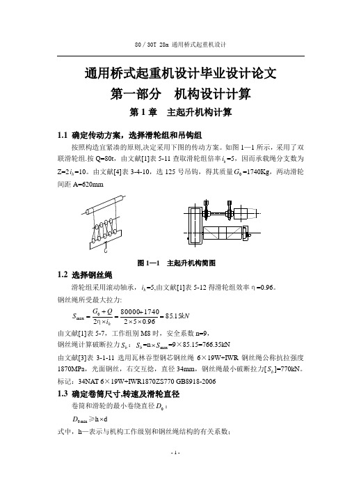
通用桥式起重机设计毕业设计论文第一部分 机构设计计算第1章 主起升机构计算1.1 确定传动方案,选择滑轮组和吊钩组按照构造宜紧凑的原则,决定采用下图的传动方案。
如图1—1所示,采用了双联滑轮组.按Q=80t ,由文献[1]表5-11查取滑轮组倍率h i =5,因而承载绳分支数为 Z=2h i =10。
由文献[4]表3-4-10,选125号吊钩,得其质量0G =1740Kg ,两动滑轮间距A=620mm图1—1 主起升机构简图1.2 选择钢丝绳滑轮组采用滚动轴承,h i =5,由文献[1]表5-12得滑轮组效率η=0.96。
钢丝绳所受最大拉力:kN i Q G S h 15.8596.05217408000020max =⨯⨯+=⨯+=η由文献[1]表5-7,工作组别M8时,安全系数n=9, 钢丝绳计算破断拉力b S :b S =n max S ⨯=9×85.15=766.35kN由文献[3]表3-1-11选用瓦林吞型钢芯钢丝绳6×19W+IWR 钢丝绳公称抗拉强度1870MPa ,光面钢丝,右交互捻,直径34mm ,钢丝绳最小破断拉力[b S ]=770kN 。
标记:34NAT 6×19W+IWR1870ZS770 GB8918-20061.3 确定卷筒尺寸,转速及滑轮直径卷筒和滑轮的最小卷绕直径0D : min 0D ≥h ⨯d式中,h —表示与机构工作级别和钢丝绳结构的有关系数;由文献[1]表5—10得:卷筒1h =25;滑轮2h =28;卷筒最小卷绕直径min j D =1h ⨯d=25⨯34=850mm ; 滑轮最小卷绕直径min h D =2h ⨯d=28⨯34=952mm 。
考虑起升机构布置卷筒总长度不宜太长,定滑轮直径取950mm,卷筒直径取D=1250㎜。
卷筒长度:15038)42128451018(2)4(23100+⨯++⨯⨯⨯⨯=+++⋅=ππL t Z D i H L h =2512mm ,取L=2500mm 。

桥式起重机桥式起重机是一种应用广泛的起重装置,它采用桥架结构横跨于工作场地,通过电动机或其他动力源提供动力,以实现货物的起重和搬运。
桥式起重机具有结构稳定、起重能力强、作用范围大等优点,被广泛应用于工厂、仓库、码头等各种场所。
桥式起重机一般由桥架、起重机构、电气设备等组成。
桥架是桥式起重机的主体部分,由两根跨越工作场地的大梁组成,梁上设置有焊接或螺栓连接的端梁,用于支承和固定整个起重机。
起重机构包括起升机构和行走机构,起升机构用于提升货物,行走机构用于在桥架上的移动。
电气设备则用来控制起重机的运行和各种功能。
桥式起重机的设计和制造需要考虑很多因素。
首先是载荷能力,根据不同工况的需要,选择适当的起重机型号和额定载荷能力。
其次是起重高度和行程,这决定了起重机在垂直方向上的工作能力。
同时,也需要考虑横向行走的距离和速度,以及各种安全措施,确保起重机的安全可靠运行。
桥式起重机的使用范围非常广泛。
在工厂中,桥式起重机可以用于装卸货物、组织生产流程、完成各种作业任务;在仓库中,桥式起重机可以实现货物的储存、堆放和提取;在码头上,桥式起重机可以实现集装箱的装卸和运输。
桥式起重机还被应用于建筑工地、电力站、冶金行业等各个领域。
桥式起重机的操作方法相对简单,但仍需要经过专业培训和持证上岗。
操作人员需要熟悉起重机的各个部件和控制系统,掌握正确的操作步骤和安全注意事项。
同时,也需要进行定期的检修和维护,确保起重机的正常运行和安全性能。
总的来说,桥式起重机是一种非常重要的起重设备,它具有结构稳定、起重能力强、使用范围广泛等优点。
它的出现和应用为人们的生产和生活提供了极大的便利,促进了工作效率的提高和经济的发展。
随着科技的不断进步,桥式起重机的性能和功能还会不断提升,为人们创造更多的价值。

附录外文文献原文:The Introduction of cranesA crane is defined as a mechanism for lifting and lowering loads with a hoisting mechanism Shapiro, 1991. Cranes are the most useful and versatile piece of equipment on a vast majority of construction projects. They vary widely in configuration, capacity, mode of operation, intensity of utilization and cost. On a large project, a contractor may have an assortment of cranes for different purposes. Small mobile hydraulic cranes may be used for unloading materials from trucks and for small concrete placement operations, while larger crawler and tower cranes may be used for the erection and removal of forms, the installation of steel reinforcement, the placement of concrete, and the erection of structural steel and precast concrete beams.On many construction sites a crane is needed to lift loads such as concrete skips, reinforcement, and formwork. As the lifting needs of the construction industry have increased and diversified, a large number of general and special purpose cranes have been designed and manufactured. These cranes fall into two categories, those employed in industry and those employed in construction. The most common types of cranes used in construction are mobile, tower, and derrick cranes.1.Mobile cranesA mobile crane is a crane capable of moving under its own power without being restricted to predetermined travel. Mobility is provided by mounting or integrating the crane with trucks or all terrain carriers or rough terrain carriers or by providing crawlers. Truck-mounted cranes have the advantage of being able to move under their own power to the construction site. Additionally, mobile cranes can move about the site, and are often able to do the work of several stationary units.Mobile cranes are used for loading, mounting, carrying large loads and for work performed in the presence of obstacles of various kinds such as power lines and similar technological installations. The essential difficulty is here the swinging of the payload which occurs during working motion and also after the work is completed. This applies particularly to the slewing motion of the crane chassis, for which relatively large angular accelerations and negative accelerations of the chassis are characteristic. Inertia forces together with the centrifugal force and the Carioles force cause the payload to swing as a spherical pendulum. Proper control of the slewing motion of the crane serving to transport a payload to the defined point with simultaneous minimization of the swings when the working motion is finished playsan important role in the model.Modern mobile cranes include the drive and the control systems. Control systems send the feedback signals from the mechanical structure to the drive systems. In general, they are closed chain mechanisms with flexible members [1].Rotation, load and boom hoisting are fundamental motions the mobile crane. During transfer of the load as well as at the end of the motion process, the motor drive forces, the structure inertia forces, the wind forces and the load inertia forces can result in substantial, undesired oscillations in crane. The structure inertia forces and the load inertia forces can be evaluated with numerical methods, such as the finite element method. However, the drive forces are difficult to describe. During start-up and breaking the output forces of the drive system significantly fluctuate. To reduce the speed variations during start-up and braking the controlled motor must produce torque other than constant [2,3], which in turn affects the performance of the crane.Modern mobile cranes that have been built till today have oft a maximal lifting capacity of 3000 tons and incorporate long booms. Crane structure and drive system must be safe, functionary and as light as possible. For economic and time reasons it is impossible to build prototypes for great cranes. Therefore, it is desirable to determinate the crane dynamic responses with the theoretical calculation.Several published articles on the dynamic responses of mobile crane are available in the open literature. In the mid-seventies Peeken et al. [4] have studied the dynamic forces of a mobile crane during rotation of the boom, using very few degrees of freedom for the dynamic equations and very simply spring-mass system for the crane structure. Later Maczynski et al. [5] studied the load swing of a mobile crane with a four mass-model for the crane structure. Posiadala et al. [6] have researched the lifted load motion with consideration for the change of rotating, booming and load hoisting. However, only the kinematics were studied. Later the influence of the flexibility of the support system on the load motion was investigated by the same author [7]. Recently, Kilicaslan et al. [1] have studied the characteristics of a mobile crane using a flexible multibody dynamics approach. Towarek [16] has concentrated the influence of flexible soil foundation on the dynamic stability of the boom crane. The drive forces, however, in all of those studies were presented by using so called the metho d of ……kinematics forcing‟‟ [6] with assumed velocities or accelerations. In practice this assumption could not comply with the motion during start-up and braking.A detailed and accurate model of a mobile crane can be achieved with the finite element method. Using non-linear finite element theory Gunthner and Kleeberger [9] studied the dynamic responses of lattice mobile cranes. About 2754 beam elements and 80 truss elements were used for modeling of the lattice-boom structure. On thisbasis a efficient software for mobile crane calculation––NODYA has been developed. However, the influences of the drive systems must be determined by measuring on hoisting of the load [10], or rotating of the crane [11]. This is neither efficient nor convenient for computer simulation of arbitrary crane motions.Studies on the problem of control for the dynamic response of rotary crane are also available. Sato et al. [14], derived a control law so that the transfer a load to a desired position will take place that at the end of the transfer of the swing of the load decays as soon as possible. Gustafsson [15] described a feedback control system for a rotary crane to move a cargo without oscillations and correctly align the cargo at the final position. However, only rigid bodies and elastic joint between the boom and the jib in those studies were considered. The dynamic response of the crane, for this reason, will be global.To improve this situation, a new method for dynamic calculation of mobile cranes will be presented in this paper. In this method, the flexible multibody model of the steel structure will be coupled with the model of the drive systems. In that way the elastic deformation, the rigid body motion of the structure and the dynamic behavior of the drive system can be determined with one integrated model. In this paper this method will be called ……complete dynamic calculation for driven“mechanism”.On the basis of flexible multibody theory and the Lagrangian equations, the system equations for complete dynamic calculation will be established. The drive- and control system will be described as differential equations. The complete system leads to a non-linear system of differential equations. The calculation method has been realized for a hydraulic mobile crane. In addition to the structural elements, the mathematical modeling of hydraulic drive- and control systems is decried. The simulations of crane rotations for arbitrary working conditions will be carried out. As result, a more exact representation of dynamic behavior not only for the crane structure, but also for the drive system will be achieved. Based on the results of these simulations the influences of the accelerations, velocities during start-up and braking of crane motions will be discussed.2.Tower cranesThe tower crane is a crane with a fixed vertical mast that is topped by a rotating boom and equipped with a winch for hoisting and lowering loads (Dickie, 990). Tower cranes are designed for situations which require operation in congested areas. Congestion may arise from the nature of the site or from the nature of the construction project. There is no limitation to the height of a high-rise building that can be constructed with a tower crane. The very high line speeds, up to 304.8 mrmin, available with some models yield good production rates at any height. They provide a considerable horizontal working radius, yet require a small work space on the ground(Chalabi, 1989). Some machines can also operate in winds of up to 72.4 km/h, which is far above mobile crane wind limits.The tower cranes are more economical only for longer term construction operations and higher lifting frequencies. This is because of the fairly extensive planning needed for installation, together with the transportation, erection and dismantling costs.3. Derrick cranesA derrick is a device for raising, lowering, and/or moving loads laterally. The simplest form of the derrick is called a Chicago boom and is usually installed by being mounted to building columns or frames during or after construction (Shapiro and Shapiro, 1991).This derrick arrangement. (i.e., Chicago boom) becomes a guy derrick when it is mounted to a mast and a stiff leg derrick when it is fixed to a frame.The selection of cranes is a central element of the life cycle of the project. Cranes must be selected to satisfy the requirements of the job. An appropriately selected crane contributes to the efficiency, timeliness, and profitability of the project. If the correct crane selection and configuration is not made, cost and safety implications might be created (Hanna, 1994). Decision to select a particular crane depends on many input parameters such as site conditions, cost, safety, and their variability. Many of these parameters are qualitative, and subjective judgments implicit in these terms cannot be directly incorporated into the classical decision making process. One way of selecting crane is achieved using fuzzy logic approach.Cranes are not merely the largest, the most conspicuous, and the most representative equipment of construction sites but also, at various stages of the project, a real “bottleneck” that slows the pace of the construction process. Although the crane can be found standing idle in many instances, yet once it is involved in a particular task ,it becomes an indispensable link in the activity chain, forcing at least two crews(in the loading and the unloading zones) to wait for the service. As analyzed in previous publications [6-8] it is feasible to automate (or, rather, semi-automate) crane navigation in order to achieve higher productivity, better economy, and safe operation. It is necessary to focus on the technical aspects of the conversion of existing crane into large semi-automatic manipulators. By mainly external devices mounted on the crane, it becomes capable of learning, memorizing, and autonomously navigation to reprogrammed targets or through prêt aught paths.The following sections describe various facets of crane automation:First, the necessary components and their technical characteristics are reviewed, along with some selection criteria. These are followed by installation and integration of the new components into an existing crane. Next, the Man –Machine –Interface (MMI) is presented with the different modes of operation it provides. Finally, thehighlights of a set of controlled tests are reported followed by conclusions and recommendations.Manual versus automatic operation: The three major degrees of freedom of common tower cranes are illustrated in the picture. In some cases , the crane is mounted on tracks , which provide a fourth degree of freedom , while in other cases the tower is “telescope” or extendable , and /or the “jib” can be raised to a diagonal position. Since these additional degrees of freedom are not used routinely during normal operation but rather are fixed in a certain position for long periods (days or weeks), they are not included in the routine automatic mode of operation, although their position must be “known” to the control system.外文文献中文翻译:起重机介绍起重机是用来举升机构、抬起或放下货物的器械。

桥式起重机专利技术综述桥式起重机是一种典型、重要的起重机械。
文章对桥式起重机主要结构和工作机构的专利文献进行了检索、统计、整理和分析,梳理了塔式起重机技术发展状况。
标签:起重机;技术;专利Abstract:The bridge crane is a typical and important lifting machinery. In this paper,the patent documents of the main structure and working mechanism of the bridge crane are searched,counted,sorted and analyzed,and the technical development situation of the tower crane is combed.Keywords:crane;technology;patent1 桥式起重机的概念桥式起重机是指以桥架为承载构件,由起升机构、小车运行机构和大车运行机构等几部分组成的起重机械。
桥式起重机是使用范围最广的起重机械,它在机械、冶金、交通、矿山的各类车间、仓库,在室内或露天固定跨间作安装、装卸及搬运起重工作,在工作机构方面,其具有起升机构,行走机构和控制系统,起升机构用于实现物品升降,行走机构用于实现桥式起重机位置的改变,控制系统用于实现起重机各个部件的功能。
2 技术发展状况对数据进行统计分析:(1)申请量年度统计分析。
从图1中可见,在除中国外的全球范围内,在1970年以前,其申请量处于较低水平,这一阶段的桥式起重机由最初的雏形发展为原型机并最终发展为结构功能比较完整的几代桥式起重机,这一阶段的申请量几乎集中在英国和美国,从这可以看出,自英国产业革命以后,桥式起重机被广泛地采用,但之后由于英国经常发生经济危机,工业生产停滞不前,桥式起重机的申请量在也骤减,美国也是世界上设计制造桥式起重机较早的国家之一,技术水平与生产能力较高。


摘要桥式起重机是一种提高劳动生产率重要物品搬运设备,主要适应车间物品搬运、设备的安装与检修等用途。
我国生产的吊钩电动双梁桥式起重机额定起重范围为5~500t,一般10t以上,起重机有主、副两套起升机构;300t以上,起重机还有三套起升机构。
电动双梁起重机由桥架、小车运行机构、大车运行机构和电气设备构成。
在系统整体设计中采用传统布局的典型结构,小车运行机构采用集中驱动。
起升机构滑轮组采用双联滑轮组,重物在升降过程中没有水平移动,起升过程平稳,且钢丝绳的安装和更换容易。
相应的卷绕装置采用单层卷筒,有与钢丝绳接触面积大,单位压力低的优点。
在起升机构中还涉及到钢丝绳、减速器、联轴器、电动机和制动器的选择等。
小车运行机构中涉及小车轮压计算、小车车轮、小车轨道、减速器、联轴器、电动机和制动器的选择计算等。
在起重机控制方面,起升机构用主令控制器和磁力控制屏来实现控制,大、小车运行机构用凸轮控制器直接控制。
在控制系统设计中,主要针对起升机构、大车运行机构、小车运行机构电路控制系统的设计及保护电路的设计。
利用低压电气元件控制起重机,其使用寿命较长,适合车间恶劣环境。
关键词:桥式起重机起升机构小车运行机构电气控制系统ABSTRACTBridge crane is a significant increase labor productivity goods handling equipment, primarily to carry goods workshops, equipment installation and maintenance, and other purposes. China's production of electrical hook rated double-beam bridge crane lifting the range of 5 ~ 500 t, generally more than 10 t, cranes are the main, two sets of lifting300 t above, there are three sets of cranes lifting bodies.Two-electric beam from the bridge crane, the trolley running, traveling mechanism and electrical equipment constituted. The overall design of the system using the traditional layout of the typical structure and operation of institutions used car driven focus. Pulley group or agency from using double-pulley blocks, heavy objects in the process of lifting the level of no movement, or from the process smooth, and the installation and replacement of wire rope easily. Winding installations in the corresponding single reel, a large area of contact with the rope, the advantages of low pressure units. In lifting bodies also involves rope, reducer, couplings, electrical and brake the choice. Vehicles involved in the operation of institutions pressure on the wheels, car wheels, car track, reducer, couplings, electrical and brake the choice of calculation.In the crane control, or from the institutions with the main controller and magnetic control of the screen to achieve control, big and small car cam controller running institutions with direct control. In the control system design, mainly for lifting bodies, traveling mechanism, the car run institutions circuit design and control system for the protection of the circuit design. Use of low-voltage electrical components control crane, a longer service life for workshop harsh environment.Key words: bridge crane hoisting mechanism car agencies operating electric control system目录中文摘要 (Ⅰ)英文摘要 (Ⅱ)1绪论 (1)1.1桥式起重机简介 (1)1.2普通桥式起重机的主要组成部分 (1)1.2.2大车 (1)1.2.2小车 (1)1.2.3动力装置和控制系统 (1)1.3普通桥式起重机的运行方式 (1)2设计任务及参数 (2)2.1主要技术参数 (2)2.2起重机工作机构的级别 (2)3吊钩组的设计计算 (3)3.1原始参数 (3)3.2设计步骤 (3)4滑轮组的设计计算 (8)5钢丝绳的选择 (11)6卷筒的设计计算 (12)7钢丝绳在卷筒上的固定 (16)8起升机构的设计计算 (18)8.1原始参数 (18)8.2设计计算步骤 (18)9小车运行机构的设计计算 (26)9.1原始参数 (26)9.2设计计算步骤 (26)10起重机主梁的设计计算 (36)10.1桥式起重机主梁的设计计算主要涉及内容 (36)11安全装置的选择说明 (37)11.1主要安全装置的说明 (37)11.1.1走台与栏杆 (37)11.1.2排障板 (37)11.1.3小车行程限位开关 (37)11.1.4起升高度限位开关 (37)11.1.5大车行程限位开关 (37)11.1.6缓冲器与挡铁 (37)11.2小车缓冲器选择计算 (38)11.3大车缓冲器选择计算 (39)12 20吨桥式起重机的控制系统设计 (40)12.1控制电路设计分析 (40)12.1.1控制对象分析及控制元件的确定 (40)12.1.2控制系统的基本要求 (40)12.1.3电动机的工作状态分析 (41)12.1.4起重机的供电 (43)12.2起升机构控制电路的工作原理 (44)12.2.1起升机构控制电路的特点 (44)12.2.2起升机构电路的保护与联锁 (44)12.2.3起升机构电气工作控制原理 (45)12.3小车运行机构电路工作原理 (49)12.3.1小车运行机构电路工作特点 (49)12.3.2小车运行机构的电气控制原理 (50)12.4大车运行机构电路工作原理 (51)12.4.1大车运行机构电路工作特点 (51)12.4.2大车运行机构的电气控制原理 (52)12.5保护电路的工作原理 (53)12.5.1保护电路的组成 (53)结束语 (55)参考文献 (56)附录1触点状态表1.1起升机构主令控制器SA触点状态表1.2小车凸轮控制器SA1触点状态表1.3大车凸轮控制器SA2触点状态表附录2电气原理图2.1起升机构电气原理图2.2小车运行机构电气原理图2.3大车运行机构电气原理图2.4保护电路电气原理图2.5 20t桥式起重机总电气原理图1 绪论1.1桥式起重机的简介桥式起重机是生产车间、料场、电站厂房和仓库中为实现生产过程机械化和自动化,减轻体力劳动,提高劳动生产率的重要物品搬运设备。

国家标准英文版助力中国起重机械走出去
佚名
【期刊名称】《起重运输机械》
【年(卷),期】2017(0)9
【摘要】近年来,全国起重机械标准化技术委员会组织起重机械行业开展了对GB /T3811—2008《起重机设计规范》、GB5144-2006《塔式起重机安全规程》、GB6067.1-2010《起重机械安全规程第l部分:总则》、GB/T14405—2011《通用桥式起重机》、GB/T14406-2011《通用门式起重机》、
【总页数】1页(P30-30)
【关键词】起重机械;国家标准;标准化技术委员会;中国;英文;安全规程;塔式起重机;桥式起重机
【正文语种】中文
【中图分类】TH21
【相关文献】
1.中国绿色画报联手召开《中国文化走出去对外传播》论坛——暨《谁是当今最科学的民主》英文版出版座谈会 [J], ;
2.《中国造船质量标准》《中国修船质量标准》两项国家标准(中英文版)解读 [J], 李东
3.《中国造船质量标准》《中国修船质量标准》两项国家标准中英文版发布会在京召开 [J], ;
4.“中国学术期刊‘走出去’国际化增强传播工程”助力中国学术期刊“走出去”
[J], 肖宏; 孙红梅; 齐琪
5.两项造纸国家标准英文版审查通过,将有利于国内造纸企业产品“走出去” [J],因版权原因,仅展示原文概要,查看原文内容请购买。
Frequency Variation Speed Control1 The Popularity and Prospect of Frequency Variation Speed ControlThe electrical machinery exchange frequency conversion velocity modulation technology is the electricity saving, the improvement technical process improves the product quality and the improvement environment, the impetus technology advancement one main method now The frequency conversion velocity modulation by its outstanding velocity modulation and the braking quality, the high efficiency, the high power factor and the electricity saving effect, the widespread applicable scope and other many merits by the domestic grandfather was thought most has the development future velocity modulation way.The electrical transmission control system usually by the electric motor, the control device and the information installs 3 parts to be composed, the electrical transmission relates uses the electric motor by to save the electrical energy and to control the machinery reasonably the operating condition, the realization electrical energy - mechanical energy transformation, achieves, the high production, the low consumption goal high quality.The electrical transmission divides into does not modulate velocity and modulates velocity two big kinds, the velocity modulation is divided the exchange to modulate velocity and to direct current modulates velocity two ways.The variable speed motor directly does not supply power by the electrical network But the machinery which does not modulate velocity along with electric power electronic technology development this kind of original manuscript more and more many changes to the velocity modulation transmission by to save the electrical energy The improvement product quality, enhances the output Therefore the velocity modulation transmission is an important profession, already obtained the country to take, at present had certain scale.In recent years exchanged in the velocity modulation most to be active, to develop quickest is the frequency conversion velocity modulation technology, the frequency conversion velocity modulation is exchanges the velocity modulation foundation and the branch content. The last century transformer appearance causes the change voltage to become very much easy, thus has accomplished a huge electric power profession. Since long ago, the alternating current frequency always is fixed, the frequency conversion velocity modulation technology appearance causes the frequency to become may the full use resources.In this recent 10 years, the frequency conversion technology application has the very big development in our country, and obtained the good effect to be possible to say, the frequency conversion technology has accepted for the majority users, but had no alternative but to point out, our country in frequency conversion technology application aspect, with developed country level Shang You very big disparity. At present, the AC motors we are using now use frequency variation speed control only about 6%, but the developed country is 60%~70%, Japan on air blower, water pump frequency conversion velocity modulation use rate is 10%, but our country is less than 0.01%, In Japan air-conditioner using frequency variation technique rate is 70%, but our country's only then just started Embarks from this reality, frequency conversion technology remain have the very big development space, we should complete the promoted application work doggedly.And with the constant development of control technique and control avenue, frequency variation speed controlled has developed the vector controlled frequency variation velocity modulation, by controlling the AC motor inside act for shunt DC motor field coper’s flux, to enhance the permanent torque output scope and static and dynamic character, make the AC motor frequency variation speed controlled system superior to DC motor voltage variation speed controlled system. For simplifying the control system, reducing the fault rate, there has developed a vector controlled frequency variation speed control without speed sensor which based on the vector controlled frequency variation speed control. In some application which have low require , vector controlled frequency variation speed control without speed sensor could completely compare with the vector controlled frequency variation speed control that have speed sensor. The vector control has the epoch-making significance to the AC current motor velocity modulation.Frequency variation speed control is the best way in the motor speed modulation, it is the perfect gear in the company’s technical reform and product renewal, it is the essential composition in the industrial automatic system, it is the assumption of realizing the automatic of product proceed and management, it is also the precondition in the development of informationization In our country’s traditional estate, using the DC motor speed control actuation account about 85%~90% in the speed controlled system, but the AC speed controlled system account about 10%~15%. Low efficiency, bad quality, large cost, high fault rate have alreadybeen the bottleneck that restrain the development of the company. So, we must promote the advanced AC frequency variation speed control technique positively, arms the traditional industry with the advanced equipment, promote a further development in the automation, the industrialization and the informationization.2 Our Country’s Development Condition in Speed Controlled TechniqueOur country is a developing country, so many product’s research ability has behind the developed countries. From now on, the product of frequency variation speed controlled that ourselves made only act for last century 90s in the international. With the reform and opening, rapid development of economic, forms a large market, it opens to the country companies, also the foreign companies. Many products are exported from the developed countries, and runs well in our country, satisfied our need in fabrication and living. Many copartership companies in our country make the international advanced products.The domestic complete department independently is designing the manufacture in the complete set installment to use the foreign import company and the joint venture supposes advanced each, own develop the application software, can provide the first-class electrical transmission control system for the domestic and foreign important engineering project. Although obtains very many result, but should see because domestic develops, the production product ability voluntarily is weak, is serious to the overseas company's dependence.As early as in the country "85" technical attack plan, the alternating velocity modulation technique was listed as the key technical attack project, b ut because our country’s electric power and electronic device aggregate level is very low, although the production of IGBT、GTO component has introduced the overseas technique, it has not formed the economies of scale benefit, almost does not have the independent development ability of new frequency converter production, this has affected the domestic frequency conversion velocity modulation technique development in the certain degree. In the high efficiency AC-AC frequency convert technique、the motors without commutator technique and so on, the domestic product also has the suitable disparity in the digitization and the system reliable aspect compares with the overseas level, in the medium efficiency frequency convert technique, nearly all productions use ordinary V/F control inland, few adopt the vector control technique, and can not satisfied the marketrequirement in the variety and quality.But in overseas, the frequency conversion technique obtains the full development, and has obtained the remarkable achievement in each aspect. In power component aspect, high voltage、the appearance of SCR、GTO、IGBT、IGCT with high current capacity and the using in series and parallel, the high-pressured and high efficiency frequency converter production obtains the production and the promoted application. In microelectronic technique aspect, 16bit and 32bit high speed microprocessors as well as the fast development of DSP and ASIC technique, provided the hardware method in realizing the frequency converter which with high accuracy multi-purpose.In theory aspect,the vector control, the magnetic flux control, the torque control, the intelligent control, the new control theory and so on have provided the related rationale for the high performance frequency converter development, we may see that, in the overall, the alternating frequency conversion velocity modulation technique in our country has big disparity compares with international level.Therefore, the AC frequency variation speed control technique has the following sides:1) The basic research of control strategy in frequency converter has a large gap compares with the foreign level.2) The technical level of the whole machine is low in the frequency converter, although we had input certainly people, material resources, but because of the disperse power, did not form a certainly technique and production scale.3) All the semiconductor power device product in the frequency converter is blank.4)Correlative Industries and relative Industries drop behind.5) Few production and sale, low reliable and technological standards.With the development and improvement in the power electronic technique, power divert based on power electronic circuit technique and various control technique, the AC frequency variation speed controlled technique is mature day by day, and sure to be the main way in the future. With the constant development of power electronic technique, reliable character, well adoption, cheap price that the frequency converter have will become true. This technique will gain widely, popularity application .At present, foreign developed countries’ frequency convert technique towards to the miniaturization, high reliability, defend with harm, more function, high character, and our country is coming on now.外刊资料翻译:变频技术1 变频技术的普及前景电机交流变频调速技术是当今节电、改善工艺流程以提高产品质量和改善环境、推动技术进步的一种主要手段。