8100智能水泵变频器说明书(130-190)-2015-09-08
- 格式:pdf
- 大小:3.38 MB
- 文档页数:60

U L arge, Easy-to-Read LED, Selectable for EitherSetpoint or ProcessTemperatureU T ype J or KThermocouple InputU A djustable O utputHysteresis to PreventRapid Cycling AroundSetpoint TemperatureU A djustable Deviation Alarm Flashes When MeasuredTemperature Exceedsor Falls Below SetpointTemperatureU N EMA 4X (IP65) FrontBezel, Splash-Proof andResistant to DustU D iscrete Status Indicators Illuminate WhenTemperature Display,Setpoint Display or Heat/Cool Output Is ActiveU A uto Tuning (CN8101and CN8102)CN8100 SeriesThe CN8100 Series controller is alow-cost, general purpose 1⁄4 DINtemperature controller, ideal for OEM or replacement applications. Microprocessor-based and accurate to ±0.3% FS, it may be orderedas either a PID controller, on/off controller or limit safety device.As a separate safety feature to your control application, the CN8121-R1 limit controller provides reliable high/ low temperature limit shut-off control for most machine and process control applications including environmental chambers, furnaces, SpecificationsGeneralLine Voltage: 85 to 250 Vac, 50/60 Hz,120 to 300 Vdc (auto polarity)Display: 3-digit, 14 mm (0.56")orange LEDDiscrete Indicators:Setpoint: AmberActual: AmberHeat: OrangeCool: OrangeCN8102-R1-R2, dual output PIDcontroller shown smaller thanactual size.Power Consumption:Less than 6 VA (instrument)Front Panel Rating: NEMA 4X (IP65)Operating Temperature:0 to 60°C (32 to 140°F)Humidity Tolerance: 90% RHmaximum, non-condensingMemory Protection:Solid-state, non-volatile memoryConnections: Fast-on style(0.250" wide)Panel Cutout:1⁄4 DIN, 92 mm2 (3.622 in2)Dimensions: 96 x 96 x 6.35 mm bezel(3.78 x 3.78 x 0.25")Panel Depth: 88.9 mm (3.5")Weight: 737 g (1 lb. 10 oz)PerformanceAccuracy: ±0.3% of FS, ±1 digitSetpoint Resolution: 1 countRepeatability: ±1.0 countTemperature Stability:5µV/°C maximumovens and packaging machinery. Asa high-limit device, these controllershave a normally energized SPSTlatching output relay which becomesde-energized whenever the processvariable (PV) exceeds a selectedsetpoint value. Reset of the latchingoutput relay is done by holding theparameter button for 3 seconds onthe front panel of the controller, orby cycling power to the controller.1⁄4 DIN Digital Temperature and Limit ControllersP a n e l p u n c h es a v a i l a b l e* Specify output type from Output Options table.Ordering Examples: CN8102-R1-R2, 1⁄4 DIN dual mechanical relay output PID controller.OCW-3, OMEGACARE SM extends standard 2-year warranty to a total of 5 years.CN8121-R1.Controllers shownsmaller than actual size.CN8102-R1-R2.CN8111-R1.TC Cold End Tracking: ±0.05°C/ °C ambientNoise Rejection: Common mode >100 dB, Series mode >70 dBProcess Sampling: 3.7 Hz (270 ms)Available Inputs: Thermocouple: CN8110: Type J CN8120: Type J CN8100: Type J or K Maximum lead resistance, 100 Ω for rated accuracy Control Characteristics:Control Hysteresis: 1 to 140°C (2 to 252°F)Display Offset: -70 to 70°C (-126 to 126°F)Deviation Alarm: Off, 1 to 140°C (Off, 1 to 252°F)Outputs: Electromechanical relay, 5 A @ 250 Vac, 5 A @ 30 Vdc, solid-state relay, 120/240 Vac, 0 voltage switched, 2 A continuous (output 1), 0.5 A continuous (output 2) 10 A surge @ 25°C (77°F), pulsed DC 5V for external SSROMEGACARE SMextended warranty program is available for models shown on this page. Ask your sales representative for full details when placing an order. OMEGACARE SMcovers parts, labor and equivalent loaners.。


用户手册前言感谢您选用8100智能水泵变频器,本说明书为您提供相关的操作说明及参数的详细解释,安装、运行、维护或检查之前,敬请认真阅读本说明书。
使用前,务必确认接线是否正确以及水泵的转向是否正确。
目录第一章操作面板说明 (06)1.1操作面板示意图 (06)1.2指示灯说明 (06)1.3按键操作说明 (07)1.4压力设置说明 (08)第二章型号、外观及接线 (09)2.1型号说明 (09)2.2外形尺寸和安装尺寸 (09)2.3主电路与控制端子接线图 (15)2.4传感器接线图 (16)2.5端子标识及说明 (17)第三章快速调试 (19)第四章8100参数表 (22)4.1运行状态面板显示参数 (22)4.2停机状态面板显示参数 (22)4.3单机常用参数组 (23)4.4多泵联机常用参数组 (25)4.5调试参数组 (26)4.6PID及休眠参数组 (27)4.7水泵保护参数组 (29)4.8电机参数组 (30)4.9保护和故障参数组 (31)4.10端子参数组 (33)4.11通讯参数组 (34)4.12监控参数组 (35)4.13代理商参数组 (36)4.14厂家参数组 (36)4.15部分参数详细说明 (37)第五章故障信息及排除方法 (45)5.1故障代码详述 (45)5.2常见故障及其处理方法 (48)第六章通讯协议 (50)6.1命令码及通讯数据描述 (50)第七章典型应用案例 (54)7.1单泵控制案例1 (54)7.2单泵控制案例2 (55)7.3多泵控制案例 (57)7.4多联机通讯协议 (57)7.5一拖二控制案例 (58)安全注意事项危险:表示可能会导致死亡或严重人身伤害的状况。
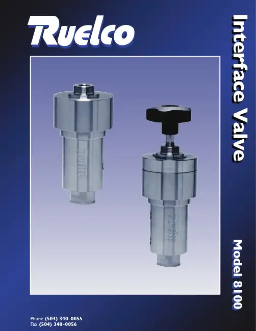
Phone (504) 340-0055Fax (504) 340-0056Interface ValveModel 8100Model 8100While this information is presented in good faith and believed to be accurate, Ruelco, Inc. does not guarantee satisfactory results from reliance upon such information. Nothing contained herein is to be construed as a warranty or guarantee, expressed or implied, regarding the performance, merchantability, and fitness with respect to the products. Ruelco, Inc. reserves the right, without notice, to alter or improve the designs or specifications of the products described herein.Model 8100FEATURES316 Stainless steel construction (models to N.A.C.E. MR0175 available).Large Cv factor assures fast system response All soft seal designDesign minimizes malfunctions due to supply system debris.GENERAL DESCRIPTION:The Ruelco Interface Valve is a normally closed 3-way block and bleed Hydraulic Controller.The valve allows the system to control pressures as high as 10,000psi.with a pilot supply pressure of 100psi. The unique soft seal design ensures zero leakage and also prevents damage from foreign particles. Ruggedly constructed for years of reliable service.Parts List For Interface ValveDimensionsSwitch Specifications8100-10000Ordering Code:Interface ValveITEM QTY.DESCRIPTIONMATERIALPART NO.12Cap Piston Seal Spool Assembly Piston SpringSpool Back-Up SealSpool Seal Shaft SealBodySleeve Sleeve Back-Up SealSleeve Seal Bottom Sleeve Center SealBottom Cap Seal Bottom CapRepair Kit for 8100-10000Stainless SteelViton Stainless Steel Stainless Steel Teflon Buna Fluoromyte Stainless SteelStainless SteelTeflon Buna Stainless Steel DelrinBuna Stainless Steel *Items3*567*8*9*10*11*1213*14*151617*181911111111221111111181-001-000V0-145-75H 81-009-00081-014-000TF-008-75H V0-008-90H FM-250-25081-003-00081-006-000TF-016-75H N0-016-75H 81-005-00081-011-000N0-017-75H 81-004-00081-016-000Panel Mount NutStainless Steel 4110-006-000BallTungsten Carbide BL-375-10M Seal Spring Stainless Steel81-015-000Valve TypeMax.Supply Pressure Outlet Orifice Size Ambient TemperatureRange Sensor Type Max.Oper.Pressure Burst Pressure3-Way 200PSI..125IN.-20°TO 250°F -20°TO 122°C Piston10,000PSI (680BAR)20,000PSI.(1380BAR)Panel Mount Hole Valve Ports Weight1.0IN (25.4mm)1/4"FNPT 4.9LBS (2.30KG)A B3.125IN (79.4mm)5.75IN (146.1mm)While this information is presented in good faith and believed to be accurate, Ruelco, Inc. does not guarantee satisfactory results from reliance upon such information. Nothing contained herein is to be construed as a warranty or guarantee, expressed or implied, regarding the performance, merchantability, and fitness with respect to the products. Ruelco, Inc. reserves the right, without notice, to alter or improve the designs or specifications of the products described herein.Model 8100FEATURES316 Stainless steel construction (models to N.A.C.E. MR0175 available).Large Cv factor assures fast system response All soft seal designDesign minimizes malfunctions due to supply system debris.GENERAL DESCRIPTION:The Ruelco Interface Valve is a normally closed 3-way block and bleed Hydraulic Controller.The valve allows the system to control pressures as high as 10,000psi.with a pilot supply pressure of 100psi.The unique soft seal design ensures zero leakage and also prevents damage from foreign particles.Ruggedly constructed for years of reliable service.The manual override option can be used to manually operate the valve even while at maximum control pressure.8100-20000Ordering Code:Interface Valve with overrideParts List For Interface Valve 8100-20000DimensionsSwitch SpecificationsItem Qty.DescriptionMaterial Part No.12Set Screw Piston Seal Spool Assembly Piston SpringSpool Back-Up SealSpool Seal Shaft SealBodySleeve Sleeve Back-Up SealSleeve Seal Bottom Sleeve Center SealBottom Cap Seal Bottom CapRepair Kit for 8100-20000Stainless Steel Viton Stainless Steel Stainless Steel Teflon Buna Fluoromyte Stainless SteelStainless SteelTeflon Buna Stainless Steel DelrinBuna Stainless Steel *Items10*121314*15*16*17*18*1920*21*222324*2526111111112211111111T1-08K-0C3V0-145-75H 81-009-00081-014-000TF-008-75H V0-008-90H FM-250-25081-003-00081-006-000TF-016-75H N0-016-75H 81-005-00081-011-000N0-017-75H 81-004-00081-017-000Handle Technopolymer 11181-012-000BallTungsten Carbide BL-375-10M Seal Spring Stainless Steel81-015-000Override Stem Panel Mount Nut Override Cap Air Ring O-Ring Override Seal Air Ring Snap Ring Stainless Steel Stainless Steel Stainless Steel Viton Viton Stainless SteelStainless Steel3567*8*911121181-010-00010-006-00081-002-000V0-125-75H V0-013-75H 81-013-000SH-150-05041Valve TypeMax.Supply Pressure Outlet Orifice Size Ambient TemperatureRange Sensor Type Max.Oper.Pressure Burst Pressure3-Way 200PSI..125IN.-20°TO 250°F -20°TO 122°C Piston10,000PSI (680BAR)20,000PSI.(1380BAR)Panel Mount Hole Valve Ports Weight1.0IN (25.4mm)1/4"FNPT 5.2LBS (2.44KG)A B (MAX.) 3.125IN (79.4mm)8.75IN (222.3mm)Hydraulic ControllersSS-H Hydraulic Pilot VC-2 Velocity Check Valve RQ-1 (1/4") Quick Exhaust RQ-2 (1/2") Quick ExhaustInterface Valve RD-1 Dump Valve RD-H Dump Valve Hydraulic Tattletale Indicator。


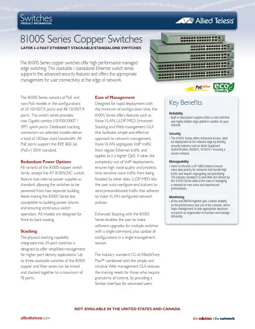
The 8100S Series copper switches offer high performance managed edge switching. This stackable / standalone Ethernet switch series supports the advanced security features and offers the appropriate management for user connectivity at the edge of network.Reliability»Built-in dual power supplies offers a cost-effective and highly reliable edge platform solution for your network.Security»The 8100S Series offers enhanced access, ideal for deployment at the network edge by offering security features such as Multi Supplicant Authentication, RADIUS, TACACS+ ensuring a secure network.Manageability»Voice VLAN and LLDP-MED features ensure voice data priority for networks that handle high traffic and require segregating and prioritizing. The industry standard CLI and Web GUI offered by the 8100S Series adds to the ease of managing a network for new users and experienced professionals.Monitoring»sFlow and RMON together give a better visibility on the performance and use of the network, which helps management to take appropriate decisions crucial for an organization to function and manage efficiently.The 8100S Series consists of PoE and non-PoE models in the configurations of 24 10/100TX ports and 48 10/100TX ports. This switch series provides two Gigabit combo (10/100/1000T /SFP) uplink ports. Dedicated stacking connectors on selected models deliver a total of 10Gbps stack bandwidth. All PoE ports support the IEEE 802.3at (PoE+) 30W standard.Redundant Power OptionsAll variants of the 8100S copper switch family, except the AT-8100S/24C switch, feature two internal power supplies as standard, allowing the switches to be powered from two separate building feeds making the 8100S Series less susceptible to building power failures and ensuring continuous switchoperation. All models are designed for front-to-back cooling.StackingThe physical stacking capability integrated into 24-port switches isdesigned to offer simplified management for higher port density applications. Up to three stackable switches of the 8100S copper and fiber series can be mixed and stacked together to a maximum of 78 ports.Key BenefitsEase of ManagementDesigned for rapid deployment with the minimum of configuration time, the 8100S Series offers features such as Voice VLAN, LLDP-MED, Enhanced Stacking and Web management GUI that facilitates simple and effective approach to network management.Voice VLAN segregates VoIP traffic from regular Ethernet traffic and applies to it a higher QoS. It takes the complexity out of VoIP deployments, ensures high voice quality and protects time sensitive voice traffic from being flooded by other data. LLDP-MED lets the user auto-configure end stations to send preconditioned traffic that adheres to Voice VLAN configured network policies.Enhanced Stacking with the 8100S Series enables the user to makesoftware upgrades for multiple switches with a single command, plus update all configurations in a single management session.The industry standard CLI of AlliedWare Plus™ combined with the simple and intuitive Web management GUI reduces the training needs for those who require granularity of control, by providing a familiar interface for advanced users.8100S Series Copper SwitchesLAYER 2-4 FAST ETHERNET STACKABLE/STANDALONE SWITCHESSwitchesproduct informationSimplifying the Network AutoQoS with the 8100S Series enables a switch administrator to enter one command to enable all the appropriate features for the recommended QoS settings on edge and uplink port so this minimizes the complexity and speeding up the QoS deployment over the network.Environmentally FriendlyIn keeping with our commitment to environmentally friendly processes and products, the 8100 Series is designed to be green from the ground up, with reduced power consumption and minimal hazardous waste.The use of highly recyclable metal, combination of green production processes, earth friendly packaging, high efficiency power supplies and effective power management deliver both cost savings and a reduced carbon footprint for the user.Access Control ListsAccess Control Lists work as filters that can enable inspection and classification of incoming frames. Specific actions can then be performed on these defined frames to more effectively manage the network traffic at Layer 2 through Layer 4. ACLs are typically used as security mechanism, either permittingor denying entry for packets on specific switch ports.Layer 3 RoutingThe switch provides static IPv4 routing at the edge of the network as well as support for RIPv1 and RIPv2.Effective Traffic MonitoringIn order to fully understand theperformance of the network and ensurethe ongoing smooth delivery of criticaldata, users must be able to measureand analyze the traffic in real time.The 8100S Series facilitates effectivetraffic monitoring with sFlow, anindustry-standard technology formonitoring high-speed switchednetworks gives complete visibilityinto the use of the network enablingperformance optimization, accounting,billing for usage, and even defenseagainst security threats.Securing the Network EdgeThe 8100S Series guaranteesprotection and secure management ofadministrator’s network by providingstrong security standards andauthentication mechanism for access atthe edge of a network.IEEE 802.1x port authenticationmethods such as PEAP, EAP-TLS andEAP-TTLS supported by the 8100SSeries allows network controller torestrict external devices from gainingunauthenticated access in to thenetwork.The Multiple Supplicant Authenticationenables the switch to uniquelyauthenticate and apply the appropriatepolicies and VLAN for multiple users ordevices on a shared port, allowing portexpansion while keeping the networksecure.Power over EthernetThe 8100S Series comes inconfigurations of 24- and 48-port PoE.Both support PoE+ (IEEE 802.3at),which delivers up to 30W per port.Power over Ethernet allows user tonetwork and power a device using singleEthernet cable, thus eliminating theneed for additional power outlets andsimplifying the network installation. It isalso unaffected by local variance in ACpower, offering a standardized powerinfrastructure.PoE+ with up to double the powerprovides superior power-managementcapability, as automatic power allocationcan be made based on the exactrequirement of the power device at agiven time.Gigabit and Fast Ethernet SFPSupportThe 8100S Series supports bothGigabit and Fast Ethernet Small Form-Factor Pluggable (SFP) uplinks. Thedual-speed ports make this series idealfor environments where Gigabit fiberswitches will be phased in over time.The 8100S Series allows for connectivityto the legacy 100FX hardware until theuplink device is upgraded to Gigabit.SpecificationsSystem Capacity»128MB RAM»16MB flash memory»16K MAC addresses»266MHz CPUMaximum Bandwidth»Non-blocking for all packet sizesWirespeed Switching (Layer 2/3) on all Ethernet Ports»14,880pps for 10Mbps Ethernet»148,800pps for 100Mbps Ethernet»1,488,000pps for 1000Mbps Ethernet Environmental Specifications»Operating temperature: 0ºC to 40ºC»Storage temperature: -25ºC to 70ºC»Operating humidity: 5% to 90% non-condensing»Storage humidity: 5% to 95% non-condensing»Max operating altitude: 3,048 m (10,000 ft)Port Configuration»Auto-negotiation, duplex, MDI/MDI-X, IEEE 802.3x flow control/back pressure»Head of Line (HoL) blocking prevention»Broadcast storm control»Link flap protection»Group link control»Port mirroringEthernet Specifications»RFC 894 Ethernet II encapsulation»IEEE 802.1D MAC bridges»IEEE 802.1Q Virtual LANs»IEEE 802.2 Logical link control»IEEE 802.3ac VLAN TAG»IEEE 802.1ax-2008 (LACP) link aggregation»IEEE 802.3u 100TX»IEEE 802.3x Full-duplex operation»IEEE 802.3z Gigabit Ethernet»IEEE 802.3af Power over Ethernet class 3»IEEE 802.3at Power over Ethernet class 4»Jumbo frames (9198 bytes)Quality of Service (QoS)»Eight egress queues per port»Egress rate limiting»Voice VLAN»Automatic QoS»IEEE 802.1p Class of Service with strict and weighted round robin scheduling»RFC 2474 DSCP for IP-based QoS»RFC 2475 Differentiated services architecture»Layer 2, 3 and 4 criteria Link Aggregation»IEEE 802.3ad LACP - eight groups»Static link aggregation - 24 groupsLink Discovery»IEEE 802.1ab Link Layer Discovery Protocol (LLDP)»Link Layer Discovery Protocol-Media Endpoint(LLDP-MED)Spanning-Tree Protocol»IEEE 802.1D Spanning-Tree Protocol»IEEE 802.1D-2004 Rapid Spanning-Tree Protocol»IEEE 802.1q-2005 Multiple Spanning-Tree Protocol(15 instances)»BPDU guard»Loop guard»Root guardVLAN»4096 VLANs (IEEE 802.1Q)»Port-based VLANs»MAC-based VLANs – 256»IP subnet-based VLANs – 256»Port-based Private VLANs»GARP VLAN Registration Protocol (GVRP)MIB Support»RFC 1213 MIB-II»RFC 1215 TRAP MIB»RFC 1493 Bridge MIB»RFC 2863 Interfaces group MIB»RFC 1643 Ethernet-like MIB»RFC 2618 RMON MIB»RFC 2674 IEEE 802.1Q MIB»RFC 2096 IP forwarding table MIB»Allied Telesis managed switch MIBManagement»RFC 854 Telnet server»Console management port»AlliedWare Plus CLI»Web GUI»Enhanced Stacking»RFC 1866 HTML»RFC 2068 HTTP»RFC 2616 HTTPS»RFC 1350 TFTP»zModem»RFC 1305 SNTP»RFC 1155 MIB»RFC 1157 SNMPv1»RFC 1901 SNMPv2c»RFC 3411 SNMPv3»RFC 1757 RMON 4 groups: Stats, History, Alarmsand Events»RFC 3164 Syslog protocol (client)»Event log»RFC 3176 sFlow»Auto configGeneral Protocols»RFC 768 UDP»RFC 791 IP»RFC 792 ICMP»RFC 793 TCP»RFC 826 ARP»RFC 950 Subnetting, ICMP»RFC 1027 Proxy ARP»RFC 1035 DNS»RFC 1122 Internet host requirements»DHCP client»DHCP snooping»DHCP option 82»RFC 3046 DHCP relay»RFC 951 BootPIP Multicast»RFC 1112 IGMPv1 snooping»RFC 2236 IGMPv2 snooping»IGMPv2 snooping querier»Multicast groups – 255IPv6»IPv6 host»IPv6 ACL»ICMPv6»Dual-stack IPv4/IPv6 management»IPv6 applications: WEB/SSL, Telnet server/SSHSecurity / IEEE 802.1x»TACACS+»RFC 2865 RADIUS client»RFC 2866 RADIUS accounting»IEEE 802.1x port-based Network Access Control(NAC)»Supplicant»Authenticator»IEEE 802.1x multiple supplicant mode»Piggy-back mode»Per port MAC address limiting»Per port MAC address filtering»MAC address security/lockdown»RFC 1321 MD-5»EAP, EAP-TLS, LEAP, PEAP, TTLS»Dynamic VLANs»Guest VLANs»Secure VLANs»Layer 2/3/4/ Access Control Lists (ACLs)»SSLv3 for Web management»SSL»SSH»SSH session time out»Microsoft NAP compliant»Symantec NAC supportPhysical Specifications and MTBF FiguresPower and Noise CharacteristicsPower over Ethernet Specifications * Standard product with dual AC power supply with maximum PoE+ load†Standard product with single AC power supply IEEE 803.at PoE+ LLDP-MED classification requires PD to be fully compliant with IEEE 802.3at standard Mode B PoE carries PoE power to powered devices on spare pairs 4/5 and 7/8 of Ethernet interfaceIP Routing»Static IPv4 routing – 4K »RIPv1, v2 »Proxy ARPStacking Features»10Gbps stacking bandwidth via dedicated HDMI stacking ports»Hardware stack up to three units (78 ports) using HDMI stacking ports or stack up to 24 units using Enhanced Stacking»Single system appearance »Single IP management »Backup master»Link aggregation / trunking across hardware stack »Port mirroring across stack »VLAN across stack»Maximum HDMI stacking cable length 1mCompliance Standards»IEEE 802.3 – 10T»IEEE 802.3u – 100TX with auto-negotiation »IEEE 802.3ab – 1000T Gigabit Ethernet »100FX SFP support »1000X SFP supportSafety and Electromagnetic Emissions Certifications»EMI: FCC class A, CISPR class A, EN55022 class A, C-TICK, VCCI Class A, CE, EN601000-3-2, EN601000-3-3 »Immunity: EN55024»Safety: UL 60950-1 (cUlus), EN60950-1 (TUV), EN60825RoHS Standards»Compliant with European and China RoHS standardsPackage Description»AT-8100S/xx switch »AC power cord(s)»Management cable (RJ-45 to DB-9)»Rubber feet for desktop installation and 19” rack-mountable hardware kit accessories»Install guide and CLI users guide available at »HDMI stacking cable (1 meter)North America Headquarters | 19800 North Creek Parkway | Suite 100 | Bothell | WA 98011 | USA | T: +1 800 424 4284 | F: +1 425 481 3895Asia-Pacific Headquarters | 11 Tai Seng Link | Singapore | 534182 | T: +65 6383 3832 | F: +65 6383 3830EMEA & CSA Operations | Incheonweg 7 | 1437 EK Rozenburg | The Netherlands | T: +31 20 7950020 | F: +31 20 79500218100S Copper Series | Layer 2–4 Fast Ethernet Stackable SwitchesOrdering Information8100S Series Copper SwitchesAT-8100S/24C-xx 24 10/100TX ports2 combo ports (10/100/1000T-100/1000 SFP) 2 HDMI stacking portsStandard one AC power supply in a compact form factor AT-8100S/24-xx 24 10/100TX ports2 combo ports (10/100/1000T-100/1000 SFP)) 2 HDMI stacking portsStandard two AC power supplies or optional DC power supplies*AT-8100S/24POE-xx 24 10/100TX PoE+ ports2 combo ports (10/100/1000T-100/1000 SFP) 2 HDMI stacking portsStandard two AC power suppliesAT-8100S/48-xx 48 10/100TX ports2 combo ports (10/100/1000T-100/1000 SFP) 2 HDMI ports for future use Standard two AC power suppliesAT-8100S/48POE-xx 48 10/100TX PoE+ ports2 combo ports (10/100/1000T-100/1000 SFP) 2 HDMI ports for future use Standard two AC power suppliesWhere xx =10 for US power cord 20 for no power cord 30 for UK power cord40 for Australian power cord 50 for European power cord 80 for DC power supply* (AT-8100S/24)* DC power supply is available in the future.Small Form Pluggable Optics ModulesAT-SPSXSFP, MMF, 1000Mbps, 220 / 500 m, 850 nm, LCAT-SPSX/1SFP, MMF, 1000Mbps, 220 / 550m, 850 nm, LC Extended temperature: -40ºC to 85ºCAT-SPEXSFP, MMF, 1000Mbps, 2 km, 1310 nm, LC AT-SPLX10SFP, SMF, 1000Mbps, 10 km, 1310 nm, LC AT-SPLX10/ISFP, SMF, 1000Mbps, 10 km, 1310 nm, LC Extended temperature: -40ºC to 85ºC AT-SPLX40SFP, SMF, 1000Mbps, 40 km, 1310 nm, LC AT-SPZX80SFP, SMF, 1000Mbps, 80 km, 1550 nm, LC AT-SPBD10-13SFP, SMF, 1000Mbps, 10 km, 1310/1490 nm, LC-BiDi AT-SPBD10-14SFP, SMF, 1000Mbps, 10 km, 1490/1310 nm, LC-BiDi AT-SPFX/2SFP, MMF, 100Mbps, 2 km, 1310 nm, LCAT-SPFXBD-LC-13SFP, SMF, 100Mbps, 10 km, 1310/1510 nm, LC-BiDi AT-SPFXBD-LC-15SFP, SMF, 100Mbps, 10 km, 1510/1310 nm, LC-BiDi AT-SPFX/15SFP, SMF, 100Mbps, 15 km, 1310 nm, LCNOT AVAILABLE IN THE UNITED STATES AND CANADA*For the non-stackable models refer to 8100L Series datasheet and for fiber models refer to the 8100S Series fiber switches product datasheet.。

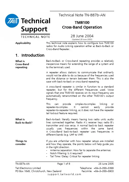
Technical Note TN-887b-ANTM8100Cross-Band Operation28 June 2004(Updated 28 June 2005)ApplicabilityThis technical note explains how to configure two TM8100radios for Audio Linking operation either as Back-to-Back or Cross-Band Repeater.1. IntroductionWhat is Cross-Band repeatingBack-to-Back or Cross-band repeating provides a relatively inexpensive means for extending the range of a system and to the terminals used.A repeater allows stations to communicate that ordinarily would not be able to do so because of the frequencies used and the distance or terrain between them. This is also the case with back-to-back or cross-band repeating.A cross-band repeater is similar in function to a standard repeater, but for the different frequencies used. Voice signals that one TM8100 receives on its input frequency are automatically retransmitted on the other TM8100’s output frequency.This can provide simplex-to-simplex linking or repeater-to-simplex. It cannot easily provide repeater-to-repeater linking, as it does not have the repeater tail lockout feature required.What isBack-to-Back?Back-to-back literally means having two radio units audio lines connected together. Radio A’s receiver keys radio B’s transmitter and vice versa. A normal back-to back repeater usually uses frequencies within the same band.A Cross-Band back-to-back repeater uses frequencies in different bands (e.g. UHF to VHF)Things to considerIf you are unfamiliar with how repeater setups are installed and how they operate, the points below will help guide you in the right direction.- Antenna separation: How far to separate the antennas - Notch Filtering: Is it required?- Tail Time / Delay: Critical for repeater linkingTN-887b-ANPage 1 of 628 June 20052. InterfacingConfigure the Cross-Band interconnect cable as indicated in the diagram below.Configuring the Cross-Band Interconnect CableFor voice linking applications the value of Cc should be at least 100ηF.For data linking applications the recommended value for Cc is 4.7µF.In either case the capacitor needs to be non-polarised.The simplest way to create a 600-Ohm resistor is by using two 1K2Ω resistors in parallel.The resistor(s) and capacitor can then be mounted inside each DB-15 cover.TMAA04-04Manufactured by TEL this cable provides the connections defined in this Technical Note along with the R/C network for voice applications. The SMD capacitor can be changed for a 4.7µF for data interfacing.This cable also has provisions for a MAX232 IC and 78L05regulator for other RS-232 applications instead.TN-887b-AN Page 2 of 6 28 June 20053. Radio ProgrammingProgramming Instructions After defining the separate radio’s Transmit and Receive channel parameters, the following settings need to be programmed to enable cross-band operation:In the PC Application menu:PTT > External PTT(1) > Advanced EPTT1• PTT Transmission Type should be Voice.• PTT Priority should be Highest.Note: PTT or EPTT(2) priority may need changing.• Audio Source should be Audio Tap In.Repeater Transmit Tail (Prog App v2.90 and Firmware v2.09 onwards)If desired the Transmitter can have a ‘tail’ by defining the PTT Deactivation Delay time up to 1000ms (see above). This duration is the same as ‘holding PTT in’ so any signalling (such as CTCSS) is still present.The CTCSS can be configured using the Networks > Basic Settings > Subaudible Signalling tab.• Leave the Reverse Tone Burst Duration at about 130ms to ensure the mobile receiving radios mute promptly. • If desired, set a further transmitter tail by setting the Lead-Out Delay field for any duration up to 1000msNOTE: This duration does not encode any subaudible signalling.The same functionality can be attained using the DCS fieldsTN-887b-AN Page 3 of 6 28 June 2005Programmable I/ODigital TabPin Direction Label Action Active DebounceSignalState Mirrored ToAUX_GPI1 Input PTT_INExternal PTT1Low 2 None None AUX_GPIO5Output BUSYSignalling Audio MuteStatusLowNone None NoneRepeater Transmit TailIf the transmitter requires a ‘tail’ and uses CTCSS this can be configured using the Networks > Basic Settings >Subaudible Signalling tab.• Leave the Reverse Tone Burst Duration at about 130ms to ensure the mobile receiving radios mute promptly. • Set a transmitter tail by setting the Lead-Out Delay field for any duration up to 1000ms.NOTE: This duration does not encode any subaudible signalling. The same functionality can be attained using the DCS fields.TN-887b-AN Page 4 of 6 28 June 2005Programmable I/OAudio TabRx/PTT TypeTap In Tap In Type Tap In Unmute Tap Out Tap Out TypeTap Out UnmuteRx None A-Bypass In On PTT R7 D-Split Busy Detect + SubaudEPTT1T5A-Bypass InOn PTTNoneC-Bypass OutOn PTTOperational Testing• Inject into the receiving radio an on-channel RF signal of –70 dBm with a 1 KHz tone and the deviation set to either 3 KHz for a Wideband channel or 1.5 KHz for a Narrowband channel.• The transmitting radio’s deviation should be:±3KHz (± 200Hz) on a 25KHz Wideband channel or ±1.5KHz (± 200Hz) on a 12.5KHz Narrowband channel.TN-887b-AN Page 5 of 6 28 June 2005Compliance Issues If the link is a fixed site, RF compliance may need to be obtained and / or monies to be paid to regulatory bodies.CSO Instruction Please pass this information onto the field supporttechnicians, technical support engineers and appropriatedealers.4. Issuing AuthorityName and Position of Issuing Officer BarryCratesTechnical Support Team Leader - TerminalsConfidentiality Confidential – This message or document containsproprietary information intended only for the person(s) ororganisation(s) to whom it is addressed. All Recipients arelegally obliged to not disclose Tait technological or businessinformation to any persons or organisations without thewritten permission of Tait.Distribution Level Tait Only, Accredited Service Centre System Integrator,Accredited Service Centre and System IntegratorDocument History Original Release - TN-NSC078January 2004 BPModified to TEL TN format forpublishing to global audience.28 June 2004 BLCModifiedlayoutUpdated ‘tail’ timer options March 200528 June 2005GCBGCBTN-887b-AN Page 6 of 6 28 June 2005。
M8100报文记录分析及故障录波装置使用说明书广州思唯奇计算机科技有限公司目录第一章产品介绍 (1)1.1概述 (1)1.2产品特点 (1)1.3技术参数 (1)1.4应用方案 (3)1.4.1GOOSE、MMS分析方案 (3)1.4.2GOOSE、MMS、SV分析方案 (4)第二章设备安装说明 (5)2.1使用环境 (5)2.2供电电源 (5)2.3设备安装 (5)2.4设备组屏安装 (6)第三章硬件使用说明 (8)3.1外观说明 (8)3.1.1设备正面说明 (8)3.1.2设备背面说明 (8)3.2液晶屏显示说明 (8)3.3LED指示灯说明 (9)第四章软件使用说明 (10)4.1软件安装及登陆说明 (10)4.1.1软件安装 (10)4.1.2软件登录 (11)4.1.3站点设置向导 (11)4.2软件界面操作说明 (14)4.2.1软件主界面说明 (14)4.2.2IED列表操作说明 (14)4.2.3报文分析窗口操作说明 (15)4.3功能菜单操作说明 (28)4.3.1文件菜单操作说明 (28)4.3.2站点管理菜单操作说明 (28)4.3.3系统设置菜单操作说明 (30)4.3.4故障录波菜单操作说明 (32)4.5故障录波管理界面操作说明 (33)4.5.1录波通道、间隔配置 (33)4.5.2定值设置 (36)4.5.3实时录波文件 (40)4.5.4实时值监测 (41)4.5.5历史录波文件查询 (43)4.6故障录波离线分析软件操作说明 (44)4.6.1主界面 (44)4.6.2菜单栏 (44)4.6.3工具栏 (54)4.6.4数据信息显示区和数据波形显示区 (55)第一章产品介绍1.1 概述随着IEC61850标准的推行,数字化变电站相关技术日益完善,数字化变电站已经进入了大规模实用阶段。
在数字化变电站中,采用数字传输技术替代了常规变电站中沿用多年的模拟量传输,完成变电站各IED设备之间的实时信息交换,为实现数据共享和设备的互操作性提供了必要的技术基础。
前言感谢您选用了浙江恒强科技有限公司生产的无缝针织内衣机。
为了让您安全、有效的使用无缝针织内衣机的控制软件,请您仔细阅读本操作手册,以确保正确的操作使用无缝针织内衣机。
此外,请将本操作手册妥善保存在安全地点,以便随时查阅。
目录一、安全注意事项二、操作界面说明 (3)三、机器测试 (4)1、选针器测试 (5)2、气阀测试 (7)3、步进电机测试 (8)4、输入信号测试 (10)四、机器设置 (11)1、选针器设置 (12)2、气阀设置 (12)3、电机设置 (13)4、系统设置 (14)5、系统维护 (14)5-1、查看程序版本 (15)5-2、程序升级 (16)5-3、恢复缺省参数 (16)5-4、输入图形文件 (17)5-5、输出配置文件 (18)5-6、输入配置文件 (18)五、文件管理 (18)1、输入花型文件 (19)2、输出花型文件 (19)3、选择花型文件 (19)4-预览花型文件 (20)六、进入编织 (20)七、联机帮助 (20)一、安全注意事项使用本产品时,为了减少火灾、触电或人员伤亡的危险,应始终遵守下列基本的安全预防措施。
操作界面如图1所示:图1:液晶屏的开关按钮,按一下关闭液晶,再按打开液晶。
、:调节液晶屏的亮度按钮。
:主菜单。
:帮助键。
ESC:为后退命令。
F1:限速F2:单幅停车F3:降机头F4:抬机头F5:密度调节,F6:报警开关F7:停链F8:抬梭F9:复位F10:快进三、机器测试按键,进入主菜单,如图2所示。
图2按上、下方向键选择1-机器测试,再按下ENTER进入测试菜单,如图3所示:图31、选针器测试:在测试菜单中按上、下方向键选择1-选针器测试,再按下ENTER进入选针器测试界面(如图4所示)。
完成测试项目的选择后按ENTER键开始测试。
图4全选(F1):表示8路选针器一起测试。
在选针器测试界面中按下全选(F1)按键(如图5所示),即可实现16个选针器同时测试。
(1)锁键:(只DT730有)用户可以防止信息通过话机泄漏给其他人员。
(2)呼叫指示灯:对于SV8100,当有电话呼入是指示灯快闪,有留言时,指示灯慢闪。
(3)LCD :LCD (液晶显示屏) 显示日期,时间和软键的操作。
(4)退出键用户按该键可以退出屏幕模式(5)软功能键屏幕下方的软功能根据屏幕上的显示功能来使用。
(6)帮助键用户可以按帮助键和其它键来检查该键被定义为外线,分机或功能键(7)可编程单触键使用电话机,wed/pcpro可以定义这些键为分机、外线、功能键(8)再呼叫叫(9)功能键用于激活话机设置的各功能。
(10)应答键该键的LED灯亮是,按该键应答等待的呼叫。
(11)Mic 键按该键LED 灯亮时,功能被激活,免提可以送话。
(12)菜单键通过按该键,用户可以使用多种不常用功能(比如终端设置,下载和进入XML的应用。
(13)导航键使用该键可以方便的使用多种功能(14)进入键DTT330/DTT730 话机对经常使用的功能有快捷菜单。
通过按进入键,用户能使用快捷菜单。
(15)重拨键(末码重拨,速拨,分机、组)按该键使用重拨功能。
按重拨键,按上下键查找已播出的号码。
(16)免提键控制内置扬声器,用于免提拨号和监听。
LED灯亮时功能激活。
(17)转接键用于转接电话(18)保留键SV8100简单操作与使用打电话:摘机拨加电话号码代接电话:摘机拨键转电话:通话中按键拨分机号码挂机普通话机转电话:有键按键拨分机号码,没用键的拍叉簧拨分机号挂机重拨末次外线电话:不摘机状态左键摘机通话保留:如在通话中有另一个电话呼入可按再按键键转出电话再按键键接回前面保留的电话专用话机分机单触键清除单触键:852 +000 清除+设置设分机单触键:851 分机号码设置设外部电话单触键:851 键+单触键电话会议专用话机先设一个会议键,按键按键1.通话中按23..对方应答后按两次建立会议要增加会议用户重复以上步骤普通话机:1.通话中拍拨82623.对方应答后按两次建立会议要增加会议用户重复以上步骤转移到分机或外线设置或取消:摘机+服务码 + 1(设定)或 + 0(取消)+目标分机号码 + 挂机服务码: 842. 呼叫转移双方振铃 843.遇忙转移 844。