JellyFish中文说明书
- 格式:doc
- 大小:601.00 KB
- 文档页数:13

F Two Operating Manual操作手册F Two Active SubwooferGeneral descriptionThe G enelec F Two is a very compact active subwoofer designed to comple-ment up to five Genelec G One or G Two active loudspeakers as a .1 / LFE channel subwoofer in a 5.1 system or a pair of the slightly bigger G Threes. Linked together two F Two’s can also be used with G Fours. The F Two extends the system’s bass response down to 27 Hz and integrates perfectly with the main loudspeakers in any environment. The playback level for the whole system is conveniently controlled by the wireless volume control provided with the subwoofer. A wired volume control is available as an option.The F Two has integrated bass manage-ment for the two output channels which directs frequencies below 85 Hz to the subwoofer and higher frequencies through the output connectors to the main loud-speakers. When using the subwoofer for the .1/LFE channel of a multichannel system, we recommend that bass manage-ment is done in the processor or receiver and only the LFE channel is connected to the subwoofer.InstallationBefore connecting the audio signals, ensure that all equipment is switched off.As the F Two contains its own amplifier, no separate power amplifier is needed. Never connect the F Two to the loudspeaker out-puts of a power amplifier, integrated ampli-fier or receiver.Please follow the steps listed below for a succesful setting up of the subwoofer:1. Check the contents of the shipment.in addition to the subwoofer, there is awireless remote control, a mains cable,an IR extension cable and a Quick SetupGuide.2. Pull out the battery insulating strip fromthe underside of the remote control asshown in figure 1. This strip insulates thebattery from the contacts on the remotecontrol during shipping and the remotecontrol does not function before it isremoved.3. Place the subwoofer in its position.4. Connect audio cables from your signalsource(s). You can connect up to twodigital audio sources and two analogaudio sources.5. Connect the main loudspeakers tothe output connectors of the subwoofer.You can use either balanced XLR orunbalanced RCA connectors.6. Set the “LEVEL +10” and “-10 dB”switches on the subwoofer and mainloudspeakers according to Table 2 on thismanual.7. Adjust the phase of the subwoofer asinstructed in this manual and the QuickSetup Guide.8. Use test recordings and familiar musicpieces to judge the sound balance. Usethe “SUBWOOFER LEVEL” rotary controland the “BASS ROLL-OFF” dip switchesto fine-tune the balance. If this fails,consider relocating the subwoofer.Operating EnvironmentThe F Two subwoofer is designed forindoor use only. The ambient temperatureshould be 15-35 °C (50-95 °F) and the rela-tive humidity 20-80 %. Condensation is notallowed. If it has been stored or transportedin a cool environment, the product must beallowed to warm up in its packing to theambient temperature before connectingmains power.ConnectorsThe F Two is equipped with both analogand digital signal input connectors, thatcan be used simultaneously to connectup to four audio sources (two analog, twodigital). Switching between sources is donewith the Select button on the connectorpanel or with the “<” and “>” buttons onthe remote control. The colour of the LEDlight on the subwoofer enclosure indicateswhich source is selected.Analog Input ConnectorsThe F Two has two stereo inputs (3.5 mmjack and L/R RCA connectors) and an LFE/LINK RCA connector. The stereo inputsare parallel, so you can connect two audiosources at the same time, just play onlyone of them at a time. The Select functiondoes not work between these two inputs.The LFE/LINK input is used for the LFEFigure 1. Removing the battery insulating stripfrom the remote controlFigure 2. Connectors and controls of the F Two.(.1) signal in a 2.1 or 5.1 channel sound system or as the signal input in a multiple subwoofer system (see chapter Using Mul-tiple Subwoofers). The LFE/LINK input has a 120 Hz low pass filter, so it is not suitable for full frequency range signals.Digital Input ConnectorsThe F Two has two digital signal input con-nectors, one coaxial and one optical, thataccept stereo PCM format digital signal.You can connect two digital sources andswitch between them using the Selectfunction.Analog Output ConnectorsThe F Two has two pairs of analog stereoL/R output connectors, one with RCA con-nectors and the other with balanced XLRmale connectors. Connect signal cablesfrom these connectors to the main speak-ers. Both connector pairs carry the sameFigure 3. Audio cablingsignal so you can use main speakers with either RCA or XLR input connectors. These outputs are high pass filtered at 85 Hz (See chapter Bass Management). Additionally, the LINK RCA output provides a summed signal of both channels. Use this connector as a signal output to the next subwoofer when you want to connect several sub-woofers together. See chapter “Using Mul-tiple Subwoofers” for more information.System Volume Control ConnectorThis connector allows connecting the G enelec 9310A Wired Volume Control which is available as an accessory. When connected, the 9310A controls the volume of the whole system, including the main speakers.IR IN ConnectorIf the F Two is used with an infrared type remote control (see chapter Use with IR Remote Controls) and the desired location of the subwoofer does not allow an unob-structed line of sight to the receiver located next to the LED in one of subwoofer’s feet, the IR extension cable provided with the subwoofer can be connected here. The receiver end of the cable is then brought to a location where the IR remote control reception works conveniently, for instance close to the IR receiver of a television set when using the subwoofer and speakers with a TV .Subwoofer placement Bass Roll-OffNear a wall -2 dB In a corner-4 dBTable 1. Suggested Bass Roll-Off settings in typical situationsFigure 4. F Two remote controlMain loudspeaker model F Two Level Dip switch setting -10 dB switch+10 dB switchG One A OFF OFF G One BOFF OFF G One B -10 dB Dip ON ON OFF G Two A OFF OFF G Two BOFF OFF G Two B -10 dB Dip ONON OFF G Three AOFF OFF G Three A +10 Dip ON OFF ON G Three BOFF OFF G Three B -10 Dip ONON OFF G Four AOFF OFF G Four A +10 dB Dip ONOFF ON 8010AOFF ON 8010A -10 dB Dip ONOFF OFF 8020A OFF ON 8020B OFF ON 8020C OFF ON 8020D OFF ON 8030A OFF ON 8030B OFF ON 8030C OFF ON 8040AOFF ON 8040B OFF ON M030OFFONTable 2. Suggested Level switch settings with different main loudspeakersFunctions And ControlsHT ModeTurn this switch to “ON” when you connect a sound source with its own volume control to the analog inputs of the F Two. In this mode the volume control of the F Two does not have effect on the analog signals. However, it works with the digital inputs, so you can use them to connect other signal sources.ISS Sensitivity LowIf the Intelligent Signal Sensing (ISS) func-tion switches the subwoofer on when there is no audio signal present, turning thisswitch to “ON” reduces the triggering sen-sitivity of the function.ISSThe Intelligent Signal Sensing (ISS) func-tion monitors the audio signal fed to the subwoofer. If there is no signal for approxi-mately 45 minutes, the function switches the subwoofer to Standby mode, reduc-ing the power consumption to less than 0.5 Watts. When the signal resumes, the subwoofer powers up again. There is a slight delay in the automatic powering up. In those environments where the subwoofer is required to be on all of the time, the ISSVOLUME UP VOLUME DOWN SELECT BUTTONSMUTEPOWERfunction can be disabled by setting the “ISS” switch to the “OFF” position. Then the subwoofer is continuously powered and can be turned off using the power button on the remote control or connector panel.LED OffThis switch deactivates the status indicator LED on the “foot” of the subwoofer.Roll-OffThese two switches attenuate the sub-woofer’s bass response. At 27 Hz the attenuation levels are -2, -4 and -6 dB (both switches “ON”).PhaseThese two switches provide phase adjust-ment for the subwoofer in -90 degree incre-ments. See chapter “Phase Alignment”.LinkThis switch selects the analog inputs and disables input channel selection. In addi-tion, it disables the remote control and sets the subwoofer’s level to maximum. Set this switch to “ON”, when using the subwoofer as a “slave” in a multiple subwoofer system. See chapter “Using Multiple Subwoofers”.LevelThese two switches allow adjusting the subwoofer’s level by -10 dB or +10 dB, providing level matching with different main speaker models. See Table 2 for some examples.Subwoofer LevelThis rotary adjustment adjusts the play-back level of the subwoofer. The level is increased by turning the adjustment clock-wise and reduced by turning it counter-clockwise.SelectThis button allows signal input selection between the two digital inputs and the analog input and initiation of the match-ing procedure for IR remote controls (see Matching IR Remote Controls).PowerThis button switches the subwoofer between Standby and Power mode. Note that this button does not completely dis-connect the subwoofer from the mains power. If this is necessary, the subwoofer’s mains cable must be disconnected. This button can also be used for restoring the factory settings by keeping it depressed for10 - 15 seconds. This returns the volumesetting on the remote control to factorylevel and deletes possible remote controlpairing and IR remote control matching.Also the source selection returns to auto-matic, which is the factory setting.Positioning In The RoomThe placement of the subwoofer in theroom affects the overall frequency responseand sound level of the system dramatically,as at low frequencies the effects of theroom are strong. Even a slight change inthe location of the subwoofer can cause amarked difference in the frequency balanceand often patient and methodical experi-mentation and testing is needed to find theoptimum placement.The placement will also affect the bassroll-off rate and the phase differencebetween the main loudspeakers and thesubwoofer. These effects can be compen-sated using the controls in the subwooferbut we recommend that at first you leavethe switches untouched and concentrateon finding the position where the subwoofergives the smoothest response, and only thenuse the controls to fine-tune the balance andphase alignment between the subwooferand the main loudspeakers.Start by placing the subwoofer close to thecenter of the front wall. We recommenda distance of less than 60 cm / 24” to thewall. This position gives increased acous-tic loading and sound pressure level due tothe proximity of the front wall and floor. Ide-ally the subwoofer and main loudspeakersshould be positioned symmetrically and atan equal distance from the listening position.If the frequency balance is not quite right,try moving the subwoofer to the left or rightalong the wall so that different room modesare excited at different levels. Positioningthe subwoofer close to a corner will boostthe bass level at lower frequencies and maycause asymmetrical spatial imaging.ISS TM AutostartThe automatic power saving function ISS(Intelligent Signal Sensing) can be activatedby setting the “ISS” switch on the connec-tor panel to “ON.” Automatic poweringdown to standby mode happens after acertain time when playback has ended. Thepower consumption in standby mode istypically less than 0.5 watts. Playback willautomatically resume once an input signalis detected from any source.Alternatively, the subwoofer can be acti-vated by pushing any button on the remotecontrol.There is a slight delay in the automaticpowering up. If this is undesirable, the ISS TMfunction can be disabled by setting the “ISS”switch on the connector panel to “OFF.” Inthis mode, the subwoofer is powered on andoff using the remote control or the powerbutton on the connector panel.The “ISS SENSITIVITY LOW” switchlowers the triggering sensitivity of theISS function. This can be necessary if thesubwoofer “wakes up” even if there is noaudio signal.Setting The Playback LevelThe “LEVEL +10 dB and LEVEL -10 dB”switches and the rotary “SUBWOOFERLEVEL” level adjustment can be used formatching the subwoofer’s playback levelwith the main loudspeakers (See Table 2).Fine tuning can be done with the rotaryadjustment knob.Setting The Bass Roll-OffSwitchesThe acoustic response of the subwoofermay have to be matched to the charac-teristics of the room and the positioning inwhich it will be used (see Table 1). To adjustthe subwoofer to match these character-istics use the ‘’BASS ROLL-OFF’ controlswitches located on the connector panel.When all Roll-Off switches are ‘OFF’, a flatanechoic response is obtained.Setting The Phase ControlThe effect of incorrect phase alignmentbetween the main loudspeakers andthe subwoofer is a drop in the frequencyresponse of the whole system at the mainloudspeaker / subwoofer crossover fre-quency. The phase difference between themain loudspeakers and subwoofer at thelistening position is dependent upon thedistance from the listener to the subwooferin relation to the main loudspeakers. Toavoid phase differences between theleft and right main loudspeakers andthe subwoofer, the subwoofer should beplaced close to the center of the front loud-speaker array.Two phase matching switches allow com-pensation for incorrect phase alignment.Four settings are provided between 0° and-270°.Coarse Phase CorrectionMethodConnect an audio frequency signal gen-erator to a signal input on the subwoofer which has a main loudspeaker connected to the corresponding “OUT” connector. If the loudspeakers are placed at differ-ent distances from the listening position, choose the loudspeaker that is nearer.Set the generator to 85 Hz. If a signal gen-erator is not available, it is possible to use an audio test recording which has a test frequency in the range 70 Hz to 100 Hz. Suitable test signals can be downloaded at and found in some smart phones.Toggle the -180° phaseswitch ‘ON’ and ‘OFF’ andset it to the position whichgives the lowest soundlevel at the listening posi-tion.Next toggle the -90°phaseswitch ‘ON’ and ‘OFF’,and again set it to theposition which gives thelowest sound level.Finally, set the -180°phaseswitch to the opposite set-ting.Matching IR RemoteControlsThe F Two subwoofer can be used with most IR remote controls, providing con-venient use with, for instance, the remote control of a TV set when connected to it via a fixed level digital signal input. Turn the subwoofer upside down so you can easily reach the “Select” button on the subwoof-er’s connector and the status indicator LED on the subwoofer’s foot is visible. The IR receiver is located in the LED. Note that the “Select” buttons on the RF remote control provided with the subwoofer do not actu-ate the matching.The matching procedure is as follows:• Keep the “Select” button on the subwoofer depressed until the status indicator LED starts blinking red.• Choose the button on the remotecontrol that you want to actuate “volumeup” function. Keep it depressed until theLED stops blinking. With some remotecontrols pressing the button multipletimes works better.• Now the LED blinks green, indicatingthat the button for “volume down” can beselected. Follow the procedure describedabove.• Next the LED blinks blue for selection ofthe button for “Select” button.• Yellow LED indicates the selection of“Mute” button.• Magenta LED indicates the selection of“Power” button.A short press on the “Select” button allowsyou to skip a step in the procedure, if youdo not want to “teach” all the commandslisted above. If you want to interrupt theprocedure, press “Select” for approxi-mately two seconds. This saves the set-tings made so far. If you don’t want tosave the settings, press the Power buttonfor two seconds. This will also delete thematching settings done by that point. If youwant to change the matched buttons, justredo the matching process.Matching The RF RemoteControl To The SubwooferThe remote controls delivered with F Twosubwoofers will function with any other F Twosubwoofer as well. If this is not desirable, forinstance when there are several F Two sub-woofers in the same premises, and the userwishes to avoid the situation that more thanone subwoofer reacts to the commandsgiven by each remote control, the remotecontrols can be matched to operate only onesubwoofer.1. Press and hold down the “Power” and“Select “ buttons on the subwoofer until theLED starts blinking white.2. While the LED is blinking, first pressand hold down the volume “+“ button onthe remote control and then the volume “-“button. Keep both buttons pressed for a fewseconds until the status indicator LED on thesubwoofer stops blinking. This indicates thatmatching is completed and the matchingoperation ends automatically.Now the subwoofer should only respondto commands given by the matched remotecontrol, and respectively, the matchedremote control should not work with otherF Two units. For cancelling the matchingoperation while the LED is blinking, pressand hold down the ”Power” button on thesubwoofer for two seconds. If you wish toundo a matching completely, press and holddown the ”Power” button on the subwooferfor ten seconds.NOTE: In some cases the local WiFinetwork can cause problems with the RFremote control, if they operate on the samewavelength. We recommend the use of an IRremote control in these cases.Using Multiple SubwoofersThe Genelec F Two subwoofer is equippedwith an LFE/LINK output connector to pro-vide an easy way of coupling two or moresubwoofers together in high SPL applica-tions, for instance when using the subwoof-ers with Genelec G Four active loudspeak-ers. Connected as described below, the“master” subwoofer controls the volumeof all subwoofers linked to it through thisconnector.Connect an RCA cable from the LINK con-nector of the “master” subwoofer to whichthe main loudspeakers are connected, to theLFE / LINK connector of the other, “slave”subwoofer and turn the LINK dip switch onthe “slave” subwoofer to “ON”.In the LINK mode, the subwoofer volumeis automatically set to maximum and the“slave” subwoofer only reacts to the poweron/off commands given with a remotecontrol. It follows the volume adjustmentand source channel selection done in the“master” subwoofer.When two subwoofers connected in thisway are positioned close to one another,bass level increases by 6 dB. Three sub-woofers give an SPL increase of 9.5 dB andfour subwoofers 12 dB compared to a singlesubwoofer.The rotary “SUBWOOFER LEVEL” adjust-ment knob should be set in the same posi-tion as that of the “master” subwoofer unlessthe subwoofers are placed in very differentpositions acoustically, for example one ina corner and one far from corners. In suchcase, it is advisable to measure the loudnessof each subwoofer separately and adjustthem individually for correct balance.Phase and Bass Roll-Off adjustments shouldbe done individually for each subwoofer in thechain, especially if they are not placed closetogether. To check the phase alignment forthe “master” subwoofer switch off the “slave”subwoofer and follow the instructions given inthe previous sections.To adjust the phase alignment of thePHASEPHASEPHASE“slave” subwoofer, you need to switch off the “master” subwoofer, connect a signal cable from one of the “slave” subwoofer’s output connectors to the corresponding loudspeaker and switch the LINK switch to “OFF”. This effectively changes the “slave” to “master” mode and the phase adjustment can be carried out. Return the connections and LINK setting on the “slave” subwoofer back to the “ON” setting after completing the adjustment.Safety ConsiderationsThe Genelec F Two complies with interna-tional safety standards. However, to ensure safe operation and maintain the equipment in safe operating condition the following warnings and cautions must be observed.• Do not use this product with an unearthed mains cable or a mains connection without the protective earth contact as this may lead to personal injury.• Danger of explosion if battery is incorrectly replaced. Replace only with the same or equivalent type.• The battery shall not be exposed to excessive heat such as sunshine, fire or the like.• Servicing and adjustment must only be performed by qualified service personnel. • Opening the subwoofer is strictly prohibited except by qualified service personnel.• Do not expose the subwoofer to water or moisture. Do not place any objects filled with liquid, such as vases on the subwoofer or near it.Note that the amplifier is not completely disconnected from the AC mains service unless the mains cable is removed from the amplifier or the mains outlet.Warning!This equipment is capable of deliver-ing sound pressure levels in excess of 85 dB, which may cause permanent hearing damage.Compliance To FCC RulesRemote controlThis device complies with Part 15 of the FCC Rules. Operation is subject to the fol-lowing two conditions: (1) this device may not cause harmful inter-ference, and (2) this device must acceptany interference received, including inter-ference that may cause undesired opera-tion. This product emits radio frequencyenergy, but the radiated output power ofthis device is below FCC radio frequencyexposure limits. This equipment complieswith FCC RF radiation exposure limits forthfor an uncontrolled environment. Neverthe-less, the device should be used in such amanner that the potential for human con-tact with the antenna during normal opera-tion is minimized.Changes or modifications not expresslyapproved by the party responsible for com-pliance could void the user’s authority tooperate the equipment.SubwooferThis device complies with part 15 of theFCC Rules. Operation is subject to the fol-lowing two conditions:This device may not cause harmful inter-ference, and this device must accept anyinterference received, including interfer-ence that may cause undesired operation.Note: This equipment has been tested andfound to comply with the limits for a ClassB digital device, pursuant to part 15 ofthe FCC Rules. These limits are designedto provide reasonable protection againstharmful interference in a residential instal-lation. This equipment generates, uses andcan radiate radio frequency energy and, ifnot installed and used in accordance withthe instructions, may cause harmful inter-ference to radio communications. However,there is no guarantee that interference willnot occur in a particular installation. If thisequipment does cause harmful interferenceto radio or television reception, which canbe determined by turning the equipmentoff and on, the user is encouraged to try tocorrect the interference by one or more ofthe following measures:• Reorient or relocate the receivingantenna.• Increase the separation between theequipment and receiver.• Connect the equipment into an outleton a circuit different from that to which thereceiver is connected.• Consult the dealer or an experiencedradio/TV technician for help.Figure 5. Changing the remote control batteryModifications not expressly approved bythe manufacturer could void the user’sauthority to operate the equipment underFCC rules.Changing The RemoteControl BatteryThe remote control battery can be changedby turning the battery cover on the backof the remote control anticlockwise. Usea small screwdriver under the right side ofthe battery (see figure 5) to wedge the bat-tery out. Replace the battery with a similarCR2032 type battery. Insert the battery withthe left side first as shown in figure 4 andclose the battery cover.Take the used battery to your local bat-tery recycling point. Under no circumstancesshould the battery be disposed with generaldry waste.MaintenanceThere are no user serviceable parts insidethe subwoofer. Any maintenance of the unitmust only be performed by qualified servicepersonnel.GuaranteeThis product is supplied with two yearguarantee against manufacturing faults ordefects that might alter the performance ofthe unit. By registering your product at:You can get an additional three year guaran-tee that covers the spare parts.Operating Manual F TwoF Two 有源超低音音箱概述真力 F Two 是一款紧凑型有源超低音音箱,可以作为多声道音响系统中的LFE 声道搭配5只真力G One 或者G Two 主动式有源音箱使用,或者搭配一对更大的G Three 使用。

Alphacool's Core product series is characterized by high quality,outstanding performance and the uniform and functional design language.•Optimised fin structure enables very good water flow &increase of cooling surface•Modified jet plate ensures optimal distribution of the water on the cooling fins•Visually calm & simple design with digital aRGB illumination•Chrome-plated copper coolerV. 1.000 // 03.2023Alphacool Core Geforce RTX 4080 Reference Design with BackplateAlphacool article number: 13439- Nvidia Geforce RTX 4080 Reference Design- INNO3D GeForce RTX 4080 X3 OC, 16GB GDDR6X, HDMI, 3x DP- INNO3D GeForce RTX 4080 X3, 16GB GDDR6X, HDMI, 3x DP- INNO3D GeForce RTX 4080 iCHILL X3, 16GB GDDR6X, HDMI, 3x DP (C40803-166XX-187049H)- PNY GeForce RTX 4080 16GB XLR8 Gaming Verto Epic-X RGB Overclocked Triple Fan, 16GB GDDR6X, HDMI, 3x DP (VCG408016TFXXPB1-O) (*) - PNY GeForce RTX 4080 16GB XLR8 Gaming Verto Epic-X RGB Triple Fan, 16GB GDDR6X, HDMI, 3x DP (VCG408016TFXXPB1) (*)- PNY GeForce RTX 4080 16GB Verto Triple Fan, 16GB GDDR6X, HDMI, 3x DP (VCG408016TFXPB1) (*)(* The cooler is compatible with the GPU, but the rear part of the PCB is not covered. This has no negative effect on the cooling performance!)1x Core Geforce RTX 4080 Reference Design Cooler 1x Backplate4x 8x8x1mm Pad3x 40x15x1mm Pad2x 84x8x1mm Pad1x Thermal Grease1x Putty tool4x M2x5mm Screw4x EVA Washer 1x Screwdriver1x 45x45x3mm GPU-Pad 3x 56x8x3mm Pad2x 84x8x3mm Pad7x M2x10mm Screw1x PCI Bracket1x ARGB Adapter2x G1/4 Plug1x Plug toolAlphacool's Core product series is characterized by high quality, outstanding performance and the uniform and functional design language.The copper cooler which, like the end terminal, is milled from a single piece of copper and is the core of this cooler. The fine workmanship, paired with the hard and resistant chrome plating covering the entire copper cooler, meet the highest quality standards. The chrome-plated brass G1/4" threads integrated on both sides stand out visually from the terminal. They are a central feature of the new design language that will be evident in all products in the Core series.The aluminum backplate adapted to the design, together with the terminal, makes up the entire unit and enhances the back of the cooler with a clean and homogeneous look. The lighting consists of digitally addressable RGB LEDs, which illuminate the entire cooler evenly and effectively.The technical advancements can be seen in the water supply to the jet plate as well as in the optimization of the jet plate itself. The jet plate has been completely redesigned based on many simulations and practical tests in cooperation with board partners. The fin thickness and spacing have been enhanced, the cooling surface has been increased and the water flow to the core components with the greatest heat output has been optimized. The enclosed special soft thermal pads with up to 7 W/mK adapt perfectly to even the smallest tolerances.Drawing。

自拍杆产品使用说明书Bluetooth Selfie Stick Production User Manual如何安装电池/Change Batteries本产品采用2节AA电池,易于更换。
更换电池时务必按照以下步骤进行,以免造成损坏。
步骤①:将电池负极向内装入手柄。
步骤②:将后盖对准手柄尾部,稍用力向下压,并对齐螺纹。
步骤③:向顺时针方向旋转即可安装好灯头。
注意:拧紧时不能太用力,以免损坏手柄。
This product uses2AA batteries,easy replacement.To Avoid damage,please follow below instructions when replacing the batteries.Step①:put the batteries into the handle,anode outward.Step②:the cover alignment of the tail of the handle,slightly downward pressure, and align the thread.Step③:rotate it clockwise,ATTENTION:please tightening up the cap slightly, not too hard,otherwise it may cause damage.遥控手柄按键说明/Instruction of Remote Joystick蓝牙手柄操作说明/Bluetooth Selfie stick operating instructions第一步:按住电源键3秒,LED灯将会点亮,并进入闪烁状态,遥控器自动进入蓝牙配对状态。
第二步:开启手机蓝牙功能并进入搜索状态,当出现“PPY Shutter-II"时,点击“PPY Shutter-II"进行自动配对连接,连接成功后,遥控器的LED熄灭。

The FUZZ GOD IIMy heartiest congratulations to you for purchasing a Red Witch FUZZ GOD II! Prepare to unleash your omnipotence!!The device you are now holding in your hands offers several unique features, which you cannotfind anywhere else. I strongly recommend that you read on to discover the full potential of your new pedal!ControlsVolume - This controls the output Volume - convert the masses quietly or with blasting trumpets (err, guitars). You will find that as you turn the control through the last 20% of its rotation a treble boost is added. Sizzly!Fuzz - From a gentle break up to a singing beam of fuzz - you decide Wind back your guitars volume control to clean things up. When the sputter control is counter clockwise, this control will crackle a little when turned, –it’s ok, don’t be alarmed, there’s nothing to be afraid of.Wrath - All gods have it and the Lord of the Fuzz is no different - click this only to smite the most brazen of unbelievers.When engaged (by depressing the lightning bolt foot switch) you can dial up all manner of destruction; SubOctave Thunder, eternally sustained notes, squealing high frequency note corruption and a myriad number of other terrifying tones.Utter Maddness.This control interacts with the fuzz and sputter control. Try adjusting you guitars volume as well to open an even broaderpalette of chaos!! We recommend that you disengage this control when bypassing the pedal – to avoid any possibility ofbleed oscillation.Sputter - Choose from a smooth singing fuzz to a ragged, rough, sputty gated mess andanything in between. This control allows you to se t the units “sweet spot”. You’ll find that spot between 12 o’clock and5 o’clock . Ragged sputtsville kicks in between 7 o’clock and 11 o’clock. You’ll find that it’s best to tweak this sweet spot eachtime you set up to play. The wonders of magical Sinful Silicon goodness! This control will crackle when turned –it’s changing adc bias –and that’s ok.Awaken - A super sturdy true bypass switch to engage the Fuzz God effect.Lightning Bolts - Engage this foot switch to incur the wrath of the Fuzz God – crazed Oscillation and octavizationeffects.Lightning toggle switch - Engage this to double your gain. Heh. Ahhhh ……heh. HEH.Ear toggle switch- Engage this switch to boost treble frequencies.Internal trim pot–inside your unit you’ll see a Blue trim pot with a phillips head screw slot in it’s back. This adjust themaster bias on the transistors. Make it more smooth or sputty with this control.POWER - The Fuzz God can be powered from either a nine volt battery or an external nine volt adapter (Boss PSAstyled is ideal - though anything with a 2.1mm barrel plug with a negative center pin is fine.).Keep it clean - only use a soft dry cloth on your pedals finish - abrasives will ruin the chrome and speed up the wear on thelettering. The lettering will wear off eventually, be prepared for this - ensure you have enough canned goods and freshdrinking waterDo Not Treat it rough - This includes; immersing it in beer or other liquids, throwing it at stuff or people, rewiring it, setting it on fire or using it as a weapon. It is a tough pedal but everything lasts a little longer with a little love.Red Witch Analog Limited Lifetime WarrantyAll electronics carry a lifetime warranty providing the owner purchases the pedal new and retains proof of purchase. Allswitches, jacks, potentiometers and other mechanical parts are warranted for one year after the date of purchase or for two*************************************************************************************************,dateofpurchase, Location of purchase,Your email address and pedal serial number. As well as an extension of your mechanical warranty you will be informed ofnew pedals and other guitar gizmos as we invent them! All external fixtures finish, lettering and knobs are not warranted.Damage or failure of product due to misuse will void the warranty. All repairs must be made by Red Witch Analog only.Unauthorized repair/modification will result in void ofWarranty - if it broke, let us fix him.Don’t Forget To Visit Us At; all content copyright 2005 red witch analog pedals。
JELLYFISH 1.3 使用手册软件简介:JellyFish1.3是专为分子生物学研究提供的一个功能强大的软件包。
其图形界面比以往任何时候都能更迅速、有效地执行基因分析、DNA翻译、序列排序,限制性消化产物显示、通过简单的鼠标点击向BLAST或其它序列分析网站提交待分析的序列。
这个软件一个最大的特点是具有交互性-它可以根据用户反馈了解软件使用情况,并且适当增加一些新的功能以使JellyFish成为最有价值的和最有效的研究工具。
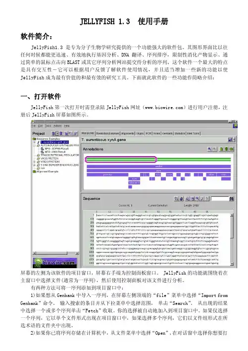
下面就此软件的一些功能作简略介绍:一、打开软件JellyFish第一次打开时需登录陆JellyFish网址()进行用户注册,注册后JellyFish屏幕如图所示。
屏幕的左侧为该软件的项目窗口,屏幕右手端为控制面板窗口。
JellyFish的功能就围绕着在主窗口中选择文件(通常为一序列),然后使用控制面板对该文件进行分析。
有两种方法可将一序列添加到项目窗口中:1)如果想从Genbank中导入一序列,在屏幕左侧顶端的“file”菜单中选择“Import from Genbank”命令。
输入搜索的条目并从下拉菜单中选择范围, 单击“Search”。
从出现的结果中选择一个或多个序列单击“Fetch”收取。
你的选择被自动地加入到项目窗口中。
如果仅选择一个序列,它以单个文件形式出现在项目窗口中,如果选择多个序列,它们以文件组形式在所选术语的文件夹中出现。
2)如果你已将序列存储在计算机中,从文件菜单中选择“Open”,在对话窗中选择你想要打开的文件,序列自动出现在项目窗口中。
当你关闭JellyFish时,你已建立的所有文件自动地存储在项目窗口中。
它们将在下一次打开JellyFish时出现在项目窗口中。
二、项目窗口项目窗口用于对序列进行组织排列。
当你在项目窗口中选择某一序列时,序列就在控制面板中被激活。
序列文件每一序列都有其自己的文件。
所有与序列有关的寡核苷酸和网络检索工具被储存在项目窗口中序列所在的文件夹中。
VYSIS说明书试验程序原理21 黄Y 黄X 绿在原位杂交X绿光探针centromerregion是一种在一个细胞标本里能看见特定的核酸序列(尤其是DNA)的技术,(FISH) 包括精确的单股荧光标记DNA探针的退火与目的基因互补. 探针荧光的DNA 位点能通过直接的检测用荧光显微镜看到。
羊水标本包括间期细胞用标准的细胞遗传学方法附着在玻片上。
样本标本DNA变性,然后与CEP x/y and LSI 21 探针杂交。
在杂交后,多余的和未结合的探针被一系列洗涤所除掉。
染色体和核DNA用特殊的染料被复染,复染剂DAP发蓝光.用装上适合的激动剂与发射滤器的荧光显微镜观察CEP X/Y 和LSI 21 DNA 探针杂交,能看到强烈的橘黄光和绿色的荧光信号和蓝色的复染核。
通过显微镜检查21 X, and Y染色体点计,荧光染色区域明亮地突出于核的DNA普通的蓝色荧光(通过DAPI复染) . FISH 程序能使核的21,X,and Y染色体点计可见。
CEP X/Y DNA 探针是一种绿光和橘黄光混合物,直接标记荧光的DNA探针,分别在X和Y染色体的DXZ1 和DYZ3 区。
LSI 21 DNA 探针是一种橘黄色光直接标记的荧光DNA 探针,包含特异性DNA 序列对应位于21号染色体21q22.13 到21q22.2 区的D21S259 和D21S342 基因座.所有探针混合物都在杂交缓冲液中经过了预变性以便于应用。
本试验设计目的是用荧光原位杂交法探测和量化21,X,and Y染色体。
试剂和仪器提供的材料本试剂盒包括四种试剂,够约20次测试。
储存和处理储存未开封的试剂盒做为一个整体在-20 ℃避光,避湿.20 x SSC 应单独储存于室温。
储存探针对照玻片在一个密封的容器中在-20℃,应用干燥剂防潮.每一个未开封的试剂盒成分的失效日期标于独立的标签上。
这些储存条件适用于所有开封及未开封的组成部分。
需要但未提供的材料实验室试剂超纯甲酰胺储存于+4℃至多一个月(从收到起,具体看制造商的建议的详细信息)浓缩盐酸(12N) HCL1N 氢氧化钠纯净水(蒸馏或去离子的or Milli-Q).储存于室温中carmoy’s 固定剂(3:1 甲醇:醋酸)drierite干燥剂1x 胰蛋白酶/EDTA(0.05% 胰蛋白酶,0.53Mm EDTA -4Na 于Hanks 平衡盐溶液中without Cacl2,Mgcl2.6H2O and M gSO4-7H2O)0.56%氯化钾实验室器械荧光显微镜(装备建议的滤光器)定相对照光学显微镜预先清洁的显微镜玻片玻片加温器(45 ℃-50 ℃)22mm x22mm玻璃盖玻片(1-10ul)微升消毒枪头聚丙烯微离心管(0.5ml or 1.5ml)定时器磁力搅拌器涡流微离心机量筒水浴(67±2℃和73±1℃)空气孵化器恒温箱(37℃)菱形头划线器湿室钳子(镊子)无菌注射器(5ml)Coplin 缸(6) 建议型号:wheaton 产品.No.900620 垂直染缸PH 计和PH 试纸校准的温度计金属试管架橡胶粘固剂0.45um 孔过滤器显微镜器材和滤光器显微镜:需要epi- 照明荧光显微镜观察荧光,应该检查以确定正确操作一台显微镜判断适合的普通DNA 染色,如DAPIpropidium lodide, and 阿的平可能不适合FISH ,应该常规显微镜清洁和制造商的技术顾问做定期的调整。

WelcomeThank you for making Fishman a part of your acoustic experience. We are proud to offer you the fi nest acoustic amplifi cation products available; high-quality professional-grade tools to empower you to sound your very best. We areconfi dent F1 Aura+ will both enhance and inspire your music making. Despite its simple and clean appearance, F1 Aura+ features a powerful set oftone shaping controls and programmability. We urge you to read through this user guide and spend some time getting familiar with its operation, so that you may easily realize the system’s full potential.Aura Acoustic Imaging Technology uses digital algorithms developed in Fishman’s audio laboratories to restore a studio-miked sound to an acoustic instrument. To achieve this, we’ve recorded this instrument using world-class microphones and techniques to capture an “Image” of the natural sound that it emits when miked in a professional studio. This Image, when recorded direct or played through an amp, mixer or PA, blends with the undersaddle pickup to produce an incredibly accurate recreation of the original recording.23Quick StartBefore you begin, set the controls as shown:1. Plug in • Use a ¼-inch instrument cable.2. T une up • Press and hold the Volume knob until the tuner comes on. When engaged, the Tuner mutes the output. Press Volume to exit Tuner.3. T urn up • Raise the Volume to a desirable level.4. Select an Image Preset • Press the Tone control repeatedly to select presets 1, 2 and 3. Press again to select the dry pickup (which is displayed as “P”).5. Adjust Tone • Turn the Tone control clockwise to blend in a “mid-scooped” tone with emphasized bass & treble and reduced midrange.4Performance ModeFor the more adventurous player, we’ve created a much deeper control interface called Performance mode. This mode gives you full access to an extensiveset of tone shaping controls. And to make things easier while you perform, we’ve grouped some controls into Play and the rest into Edit. Play and Edit are described on the following pages.Entering Performance ModeF1 Aura+ is shipped from the factory to power up in Easy Mode (page 6). To change the preamp to power-up into Performance Mode:1. Press + hold the Edit knob (Tone control) while plugging in the guitar. Continue to hold the Edit knob down when the tuner displays the letter “R” and then the letter “P”.2. While still holding the Edit knob, press the Volume knob. Release both knobs. Performance mode is selected when the “P” stops fl ashing and the unit returns to normal operation.8Play vs. EditPlayOnce in Performance Mode, plug in your instrument and it powers up into Play. In Play, Volume, Blend and Phase can be adjusted. The chromatic Tuner and the automatic Anti-Feedback circuit can also be activated. The Tone control is now referred to as the Edit knob.EditPress and release the Edit knob to enter Edit; the tuner’s green in-tune LED will light solid. Once in Edit, press the Edit knob repeatedly to step through the parameters. Each parameter is displayed using a single letter to represent its function (see page 19). Adjust its value by turning the Edit knob. A number is displayed and the tuner’s sharp/fl at lights show positive or negative values. Note: F1 Aura+ is programmable and automatically saves your settings.To exit Edit and return to Play, wait 15 seconds for the display to go dark, or press + hold the Edit knob for 2 seconds. You may also immediately exit by simultane-ously pressing both the Edit and Volume knobs.9Play Controls (cont.)BlendTurn Edit • Turn the Edit knob without pressing on it and the balance between pickup and Image is adjusted. A setting of P = 100% Pickup signal; 0 = a 50/50 pickup/Image blend; I = 100% Image signal.Suggestions• For live performance try backing off the Image by setting Blend to about 2 or 3 (about 65% pickup).• For recording, try blending in more Image for a realistic acoustic sound. Automatic Anti-FeedbackUse this search-and-destroy Anti-Feedback circuit in addition to Phase to control feedback during a performance. F1 Aura+ automatic Anti-Feedback circuit can apply up to three separate notch fi lters, which are very precise tone controls that reduce only a tiny piece of the audio band. When activated, the fi lter locates and reduces the problematic resonances associated with feedback.12While the Anti-Feedback control is very effective, it’s best if you spend some time while setting up before a performance and catch any issues before you begin to play. With some practice, you’ll fi nd you can also use it to “fi x” any resonant notes that may stand out in a particular venue.Using the automatic Anti-Feedback control:1. Press + hold both Edit and Volume for 2 seconds. The tuner display will fl asha “1” to indicate it is searching for the fi rst feedback.2. Turn up the Volume, then either dampen the strings while tapping the body or play the troublesome note until the feedback begins. The fi lter will automatically identify and eliminate the feedback. The “1” in the display will now light solid.3. At this point, you may continue to turn up your Volume as in step 2 to identify up to two more problematic resonances. Each is indicated via a fl ashing “2” or “3” during the search, in turn lighting solid when the resonance has beenidentifi ed.4. You may press the Volume knob at any time to cancel the search. The circuit will hold the notched frequenc(ies) in memory until the process is repeated.13Edit ControlsPress Edit knob to enter Edit; the tuner’s green in-tune LED will light solid. Once in Edit, press the Edit knob repeatedly to step through the parameters. Each parameter is displayed using a single letter to represent its function. Adjust its value by turning the Edit knob. A number is displayed and the tuner’s sharp/fl at LEDs indicate positive/negative values.Note: F1 Aura+ is programmable and automatically saves your settings.To exit Edit, wait 15 seconds for the display to go dark, or press + hold the Edit knob for 2 seconds. You may also immediately exit by simultaneously pressing both the Edit and Volume knobs.14Edit Controls (cont.)Image SelectF1 Aura+ is factory loaded with Images created especially for this instrument. Each Image corresponds to a different microphone type and position. Contact the guitar’s manufacturer to identify the microphone associated with each Image. Pickup EQBass, Mid and Treble controls allow you to fi ne tune the pickup signal. The pickup tone controls are designated by the capital letters T, M, B, corresponding to Treble, Mid, and Bass respectively.BlendBlend adjusts the balance between the pickup and Image and is representedby the letter X. A setting of P = 100% Pickup signal; 0 = a 50/50 pickup/Image blend; I = 100% Image signal.16CompressorThe Compressor (C) parameter adjusts several settings within a sophisticated automatic leveling circuit. As you increase the value, your overall playing dynamics become increasingly limited, making softer notes louder while controlling loud spikes in your playing. This can be helpful in performances where you desire a more even level to your playing. At its maximum setting, there may be some overall increase in the output level.Anti-FeedbackThis parameter, indicated with the letter A, allows you to temporarily disable the automatic Anti-Feedback fi lter if desired. O = Off, I = On. See page 12 for details on how to use the Anti-Feedback circuit.17Edit Controls (cont.)Image EQYou can program unique EQ settings for each of the Images. Unlike other Edit parameters, unique tone settings are automatically saved with each Image and recalled when an Image is selected. In order to prevent dramatic or unwanted changes, the Image EQ’s Treble, Mid, and Bass controls are separated from the Pickup EQ and located “under” the Volume knob in Edit. They are identifi ed by a lowercase t, m, b, corresponding to Treble, Mid, and Bass respectively.To EQ an Image:1. Adjust the Blend control so that you are hearing 100% Image (page 12)2. Press Edit knob to enter Edit and select an Image3. Press the Volume button to select the Image Treble EQ (t)4. Turn the Edit knob to boost or cut the Image Treble EQ5. Repeat steps 3 & 4 to adjust the Image Mid (m) and Image Bass (b)18PowerPlug in the guitar, and F1 Aura+ switches on. To conserve the battery, remove the instrument cable from the guitar when the system is not in use.The tuner display will fl ash at power-up to tell you the preamp is on.Low Battery IndicatorWhen the tuner fl ashes “L” once every three seconds, you have approximately 1.5 hours before the battery is exhausted. Change it at the next opportunity.20Restoring Easy ModeThere may be times when you want to return F1 Aura+ to Easy mode without losing your Performance mode settings. To do this:1. Press + hold the Edit knob while plugging in the guitar. Continue to hold the Edit knob down when the tuner displays the letter “R” and then the letter “I”.2. While still holding the Edit knob, press the Volume knob. Release both knobs. Easy mode is selected when the “I” stops fl ashing and the unit returns to normal operation.21Restore Factory Defaults1. Press + hold the Edit knob while plugging in the guitar. Continue to hold the Edit knob down when the tuner displays the letter “R”.2. Continue to hold the Edit knob, then press the Volume knob. Release both knobs. Factory reset is complete when the “R” stops fl ashing and the unit returns to normal operation.Defaults:• EQ for all Images reverts to fl at• Pickup EQ reverts to fl at• Blend is set to 50/50• Compressor is set to minimum• Anti-Feedback frequency is reset to 100Hz• Image selector reverts to Image #122Electrical Specifi cationsDigital Signal Path:A/D, D/A conversion: 24-bitSignal Processing: 32-bitTypical in-use current consumption @ 9VDC: 18mATypical 9V lithium battery life: 54 hours Typical 9V alkaline battery life: 27 hours Nominal output impedance: 1k Ohm Recommended load impedance: 10k Ohm and up Maximum output level (onset of clipping): +5dBVBaseline noise: -92dBV Dynamic Range: 97dBBass control: ±12dB @ 70Hz Midrange control: ±12dB @ 1kHz Treble control: ±***********All specifi cations subject to change without notice.23。


食品说明书翻译【篇一:说明书的翻译】商品说明书的翻译译文:德立邦——立鲜蔬果残留清除剂产品特点富含用高科技手段从椰果中提取的椰油两性醋酸(nacocoyl)特效成分,能快速溶解农药中的乳油成分,使农药合蔬果迅速剥离。
富含imazlil特效杀菌消毒成分,快速杀灭致病菌。
杀菌率99。
9%,持久保持蔬果新鲜美味。
本品所含活性成分经世界卫生组织、欧盟和美国环保署批准,符合联合国粮农组织标准,含有可食用标准成分。
本品为低泡型。
使用方法清洗蔬菜瓜果时,每公升水加入本品数滴,浸泡5分钟后,用清水冲洗即可实用。
注意事项本品位非饮品,请避免儿童触及。
不慎误食时,需多饮水。
(一)被动语态的使用商品说明数中被动语态的出现频率很高,这是因为商品说明书着重于可观描述;如对商品的操作过程、使用(食用)方法等描述,并没有必要说出动作的发出者。
(二)祈使句的反复使用常见英文说明书句型主要有以下几种: 1.(情态动词)be+形容词(或过去分词)+目的状语ginkgo biloba extract (gbe) has been shown to improve blood flow through both major blood vessels and capillaries.银杏叶片已证明能活血化淤通脉疏络。
(海王制药银杏叶片)this product can be used in hot water or steam line with the temperature limited to 225℃. 该产品用于温度225℃以下的热水管或蒸汽管道上。
2.分词(介词)+名词(非谓语动词形式增多)。
observe sterile technique at regular intervals when using this product. 使用本产品时需要定期注意遵守消毒规定。
exercise care during device handling to reduce the possibility of accidental device breakage. 处理装置时须特别小心,防止意外破损。

ASSEMBLY MANUALCopyright © 2015 Gorilla PlaysetsAll Rights ReservedLatest Revision: July 2, 2015Gorilla Playsets • 190 Etowah Industrial Court Canton, GA 30114See SawTABLE OF CONTENTSWarranty, Safety Guidelines and General Information.............…….......……...Pages 3 - 7 Kit Contents and Tool List…………..………………………………………....... Pages 8 - 10 Steps 1-6 .................................................................................................... Pages 11 - 16 Customer Registration Card……………………….....…..…………..….…………... Page 17PLEASE READ OWNER’S MANUAL CAREFULLYBEFORE STARTING ASSEMBLY!IMPORTANT – PLEASE READAs fresh lumber acclimates to its new environment, the natural tendencies of the tree can show itself in the form of checks, or “cracks” in the lumber. In almost all cases this is normal and it will not affect the structural integrity of your See Saw.Cosmetic defects that do not affect the structural integrity of the product, or natural defects of wood such as warping, checking or any other physical properties of wood that do not present a safety hazard, are not covered by this warranty. Defects that develop because the product is exposed to extreme climate conditions are not covered by this warranty. Defects that develop as a result of faulty or improper installation of the product are also not covered by this warranty.Most cracks are not warrantable, however if you believe that the integrity of yourplay set is compromised by this natural occurrence, please follow the warranty claim procedure found at . Click on the “Customer Care” tab on the left hand side of the page, then click on “Warranty Claim” and follow the instructions. We appreciate your purchase and know that you will enjoy your See Saw for many years to come.IF YOU HAVE MISSING OR DAMAGED PARTS OR NEED ASSISTANCE ASSEMBLING, PLEASE CALL Gorilla Playsets TM MANUFACTURING DIRECT. (800) 882-0272 FACTORY HOURS – MON.–FRI., 8AM-5PM EST DO NOT RETURN THIS PRODUCT TO THE RETAILER OR CONTACT THE RETAILER DIRECT.THE RETAILER DOES NOT STOCK COMPONENTS. PLEASE RETAIN THESE INSTRUCTIONS FOR FUTURE REFERENCE. KEEP THEM IN A SAFE PLACE WHERE YOU CAN REFER TO THEM AS NEEDED.CONTACT INFO:Gorilla Playsets190 Etowah Industrial CourtCanton, GA 30114Tel. (800) 882-0272Fax. (678) 880-3329***************************Check for revised instructions at /category-s/92.htmThank you for choosing Gorilla Playsets®We’ve included everything you need, except tools, to build your very own professional looking See Saw. When complete, your new See Saw should far exceed the quality of See Saw kits from other build-your-own companies. Our engineers and design team have over 30 years of playground experience. What we’ve developed is a product that doesn’t compromise quality for simplicity. Yet you’ll appreciate how quick and easy construction really is! Our See Saw kits are designed for children ages 3 to 11. Gorilla Playsets® believes every child should have a See Saw and with our kits they can! You can rest assured your new See Saw is safe, durable and designed to hold up to the elements. As parents ourselves, we know how important the security and well-being of our children is, and this shows in all of our products.Each See Saw features our step-by-step 3D illustrated manual, powder coated components, plus all the required hardware and pre-milled lumber.Quality LumberAt Gorilla Playsets, we use only the finest, hand selected lumber available. You can be assured that our lumber is strong, durable, and conforms to the national standards for use in children’s play equipment. It’s this quality that allows us to offer a 1 year warranty on the lumber used in our See Saw.Limited Manufacturers WarrantyGorilla Playsets® (“Gorilla”) warrants its See Saw to be free from defects in workmanship and materials, under normal use and conditions at its original installation, for one year for structural wood components and for one year for all other components (e.g., hardware, plastics, tarps, rope ladder, etc.)Cosmetic defects or natural defects of wood (e.g., warping, seasonal checking or cracking, knots, or knot holes, etc.) that do not affect the structural integrity of the product are not covered by this warranty. Defects that develop because the product is exposed to extreme climate conditions, or that develop as a result of faulty or improper installation of the product, are not covered by this warranty. Fading or discoloration of any part or accessory, cracks in plastic components, surface rust on hardware, and chips on powder coated materials are not considered defects in material as long as they do not affect the functionality or structural integrity of the part or component.It is the owner’s responsibility to properly maintain the product. Instructions for proper maintenance can be found on Gorilla’s website. Imperfections or defects that develop because of a failure to properly maintain the product are not covered by this warranty. Gorilla will repair or, at its discretion, replace any part within the stated warranty period that is defective in workmanship or materials. This decision is subject to verificationof the defect, which, at Gorilla’s discretion, may be accomplished by submitting photographs or by delivery of the defective part to Gorilla. Any warranty claim must include proof of purchase, including the date of purchase.This warranty is valid only if the product is used for the purpose for which it was designed and installed at a residential, single-family dwelling. This warranty is void if the product is put to commercial or institutional use. This warranty does not cover (a) products that have been damaged by acts of God, negligence, misuse, or accident, or that have been modified or repaired by unauthorized persons; (b) the cost of labor; or (c) the cost of shipping the product, any part, or any replacement product or part. GORILLA DISCLAIMS ALL OTHER REPRESENTATIONS AND WARRANTIES OF ANY KIND, EXPRESSED, IMPLIED, STATUTORY, OR OTHERWISE, INCLUDING THE IMPLIED WARRANTIES OF MERCHANTABILITY AND FITNESS FOR A PARTICULAR PURPOSE. GORILLA WILL NOT BE LIABLE FOR ANY INCIDENTAL OR CONSEQUENTIAL DAMAGES. This warranty is valid only in the United Statesof America, is nontransferable and does not extend to the owners of the product subsequent to the original purchaser, and only applies to the product as originally installed (in other words, installing the product and then later disassembling and reinstalling the product at the same or another location voids the warranty). Some states do not allow limitations on implied warranties or exclusion of incidental or consequential damages, so these restrictions may not be applicable to you. This warranty gives you specific legal rights. You may also have other rights which vary from state to state.IMPORTANT SAFETY GUIDELINESThis product is intended for residential use only and not intended for use in any public setting. A safety surface such as mulch or recycled tires should be used under the See Saw to prevent injury from falls. Also a 6 foot safety zone should be used around the entire See Saw.As with any home project, good judgment and respect for power tools will greatly reduce the risk of injury. Gorilla recommends you follow all tool manufacturers’ safety guidelines. Always wear eye protection and safety gloves to prevent injury. In several phases of construction two people may be required for lifting and securing of lumber. While the See Saw is being constructed, please keep children off the See Saw until the project is complete. Bolts and screw heads should be checked regularly for tightness. Gorilla shall not be liable for incidental, indirect or consequential damages or injuries that result from the building and/or playing on our See Saw. Adult supervision is recommended anytime the See Saw is being used.Weight Limit See Saw: 300 lbs TotalGeneral Info to Review Before Installation • Depending on your experience, assembly of the See Saw can take as little as 1 hour up to 2 hours.• Identify all of the parts for your See Saw. Empty the box and lay out boards so you can see each part. Your instruction book will have detailed drawings that will make it easy for you to recognize individual parts. Keep all hardware and metal parts separate from wooden pieces.• After everything is laid out, check carefully to ensure all parts are present. Make sure there are no broken boards.• Find an area to sort your hardware. It is best to open the hardware on a solid surface so that you do not lose any pieces in the grass. This will save time and familiarize you with all the different pieces in the hardware bag.• Important note: Wood has some natural defects such as knots, surface cracks, etc… We reject parts that are structurally defective. We use a high quality lumber in our structures; however, you should inspect each part for splinters or rough spots and sand them smooth to prevent injury.• After familiarizing yourself with all of the components, read all instructions thoroughly. Reading instructions after you have studied the parts will help you understand more clearly the installation process, and help to eliminate unnecessary mistakes.• Pay close attention to the diameter and length of each bolt and screw.• Never tighten hardware completely at first. It helps to have some adjustment for bolt alignment while you are attaching parts together. After everything is square, tighten each joint.• After you complete installation, make sure every bolt, screw, and nut is tight, and every board is secure. Wood will expand and contract with the seasons.• Check all bolt connections every season.• Place the See Saw on level ground, not less than 6ft from any structure or obstruction such as a fence, garage, house, overhanging branches, laundry lines, or electrical wires.READ! VERY IMPORTANT!If you are missing parts or have questions regarding the installation of our quality product PLEASE call us directly at the factory (1-800-882-0272). Our trained staff will behappy to assist you.Customer service hours:Monday thru Friday 8AM – 5PM ESTE-mail:***************************REQUIRED TOOL LIST:___ Standard or Cordless Drill w/ Phillips Bit___ 1/8” Drill Bit___ 9/16” Wrench and Socket___ 9/16” Deep Well Socket___ Tape Measure___ Extension Cord (if using standard drill)___ Hammer___ PencilHardware:see following pagesWood Components:see following pagesC ounter-sunk Holes - Many of the parts that will be used have counter-sunk holes. A counter-sunk hole is one that surrounds one side of a thru hole, but does not extend through the wood itself. When using a counter-sunk hole the bolt will be inserted through the thru hole. In some cases the bolt head with a washer will occupy the counter-sunk hole. In other cases a nut with a washer will occupy the counter-sunk g Screws - Lag screws are used in the construction of the See Saw. There will not be predrilled holes in the parts for the lag screw installation. Lag screws are self-tapping, though if you are using a manual socket wrench it may be necessary to tap the head of the lag screw with a hammer. You should also be sure to tighten the lag screws completely. Power tools such as an impact wrench or power drill should have enough torque to drive the lag screws without using a hammer, but make sure not to over tighten as this can cause the threads to “strip out” in the part.READ! VERY IMPORTANT!If you are missing parts or have questions regarding the installation of our quality product PLEASE call us directly at the factory (1-800-882-0272). Our trained staff willbe happy to assist you.Customer service hours:Monday thru Friday 8AM – 5PM EST E-mail:***************************Counter-sunk HoleThru Hole3/8 x 3-1/2”Lag Screw16 3/8 x 5”Lag Screw12 3/8 x 10” Carriage Bolt1 3/8” Washer Torque Washer2913/8” Lock Nut3/8” GreenBolt Cap11#10 x 2”Self TappingScrew41-3/8” X 6”LPivot Pipe11-3/8” x 11-1/2”Handle Pipe21-3/8”Vinyl Cap44 X 6 X 96”Main Beam1 4 X 4 X 18-1/2”Frame Block (At Right) (One countersunk hole)4 X 4 X 18-1/2”Frame Block (At Left) (Two countersunk holes)114 X 4 X 13-3/4”Seat44 X 4 X 20-1/2”Leg42 X 6 X 23-1/2”Side Leg Support22 X 4 X 17-1/2”Lower Leg Support24 X 4 X 9-1/2” Handle Block2Step 1: Seats1: Lay the 4 x 6 x 96” Main Beam on the ground. (see bottom photo) Place the 4 x 4 x 13-3/4” Seats against the 4 x 6 x 96” Main Beam. The counter-sunk holes of the Seat pieces should face the outside and each piece should be flush to the end and top of the Main Beam. The countersunk hole that is 2” from the end of the Seat pieces should be on the RIGHT as shown.2: Fasten each Seat piece to the Main Beam using two 5” lag screws and two 3/8” washers.3: Flip the Main Beam over.4: Repeat steps 1-2 to complete installing the remaining Seat pieces.4 X 4 13-3/4”See Saw Seat5” Lag ScrewCountersunk hole that is 2” from end of theseat is on the RIGHT.4 X 4 13-3/4”See Saw Seat See Saw Seatis 2” from end of the seat is on the RIGHT.NOTE: Each Seat hastwo countersunk holes.The hole that is 2” from the end should be on theRIGHT.Step 2: Main Beam1: Place the 1-3/8” x 6”L Pipe through the 1-3/8” hole in the 4 x 6 x 96” Main Beam.2: Place the 4 x 4 x 18-1/2” Frame Blocks on either side of the Main Beam.3: Work the 1-3/8” holes on the Frame Blocks onto the pipe. These holes will at first appear too small for the Pipe. They are intentionally manufactured this way in order to provide a tight fit. (use a rubber mallet or a scrap piece of wood and a regular hammer to assist in securing the Frame Blocks onto the Pipe.)4: Fasten the Frame Blocks to the Main Beam using the 10” carriage bolt with a Torque Washer, and 3/8” lock nut with 3/8” washer. The lock nut and washer will be inside the 1-1/4” counter-sunk hole.5: Tighten the 3/8” lock nut just enough to allow the Main Beam to still pivot.6: Place a green Bolt Cap over the threads on the end of the Carriage Bolt.10” Carriage Boltrounded over.Counter-sunk4 X 4 X 18-1/2” Frame Block with one sideCounter-sunkBolt CapStep 3: Legs And Leg Supports1: (See FIRST Below) Attach two 4 x 4 x 20-1/2” Legs to the 2 x 6 x 23-1/2” Side Leg Support. Align the top of the Side Leg Support with the bottom edge of the Counter-sunk hole in the leg. Make the end of the Side Leg Support flush with the face of the Leg.Attach the Side Leg Support to the Legs with four 3-1/2” lag screws and four 3/8” washers. Repeat this process to make another Leg/Leg Support assembly.2: (See SECOND Below) Place the Leg/Leg Support Assembly against the 4 x 4 x 18-1/2” Frame Block. Center the Leg/Leg Support with the Frame Block. Align the outside surface of each Leg with the bottom corners of the Frame Block.Attach the Leg/Leg Support Assembly to the Frame Block with two 5” lag screws and two 3/8” washers. Repeat this process for the other side.Side Leg Support4 x 4 x 20-1/2” See Saw LegsAlign Here FIRST:(Make two Leg Assemblies.)SECOND:(Attach Leg assemblies to Frame Blocks.)Align Bottom Corner ofFrame Block with surface of Leg on both sides.(Main Beam not shown for clarity.)Note:Counter-sunk holes in all parts should be facing you.Frame BlockStep 4: Lower Leg Supports1: Measure 2” from the bottom of each Leg and mark with a pencil.2: Place the bottom of the 2 x 4 x 17-1/2” Lower Leg Supports against the 2” mark.3: Fasten the Lower Leg Supports to the Legs using 3-1/2” lag screws and 3/8” washers.Lower Leg Support2”Step 5: Handle Assembly1: Place the 1-3/8” x 11-1/2” green Handle Bar through the 4 x 4 x 9-1/2” Handle Block.2: Make sure the weld seam inside the Handle Bar is on the bottom as shown in the picture.3: Place one end of the Handle Bar 4” away from the Handle Block.4: Use one predrilled hole as a guide to drill a 1/8” hole into the Handle Bar.5: Install a 2” self tapping screw into the 1/8” hole drilled in sub step 4.6: Use the other predrilled hole as a guide to drill a 1/8” hole into the Handle Bar.7: Install a 2” self tapping screw into the 1/8” hole drilled in sub step 6.8: Place a green 1-3/8” Cap onto each end of the Handle Bar.9: Repeat substeps 1 through 8 to assemble another Handle.1-3/8” x 11-1/2” Handle Bar4 x 4 x 9-1/2” Handle Block1-3/8” Cap#10 x 2” Self Tapping ScrewStep 6: Handles1: Place the Handle Block Assembly on top of the Main Beam, 7” from the Seats.2: Fasten the Handle Block Assembly to the Main Beam using 3-1/2” lag screws and 3/8” washers.3: Repeat substeps 1 and 2 for the other Handle Block Assembly.3-1/2”Lag ScrewHandle Block Assembly7”WARRANTY REGISTRATIONGorilla Playsets manufacturesthe finest quality products thatare designed for outstandingstrength and durability. Weback our products with anunparalleled warranty. In theunlikely event that you will needto contact us about coveredrepairs, we must have a validWarranty Registration on file.Where did you buy this product?:Place of PurchaseDate ofPurchaseName:Email:Address:Street City State ZipPlease selectyour age?18-3031-4041-5051+How old areyour children?2-34-56-78+How wouldyou rate thequality ofthis product?Would you recommend this product to friends & family?YesNoYour registration information:Comments:ExcellentAverageAbove AverageBelow AveragePoor- SEE SAW -。

非人造触手使用说明1非人造触手使用说明1尊敬的用户,感谢您购买我们的非人造触手产品。
本使用说明将为您提供关于产品的详细信息,以及正确的使用和保养方法。
请您仔细阅读本说明,以确保您能够充分享受我们产品带来的乐趣和便利。
1.产品概述非人造触手是一种仿生设计的装备,旨在模拟热带海洋生物的触手动作。
产品采用高品质的材料制成,结构坚固耐用,可以应对各种复杂的水下环境。
触手的伸缩长度和柔韧性可以根据用户的需要进行调整,以实现更好的操控效果。
2.使用前的准备在使用非人造触手之前,请确保以下准备工作已完成:2.1阅读说明书请仔细阅读本使用说明书,并了解产品的特点和功能。
确保您理解产品的操作方式和注意事项。
2.2适应环境2.3充电3.操作步骤3.1开关机触手的开关位于产品的底部或侧面。
长按开关按钮3秒钟,触手将开启/关闭。
开启后会有指示灯亮起,表示触手处于工作状态。
3.2伸缩控制触手的伸缩长度可以根据用户的需要进行调整。
在使用前,您可以通过按压按钮或滑动控制杆来调整长度。
请轻柔地操作,避免过度拉伸和损坏。
3.3运动控制触手的运动模式可以根据用户的需求进行选择。
触手通常具有上下、左右和旋转运动功能。
您可以通过轻触按钮或在操控器上滑动控制杆来实现运动控制。
3.4联机功能4.安全使用提示4.1使用人数为了确保使用的安全和舒适度,请确保每次使用触手的人数不超过所推荐的最大数量。
4.2使用时间建议每次使用触手的时间控制在30分钟以内,以免对手部肌肉造成过度疲劳。
4.3水下安全在使用非人造触手时,请遵循水下安全规则,确保自己和其他人的身体安全。
避免触碰锐利物品,以免损坏产品。
4.4儿童使用未成年人的使用必须在成人监护下进行。
请确保儿童使用触手时得到充分的指导和教育。
5.产品保养5.1清洁在使用触手之后,请用清水彻底清洁产品表面,并确保其干燥。
避免使用酒精、油脂和化学清洁剂,以免对产品造成损害。
5.2存储请将触手存放在干燥、阴凉的地方,避免阳光直射和高温环境。
股票代码:430601如有疑问欢迎垂询上海电话:************E-mail:**********************苏州电话:*************E-mail:************************ RNA FISH试剂盒(细胞爬片)说明书股票代码:430601一、检测原理RNA荧光原位杂交(Fluorescence in Situ Hybridization),简称为RNA FISH,是一种重要的非放射性原位杂交技术。
它的基本原理是:用已知的荧光染料标记单链核酸为探针,按照碱基互补配对原则,与待检测的RNA特异结合,二者经变性-退火-复性,即可形成靶RNA与核酸探针的杂交体,随后在荧光显微镜下对待测RNA进行相对定性、定量或定位分析。
二、组分和保存条件成分容量(50tests)容量(100tests)储存Buffer A(TritonX-100)30μL60μL室温Buffer C(20×SSC)6mL12mL室温Buffer E(杂交缓冲液)8mL16mL室温Buffer F(Tween20)50μL100μL室温DEPC水6mL12mL-20℃DAPI15μL30μL-20℃股票代码:430601三、试剂配置1.0.1%Buffer A配制:PBS999μL,Buffer A1μL,且每次新鲜配制;2.Buffer C母液为20×,用一级纯水稀释成4×、2×或1×使用;3.0.1%Buffer F配制:4×Buffer C999μL,Buffer F1μL,且每次新鲜配制;4.DAPI工作液:DAPI原液用PBS1000倍稀释,需避光保存和使用。
注意:1.探针应避光稀释并保存,且实验过程中加入探针后的操作应在避光条件下进行。
2.实验过程中常用试剂,如多聚甲醛等请您自备。
3.探针配制方法及保存请参考探针使用报告。
Introduction to jellyfishJellyfish (also known as jellies or sea jellies or Medusozoa) are free-swimming members of the phylum Cnidaria(刺胞动物). Jellyfish have several different morphologies that represent several different cnidarian classes including the Scyphozoa (over 200 species), Staurozoa (about 50 species), Cubozoa (about 20 species), and Hydrozoa (about 1000–1500 species that make jellyfish and many more that do not). Medusa is another word for jellyfish, and refers specifically to adult jellyfishJellyfish are found in every ocean, from thesurface to the deep sea. Some hydrozoan(水螅虫类的)jellyfish, or hydromedusae, are alsofound in fresh water; freshwater species are lessthan an inch (25 mm) in diameter, are colorlessand do not sting. Many of the best-knownjellyfish, such as Aurelia, are scyphomedusae(钵水母亚纲). These are the large, oftencolorful, jellyfish that are common in coastal zones worldwide.In its broadest sense, the term jellyfish also generally refers to members of the phylum Ctenophora(栉水母类). Although not closely related to cnidarian jellyfish, ctenophores are also free-swimming planktonic(浮游生物的)carnivores(食肉动物), are generally transparent(透明的)or translucent(半透明的), and exist in shallow to deep portions of all the world's oceans.Alternative names for groups of jellyfish are scyphomedusae, stauromedusae(十字水母目), cubomedusae(立方水母目), and hydromedusae(水螅水母纲). These may relate to an entire order or class.Culinary usesOnly scyphozoan(钵水母纲的) jellyfish belonging to the order Rhizostomeae(根口水母目)are harvested for food; about 12 of the approximately 85 species are harvested and sold on international markets. Most of the harvest takes place in southeast Asia. Rhizostomes, especially Rhopilema esculentum in China and Stomolophus meleagris (cannonball jellyfish) in the United States, are favored because of their larger and more rigid bodies and because their toxins are harmless to humans.Jellyfish strips in soysauce, sesame oil, andchili sauceTraditional processingmethods, carried out bya Jellyfish Master,involve a 20 to 40 daymulti-phase procedurein which after removingthe gonads and mucousmembranes, theumbrella and oral armsare treated with amixture of table salt andalum, and compressed.Processing reducesliquefaction, off-odorsand the growth ofspoilage organisms, and makes the jellyfish drier and more acidic, producing a "crunchy and crispy texture." Jellyfish prepared this way retain 7-10% of their original weight, and the processed product contains approximately 94% water and 6% protein. Freshly processed jellyfish has a white, creamy color and turns yellow or brown during prolonged storage.In China, processedjellyfish are desalted bysoaking in water overnightand eaten cooked or raw.The dish is often servedshredded with a dressing ofoil, soy sauce, vinegar andsugar, or as a salad withvegetables. In Japan, curedjellyfish are rinsed, cut intostrips and served withvinegar as an appetizer.Desalted, ready-to-eatproducts are also available. Fisheries have begun harvesting the American cannonball jellyfish, Stomolophus meleagris, along the southern Atlantic coast of the United States and in the Gulf of Mexico for export to Asia.。
Thank you for purchasing the Square Jellyfish Micro Ball Head. This product is designed for use with pocket cameras to add camera angle flexibility to a tripod.You will need two things:• A camera weighing up to 9 oz. with a tripod screw mount.• A tripod with a 1/4 x 20 standard camera thread screw. Alternatively, the Square Jellyfish Pocket Tripod may be also be used.Set up in two simple steps: • Gently thumb-tighten the screw of the Micro Ball Head onto the screw mount of your pocket camera.• Gently thumb-tighten the base of the Micro Ball Head onto thread screw of your tripod.Position your cameraOnce set-up is complete, you can then position your camerain a broad range or angles. The built-in tension of the Ball Head holds your camera firmly in place. If desired, a small screwdriver can be used to adjust the tension looser or tighter by slightly turning the recessed set-screw at the bottom of the Micro Ball Head.Use common sense• Do not place your camera where it can easily fall a distance that would cause damage to your camera.• This product contains small parts that may be a chocking hazard. Keep out of reach of children.Micro Ball Head shown withMicro Ball Head shown withSquare Jellyfish Pocket Tripod SqUare JellYfiSH Micro Ball Head USer’S ManUalSquare JellyfiSh Micro ball head ProducT warranTywarninGThe Micro Ball Head is designed for use with pocket cameras to add camera angle flexibility to a tripod. Be careful when positioning your camera so that it does not fall over. Y ou must take care to make sure that the camera remains balanced after it is aimed by making sure the thumb screws are tight enough. This device is designed to support lightweight, compact cameras up to 9 oz., and not heavy cameras, SLRs, or any camera with a lengthy lens or similar extension. Always support the camera with one hand while you are tightening it in place with the other hand. While still supporting it, wiggle the camera a bit to make sure that it will not tip over when you release it, because this might damage your camera! Only you can make a safe evaluation of whether your camera is secure and balanced because of the infinite number of settings which you may choose.liMiTed warranTyThe Micro Ball Head is warranted against defects in materials and workmanship for a period of ONE (1) YEAR from the date of the original retail purchase. If a defect exists the manufacturer will, at its option and to the extent permitted by law, (1) repair the product at no charge using new or refurbished parts; or (2) exchange the product with a functionally equivalent product that is new or refurbished; or (3) refundthe original purchase price. This warranty excludes damage resulting from abuse, accident, modifications or other causes that are not defects in the materials or workmanship. T o the extent permitted by applicable law, the manufacturer is not liable for any direct, indirect, incidental or consequential damage arising out of the use of service of the product, including, but not limited to damage which may be caused to any camera, or to any other device the Micro Ball Head is used to support. T o the extent permitted by applicable law the manufacturer of the Micro Ball Head disclaims all implied warranties of merchantability and fitness for a particular purpose. If implied warranties cannot be disclaimed, then such warranties are limited in duration to the duration of this warranty. This warranty gives you specific legal rights, and you may have other rights which vary from state to state.To obtain warranty service, contact Square Jellyfish using the information provided at To the extent permitted by applicable law proofof purchase for all warranty repairs/replacementis required.。
《典范英语》Jellyfish原文Jellyfish Shoes1Laura had some new jelly shoes. She was really proud of them. They were pink and see-through like raspberry jelly. She ran down to the beach in them. Wherever she walked, they left little tracks in the sand. Like this: 'Look, Scott,' Laura called to her brother. 'My new jelly shoes are leaving stars in the sand.' Squidge. Laura trod in something slippery. She lifted up her shoe. 'Ughhh!' she said.' What's that mess?' 'It's only a jellyfish,' said Scott.' The sea washes them up on the beach.' 'Well, I don't like it,' said Laura. 'It looks like a jelly cow-pat.' Slosh. The sea washed up some more jellyfish. Pink ones this time. They spread out in pink puddles on the sand. 'Watch out,' said Scott.' Jellyfish can give you a nasty sting.' 'Yuk! ' cried Laura. 'There are loads of them! And, phew, what a pong! I hate them. They'll spoil my new jelly shoes!' Scott looked at the jellyfish on the sand. He looked at Laura's new shoes. An idea popped into his head. 'I don't know why you hate jellyfish,' said Scott. 'What do you think your new shoes are made of?' Laura looked down at her shoes. They were see-through and pink. The jellyfish on the beach were see-through and pink too. 'Don't be silly,' she told Scott. But her voice was shaky.2'I thought you knew,' said Scott. 'Don't you know what happens to all these washed-up jellyfish?' Laura shook her head. 'I'll tell you what happens,' said Scott, who was good at stories. 'The jelly workers come round. They come round at night with bin bags. And they shovel all the jellyfish into the bags. And theytake them away to the Jelly Shoe Factory.' He went on, 'And they make them into shoes. Just like the ones you've got on. I thought everyone knew that!' Laura looked down at her new shoes. 'I don't think I like my new shoes any more,' she said. Then she tore them off. 'Yuk!' she said. 'I don't want pongy jellyfish shoes that sting me!' She threw them into the sea. They didn't sink. Jellyfish shoes don't sink. They just bobbed about on the waves. And washed further and further away from the shore. 'Good riddance!' shouted Laura, waving them goodbye. Then she tiptoed back to the house in her bare feet.3That night Laura dreamed about the jellyfish workers. She dreamed they crept along the beach with bin bags in their hands. They bent down and shoveled up jellyfish. Soon they had whole shivering sackfuls of them. Flies were buzzing all around them. 'Oh no!' cried Laura, waking up. 'The jelly workers are coming!' But it was all right. She was safe in her own bed. 'It was just a bad dream,' she told herself. Yet down on the dark beach, something was moving. Something was bobbing about on the waves. It was Laura's jellyfish shoes. They were coming back home. Gently, they washed in on the wave tops until at last a big wave tops until at last a big wave washed them up on the sand. Neatly side by side. 'What a bit of good luck!' said Mum the next morning. 'Guess what I just found on the beach?' Don't know,' said Laura. Mum held up the jellyfish shoes. 'These!I bet you didn't even know you'd lost them.' Mum tipped up one of the shoes. A winkle fell out of the toe. 'Here you are,' she said, handing the shoes to Laura. 'You can put them back on now.' Laura pushed the shoes away: 'I won't put them back on!' she shouted. 'You can't make me!' Mum stared at her. 'What on earthis the matter? I thought you'd be pleased to get them back.' 'I don't want them. I don't want smelly shoes that make flies buzz all around me! Why did you do it, Mum?' Why did you buy me shoes made of jellyfish?' And Laura rushed out of the door. Mum shook her head, puzzled. 'Shoes made of jellyfish?' she said. 'What's she talking about? Do you know, Scott?' 'Don't ask me,' said Scott. But he looked a bit guilty.4Laura rushed down to the beach without her jellyfish shoes. Scott came running after her. He had the shoes in his hand. 'Mum says you've got to put them on.' 'No! I'm never wearing those horrible shoes again! Not ever!' 'Look,' began Scott. 'There's something I've got to tell you. What I said yesterday, about the Jelly Shoe Factory-'But he didn't get time to finish. 'What's that?' said Laura. 'What's that in the sea?' The sea was full of tiny, frilly parachutes. They were pink and brown and purple. 'They're beautiful!' cried Laura. 'What are they?' 'They're baby jellyfish,' said Scott. 'Hundreds of them.' 'Jellyfish!' Laura jumped back. 'And if we don't save them,' said Scott, 'the sea will wash them up. They'll get splatted on the sand. They'll all die.' 'I hate jellyfish!' said Laura. 'They pong. They sting you. They get made into jellyfish shoes.' 'Well, I'm going to save them,' said Scott. And he raced back to the house. Laura couldn't help watching the jellyfish. They sparkled like jewels. But they were getting closer and closer to the beach. Soon they would be dried-up puddles on the sand. And she couldn't help thinking, 'Poor babies.' Just then, Scott came racing back with two buckets. And suddenly Laura changed her mind. 'I'll help you to save them,' said Laura. She grabbed a bucket. 'We'll tip them into that rock pool,' said Scott. 'But we've got to hurry!' 'Don't touch them,' he warned.'Even the babies sting.' They scooped up the babies in buckets. Then they ran to the rock pool and tipped them in. 'Hurry!' cried Scott. 'The sea's going out!'5Laura dashed to the rock pool. Slosh! The babies poured out like rainbows. She ran back again and again. Until her legs wouldn't work any more. 'I-can't-run-another-step!' she gasped, setting down on the sand. 'It's all right,' said Scott. 'Look! The tide's coming in!' Laura lifted her head. It was true! 'Hurray! She yelled. 'We've saved them. We saved the jellyfish babies!' Scott and Laura went to look in the rock pool. 'It's like jellyfish soup in there!' said Laura. 'But they're safe,' said Scott. 'And when the tide comes in, it'll take them out to the deep, deep sea-where they belong.' 'I like jellyfish now,' said Laura. 'They're beautiful, aren't they? I'm really glad we saved them. And now the jelly worker won't get them. They won't be taken to the Jelly Shoe Factory and made into jellyfish shoes.' Scott looked very guilty. 'I was going to tell you about that,' he said. 'There isn't any jelly shoe Factory. 'There isn't any jelly workers. They don't make jelly shoes out of washed-up jellyfish.' 'How do you know?' said Laura. 'Because it's just a story. I made it all up!' 'No you didn't !' said Laura. 'I did, I did, honest!' said Scott. But Laura didn't believe him. 'Where are my jellyfish shoes anyway?' she asked Scott. Scott looked around. 'I don't know. I put them down when I went to get the buckets. They can't have walked off by themselves…' Laura looked around too. The beach was empty. Then she saw a line of stars, in the sand. They led right down to the sea. 'There they are!' Scott pointed. Laura saw her jellyfish shoes. They were bobbing about on the waves. They were heading out to sea. Scott waded into the water. 'I'm going to get them back!' he said. Laura thoughtfor a minute. Then she said, 'No. Let them go.' She waved at them. 'Bye bye, jellyfish shoes,' she said, a little sadly. 'What are you going to tell Mum?' asked Scott. 'She'll be very angry!' But Laura wasn't listening. She was smiling a secret smile. She was thinking about her jellyfish shoes having a lovely time… swimming with whales and dolphins and octopuses… back in the deep, deep sea where they belonged.。
97803C (Rev. F - 3/05)Halsey Taylor Owners ManualIMPORTANT! INSTALLER PLEASE NOTE.THE GROUNDING OF ELECTRICAL EQUIPMENT SUCH AS TELEPHONE, COMPUTERS, ETC. TO WATER LINES IS A COMMON PROCEDURE. THIS GROUNDING MAY BE IN THE BUILDING OR MAY OCCUR AWAY FROM THE BUILDING . THIS GROUNDING CAN CAUSE ELECTRICAL FEEDBACK INTO A FOUNTAIN, CREATING AN ELECTROLYSIS WHICH CAUSES A METALLIC TASTE OR AN INCREASE IN THE METAL CONTENT OF THE WATER. THIS CONDITION IS AVOIDABLE BY USING THE PROPER MATERIALS AS INDICATED. ANY DRAIN FITTINGS PROVIDED BY THE INSTALLER SHOULD BE MADE OF PLASTIC TO ELECTRICALLY ISOLATE THE FOUNTAIN FROM THE BUILDING PLUMBING SYSTEM.IMPORTANTALL SERVICE TO BE PERFORMED BY AN AUTHORIZED SERVICE PERSONFIG. 2FIG. 1HCRF- EBPNOTE: WA TER FLOW DIRECTIONBUILDING WATER INLETSERVICE STOP (NOT FURNISHED)1/4" O.D. TUBE WA TER INLET TO COOLER3/8" O.D. UNPLATEDCOPPER TUBE CONNECT COLD WA TER SUPPLYNon-Refrigerated Fountain With Back Panel97803C (Rev. F - 3/05)PAGE 2L E G E N D A = R E C O M M E N D E D W A T E R S U P P L Y L O C A T I O N 3/8 O .D . U N P L A T E D C O P P E R T U B E C O N N E C T S T U B B E D 1-1/2" (38m m ) F R O M W A L L S H U T O F F B Y O T H E R S B = R E C O M M E N D E D L O C A T I O N F O R W A S T E O U T L E T 1-1/4" O .D . D R A I N C = 1-1/4" D R A I N F U R N I S H E DH C R F - E B P R O U G H -I NF I G. 3HCRF - EBP INSTALLATION INSTRUCTIONS1. Wall should already be framed for the fountain using the positioning dimensions shown in Figure 3. Showndimensions pertain to installation location (framing must support up to 300 lbs. weight). These dimensionsare required for compliance with ANSI Standard A117.0.2. Attach wall plate assembly to wall as shown in Figure 3 using 5/16" x 2" long bolts and flat washers(not provided). Tighten securely. (Fastener must match wall type, i.e. lag screws for wood studs, bolts andanchors for masonary construction.)3. Install back panel. Place the upper edge of the panel above hanger on the wall. Slide panel down until itengages the hanger. Be sure back panel is firmly engaged before releasing it.4. Install rough-in plumbing as shown in Figure 3. Waste line should extend a minimum of 2" (51mm) thru theback panel. Run supply water inlet line thru back panel. Install a service stop (not provided). Turn on supplywater and flush thoroughly.5. Remove bottom access panel from fountain basin and save the screws. Install the fountain to the backpanel using (4) 5/16" x 3/4" long screws and washers (provided) thru holes in back panel. Tighten securely.6. Cut waste tube to required length using plumbing hardware and a trap (not provided) as a guide. Installhardware and trap. Tighten securely.7. Make water supply connections from service stop to the 3/8" O.D. unplated copper tube coming out of thefountain strainer (See Fig. 1). Turn on water supply and check for leaks. Newly installed water supply lineshould be insulated after leak check is completed. DO NOT SOLDER TUBES INSERTED INTO THE STRAINERAS DAMAGE TO THE O-RINGS MAY RESULT.8. These products are designed to operate on 20-105 PSIG supply line pressure. If inlet pressure is above105 PSIG, a pressure regulator must be installed in the supply line. Any damage caused by reason ofconnecting these products to supply line pressure lower than 20 PSIG or higher than 105 PSIG is notcovered by warranty.9. Check stream height from bubbler. Stream height is factory set at 45-50 PSI. If supply pressure varies greatly from this, adjust the screw on regulator item 9 by using a small screwdriver through the small hole in thepush button item 3 (See Fig.5). Clockwise adjustment will raise stream height and counter-clockwiseadjustment will lower stream height. For best adjustment stream height should be approximately 1-1/2" (38mm) above the bubbler guard. (See Fig. 6)10. Replace bottom access panel to fountain basin using screws provided. Tighten securely.TROUBLE SHOOTING AND MAINTENANCE1. Orifice Assy: Mineral deposits on orifice can cause water flow to spurt or not regulate. Mineral depositsmay be removed from orifice with a small round file not over 1/8" diameter or a small diameter wire.CAUTION:DO NOT file or cut orifice materials.2. Stream Regulator: If orifice is clean, regulate flow as in "START UP" instructions above. If replacement isnecessary, see parts list for correct regulator part number.3. Actuation of Quick Connect Water Fittings: Cooler is provided with lead-free connectors which utilize ano-ring water seal. To remove tubing from the fitting, relieve water pressure, push in on the gray collar whilepulling on the tubing (See Figure 2). To insert tubing, push tube straight into the fitting until it reaches apositive stop, approximately 3/4".97803C (Rev. F - 3/05)PAGE 397803C (Rev. F - 3/05)PAGE 4P ART NO.ITEM NO.PARTS LISTStrainerRetaining Nut Push ButtonPush Button Sleeve Regulator Holder Bubbler Assy GasketBubbler - Nipple Regulator Cap ScrewScrew - #10-24 X .50 PHTC StrainerFountain Arm - LongBottom Cover Plate - Long Back Panel Hex NutRegulator Mounting Bracket Poly Tubing (Cut To Length)Mounting Plate Assy Drain - Tailpipe Drain - Adapter Gasket - Tail Pipe Tube - Water InNut-Regulator MountingWasher - Flat .339/.359ID Steel Screw - Mach. 5/16-18 x 3/440575C 15005C 45662C 45737C 50986C 51544C 10032274056015008C 61313C 75672C 11262754389055996C 550011305500066528290C 40045C 28291C 56092C 28286C 45679C 45805C 50074C 62095C 45736C 75541C 1115772438901234567891011121314151617181920212223242526DESCRIPTIONFIG. 7FIG. 616295341713SEE FIG. 615SEE FIG. 5141,20,21,2212FIG. 5181923678FIG. 42222 CAMDEN COURT OAK BROOK, IL 60523241125,2610。
PhilipsEntertainment Tablet8"8GBPI7100S2Live. Work. PlayPowered by Android™ 4.2 (JellyBean)Take Philips entertainment tablet wherever you go. Experience movies, music and web surfing like never before. This Google-certified Android 4.2 tablet delivers awesome video and audio, thanks to FullSound and vivid LCD display.Small yet versatile•Quad core 1.2GHz processor for fast & smooth user experience •Built-in GPS for navigation, social networking and gaming Surround yourself with non-stop entertainment •20cm (8”) TFT color LCD screen•4:3 screen provides big screen for reading and web surfing •Bluetooth stereo to enjoy wireless music •Fullsound to bring your Tablet music to lifeConnect to a world of endlessly entertaining apps•Google-certified & Android™4.2 platform for best web surfing •Access to thousands of apps and games via the Hi-Market •High-speed Wi-Fi for fast internet access and app downloadHighlightsFullsound™ - TabletPhilips' innovative FullSound technologyfaithfully restores sonic details to compressed MP3 music, dramatically enriching and enhancing it, so you can experience truly immersive music without any distortion. Based on an audio post-processing algorithm, FullSound combines Philips' renowned expertise in music reproduction with the power of the latest generation Digital Signal Processor. The result is fuller bass with more depth & impact, boosted voice and instrument clarity, and rich detail. Rediscover yourcompressed MP3 music in true-to-life sound that will touch your soul & move your feet.Hi-Market Enjoy great applications from the Hi-Market. Just click on the icon on your Philipsentertainment tablet to connect to the Hi-Market via Wi-Fi, and start your search for apps. Download games, tools and e-books, or apps to personalize your entertainment tablet – for free or for a small sum. The clear, easy-to-use interface lets you browse intuitively through applications which can be sorted according to rating, category or popularity. Download apps directly to your tablet and enjoy them instantly.High-speed Wi-FiHigh-speed Wi-Fi for fast internet access and app download20cm (8”) TFT color LCDThe high resolution color LCD display brings images to life, showing off your treasured photos, favorite movies and music with the same 'real life' rich detail and vibrant colors as high quality prints.4:3 screen4:3 aspect ratio is closer than 16:9 to what the human eye is used to reading. When the screen is held vertically, it matches up to real books. Furthermore, for web surfing, the text will look bigger when compared to an identically-sized 16:9 screen.Bluetooth stereo musicYour tablet supports Bluetooth stereo music streaming. It lets you enjoy your favorite tunes in high quality stereo music wirelessly from your tablet via Bluetooth stereo headphone/ headset.Built-in GPS for navigationBuilt-in GPS for navigation, social networkingand gamingIssue date 2017-04-04 Version: 1.0.312 NC: 8670 001 09307 EAN: 69 23410 72503 2© 2017 Koninklijke Philips N.V.All Rights reserved.Specifications are subject to change without notice. Trademarks are the property of Koninklijke Philips N.V. or their respective owners.SpecificationsPicture/Display•Diagonal screen size: 8 inch / 20.3 cm •Resolution: 1024(w)x768(h)x3(RGB)•Display screen type: IPS LCD display•Display colors: 16 millions•Aspect ratio: 4:3•Multi-touch capacitive panel: 5 points •BacklightSound•Built-in speakers: Yes, Mono•Output Power: 0.7W•Frequency response: 250 - 15kHz (For speaker)•Signal to noise ratio: > 70 dB(A)•THD: 1% at 1kHz•Sound Enhancement: FullSound2•Sound personalizationVideo Playback•H.263: 3GPP container•MPEG4 SP/ASP: Up to D1 (720x480) resolution, 30fps, bit rates up to 4Mbps in .avi and .mp4 container•MPEG4/ H.264 HP: Up to D1 (720x480) resolution, 30fps, bit rates up to 4Mbps in .avi and .mp4 containerAudio Playback•MP3 bit rates: 8 - 320 kbps and VBR •Compression format: MP3, 3GPP, AAC, AMR-NB, AMR-WB, FLAC, MIDI, Ogg Vorbis, WAV•ID3 Tag support: Track title and artist name •MP3 sample rates: 8, 11.025, 16, 22.050, 24, 32, 44.1, 48 kHzCameras•Front facing camera: 2 MP•Rear camera: 5MP, AutofocusConnectivity•Wireless LAN: 802.11 b/g/n•SD/MMC card slot: Micro SD card slot (Support up to 32GB)•USB: High speed micro USB•Headphone jack: 3.5mm Stereo Headphone•3G data connectivity: WCDMA 900/2100 HSDPA •Bluetooth•Bluetooth profiles: A2DP, AVRCP, File transfer profile•Bluetooth version: 3.0•Built-in GPS•FM RadioConvenience•Battery charging indication: On user interface •Battery low indication•Dedicated volume controls•Firmware upgradeable•G-sensor•Superscroll•Screen lockAccessories•AC/DC Adaptor: Input: AC 100-240V/0.5A,Output: DC 5V/2A•Quick start guide•USB cable: Yes, USB-Micro USB cablePower•Battery Type: Built-in battery, LI-Polymer•Battery lifetime: Up to 3hrs video playback (WiFioff)•Battery capacity: 4800mAh•Rechargeable: Yes, via USBDimensions•Master carton dimensions: 207 x 47 x 132 mm•Master carton quantity: 5•Master carton weight: 2.02 kg•Product dimensions (W x H x D):196.5 x 122.6 x 9.9 mm•Product weight: 0.285 kg•Packaging type: D-box•Packaging dimensions (WxHxD): W207 x D132 xH47 mmAudio Capturing•Built-in microphone: mono•Voice recording: Yes, AMR•Audio file format: AMRGreen Specifications•Lead-free soldered productOperating System•Android 4.2 (Jelly Bean)Still Picture Playback•Picture Compression Format: BMP, GIF, JPEG,PNG•Slide showStorage Media•Built-in memory (RAM): 1GB RAM/8GB Flash•Built-in memory type: NAND FlashSystem Requirements•Internet connection: Yes (For software upgradeand access to support document)•PC OS: Windows XP (SP3)/ Vista/ 7•Free USB port•Windows Media Player: 11 or abovePreloaded Applications•HiMarket•Sina MicroBlog•Sina News•Web Browser•360Buy•Baidu Input•Duomi Music•ES File explorer•Panda Reader•QQ Games•DockStudioOuter Carton•Gross weight:4.3 kg•GTIN: 1 69 23410 72503 9•Outer carton(L x W x H): 26 x 18.5 x 24.5 cm•Nett weight: 2.7 kg•Number of consumer packagings: 5•Tare weight: 1.6 kgPackaging dimensions•Packaging dimensions (W x H x D):22.5 x 4.8 x 16.8 cm•EAN: 69 23410 72503 2•Gross weight: 0.81 kg•Nett weight: 0.54 kg•Number of products included: 1•Packaging type: Display•Tare weight: 0.27 kg•Type of shelf placement: LayingProduct dimensions•Product dimensions (W x H x D):20.6 x 1 x 15 cm•Weight: 0.451 kg*Rechargeable batteries have a limited number of charge cycles andmay eventually need to be replaced. Battery life and number ofcharge cycles vary by use and settings.*Battery life varies by use and settings.*Battery life of playtime is approximate and may vary depending onapplication condition. To optimize battery life, user should turn LCDbacklight to minimum, connect to headphones (not built-in speakers)and listen at medium volume level, and use the product at roomtemperature.。