RTX51多任务操作系统中文使用指南
- 格式:pdf
- 大小:300.92 KB
- 文档页数:43
![RTX51小型实时操作系统介绍[1]](https://uimg.taocdn.com/0a15223e87c24028915fc390.webp)
RTX51小型实时操作系统介绍(连载1)有二个不同的RTX51版本可以使用∶RTX51 Full使用多于四个任务优先权同时完成存在时间片轮转调度和抢先式的任务切换。
RTX51工作在与中断功能类似的状态下。
信号和消息可以通过邮箱系统在任务之间互相传递。
你可以从一个可分配存储区中分配和释放内存。
你可以强迫一个任务等待中断、超时或者是从另一个任务或中断发出的信号或消息。
RTX51 Tiny 是 RTX51的一个子集,它可以很容易地在没有任何外部存储器的单片8051系统上运行。
除了下列例外,RTX51 Tiny支持许多 RTX51中的特性。
RTX51 Tiny仅支持时间片轮转任务切换和使用信号进行任务切换。
不支持抢先式的任务切换。
不包括消息历程。
没有可分配存储区分配程序。
许多微处理器应用程序要求同时执行两个工作或任务。
对于这样的应用程序,一个实时操作系统(RTOS)允许灵活的分配系统资源(中央处理器、存储器、等等.)给各个任务。
RTX51是一个很容易使用的功能强大的实时操作系统。
R TX51可以运行于所有的 8051 派生机型。
你可以使用标准 C语言编写和编译一个程序并使用 C51 构造、编译他们,仅在指定任务标识符和优先权上有一点差别。
. RTX51程序也要求你在程序中用include命令引入实时管理的头文件并使用 BL51 linker/locator进行连接和选择适当的 RTX51库文件。
RTX51小型实时操作系统介绍(连载2)单任务程序一个标准的 C语言程序从主函数开始执行。
在一个嵌入式应用中,主函数通常是一段无限循环的代码,可以认为是一个连续执行的单独任务。
时间片轮转程序一种更高级的 C语言程序可以在不使用实时操作系统的情况下实现时间片轮转拟多任务系统。
在这种系统中、任务或功能被一段无限循环程序重复调用。
例如∶用 RTX51进行时间片轮转调度rtx51也能完成多重任务时间片轮转,而且允许准并行执行多个无限循环或任务。
目录总览 (2)实时程序 (5)操作原理 (7)配置RTX51 Tiny (11)使用RTX51 Tiny (14)实例 (17)函数参考 (18)总览RTX51 Tiny是一个实时系统,它允许你创建可同时执行多个功能或任务的应用程序。
在嵌入式应用中这往往是必须的。
虽然可以创建无RTOS实时程序(通过执行一个或多个任务循环),但诸如调度,维护和时序问题,像RTX51 Tiny这样的RTOS可以解决。
一个实时的操作系统可以灵活的调度系统资源,像CPU、内存和任务之间的通信。
RTX51 Tiny是一个功能强大且简单易用的RTOS,适用于所有8051衍生产品。
在Keil C51编译器中RTX51 Tiny是用标准C(ANSI C)编写的。
C语言允许你轻松的定义任务功能而不必进行复杂的栈和变量设置。
RTX51程序需要包含一个特殊的头文件且链接RTX51库到程序中。
1.新特性RTX51 Tiny第二版包含了许多新特性使实时软件开发更容易,如下代码分段RTX51 Tiny现在支持代码分段(需配置文件L51_BANK.A51文件)。
明确任务切换新功能(OS_SWITCH_TASK)可以是一个任务处于就绪状态并立即切换至另一个任务。
任务就绪标志新的RTX51 Tiny库允许给任务设置就绪状态标志,使任务处于就绪状态,在一个时间间隔、超时或接受到信号后恢复运行。
CPU空闲模式RTX51 Tiny允许CPU处于空闲模式定时器中断的用户代码支持开发者可以添加自己的代码到RTX51 Tiny定时器中断中,也可以为自己的例程设置和RTX51 Tiny相同的例程(需配置CONF_TNY.A51)。
支持间隔时间设置OS_REST+INTERVAL允许开发者在混合的时间间隔和信号中调用OS_WAIT来调整超时时间。
此外,RTX51 Tiny已被重新组合以具备灵活性、加速性以及对代码和数据空间要求更小。
RTX51 Tiny第二版在显著减小代码量并具有可扩展性。

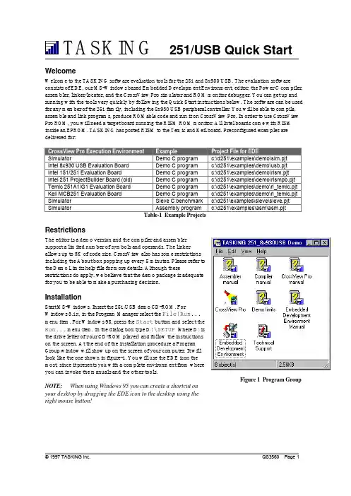
WelcomeWelcome to the TASKING software evaluation tools for the 251 and 8x930 USB. The evaluation softwareconsists of EDE, our MS-Windows based Embedded Development Environment, editor, the Power C compiler,assembler, linker/locator, and the CrossView Pro simulator and ROM monitor debugger. You can get up and running with the tools very quickly by following the Quick Start instructions below. The software can be used for any member of the 251 family, including the 8x930 USB peripheral controller. You will be able to compile,assemble and link programs, produce ROMable code and run it on CrossView Pro. In order to use CrossView Pro ROM, you will need a target board running the RISM ROM monitor. All Intel boards come with RISM inside an EPROM. TASKING has ported RISM to the Temic and Keil board. Preconfigured examples are delivered for:SimulatorDemo C programc:\d251\examples\demo\sim.pjt Intel 8x930 USB Evaluation BoardDemo C program c:\d251\examples\demo\usb.pjt Intel 151/251 Evaluation BoardDemo C program c:\d251\examples\demo\rism.pjt Intel 251 ProjectBuilder Board (old)Demo C program c:\d251\examples\demo\rismpb.pjt Temic 251A1/G1 Evaluation BoardDemo C program c:\d251\examples\demo\ri_temic.pjt Keil MCB251 Evaluation BoardDemo C program c:\d251\examples\demo\ri_temic.pjt SimulatorSieve C benchmark c:\d251\examples\sieve\sieve.pjt Simulator Assembly program c:\d251\examples\asm\asm.pjtTable-1 Example ProjectsRestrictionsThe editor is a demo version and the compiler and assemblersupport a limited number of symbols and operands. The linkerallows up to 3K of code size. CrossView also has some restrictionsincluding the About box popping up every 5 minutes. Please refer tothe Demo Limits help file for more details. Although theserestrictions do apply, we believe that the demo package is adequatefor you to be able to make a purchasing decision.InstallationStart MS-Windows. Insert the 251/USB demo CD-ROM. ForWindows 3.1x, in the Program Manager select the File|Run...menu item. For Windows 95, press the Start button and select theRun... menu item. In the dialog box type D :\SETUP (where D: isthe drive letter of your CD-ROM player) and follow the instructionson the screen. At the end of the installation procedure a ProgramGroup window will show up on the screen of your computer. It willlook like the one shown in figure-1. You will use the EDE icon themost, since it presents you with a complete environment from whereyou can invoke the manuals and the other tools.NOTE: When using Windows 95 you can create a shortcut onyour desktop by dragging the EDE icon to the desktop using theright mouse button!Figure 1 Program GroupStarting EDEEDE is a standard Windows application which you can launch either by double-clicking the EDE icon in the Program Group, or via the Start Menu when using Windows 95. Please note that the EDE on-line manual also contains an extensive Getting Started with EDE chapter.EDE OverviewEDE is an integrated embedded software development environment that combines a powerful editor withproject management and an automated make facility. After you invoke the EDE, the window shown in figure-2will show up on your screen.From this environment you can create and maintain projects, edit files, specify tool options, compile, assemble and link your application, access on-line manuals and invoke the CrossView Pro debugger environment.Project ManagementEDE is more than a language sensitive editor. It is a completeproject environment which gives you direct access to the toolsand features you need to be your most productive. EDE lets youdefine the files of your project and, by navigating through thetabs, select the tool options that apply. With the EDE projectmanager you create and maintain a project so your application isalways up-to-date. All aspects of a project are saved in theproject file: the source files that make up the application, the tooloptions (compiler, assembler, linker and CrossView Prodebugger), the tool directories and the options describing thebuilding process. The project manager handles file dependenciesas well as the exact sequence of operations required to buildyour application.There are a number of example demo project files included in thepackage, as listed in table-1 on page 1. By rebuilding aCrossView Pro demo you can verify the proper installation of thesoftware and confirm that you can compile, assemble, link anddebug an application. This tutorial will build the demo Capplication for the 8x930 USB evaluation board, but the steps arequite similar for the other execution environments. To switchfrom the simulator execution environment, which is the defaultproject of the demo, to the 8x930 USB board, select USB.PJTfrom the Projectmenu.Figure 2 Embedded Development EnvironmentFigure 3 Project MenuSetting Processor OptionsYou can now edit the files belonging to the project. The filesDEMO.C and ADD251.SRC are automatically opened. To seewhich files belong to the project, select the Project|LoadFiles... menu item. The next step is to specify the options forthe Processor and the different parts of the toolchain.The Processor Options allow you tochoose the execution mode of the CPU:binary mode or source mode. Please notethat the factory setting of most boardsassumes binary mode. So you eitherhave to rebuild the application for binarymode (select Binary Mode and click OK)or set the board to run in source mode(DIP switch MOD0 must be set to ‘on’for Source Mode, ‘off’ for Binary Mode).In the Memory tab of the ProcessorOptions you specify how the CPU isconfigured with regards to internalROM/RAM as well as the externalmemory interface (RD# and PSEN#functions). For the 8x930 USB board, theUSB controller is a ROM-less part andhas 1K of internal RAM. The externalmemory interface is configured for using18 address lines (A0-A17), so the CPUaddresses 256KB as one linear spacefrom 0-3FFFFH. In the Linker Optionsyou can now specify the external ROMand RAM areas within the 256KB range.NOTE: When changing anyprocessor option the assembly systemstartup code (LIB\START.SRC) must bepart of your project!Figure 4 EDE OptionsFigure 5 CPU Execution ModeFigure 6 CPU Memory SettingsSetting Development Tool OptionsYou can now specify the compiler and assembler options for your project. For example, the memory model to be used and which optimizations must apply. The compiler and assembler option selection responds to the active window. If the active window in EDE is e.g. a C source file, the compiler selection in the EDE menu allows you to set options for that specific file or for all the C files in the project. The order in which you do so is not important. Individual file options always prevail over project wide options. Every time you close the option selection from the EDE menu a new build file (makefile) is generated.There is also a Memory tab inside theLinker Options dialog. This tab is veryimportant, since here you specify whereyour external ROM and RAM areas are,which memory areas must be reservedand more. Figure 7 shows the settings forthe 8x930 USB evaluation board.The 8x930 USB board has 128KB ofRAM for downloading application codeand data. The upper 128 KB of memory isnot used, except for the 32K EPROMwhere RISM resides. RISM expects theapplication and it’s interrupt vectors tobe located at 4000H. In this example wehave specified RAM in the lower 16KBand the rest of the memory (112K) to beused for downloading user code andconstant data. When using RISM youmust reserve memory from 20H to 3FH,since the ROM monitor uses this area.For the same reason, the system startupcode must start to clear internal RAM at 40H (instead of 8H). For the 8x930 USB board the linker/locator must also map all the segments of type CODE (8051 compatible 64KB code area) to page 0 (0-0FFFFH) instead of page 0FFH (0FF0000H-0FFFFFFH), since RISM expects the user code to start in page 0. The last item to take care of is the reset vector. RISM assumes the application’s reset vector is at 4000H instead of 0FF0000H, so you must specify this to the linker/locator.Building the ApplicationThe next step is to compile and link the files in your project and build theprogram so you can debug the application. First save any edited files andthen click on the ‘Rebuild’ button in the toolbar. EDE compiles and links yourproject and creates an absolute object module called USB.ABS , ready fordebugging.The building process is logged in the Output Window. If error messages occur, there is a button to browse through a list of error messages.When you use the 'ERR' button the editor prompts you automatically to the right position in the source file where the error has been detected.You can inspect the resulting map file by opening USB.MAP in theeditor (File|Open…)Figure 7 Memory Settings for the 8x930 USB boardFigure 8 RebuildFigure 9 Error MessagesDebugging the Application with CrossView ProIn order to simulate code execution or download code to the evaluation board, you need to invoke the CrossView Pro debugging environment. Before launching CrossView Pro you need to select the execution environment: either the simulator or the ROM monitor. For the ROM monitor version you have to connect the evaluation board to your PC and specify additional communications parameters. Select the EDE|CrossView Pro Options... menu item in order to invoke the CrossView Pro Options dialog.Connect the 8x930 USB evaluation board to the correct COM port of your PC and power on the board. Specify a baudrate of 19200 when using the external serial port (UART), 9600 when using the internal serial port. After having pressed the OK button, you can launch the CrossView debugger by clicking on the ‘Debug’ (fly-swatter) button in the toolbar.Loading the ApplicationCrossView Pro has now already loaded the application and downloaded the image to the board. Select the File|Load Application menu item in order to invoke the Load Application dialog. In this dialog youcan specify an ‘Automatic Start’, ‘Target reset’ and ‘Goto main’ for subsequent debugging sessions.Figure 10 CrossView Pro OptionsFigure 11 Load ApplicationStepping ThroughNow click on Run in the menu bar and select Program Reset . This resets the software and the board and may take a few seconds. The reset empties the Source Window when it is in source display mode. At the reset address there is only startup code that does not relate to C-source. One program step (Step button in the toolbar) causes the program to execute the C-startup code, enter the main()function and fills the Source Window.Using the toolbar or the menu bar you can edit breakpoints, watch data, display the stack, simulate I/O and much more. Please note that all the User Manuals are available as help files with hypertext links for easynavigation and the EDE manual has an extensive Getting Started with EDE chapter guiding you through the process of creating a new project.Questions or Problems?Depending on where you are located call one of the following numbers and tell customer support that you are using the 251/8x930 USB demo version 2.0.USA:1-800-458-8276,fax7813209212,e-mail:**********************Europe:+31334558584,fax+31334551005,e-mail:**********************Japan:+81334576831,fax+81334576834,e-mail:******************.jp See us also at: Figure 12 CrossView Pro Desktop。
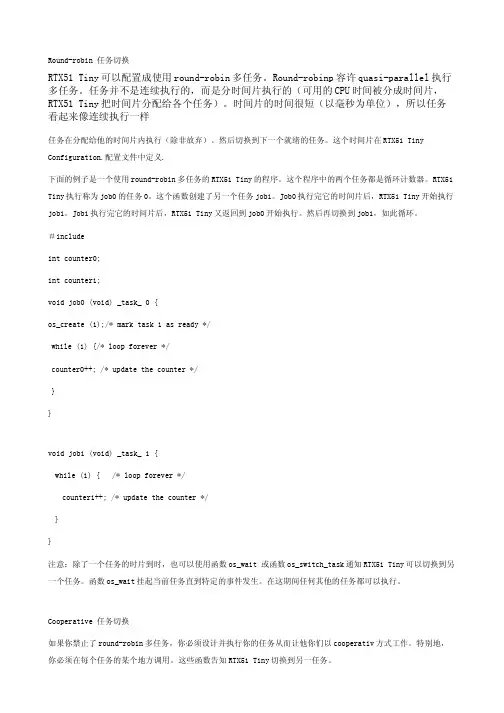
Round-robin 任务切换RTX51 Tiny可以配置成使用round-robin多任务。
Round-robinp容许quasi-parallel执行多任务。
任务并不是连续执行的,而是分时间片执行的(可用的CPU时间被分成时间片,RTX51 Tiny把时间片分配给各个任务)。
时间片的时间很短(以毫秒为单位),所以任务看起来像连续执行一样任务在分配给他的时间片内执行(除非放弃)。
然后切换到下一个就绪的任务。
这个时间片在RTX51 Tiny Configuration.配置文件中定义.下面的例子是一个使用round-robin多任务的RTX51 Tiny的程序。
这个程序中的两个任务都是循环计数器。
RTX51 Tiny执行称为job0的任务0。
这个函数创建了另一个任务job1。
Job0执行完它的时间片后,RTX51 Tiny开始执行job1。
Job1执行完它的时间片后,RTX51 Tiny又返回到job0开始执行。
然后再切换到job1,如此循环。
#includeint counter0;int counter1;void job0 (void) _task_ 0 {os_create (1);/* mark task 1 as ready */while (1) {/* loop forever */counter0++; /* update the counter */}}void job1 (void) _task_ 1 {while (1) { /* loop forever */counter1++; /* update the counter */}}注意:除了一个任务的时片到时,也可以使用函数os_wait 或函数os_switch_task通知RTX51 Tiny可以切换到另一个任务。
函数os_wait挂起当前任务直到特定的事件发生。
在这期间任何其他的任务都可以执行。
Cooperative 任务切换如果你禁止了round-robin多任务,你必须设计并执行你的任务从而让他你们以cooperativ方式工作。

rtx51 tiny原理RTX51 Tiny是一款基于RTX51内核的微型嵌入式操作系统。
本文将介绍RTX51 Tiny的原理及其应用。
一、RTX51 Tiny的原理RTX51 Tiny是由Keil公司开发的一款嵌入式实时操作系统。
它的设计目标是在51系列单片机上提供简单、灵活、高效的多任务管理和资源调度功能。
RTX51 Tiny使用了一种基于优先级的抢占式调度算法,能够实现多个任务之间的快速切换,从而提高系统的响应速度和并发处理能力。
RTX51 Tiny的核心是一个可重入的内核,它提供了任务管理、时间管理、资源管理和通信机制等基本功能。
任务管理器负责任务的创建、删除和切换,时间管理器实现了系统时钟的管理和定时器的功能,资源管理器用于管理共享资源的访问,通信机制则提供了任务间的消息传递和事件通知功能。
RTX51 Tiny的任务是用户定义的函数,可以是独立的任务或者中断服务函数。
每个任务都有一个优先级,优先级高的任务会优先执行。
当系统启动时,RTX51 Tiny会自动创建一个空闲任务,它的优先级最低,用于处理系统空闲时的任务。
RTX51 Tiny采用了一种事件驱动的方式进行任务调度。
当一个任务完成了它的工作或者等待某个事件发生时,它会主动让出CPU,将控制权交给调度器。
调度器会从就绪队列中选择优先级最高的任务执行,直到它完成了工作或者时间片用完。
RTX51 Tiny还提供了一些常用的服务函数,如延时函数、信号量函数、邮箱函数等,方便用户进行任务的同步与通信。
用户可以通过这些服务函数来实现任务间的协作和数据交换。
二、RTX51 Tiny的应用RTX51 Tiny广泛应用于各种嵌入式系统中,特别是对实时性要求较高的应用场景。
以下是一些常见的应用领域:1. 工业自动化:RTX51 Tiny可以用于控制系统中的任务调度和数据处理,实现复杂的自动控制算法和实时监控功能。
2. 智能家居:RTX51 Tiny可以用于家庭自动化系统中的任务管理和设备控制,实现智能家居的各种功能,如安防、照明和能源管理等。
单片机操作系统RTX51Tiny的使用步骤一般地,下面三步是使用RTX51 Tiny要实现的l 编写RTX51程序l 编译并连接程序l 测试和调试程序一、编写程序写RTX51 Tiny程序时,必须用关键字对任务进行定义,并使用在RTX51TNY.H中声明的RTX51 Tiny核心例程。
1、包含文件RTX51 Tiny仅需要包含一个文件:RTX51TNY.H。
所有的库函数和常数都在该头文件中定义。
你可以在你的源文件中包含它:#include2、编程原则以下是建立RTX51 Tiny程序时必须遵守的原则:①、确保包含了RTX51TNY.H头文件。
②、不要建立main函数,RTX51 Tiny有自己的mian函数。
③、程序必须至少包含一个任务函数。
④、中断必须有效(EA=1),在临界区如果要禁止中断时一定要小心。
参见概述中的中断一节。
⑤、程序必须至少调用一个RTX51 Tiny库函数(象os_wait)。
否则,连接起将不包含RTX51 Tiny库。
⑥、Task 0是程序中首先要执行的函数,必须在任务0中调用os_create_task 函数以运行其余任务。
⑦、任务函数必须是从不退出或返回的。
任务必须用一个while(1)或类似的结构重复。
用os_delete_task函数停止运行的任务。
⑧、必须在uvison中指定RTX51 Tiny,或者在连接器命令行中指定。
更多技术文档参见keil软件知识库。
3、定义任务实时或多任务应用是由一个或多个执行具体操作的任务组成的,RTX51 Tiny支持最多16个任务。
任务就是一个简单的C函数,返回类型为void,参数列表为void,并且用_task_声明函数属性。
例如:void func (void)_task_task_id这里,func是任务函数的名字,task_id是从0到15的一个任务ID号。
下面的例子定义函数job0编号为0的任务。
该任务使一个计数器递增并不断重复。
RTX51Tiny中⽂⼿册第六章函数参考以下部分描述RTX51 Tiny的系统函数。
函数依字母顺序排列,分为以下部分:概要(Summary)简述程序作⽤,列出包含的⽂件,包括它的声明和原型,语法举例,和参数描述。
描述(Description)程序的详细描述,如何使⽤。
返回值程序返回值说明。
参阅(see also)相关程序。
例⼦如何正确使⽤该函数的程序例⼦中断。
附注:●以os_开头的函数可以由任务调⽤,但不能由中断服务程序调⽤。
●以isr_开头的函数可以由中断服务程序调⽤,但不能由任务调⽤。
1、isr_send_signal概要: #includechar isr_send_signal(unsigned char task_id); /*信号发往的任务*/描述: isr_send_signal函数给任务task_id发送⼀个信号。
如果指定的任务正在等待⼀个信号,则该函数使该任务就绪,但不启动它,信号存储在任务的信号标志中。
附注:●该函数是RTX51 Tiny实时操作系统的⼀部分,仅包含于PK51中。
●该函数仅被中断函数调⽤。
返回值成功调⽤后返回0,如果指定任务不存在,则返回-1。
参阅 os_clear_signal,os_send_signal,os_wait例⼦#includevoid tst_isr_send_signal(void) interrupt 2{isr_send_signal(8); /*给任务8发信号*/}2、isr_set_ready概要 #include< rtx51tny.h>char isr_set_ready{ unsigned char task_id};/*使就绪的任务*/描述将由task_id指定的任务置为就绪态。
附注●该函数是RTX51 Tiny的⼀部分,包含在PK51中。
●该函数仅⽤于中断函数。
返回值⽆例⼦ #include< rtx51tny.h>void tst_isr_set_ready(void)interrupt 2{ isr_set_ready(1);/*置位任务1的就绪标志*/}3、os_clear_signal概要 #include< rtx51tny.h>char os_clesr_signal(unsigned cahr task_id);/*清除信号的任务*/描述清除由task_id指定的任务信号标志。