SIR-4000中文说明书
- 格式:docx
- 大小:3.75 MB
- 文档页数:28

SIR-4000中文说明书第一章简介1.1打开系统包装箱感谢您购买GSSI SIR@4000先生(以下简称SIR4000)。
货运箱中的装箱单包含您的订购的所有设备。
你应该根据装箱单检查你收到你的设备。
如果你发现一个项目或者是失踪了或者损坏,请立即通过电话或传真联系你的销售代表。
SIR4000系统包含:1、数字控制单元SIR4000主机1台2、运输箱1个3、电池2块4、充电器1个5、遮阳板1个6、操作指导书1本7、操作指导书CD1张8、GSSI优盘1个天线、电缆和数据后处理软件需要另外购买。
1.2简述SIR4000是一个轻便、便携式、地面透视雷达系统。
该系统兼容GSSI单一数字天线,单一的模拟天线,或双频率天线,有着广泛的应用领域。
系统将不支持操作数字和模拟天线同时使用。
SIR 4000的各种组件描述如下。
控制单元的主要特征是键盘,控制旋钮,和10.4英寸LED显示屏1024×768像素的分辨率,连接器面板(HDMI视频,USB 2.0,以太网,串行端口I / O,数字和模拟天线连接器、电力、GPIO连接器,usb),电池插槽,和指示灯。
,您可以查看实时数据或在回放模式。
尽管有遮阳板,但它在明亮的阳光下频幕也是清晰可见。
但是,长时间暴露于阳光直射会导致屏幕过热并可能影响屏幕可见性。
有两个自锁板的单元包含电池槽,usb端口和以太网端口。
打开面板,旋转锁销,直到它松了。
关闭面板按坚定,把锁销,旋转销,直到它收紧。
请参阅下面的图进行进一步的细节。
控制单元左侧是电池槽,可安置10.8 V可充电锂离子电池。
经过调查一个完全充电电池壳工作大约两个半小时(2.5h)。
2块电池是可通过电池充电器充电或通过控制单元和标准交流源AC适配器连接给单块电池充电。
电池充电的时间大约一个半到两个小时(1.5 - 2)。
在使用过程中一定要保持左侧和右侧面板覆盖单元关闭,以确保任何灰尘或污垢进入单位的内部。
兼容性SIR 4000不能与以下GSSI设备兼容:1、结构检测中:不能支持平板和电子阅读器2、不支持Y增益3、软件:SIR 4000的数据只能被radan7数据打开和处理,不支持radan5和6版本。
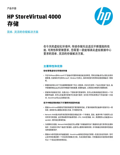
产品手册HP StoreVirtual 4000存储简单、灵活的存储解决方案在今天的虚拟化环境中,传统存储无法适应不断提高的性能、可用性和管理要求。
您需要一款能够满足虚拟数据中心要求的简单、灵活的存储解决方案。
主要特性和优势轻松管理虚拟化环境的存储• 平台与VMware和Microsoft®产品集成可提高存储功能及易用性,同时应用集成可以简化应用存储管理。
在虚拟化平台和Microsoft Windows®应用上,备份和回复与快照和远程复制集成一样轻松。
• 管理环境中的上百个节点就像管理前两个节点一样简单-无论它们在同一个站点还是多个站点。
集中管理控制台(CMC)可让您对存储进行轻松配置、管理和监控,从而简化日常操作并提高效率。
• 更新和升级轻松无忧。
仅需点击一下鼠标便可更新软件。
您可以在线将数据迁移到另一个存储硬件集群。
您可以在集群内更换节点来进行维护,也可在不停机的情况下升级到新一代技术。
StoreVirtual可以让您高枕无忧。
在不中断应用的情况下扩展阵列容量和性能• 借助StoreVirtual的横向扩展架构线性扩展容量和性能。
扩展存储如同在集群中添加节点一样简单,因而您可以随着业务增长无缝、不中断地扩展。
• Network RAID技术将所有资源和容量全部集合到一个存储池。
因此,集群中每个卷都可以访问所有可用容量。
这还意味着所有集群资源-CPU、RAID控制器、NIC、高速缓存以及磁盘(diskspindle)-都可能会影响性能。
• 为消除单点故障,Network RAID功能还可以跨整个存储集群对多个数据拷贝进行条带化处理和保护。
冗余是针对每个卷进行管理的-这样可以提高存储利用率,并可根据应用的要求匹配适当的卷数据保护。
• 借助iSCSI和可选的光纤通道连接,StoreVirtual能够出色地运行即使-在混合协议环境中。
您可以在所有位置部署一个灵活的存储解决方案。
为未来做好准备-不用重新设计或更换存储便可从一个协议迁移到其他协议。
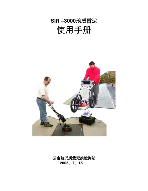
SIR –3000地质雷达使用手册云南航天质量无损检测站2005.7.15SIR –3000地质雷达使用手册说明本说明书是在GSSI提供的中文板的基础上校编而成,修改了原说明书译文中的错误,现发给各项目部,仅限公司内部使用,不得外传。
SIR –3000地质雷达使用手册第一部分引言 (1)1.1 拆封系统 (1)1.2 总的描述 (1)第二部分启动和TerraSIRch 模块设置 (5)2.1 硬件设置 (5)2. 2 启动和屏幕显示 (6)2. 3 系统模式和菜单:总的描述 (8)系统菜单 (8)采集菜单................................................................................. .. (9)回放菜单....................................................................................... .14 输出菜单................................................................................. ....... .15 第三部分:采集数据系统设置 (20)3.1 用于二维采集的设置 (20)3.2 用于三维采集的设置 (22)3.3 基于时间数据采集的设置 (22)3.4 点数据采集的设置 (23)第四部分:数据传送和文件维护 (24)4.1 通过USB连接传送到PC机 (24)4.2 通过外部压缩闪光卡传送到PC机 (24)4.3 通过外部USB 钥匙链驱动传送到PC机 (24)4.4 从系统删除数据 (25)第五部分:预置参数模式汇总 (25)5.1 混凝土扫描 (25)5.2 构造扫描 (27)5.3 常用设施扫描 (27)5.4 地质扫描 (28)第六部分:在SIR-3000上使用GSP全球定位系统 (29)附录A:TerraSIRch SIR-3000 系统技术规格 (30)附录B:野外测量的基本知识 (32)附录C:把SIR-3000安装到手推车上 (36)附录D:常见材料的介电常数和术语集 (42)附录E:天线参数列表 (44)附录F:术语集和进一步阅读的建议 (49)附录G:在PC机上安装微软的ActiveSync (53)第一部分引言该手册既适用于探地雷达(GPR)的新用户,也适用于有经验的用户。
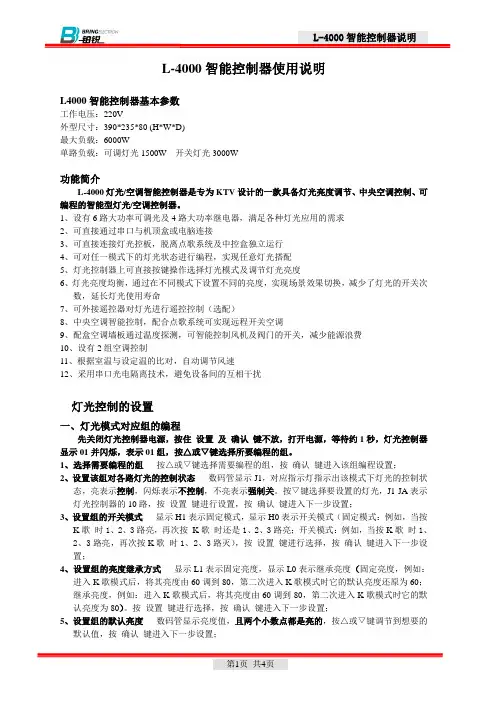
L-4000智能控制器使用说明L4000智能控制器基本参数工作电压:220V外型尺寸:390*235*80 (H*W*D)最大负载:6000W单路负载:可调灯光1500W 开关灯光3000W功能简介L-4000灯光/空调智能控制器是专为KTV设计的一款具备灯光亮度调节、中央空调控制、可编程的智能型灯光/空调控制器。
1、设有6路大功率可调光及4路大功率继电器,满足各种灯光应用的需求2、可直接通过串口与机顶盒或电脑连接3、可直接连接灯光控板,脱离点歌系统及中控盒独立运行4、可对任一模式下的灯光状态进行编程,实现任意灯光搭配5、灯光控制器上可直接按键操作选择灯光模式及调节灯光亮度6、灯光亮度均衡,通过在不同模式下设置不同的亮度,实现场景效果切换,减少了灯光的开关次数,延长灯光使用寿命7、可外接遥控器对灯光进行遥控控制(选配)8、中央空调智能控制,配合点歌系统可实现远程开关空调9、配盒空调墙板通过温度探测,可智能控制风机及阀门的开关,减少能源浪费10、设有2组空调控制11、根据室温与设定温的比对,自动调节风速12、采用串口光电隔离技术,避免设备间的互相干扰灯光控制的设置一、灯光模式对应组的编程先关闭灯光控制器电源,按住设置及确认键不放,打开电源,等待约1秒,灯光控制器显示01并闪烁,表示01组,按△或▽键选择所要编程的组。
1、选择需要编程的组按△或▽键选择需要编程的组,按确认键进入该组编程设置;2、设置该组对各路灯光的控制状态数码管显示J1,对应指示灯指示出该模式下灯光的控制状态,亮表示控制,闪烁表示不控制,不亮表示强制关。
按▽键选择要设置的灯光,J1-JA表示灯光控制器的10路,按设置键进行设置,按确认键进入下一步设置;3、设置组的开关模式显示H1表示固定模式,显示H0表示开关模式(固定模式:例如,当按K歌时1、2、3路亮,再次按K歌时还是1、2、3路亮;开关模式:例如,当按K歌时1、2、3路亮,再次按K歌时1、2、3路灭),按设置键进行选择,按确认键进入下一步设置;4、设置组的亮度继承方式显示L1表示固定亮度,显示L0表示继承亮度(固定亮度,例如:进入K歌模式后,将其亮度由60调到80,第二次进入K歌模式时它的默认亮度还原为60;继承亮度,例如:进入K歌模式后,将其亮度由60调到80,第二次进入K歌模式时它的默认亮度为80)。

Instruction Manual 4000 Series Digital Portable AnalyzerService Department(800) 458-6153 ext. 121(818) 882-2331 ext. 121FAX(818)341-0642E-mail:************************THIS P AGE INTENTIONALL Y LEFT BLANKTABLE OF CONTENTSSECTION TITLE PAGE1.0 Equipment DescriptionFront Panel 4Rear Panel 6Right Side Panel 7Internal components 8 2.0 Operating InstructionsSetting the Alarm 9Zeroing the Instrument 10Sampling 11 3.0 CalibrationIntroduction 12Sample Bag & Pressurized Cylinder Calibration 14Calibration Procedure 15 4.0 General MaintenanceBattery Life 16Battery Charging & Replacement 16Water loss in Refillable Sensors 18Long Term Storage 23Post Storage Startup 235.0 Troubleshooting 246.0 Warranty 257.0 Return Authorization 268.0 AppendixINTERFERING GAS DATA 27SCRUBBER INFORMATION 31Note:It is not necessary to calibrate the monitor whenreceived from the Interscan or an authorized distributor.All Interscan monitors are calibrated at the factory prior toshipment.The Interscan 4000 Digital series operates on the principle of pullinga sample (Sample draw) through a sensor. The Electrochemicalsensor is manufactured by Interscan. Electrochemical means thatit produces an electrical current proportional to the level of gaspassing through. The large size of the Interscan sensors results inlarger reactive surface area which yields greater sensitivity. Equipment Description(fig. 1)Designation FunctionLCD Display:Indicates gas level when function switch is inZERO, SAMPLE INACTIVE or SAMPLEACTIVE, and battery level when on BAT.TEST A or B.ALARM Light:LED. Flashes ON/OFF when alarm setpoint is exceeded.ALARM SET:25-Turn potentiometer with a screwdriveradjustment. Sets the alarm trip point at thedesired gas level. (low alarm set must begreater than 5% of the full scale).SPAN/CAL:25-Turn potentiometer with a screwdriveradjustment. Sets display to correspond to theconcentration of the calibration gas used forcalibrating the instrument or to the levelspecified on ECS certificate.FUNCTION SWITCH:Rotary switch as follows:OFF:Analyzer power is OFF.SAMPLEINACTIVE:Analyzer power is ON (pump is OFF),Sampling is inactive.SAMPLEACTIVE:Analyzer power and pump are on. Also in thisposition the analyzer is zeroed. Samplemeasurements and calibration areaccomplished in the sample mode.BAT.TEST A:Indicates state of charge of the Nickel-Cadmium (NiCd) batteries on the LCDDisplay. These batteries power the pump &alarm. Recharge if the LCD Display level fallsto or below 100 (ignore decimal point).BAT. TEST B:Indicates state of charge of the “C” sizealkaline batteries on the LCD Display. Thesebatteries power the main circuitry, display andare NOT re-chargeable. Replace if the LCDDisplay level falls to or below 100 (ignoredecimal point). You must allow an overnightstabilize prior to use if the batteries arereplaced. Batteries are to be checkedevery 30 days.ZERO:10-Turn Potentiometer. Allows the meter to beadjusted to zero, by compensating for anybackground signal.(fig. 2)Designation FunctionINLET:¼” O.D. Quick connect or compression gasfitting.OUTLET:¼” O.D. Quick connect or compression gasfitting.RECORDER OUTPUT:¼” phone jack for Analog recorder outputconnection. Typically 0-100mV. Tip –positive, Ring – ground.CHARGER INPUT: 3.5mm phone jack for 9V DC, 100mA chargerinput. Tip – positive, Ring – ground.SENSOR SCREWS:Used to hold Sensor or Sensor base in place.(fig. 3)AUDIBLE ALARM:Piezoelectric Horn, sounds when alarm setpoint is exceeded.The above (fig 3) page 7, #12 indicates two #1 Phillips-head screws located on the right side panel. Removing these screws allows access to the internal components. Do not remove any other screws(fig. 4)Operating InstructionsNormally, the alarm is set at the Factory at 50% of full scale. Thealarm can be reset to any desired level by following the procedurebelow. Minimum alarm level must be greater than 5% of the fullscale measuring range.Set FUNCTION switch to SAMPLE INACTIVE. Using the ZEROcontrol, advance the LCD display to the desired alarm set point.Some analyzers require the use of span tool (provided). Adjust theALARM SET (fig. 1 pg. 4)control until the alarm sounds. Adjust theZERO control slightly counterclockwise until the alarm is silent. Toconfirm setting slowly adjust the ZERO control clockwise until thealarm sounds. Re-adjust the ALARM SET control if necessary.Adjust the ZERO control for a reading of “0” on the display.The Analyzer must always be zeroed, prior to use.Zero adjustments must be made in the SAMPLE ACTIVE mode,i.e. with the pump on, in air free of interfering gases. If necessary,use zero air or a C-12 filter (provided) to zero in the sampling area.When using C-12 zero filter, connect externally to gas inlet. Allowreading to stabilize, before making final zero adjustment,(stabilization can take approximately 20 minutes). The C-12 filtermust be removed after zeroing the analyzer.Analyzer must be zeroed prior to sampling (section 2.1).Set the FUNCTION switch to SAMPLE ACTIVE to activate the pump. If the INLET or OUTLET is blocked, the pump may stall. Note: Running the Analyzer with blocked INLET or OUTLET may lead to the sensor leaking caustic electrolyte leading toanalyzer damage.Power analyzer off, and clear the blockage. To reset the pump, set the FUNCTION switch to SAMPLE INACTIVE momentarily and then switch again to SAMPLE ACTIVE.Nominal sample rate in MOST analyzers is approximately 1.0, ±0.2 liter per minute. NOTE: For hydrazine analyzers with the measuring range of 0-100ppb the sample flow rate is 2.2 ± 0.2 liters per minute.The Average sample run time, starting with fully charged “C” NiCd batteries, is 12 hours. If the BATTERY TEST “A” indication is down to 100 on the LCD display, the flow rate may have started to decrease. This is usually not a problem unless very precise readings are required.Sampling from high pressure may only be achieved by using the method indicated in (fig. 5).Note: The sample to the Interscan Analyzer must be drawn perpendicular to the Sample flow stream.(fig. 5)CalibrationAll analyzers are factory calibrated prior to shipment.There is no easy answer as to how often a monitor should becalibrated. This is strictly a function of the application (gasconcentration and frequency of exposure to target gas). Thepurpose for calibration is to compensate for any possible decreasein sensor sensitivity. The primary cause of sensitivity decrease isexcessive loss of water by evaporation. A secondary cause maybe by contamination from unknown sources. H2S sensors show anadditional decrease in sensitivity due to internal sulfur formation, therate of which depends on the gas concentration.Interscan’s SENSOR EXPRESS® program streamlines downtimeby sending you a pre-calibrated sensors on a regular basis per yourneeds, without the burden of returning sensors to our factory for re-certification. The sensors are shipped to you either twice , threetimes, or four times per year at your discretion.Follow the instructions received with the Sensor, allow to stabilize,and the instrument is ready for use. The factory recommendedprocedure for calibrating all INTERSCAN analyzers, involves theuse of certified calibration gas or a permeation device. Besidesbeing essential for calibration, having a known certified gasstandard on hand allows the user to test the analyzer at any time todetermine that it “really works”As indicated on the certification sheet, the Sensor Express®. It doesnot certify the analyzer as a whole. Most importantly, the SensorExpress® program is not a substitute for basic analyzermaintenance, nor does it check for malfunction of the analyzercomponents.Whatever the source of calibration gas, the recommended method is to collect the gas in the proper sample bag, which is then attached to the analyzer INLET. The calibration gas is drawn from the proper sample bag through the sensor. An exception to the use of a sample bag is for those gases, which are reactive with, or chemisorbed by the bag itself (e.g. Chlorine, Hydrazine). Teflon® or Tedlar® bags are suitable for H2S, SO2, NO and NO2. Several bag materials are suitable for CO. Contact the Factory for recommendations.The sample bag method is the factory-recommended method for calibration. Since an internal pump is used, the same flow rate conditions during the sample and the calibrate modes are assured, eliminating errors due to flow rate differences. For most applications, using a bag is the simplest procedure.A regulated pressurized certified cylinder fitted with a tee-manifold (fig. 6) and unrestricted vent is a good procedure in place of the sample bag, as long as the flow rate of the gas is at least 140 percent that of the sample pump.(fig. 6)Analyzer must be zeroed prior to calibration (sec 2.1).1. For all gases, except Chlorine or other chemisorbable types, fill the 5 litersample bag with calibration gas, and attach it to the external inlet fitting.This is best done by attaching a short length 4 inch (101.6mm) of 1/4 inch(6.35 mm) O.D. Teflon tubing to the sample bag, then inserting into theinlet fitting.2. Set the FUNCTION switch to SAMPLE ACTIVE.3. Allow 2 to 3 minutes for the reading to stabilize, and by using theSPAN/CAL control, set the display to match the calibration gas concentration being used.4. Remove the sample bag from the analyzer and allow the display tostabilize.5. The analyzer is now calibrated and set up for operation.NOTE: If you require additional information on Calibrationprocedures, please contact the Service Department at 1-800-458-******************************************General MaintenanceBecause of current requirements of the circuitry, “C” size alkalinebattery life should be check on a monthly basis, whether the unit isoperating or not. Note: Batteries vary in capacity bymanufacturer and may provide more battery life. Analyzermalfunction, as a result of low battery, will be evident as eitherinability to zero the monitor or clipping of the display at a fixedreading below full scale.Nickel-cadmium battery life is indeterminate. It is somewhatdependent upon how well the charge level is maintained.All models of the 4000 Series analyzers use two “C” size alkalinebatteries. These are located on the hinged door, right side (fig. 4 pg.8). Polarity is marked on the door over the battery holder.A few minutes warm-up/stabilization is needed before using theanalyzer if alkaline batteries are replaced before Battery Test “B”indicates a low battery condition (100). Replace “C” alkalinebatteries and allow monitor to stabilize overnight if the batteries arelow or dead. The FUNCTION switch should be set to OFF duringthis time. This is performed to allow the sensor time to stabilize.The rechargeable batteries are ½ “C” size NiCd and are rated at0.80 ampere hours. They are mounted on the hinged door, left side(fig. 4 pg. 8). Polarity is marked on the door, over the battery holder.All models use four ½ cell “C” size NiCd batteries. Condition isshown in the BATTERY TEST “A”, FUNCTION switch position. TheNiCd battery voltage changes quite rapidly as it approaches therecharge point, which makes accurate display indication difficult. Itis recommended that the batteries be recharged if the reading inBATTERY TEST “A” is at 100 (ignoring the decimal place). Allowingthe reading to drop below 100 is not recommended. Note: NiCd batteries can develop cell memory. Cell memory is caused by running the analyzer on battery power for a short period of time REPEATEDLY i.e: Running the analyzer for 20 minutes and then recharge. If this occurs repeatedly, the NiCd battery life will only retain a 20 minute charge memory.The charger is an external 9V DC, 500mA transformer and is connected to the rear of the unit prior to charging. The tip is positive and the ring ground. The FUNCTION switch should be set to OFF or SAMPLE INACTIVE when charging. The recommended charge time is 16 hours.(fig. 7)All sensors provided with a fill port require that the electrolyte matrix is maintained in a near-saturated condition in order to provide optimum performance. This is achieved by injecting distilled or deionized water into the sensor via the red plug, using the plastic syringe (provided).Refer to (fig. 7 pg. 16). Refillable sensors are identified by the red fill plug in the side of the sensor. The fill plug location may vary from(fig. 7 pg. 16). There are two types of refillable sensors. The S-type is a shorter sensor of slightly over 2 1/2 inches ( 64 mm) in height; the P-type is almost 4 inches (104 mm) in height. “P” and “S” type sensors connect to the analyzer by different connection methods.For portable survey monitors, the sensor should be removed and weighed every 1 to 2 months, depending upon usage. The weight loss is indicated on the weight label on the side of the sensor. Sensor weight is restored be removing the sensor from the analyzer and comparing the current weight of the sensor with its original weight (in grams). Sensor weight is indicated on a label located on the side of the sensor.There are three types of gas fittings used depending on the age of the original sensor and the gas being measured.(fig. 8)Male elbow ¼ O.D. tube compression fittingThis is a compression fitting comprised of the body, nut and two ferrules (fig. 8). Disconnect by loosening the nut until the tubing can be pulled away from the body. To re-attach insert the tubing and tighten the nut. Do NOT over tighten the nut as this will damage the nut and fitting(fig. 9)Quick connect male elbowThis is a quick connect system comprised of the body, o-ring and ferrule (fig. 9). Disconnect by pushing on the ring where the tubing enters the fitting and gently pulling on the tubing. Re-attach by inserting the tubing all the way in and then gently pull backward.(fig. 10)Barbed male elbowThe fitting uses a barbed connector system (fig. 10). Disconnect by pulling on the tubing. Re-attach by pushing the tubing onto the fitting until firmly seated.Fig. 11For P-type sensors refer to (fig. 11). Disconnect the 2 electrical connections to the sensor. Disconnect the tubing from each gas fitting. Loosen the screw indicated as “A”. Loosen the clamp screw “B” until the sensor can be removed from clamp.NOTE: DO NOT REMOVE ANYTHING ELSERestore the sensor to within 5 grams original sensor weight by injecting an equivalent cc of distilled or deionized water (10g. weight loss means add 10cc water). DO NOT OVERFILL. If sensor will not take on any more liquid (liquid starts coming out the fill port) do not attempt to add additional distilled water.Note: Weight loss in excess per sensor weight label may prevent the restoration of the weight to within 5 grams of the original weight.DO NOT OVERFILL. After weighing and refilling replace the sensor in the analyzer, tighten screw “B” taking care only to make it tight so as to secure the sensor. Then tighten screw “A”, do not over tighten.Assure that all electrical and pneumatic fittings are secure. The sensor should be allowed to stabilize forseveral hours with power off.(fig. 12)For S-type sensors refer to (fig. 12). Disconnect the two electrical connections to the sensor. Disconnect the tubing from each gas fitting. Remove the two Sensor Screws (# 7).NOTE: DO NOT REMOVE ANYTHING ELSE!!Restore the sensor to within 5 grams original sensor weight by injecting an equivalent cc of distilled or deionized water (10g. weight loss means add 10cc water). DO NOT OVERFILL. If sensor will not take on any more liquid (liquid starts coming out the fill port) do notattempt to add additional distilled water.Note: Weight loss in excess per sensor weight label may prevent the restoration of the weight to within 5 grams of the original weight.DO NOT OVERFILL. After weighing and refilling replace the sensor in the analyzer, tighten screws on the rear of the analyzer. Assure that all electrical and pneumatic fittings are secure. The sensor should be allowed to stabilize for several hours with power off.Turn FUNCTION swit ch to “OFF” position. Disconnect charger from analyzer. Detach 15 pin “D” connector from circuit board. Remove alkaline batteries and cover analyzer to protect from dust.24 Hours Before Using:Uncover the analyzer. Install FRESH alkaline batteries. Reconnect 15-pin “D” connector from circuit board. Connect the charger to the analyzer to charge NiCd batteries.After 24 Hours:Follow instructions in Section 2.0. Analyzer is ready to use or calibrate.WarrantyINTERSCAN CORPORATION warrants portable analyzers of itsmanufacture (sensors, batteries, fuses, lamps, tubing, fittings,filters, and scrubbers excepted) to be free from defects in materialand workmanship for a period of one year from date of shipment.INTERSCAN CORPORATION warrants sensors of its manufactureto be free from defects in material and workmanship for a period ofsix months from date of shipment.INTERSCAN CORPORATION'S sole obligation under thiswarranty is limited to repairing or replacing, at its option, any itemcovered under this warranty, when such item is returned intact,prepaid to the factory (or designated service center).This warranty does not apply to any of our products which havebeen repaired or altered by unauthorized persons, or which havebeen subject to misuse, negligence, or accident, incorrect wiring byothers, installation or use not in accordance with instructionsfurnished by the manufacturer, or which have had the serialnumbers altered, effaced or removed. The sensors are factorysealed and must not be opened or modified in the field for thewarranty to remain in effect. This warranty is in lieu of all otherwarranties, whether expressed or implied.Additionally, in a custom system, warranty on any component shallnot exceed the manufacturer's warranty given to INTERSCANCORPORATION.Return AuthorizationAll returns for repairs require a "RETURN AUTHORIZATIONNUMBER" issued by the INTERSCAN Service Department uponrequest. Below is the link to the RMA form:/contact/index.phpThis is done primarily to cause the user to contact the factorydirectly. The reason for this is that a high percentage of serviceproblems are resolved over the telephone, avoiding the need forreturning the analyzer or part.Should return of the analyzer or part be advised by the ServiceDepartment, the "RETURN AUTHORIZATION NUMBER" willexpedite prompt return of the repaired unit.For service information, please contact:INTERSCAN CORPORATIONService Department(800) 458-6153 ext. 121(818) 882-2331 ext. 121FAX(818)341-0642E-mail:************************Appendix AINTERFERING GAS DATANo analytical method is completely specific. Gases present in the environment, other than the "target" gas of measurement, may affect analyzer response. Interferences are not necessarily linear, and may also exhibit time dependent characteristics.The charts that follow detail the approximate concentration in parts per million of interfering gas required to cause a 1 ppm deflection in the chosen analyzer. In many cases, specificity can be improved. Please note that the response values given are not absolute, and may vary depending on sensor formulation.The special case of how alcohols affect electrochemical sensors is discussed in this Knowledge Base article. ()For further information on the effects of interfering gases, please contact the factory.The charts follow the format, and grouping of gases, that was originally established in early Interscan print brochures.Chart 1: CO, Cl2, ClO2, H2, H2S, NO, NO2, O3, SO2 analyzersChart 2: Ethylene oxide (EtO) (C2H4O) analyzersChart 3: Formaldehyde (HCHO) analyzersChart 4: HCl, HCN, hydrazine analyzersChart 5: C2H4 (ethylene) analyzers(1) Data shown for H 2S models with ranges higher than 0-1999 ppb (2) Data shown for H 2S models with ranges of 0-1999 ppb and lower‡ = Hydrocarbons¤ = Rejection ratio can be improved electronically¶ Isopropyl alcohol represents the most significant interference on the ethylene oxide sensor, but in nearly all cases, potential problems can be overcome. Typical remedial actions include:a. Point shutdown/automatic restart, which allows the operator to temporarily interrupt monitoring at points that could be affected when isopropyl alcohol is used. Monitoring restarts automatically on a time-adjustable basis.b. Selection of monitoring points away from those areas that may be unduly affected by isopropyl alcohol.c. Using alternative germicides, which do not contain isopropyl alcohol.The EtO sensor may also respond to strong odors of colognes and perfumes, and to certain floor strippers and waxes. Refer to guidelines above covering isopropyl alcohol. Remember that you are attempting to monitor parts per million levels of ethylene oxide in an environment that may contain percent (10,000 ppm = 1 percent) levels of these potentially interfering compounds.= Negative interference= Negative interference § = Scrubber available= Negative interference= Negative interferenceAppendix B SCRUBBER INFORMATION。
GSSI探地雷达作业指导书(SIR-4000)浙江省交通运输科学研究院2016 年08 月目录一、SIR-4000外业采集仪器操作步骤 (3)1.1仪器连接 (3)1.2数据采集 (3)1.3数据回放 (5)1.4数据传输 (5)1.5关闭仪器 (6)二、SIR-4000内业数据处理操作步骤 (6)2.1源目录和输出目录设置 (6)2.2检查现场标记 (7)2.3调整贴合面时间零点 (7)2.4时深转换 (8)2.5距离归一化 (8)2.62D交互式解释 (9)2.7导出数据 (10)三、现场检测注意事项 (10)四、现场安全注意事项 (11)一、SIR-4000外业采集仪器操作步骤1.1仪器连接连接主机、电缆、天线,标记器、测量轮。
开机。
安装电池或者外接电源,按电源键仪器自动开机进入主界面。
图 1 开机主界面1.2数据采集1.2.1现场采集基本步骤数据采集和保存文件。
选择新建项目或最近已用设置→进入采集参数设置界面→调整仪器参数(选择天线类型和设置增益)→按START键开始移动天线采集数据→采集结束后,长按STOP键保存数据。
采集过程中做好野外现场记录。
1.2.2仪器参数设置界面(1)选择天线类型。
(2)新建项目后,编辑项目名称。
(3)进入参数设置界面,设置增益,然后正式开始采集。
图 4 增益界面,开始采集1.3数据回放现场采集完成后用数据回放功能检查数据的有效性。
进入主界面,按回放按钮,弹出对话框,利用上下键找到相应的文件,利用旋钮选择键选中文件,面板Enter键确认,按Start键来回放数据。
1.4数据传输将U盘插入仪器左上角位置的USB接口内,进入回放模式(图5),点击复制至USB所对应的按钮,传输完成。
图 6 数据传输界面1.5关闭仪器按STOP键回到主界面后,长按电源按钮直到主机关闭(约3秒)后松开按钮,关闭主机。
收仪器。
二、SIR-4000内业数据处理操作步骤2.1源目录和输出目录设置打开软件RADAN7,选择源目录和输出目录,设置文件读取目录和文件存放目录。
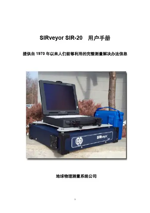
SIRveyor SIR-20 用户手册提供自1970年以来人们能够利用的完整测量解决办法信息地球物理测量系统公司限定的担保或保修责任和约束的限制地球物理测量系统公司在下文称之为GSSI保证从交给买方的交货日期起12个月内GSSI的产品将不会出现材料和工艺方面的故障除上述的限制担保之外GSSI拒绝所有的担保明确的或暗指的包括任何销路的担保或为特定目的合理性的担保GSSI的义务是被限定在修理或更换那些被返回的元件或设备上已预付运输和保险费没有变更和进一步损坏和那些按照GSSI的看法是有缺陷的或在正常使用期间变得有缺陷的元件或设备上GSSI以为不管设备是否有缺陷只要是因设备适当的或不正确的操作所引起的任何直接间接特殊的偶然的或随之发生的损坏或损伤都不负赔偿责任在给GSSI返回任何设备前必须先取得返回材料授权RMA的编号请打电话给GSSI 用户服务经理他将分配一个RMA编号务必拥有设备的有效序列编号版权2002地球物理测量系统公司保留任何形式的全部或部分复制的权利出版者地球物理测量系统公司美国新罕布什尔州北塞勒姆North Salem克来因高速路13号邮编03073-0097印刷地美国GSSI和SIR是地球物理测量系统公司的注册商标联邦通讯委员会的A类服务或顺从性该设备遵守联邦通讯委员会规则的第15部分操作服从下列两个条件1该设备不可以引起有害的干扰2该设备必须接受任何接收的干扰包括可以引起不希望有的干扰警告若用户对该设备的改变或修改没有明显地得到担负服务一方的同意就可能取消这个用户操作该设备的权利注释该设备经过测试后发现依据FCC规则的第15部分它遵守A类数字设备的限制当该设备在商业环境中操作时这些限制被用来提供对有害干扰的合理保护该设备产生利用和能辐射无线电频率的能量如果其安装和使用与介绍手册的不一致则会造成对无线电通讯的有害干扰在住宅区操作该设备可能会引起有害干扰在这种情况下使用者将被要求自费校正该干扰该设备必须配用屏蔽电缆以保证符合A类的FCC限制协作要求a在设备使用前超宽频带UWB成像系统需要通过FCC的协作操作员将遵守由该协作引起的设备用法上的任何约束b UWB成像设备的用户将给FCC工程和技术办公室提供详细的操作区域该办公室将通过国家电信和信息管理局与联邦政府协商该信息UWB操作员提供的信息将包括用户的名字地址和其它有关的联系信息要求施工的地理区域以及UWB设备的FCC 标志号码和其它名称该材料将被提交到下列地址美国华盛顿哥伦比亚特区20554西南第12大街445号联邦通讯委员会OET 频率协作部门注意: UWB协作(d )已授权协调的UWB系统用户可以把这些系统转移到其他合格的用户转移到基于所有权改变的协作之上的不同地点或转移到有授权操作的联邦通讯委员会和协作的地点e NTIA/联邦通讯委员会的协作报告将包括适用于日常操作的任何所需的约束这种约束可能指定被禁止操作的区域或该约束可能指定位于无线电台附近的区域对这些区域在UWB设备操作前还需要做附加的协作如果需要附加当地的协作则还将提供当地的协作联系f) 从接到NTIA的协作请求起常规的UWB 作业的协作将不会长于 15个工作日特殊暂时的操作可以用一个快速的环境许可的往返时间来处理在包括生命安全和财产安全处于紧急情况时UWB 系统的作业可以先发生而不用事先为一个类似于CFR47节2.405 (a)-(e)的UWB 设备用户遵守的通知过程作准备加拿大的发射要求这台A类的数字仪器遵守加拿大的 ICES-003目录第一部分启动和基本项目的安装 11.1 系统启动 11.2 软件和新项目设置 1目录长度和数据库的系统设置 21.3 创建新项目 5标定测量轮7定位\ 测程10测程增益10滤波器11静态叠加11 1.4 打开已存在的项目文件13 1.5 运行当前的项目文件15 第二部分数据采集格式17 2.1 单一的二维文件格式17创建新文件和设置数据采集参数17开始采集数据17插入标记17备份光标仅随测量轮使用18关闭和保存一个数据文件18 2.2 数据采集三维文件格式19定义一个三维项目19开始采集数据21对界面干扰的有效编辑22关闭和保存一个数据文件23 2.3 做超三维分析需补充的数据采集步骤25 附录A SIRveyor 技术规格27 附录B SIRveyor用于数据采集的电源和配置29 附录C采样道排列形式33 附录D装好的SIR-20配置35 附录E创建和编辑宏命令41 附录F在SIR-20上使用通用雷达43 附录G普通材料的介电值和术语集45 附录H数据处理和成像49 附录I SIRveyor 命令按钮51注释SIRveyor System Operation SIRveyor 系统操作Create New Project 创建新项目Open Existing Project 打开已存在的项目Run Current Project 运行当前项目 Data Collect Mode 数据采集模式Setup Parameters 设置参数Data Collection Parameters 数据采集参数Project 项目 Attach Macro 附加宏Setting Review – System Initialization 设置复查系统初始化Run 运行 Save & Stop保存和停止 Delete & Stop删除和停止第一部分启动和基本项目的安装SIRveyor SIR 20 是有2 个硬件道天线4个记录道的高性能地质雷达GPR系统SIRveyor用来记录处理和显示地下特征的剖面和三维图象如果有三维格式采集的资料该系统配有标准的GSSI天线能用于各种应用领域来解决复杂的地下探测问题和构造探测问题SIRveyor允许我们采集由一个天线采集到4道的数据由两个天线采集到4道的数据二维格式的单一剖面三维格式数据的采集野外处理数据复查和显示二维剖面或三维格式的野外数据1.1 系统启动1把选择的电源连接到SIRveyor SIR-20设备上当只有掌上电脑电池时系统不运行2接通计算机开关位于以太网连接器后边计算机右部的后面3一旦计算机接通并且SIR-20已插入则系统就运行4过几分钟显示器灯将闪两下然后就保持稳定了更多的信息请查附录B1.2 软件和新项目设置先打开RADAN系统信息屏幕就可找到软件版本和序列号该屏幕将在30秒后消失或点击鼠标左键跳到下一屏幕为了采集数据特别设置了SIRveyor 的快捷键虽然RADAN软件屏幕和SIRveyor 的屏幕好象相同但两者的配置是不同的因而数据不能通过RADAN 快捷键采集目录长度和数据库的系统设置这些命令使你能安装系统以便在新地区收集数据如果你希望继续做先前的项目就跳到1.4部分打开存在的项目文件否则就按以下步骤进行第一步是设置数据目录对每个工区或每项工作创建新的数据目录会使管理数据更容易应该先指定一个单独的输出目录路径以便让软件将已处理的数据放到该输出目录1设置文件信息选择视窗>Customize用户自选2选择目录表然后设置源目录和输出目录注释Customize 用户自选Directories 目录Appearance 状态外观Database 数据库Linear Units 长度Source 源目录Output 输出目录OK确定Cancel取消Apply应用Help 帮助3选择长度单位列表然后设置想要的单位注释Customize 用户自选Directories 目录 Appearance 状态外观Database 数据库 Linear Units 长度单位Vertical 垂直Horizontal 水平OK确定Cancel取消Apply应用Help 帮助 METER 米CM 厘米INCH英寸 FOOT英尺YARD码4选择数据库列表然后点击要选择的临时数据库标记选项注释No Markers Informaion 无标记的信息Temporary Markers Database临时标记数据库Permanent Markers Database永久标记数据库Customize 用户自选Directories 目录 Appearance 状态外观Database 数据库 Linear Units 长度单位OK确定Cancel取消Apply应用Help 帮助5一旦正确地设置了这些软件参数就继续到下一节完成新项目的设置注释Step 1 Create New Project 第一步创建新项目Step 2 Create New Project file 第二步创建新项目文件3D Project File 三维项目文件Step 3 Data Collection Mode 第三步数据采集模式Step 4 Data Collection Parameters 第四步数据采集参数Step 5 Attach Macro 第五步附加宏指令Step 6 Setting Review – System Initialization 第六步设置复查系统初始化Step 7 Run 运行 Save & Stop保存和停止 Delete & Stop删除和停止1.3 创建新项目第一步创建新项目为了开始一个新项目选择FILE菜单下的New 或点击New Collect对一个新的三维项目必须点击Create 3D File ,请参阅2.2节第二步创建新项目文件1进入项目文件名在合适的输入框内键入唯一的项目文件名然后点击Save保存?? 如果已经存在一个相同文件名的文件则将提醒你取代老的文件或改变为新文件名注释位于该窗口底部的CollectData Files命令框会自动检查它不能关闭注释 Create New Data Collection Project创建新的数据采集项目1Type project name 键入项目名2Save 保存2在点击Save后项目信息对话框就会打开,见下图.注释Project Information 项目信息1 Check path 核对路径2 Change ,if required 如果需要就改变3 All white fields are optional 所有空白的方框都是任选的4 Click OK 点击OK3该窗口允许我们检查文件在计算机里被保存的位置(路径).也允许设置测量时间,题目,和任何能在处理或解释期间起帮助作用的注释.这些区域(字段)都是可选择的.4点击OK, Select Data Collect Mode 对话框就打开了.第三步:数据采集模式数据采集模式对话控制数据采集方式?? Free Run 连续采集数据?? Point Mode点测?? Survey Wheel 测量轮?? GPSLog 参见附录F注释测量轮方式除了为三维成像采集数据外还必须与构造扫描系统软件一起来使用Free Run数据是基于设置在文件宏中的每秒扫描时间和次数来采集的即使处于稳定状态只要采集状态开关是开着的天线就总是不断进行采集Point Mode随着选择叠加扫描数是被单个收集的Survey Wheel数据是基于测量轮的旋转而采集的测量轮的旋转是随着你设置的采样率而变化的不旋转就不采集Calibrate为了在不规则界面上得到准确的数据采样就需对测量轮进行校正Enable GPS log将GPS数据通用雷达数据录制在笔记本计算机中的一个文件中该文件是与GPR.dzt文件分开的然后再将GPR扫描数据并入GPS数据Calibrate Survey Wheel为了把测量轮调节到草地或不平坦地带那样的不同测量界面要求必须对测量轮做标定在理想条件下平坦光滑界面新轮子的标定数字如下若不正确你的距离计算将是较差的较远的对测量轮的默认设置为:模型611(3 5/6英尺的轮):每米2000个信号每英尺609.6个信号模型620(16英寸的轮):每米417个信号每英尺127个信号标定测量轮:1. 点击标定按钮.在测量界面上测量一个固定距离,至少10英尺或3米注释Select Positioning System选择定位系统Calibrate 标定2. 把天线的中心放在0位置(只要起点和停止点是相同的,天线的任何部分都可以采用)注释Survey Wheel Calibration测量轮标定3. 点击开始.测量标定线开始完成4. 把天线拉出该距离的长度.5. 点击完成.6. 点击Save保存.7. 一旦标定过程完成,每单位的信号数就出现了.8. 重复几次以确信结果..第四步:设置数据采集参数.图注释Data Collection Parameters 数据采集参数 Transmit Rate 发射率数据采集参数该图用于二维采集三维采集的参见2.2节1Configuration Type排列类型:天线选择方式有默认设置用户设置在项目头设置天线名2Configuration Name 排列名称通道选择用于多通道和多天线采集时挑选记录道和天线3# of Channels为采集数据所选择的道号4Samples/scan每次扫描所采集到的样品数这些选择要预先设置5Scans/second每秒钟采集到的扫描数它控制着系统的速度6Dielectric Constant介电常数是所测材料的介电常数它决定深度刻度的精确度7Scans/unit(ft or m)使用测量轮时的数据采样率8Unit/mark当使用测量轮时每X英尺/米所自动插入的标号9Antenna Name天线名为多道数据采集选择天线10Transmitter发射器双天线发-收时发射机通道号11Receiver接收器双天线发-收时接收机通道号12用于发射器/接收器天线1的连接器13用于发射器/接收器天线2的连接器14对每道采集的数据道列表中显示出了发射器和接收器的排列形式数据采样特征4到特征8使你能指定数据采集的采样率基于测量类型目标和测量模式自由式点测式或测量轮式这些特征可以被调节到最适合项目目的排列配置类型一张天线频率列表可用来识别选那一个天线来做测量排列配置名称选择天线在数据采集中天线数目的预先选择发射率固定在100KHz.通道的选择天线名/发射率可以有12或4个数据道一个或两个天线一个天线包括一个T发射器和一个R接收器对每个数据道你选择一个T和一个R附录C中提供了一些例子对使用一个天线的系统自动默认单道操作第五步加上宏指令简单来说一个宏指令正好是指一张已保存的参数表系统将在采集期间把这些参数应用到整个数据集中这些参数包括滤波信号范围信号位置和增益宏指令的使用意味着对普通测量环境做了流水线型的设置宏指令是完全可编辑的对宏指令的详细讨论和如何编辑请参阅附录E对正常测量条件选择一个预先设置的宏指令这些预先设置的参数也出现在附录D中1打开一个预先设置的宏指令从打开宏指令的窗口中选择适合当前天线的的宏指令?? GSSI有各种预先设置的项目文件可以通过以下路径容易看到C:\Program Files\GSSI\RADAN NT\RADANDAT\Fixed SIR20 Setups.?? 从附录D可看到一张固定设置的参数列表一旦按这张表设置了系统将把信号标定到所选择的一套设置上注释Fixed SIR-20 Setups 固定的SIR-20 设置File 文件 Edit编辑 View 视图 Favorites适用Tools工具 Help帮助 Folders 文件夹2复查宏指令配备一旦你已选择了一个宏指令则天线将先初始化你会看到一个图示的扫描此时你可利用下面的功能调节宏指令参数定位\测程定位天线初始的接地耦合时间这是通过来自雷达系统的初始脉冲以纳秒形式测量的测程从天线到一个目标体或其它物体的往返总旅行时间确定所显示的和记录的0-8000纳秒时间量增加这个范围将允许进行更深部的数据采集测程增益也称为时间增益控制或时变谱增益通过改变放大器的放大或衰减来补偿随深度变化造成的信号强度的衰减滤波器有限脉冲响应FIR滤波器它是一个将有限长度函数矩形函数三角形函数应用到数据中的一个数字信号处理函数用对应的滤波值去乘每个数据值然后与原数据加在一起这些滤波器没有相移无限脉冲响应IIR滤波器它是一个能仿真某一模拟滤波函数的数字信号处理函数这些滤波有一些相移会造成时间上的轻微偏移水平滤波器减小穿过相邻扫描间位于通频带外面的信号垂直滤波器减小每个单一扫描位于通频带外面的信号低通滤波器它是一个允许低于某一截止频率值的频率通过同时减少较高频率通过的滤波器它与高切滤波器是相同的当量程被设置在天线的界限附近或采用大量的增益时经常会出现象雪似的噪音需要去掉高通滤波器它是一个允许高于某一截止频率值的频率通过同时减少较低频率通过的滤波器去掉由天线振铃所造成的水平带静态叠加该功能对预制的扫描数做平均然后输出一个单独的扫描若你静态叠加10个扫描则输出数据将以十分之一那样快的速度出现把随机噪音减小10的平方根静态叠加采集一个许多次扫描的平均值然后从所有后续的扫描中减去这个固定的平均值该功能对检查由大的固定反射引起的小变化很有用注释这能较大地减慢数据采集的速度1为了采集背景数据点击Collect Background2几秒后点击相同的按钮现在就可读出要消除的起始背景值Start BackgroundRemoval.3由此产生的图象减去来自每个扫描的信号平均噪音4一旦宏指令参数是令人满意的点击Run开始采集数据1.4 打开已存在的项目文件通过点击Open File 和由任何目录选择一个已存在的项目文件来打开预先设置的项目文件并且直接采集数据?? 在数据采集开始前设置默认源文件和输出文件路径是很有帮助的?? 预置可能是用户由前一次测量设置的或者可能是GSSI工厂预置的其中之一?? 如果需要的话宏命令能够通过选择Process>Macro来改变或编辑?? 对屏幕显示位置/量程量程增益IIR滤波FIR滤波和静态滤波也能做些改变参见前一节和附录E可以获得更多有关宏指令和设置的信息注释若要再调用以前用测量轮已采集到的项目则总是再检查其测量刻度如果你正在使用的根本不是你以前采集数据时所用的相同的确切的实际的测量轮你就必须重新把它刻度到新的测量轮上图注释Open Existing Project打开已存在的项目Open Existing Project File打开已存在的项目文件Edit Project File编辑项目文件1.5 运行当前的项目文件在建立或再调用初始项目文件并且采集到了一个数据文件之后就可简单地点击RunProject按钮用相同的设置参数继续采集数据文件?? 如果你已设置了项目参数但没有采集任何数据则系统不保存那些项目参数你还需要再设置系统?? 若想继续做以前的一个测量或在同一地区实施一个新的测量则再调用该地区以前的测量是很有用的?? 再重复一次可以通过选择Process>Macro 改变或编辑宏指令?? 对屏幕显示位置/量程量程增益IIR滤波FIR滤波和静态滤波也能做些改变注释若要再调用以前用测量轮已采集到的项目则总是再检查其测量刻度如果你正在使用的根本不是你以前采集数据时所用的相同的确切的实际的测量轮你就必须重新把它刻度到新的测量轮上注释Run Current Project 运行当前项目第二部分数据采集格式2.1 单一的二维文件格式在完成前面1.1的1-7步后SIRveyor仪器根据所选择的天线及其参数和该天线所测量的物质初始化你现在就可以准备开始采集数据了你将会看到在屏幕上出现一个钟它将计数大约10秒钟发出几次嘟嘟声然后你就会看到一个扫描窗创建新文件和设置数据采集参数为了再检查根据1.1节的指导选择数据采集参数1. 创建新的数据采集项目2. 输入项目信息3. 选择定位系统4. 选择数据采集参数5. 选择一个宏指令6. 在活动窗中再检查设置开始采集数据1点击Run数据是根据定位系统连续点测或测量轮采集的?? 以连续采集或以点测采集的数据在采集期间能够通过点击暂停按钮而暂停然后向前进或向后退做特征研究然后继续进行数据采集?? 为了再开始采集数据先确认天线是处于点击暂停按钮时的同一位置然后点击Run数据采集将重新开始注释该SIRveyor仪器带有一个音频功能如果你在数据采集期间跳过了2个或更多个扫描该仪器将通过声音警告你如果跳过了扫描该SIRveyor仪器就在所采集的两次离得最近的数据扫描间做内插这是通过放慢测量速度增加每秒的扫描数实现或者减小单位距离的扫描数以采集不太密集的数据来实现插入标记通过点击Mark 按钮点击位于天线上看下面的物理标记按钮或者点击已插入到SIR-20前面板的一个标记来插入标记这部分只与美国用户有关GSSI天线使用了一种特殊标记的开关它有一套闭锁装置开关和一个独立的标记按钮?? 联邦通讯委员会FCC要求当操作者停止与系统互相配合10秒时发射器就要被关闭这也将关闭你已经获得的数据文件因而你需要始终保持手柄上的红色kill开关在被压下的状态?? 释放手柄2-10秒会暂停数据的采集处于暂停模式的数据采集能够通过瞬间压下标记按钮而重新启动?? 给数据增加标记是通过把按钮压到手柄的末端来实现的或是通过快速释放和压下KILL开关来实现标记按钮压紧给数据增加标记红色的KILL开关在标定和数据采集期间必须压下备份光标仅随测量轮一起使用把天线与测量轮一起沿着刚才已采集数据的测量线移动回去你将看到一个垂直距离光标随着你移动天线而移动这使得容易在野外做特征标记?? 当点击鼠标左键时光标坐标系就显示在显示器下部的右拐角距离坐标是处于天线中心的位置深度坐标将随着光标在窗口内垂直移动而变化关闭和保存一个数据文件为关闭一个数据文件就点击Stop按钮这将自动地将文件保存到你指定的输出文件中?? 为关闭一个数据文件但不保存该数据则点击Delete Data 按钮有一个窗口将会提醒你说当前的雷达数据文件将被除去并请求继续?? 一旦关闭了数据文件自动出现在项目菜单中的项目文件也必然关闭这会自动显示注释Close Project关闭项目2.2 数据采集三维文件格式用这种格式采集的数据能够用在任选的GSSI 3-D Quick Draw 软件模块中创建时间切片或创建数据的三维立方体注释如果测量的目的是为了采集数据以便用 3-D Quick Draw 中的GSSI Super3D 模块做分析则请注意本节末端部分的附加步骤定义一个三维项目1遵循以上数据采集的除了步骤2之外的相同用法说明但你必须核对选准Create 3D File的框注释 3D file box 三维文件框2完成项目信息的输入3选择定位系统必须是测量轮4设置数据采集参数5除了在数据采集参数窗中的配置设置外必须建立三维网格化的测量区域几何形态这对要求计算机将这些测量剖面正确地放到它们合适的地形位置中是很有必要的1- 每单位米或英尺的扫描数数据采样率2- 横向间距在Y轴上横断面的间距3- 自动增益水平增益自动设置时自动增益将名义上的信号比率置于饱和水平0.5是一个合适的数值如果在不同地形上测量产生的信号中存在很大的变化则你可能需要试一下较小一点的数4- 对X轴的网格参数对X轴的最小坐标和最大坐标或横切长度5- 对Y轴的网格参数对Y轴的最小坐标和最大坐标6- 测量网格设计设置网格参数的图形和坐标6输入以上选项的合适参数然后点击 Apply Regular Grid.7下一步点击Configuration Tab(配置形式列表)象1.1章那样设置天线的配置注释在三维数据采集模式中数据是沿着X轴的一个方向网格南到北和横切Y轴增量来采集的8打开宏指令9检查在活动窗中的设置开始采集数据一旦为数据采集设置好了所有参数在屏幕上将会出现两个窗口一个窗口显示地质雷达GPR数据另一个窗口则显示天线的定位它描述了选定的测量网格和天线位置天线位置窗口数据采集开始于网格的00点它位于网格的右下角并由此向网格的北向移动1红箭头是用箭头放置在要采集的横断面的开头2点击Set 按钮等到它变绿3点击Run开始采集数据?? 随着天线移过网格所有的点或许多点会由此而消失它们代表了已采集的扫描当一些点不从剖面线上消失时也不用报警4一旦天线通过了测量横断面的最大X坐标时该天线就会停止采集数据了。
Contenu de l’emballage :*Non inclus/vendus séparément.Configuration de 8 canaux illustrée. Les appareils 4/16 canaux auront le nombre respectif d’entrées vidéo. Pour en savoir plus sur les compatibilités de caméra, consulter le site /compatibility Guides de démarragerapideSouris USBCâble d’alimentationCâble Ethernet Câble HDMIBesoin d’aide?Visitez notre site Web pour les mises à jour du logiciel et les manuels d’instructions completsVisitez le site Recherchez le numéro de modèle de votre produit.Double cliquer sur un canal Double cliquer à nouveau pour retourner au modeUtiliser la roulette de défilement pour faire défiler les 12Cliquer à l’intérieur de la barre vidéo pour sélectionner l’heure dela lecture et appuyer surLHA4000_SERIES_QCG_FR_R1 Vérifier les informations définies pour le magnétoscope numérique.Pour confirmer, cliquer sur AcceptInformations sur le systèmePour ouvrir rapidement une fenêtre qui affiche des informations essentiellessur le système, telles que l’identifiant de périphérique, la version dumicrologiciel et l’adresse IP :À partir de la fenêtre de visionnement en direct, cliquer sur aubas de l’écran.3Entrer la date et l’heure :Cliquer pour sélectionner la date appropriéedans le calendrier.Cliquer pour entrer l’heure à l’aide du clavier àSélectionner un format de date dans le menudéroulant.Sélectionner un format d’heure dans le menudéroulant. Pour le format 12Hour, sélectionnezPM dans le deuxième menu déroulant.Cliquer sur Next pour confirmer.Appuyez sur sur la télécommande fournie.Si demandé, saisir le nom d’utilisateur du système (par défaut :) et le nouveau mot de passe sécurisé, enregistré dans la section« Assistant d’installation du magnétoscope numérique ».OU。
SIR-4000操作手册注意事项:1、请检查设备连接,确认无误后再开机。
2、切勿在开机状态安装或拆卸任何设备。
3、采集工作完成后,务必取出主机电池。
4、数据导出,可用GSSI厂家提供的专用优盘。
功能键操作步骤:一、开机设置1、点击电源键开机,等待4秒进入主界面。
2、专家模式,选择天线类型,发射率。
3、新建项目,点击应用,进入参数设置界面。
二、参数设置雷达1、采集模式(以时间模式为例)距离模式:需要标定测量轮;设置扫描/米;扫描/秒设置较大。
点测模式:扫描/秒设置较大;静态叠加设置64~100.2、采样点3、扫描/秒4、扫描/米扫描间隔,仅在距离模式下起作用。
5、扫描/标记显示标记刻度,建议在距离模式下使用。
6、介电常数可以不设置,如需设置建议值:97、土壤类型可以不设置,和介电常数相关。
8、显示深度可以设置到大致的深度,记录长度在当前介电常数值所对应的显示深度。
9、记录长度数据记录范围,记录长度/20≈深度10、零点位置(手动)表面:0延时:把有用信号调到记录范围内,并保证信号完整性。
处理1、增益方式自动和手动切换2、编辑增益曲线设置增益点数,一般5个,点击重设增益,如果增益合适,保存退出;如果增益不合适,手动编辑相应位置增益值,保存退出。
3、滤波器4、背景去除关闭,05、信号底限跟踪关闭输出1、数据路径2、单位设置3、波形显示可以开启4、颜色表建议关闭5、颜色变换6、滑动系统1、亮度2、音量3、自动保存开启4、保存设置保存参数设置5、调用设置调用参数设置6、测量轮标定1、选定标定距离2、将天线放置起点3、点击开始按钮3、将天线移动至终点4、点击停止按钮5、应用三、数据采集1、点击开始按钮,开始采集。
2、长按停止按钮,停止采集,保存数据。
四、数据导出1、返回主界面,插入优盘(专用)。
2、点击回放3、选择路径4、选择数据5、复制到USB6、直接拔出优盘低频组合天线参数设置。
RPR-4000 高功率脉冲发生器/接收器- 高功率射频(RF) 声脉冲群发生器/接收器;- 输出功率在2MHz频率下可高达 8 KW RMS;-双标准频率段覆盖范围从50kHz到20MHz;-可根据用户要求定制特殊频段- 带前控制面板/键盘/LCD显示屏- 外壳坚固耐用强大的超声脉冲发射/接收RPR-4000是一套高功率超声测试系统,专门用于材料的无损检测(NDT)和评估(NDE)。
并且具有其他商业化仪器没有的以下特殊功能:●在复合材料和难以测试的材料中,能激发非常短的射频脉冲(短至一个单周期),从而进行可重复的测试;●高能超声脉冲可激发达到8千瓦的功率,从而能驱动效率较低的换能器。
例如在最大占空比为1%的条件下,电磁超声传感器EMAT,或大容量、低频的压电式换能器;●能适应恶劣的污染环境和高温场合。
在此条件下亦可获得最强大的声脉冲输出。
抗环境干扰的外包装RPR-4000内部空间设计成两部分,一部分为电子敏感区;另一部分为冷空气与散热器热交换区。
外部空气进入仪器壳体内与散热器进行热交换后从壳体后部排出,所有电子器件都不会暴露在空气中,这种设计使得RPR-4000十分适应严酷的工业现场环境。
高效过零开关电源用于所有直流D/C电压供给需求,所有供电电源完全屏蔽化。
RPR-4000已通过华氏100度(38摄氏度)下的完全占空周期内的检验。
如果出现过温情况,设备会自动切断电源。
模块化设计这套成熟完整的超声系统拥有五个功能模块。
每个模块可执行专门的工作,并能被检验和单独修改。
重要模块,比如供电电源、脉冲发射器的低压和高压部分、接收器都被单独屏蔽盒隔开,因此来自供电模块的开关噪声不会影响脉冲发射器或接收器。
RPR-4000的模块化结构:由五个单元组成;1.一只用于产生射频脉冲的宽带、大功率门控放大器,她源自一只门控直接数字式射频合成器。
用于驱动不同类型的换能器,包括压电式、空气耦合和电磁超声换能器。
2.一个时序电路,产生需要打开或关闭放大器的门信号和连贯的直接数字合成器的输出。
AvionicsIFR 4000 Nav/Comm Test SetThe IFR 4000 is a compact, lightweight and weatherproof unit designed for testing ILS, VOR, Marker Beacon and VHF/UHF Communications avionics systems.• Accurate measurement of VHF/UHFtransmitter, frequency, output power,modulation (AM and FM and receiversensitivity)• Accurate measurement of HF transmitter,frequency, output power, modulation (AMand SSB USB/LSB) receiver sensitivity• Generation of ARINC 596 SelectiveCalling Tones• Accurate measurement of HF/VHF/UHFantenna and or feeder SWR (StandingWave Ratio)• Simulation of Localizer and Glideslope(CAT I, II and III Ground Station) Signalswith variable DDM settings• Swept Localizer DDM for coupled AutoPilot testing (Simultaneous Localizer,Glideslope and Marker signals)• Simulation of VOR beacon with variablebearing• Simulation of Marker Beacon, SelectableAirways (Z), Outer and Middle MarkerTones• Accurate measurement of 121.5/243MHz emergency beacon transmitter frequency,output power, modulation (AM).Headphone audio output to monitorswept tone (Option 1 required)• Accurate measurement of 406 MHzCOSPAS/SARSAT emergency beacontransmitter frequency, output power.Decode and display of all location anduser protocols (Option 1 required)• Guided Test capability cuts down total test time• 5.7 inch LCD display with user adjustable backlight andcontrast• Internal battery allows eight hours of operation beforerechargeThe IFR 4000 verifies the operation and installation of ILS, VOR and Marker Beacon receivers and VHF/UHF AM/FM and HF AM/SSB transceivers.The IFR 4000, with its lightweight size (under 8 lbs.), long run time battery (8 hrs) and ergonomic design, will provide the user with themost portable navigational communications ramp test set on themarket today. Cockpit and bench use testing can be easily interchanged. The menu driven functionality and guided test capabilitymake this instrument extremely easy to use. Combine these benefitswith the outstanding price and the user has an instrument thatdelivers total value.The IFR 4000 is designed to provide test support for ramp or bench environments by utilizing the supplied trimode antenna for over theair measurements or direct connection to the unit’s RF I/O port.VOR provides signal generation over the VOR band of 108.00 to117.95 MHz with 30 Hz variable phase and 9960 Hz (sub-carrier frequency modulated with 30 Hz reference phase) amplitudemodulated at 30% per tone. VOR bearing selection is provided inpre-set steps of 30 degrees and variable steps of 0.1 degrees.Localizer provides signal generation over the Localizer band of108.10 to 111.95 MHz with 90 Hz and 150 Hz tones, amplitude modulated at 20% per tone. Variable and fixed DDM control is provided.Glideslope provides signal generation over the Glideslope band of329.15 to 335.00 MHz with 90 Hz and 150 Hz tones, amplitude modulated at 40% per tone. Variable and fixed DDM control is provided.Marker Beacon provides 75 MHz signal generation, amplitude modulated at 95% with selectable 400, 1300 and 3000 Hz tones.ILS provides simultaneous Localizer (with swept DDM), Glideslopeand Marker Beacon signals.COMM AM provides signal generation and monitoring of transmitter power and modulation depth over the range of 10.0000 to 400.0000 MHz. A 1020 Hz tone, amplitude modulated at 30% is also provided. Frequency control is provided in 8.33 kHz / 25 kHz channel steps or1 kHz variable steps.COMM FM provides signal generation and monitoring of transmitter power and FM deviation over the range of 10.0000 to 400.0000MHz. A 1000 Hz tone, frequency modulated at 5 kHz deviation is also provided. Frequency control is provided in 25/12.5 kHz channel stepsor 1 kHz variable steps.COMM SSB provides signal generation and monitoring of transmitter power and modulation depth over the range of 10.0000 to 30.0000 MHz. A 1000 Hz tone or variable tone 25 to 3000 Hz, SSB modulated (LSB or USB), is also provided. Frequency control is provided in100 Hz steps.SWR provides selected CW frequency, SWR measurement or swept SWR measurement over a 10.0000 to 400.0000 MHz range.SELCAL (Selective Calling) provides selectable consecutive tonepulse pairs which may be sent continuously or as a burst (VHF AM)for testing SELCAL decoders.MORSE CODE provides 1 - 4 characters transmitted in the VOR and ILS localizer mode.FREQUENCY COUNTER provides external frequencymeasurement over the RF I/O connector and ANT connector from10 to 400 MHz and over the AUX connector from 1 to 10 MHz.121.5/243 BCN provides monitoring for 121.5/243 MHz swept tone short range emergency beacons including monitoring of transmitter power, frequency, AM modulation depth, modulation swept tone start and stop frequencies. A headphone receive audio output is providedvia the Aux Port (requires user manufactured adapter cable).406 BCN provides monitoring for 406 MHz COPAS/SARSAT Emergency Locator Transmitter (ELT), Emergency PositionIndicating Radio Beacons (EPIRB and Personal Locator) PLBBeacons including transmitter frequency and power. The beacon utilizes BPSK data to transmit position information derived from a longrange navigation system or GPS receiver. All protocols defined in COSPAS/SARSAT G.005 Issue 2 Rev 1 are supported. They consistof 6 user protocols (plus a test protocol), 5 location protocols (plus a test protocol). The Protocol management and data field decode is automatically handled by the IFR 4000. Transmitter frequency andpower are monitored.OrderingNumbers Versions4000-110 IFR 4000 Nav/Comm Ramp Test Set, with USmains leads4000-220 IFR 4000 Nav/Comm Ramp Test Set, withEuropean mains leads4000OPT1 ELT (121.5/243 MHz beacon and 406 MHzCOSPAS/SARSAT beacon test)Standard AccessoriesVHF/UHF multi-band antennaCustomized transit caseOperation manual (CD)AC/DC power supplyAC line cordTNC (male) to TNC (male) coaxial cableTNC shortSpare fuseOptional AccessoriesAC0820 Desk top standAC0821 RS-232 cableAC0822CD 4000 maintenance manual (CD)AC0823CD 4000 operation manual (CD)Extended Standard Warranties with Calibration for 4000W4000/203C Extended standard warranty 36 months with scheduled calibrationW4000/205C Extended standard warranty 60 months with scheduled calibrationNOTESNote 1 - External attenuator required for input power greater than30 WNote 2 - Accuracy specification excluding external attenuatorNote 3 - Battery charging temperature range: 5° to 40°C (controlled by internal charger)Note 4 - Li Ion battery must be removed below -20°C and above 60°CNote 5 - Temperature range extended to -20°C to 55°C.Note 6 - Temperature range reduced to -30°C to 71°C.。
GSSI探地雷达作业指导书(SIR-4000)浙江省交通运输科学研究院页脚内容12016 年08 月页脚内容2目录一、SIR-4000外业采集仪器操作步骤 (5)1.1仪器连接 (5)1.2数据采集 (5)1.3数据回放 (8)1.4数据传输 (9)1.5关闭仪器 (10)二、SIR-4000内业数据处理操作步骤 (10)2.1源目录和输出目录设置 (10)2.2检查现场标记 (11)2.3调整贴合面时间零点 (12)2.4时深转换 (13)2.5距离归一化 (14)2.62D交互式解释 (16)2.7导出数据 (16)三、现场检测注意事项 (17)页脚内容3四、现场安全注意事项 (18)页脚内容4一、SIR-4000外业采集仪器操作步骤1.1仪器连接连接主机、电缆、天线,标记器、测量轮。
开机。
安装电池或者外接电源,按电源键仪器自动开机进入主界面。
图1 开机主界面1.2数据采集1.2.1现场采集基本步骤数据采集和保存文件。
选择新建项目或最近已用设置→进入采集参数设置界面→调整仪器参数(选择天线类型和设置增益)→按START键开始移动天线采集数据→采集结束后,长按STOP键保存数据。
页脚内容5采集过程中做好野外现场记录。
1.2.2仪器参数设置界面(1)选择天线类型。
图2 选择天线类型(2)新建项目后,编辑项目名称。
页脚内容6图3编辑项目名称(3)进入参数设置界面,设置增益,然后正式开始采集。
页脚内容7图4 增益界面,开始采集1.3数据回放现场采集完成后用数据回放功能检查数据的有效性。
进入主界面,按回放按钮,弹出对话框,利用上下键找到相应的文件,利用旋钮选择键选中文件,面板Enter键确认,按Start键来回放数据。
页脚内容8图5 数据回放1.4数据传输将U盘插入仪器左上角位置的USB接口内,进入回放模式(图5),点击复制至USB所对应的按钮,传输完成。
页脚内容9图6 数据传输界面1.5关闭仪器按STOP键回到主界面后,长按电源按钮直到主机关闭(约3秒)后松开按钮,关闭主机。
SIR-4000中文说明书第一章简介1.1打开系统包装箱感谢您购买GSSI SIR@4000先生(以下简称SIR4000)。
货运箱中的装箱单包含您的订购的所有设备。
你应该根据装箱单检查你收到你的设备。
如果你发现一个项目或者是失踪了或者损坏,请立即通过电话或传真联系你的销售代表。
SIR4000系统包含:1、数字控制单元SIR4000主机1台2、运输箱1个3、电池2块4、充电器1个5、遮阳板1个6、操作指导书1本7、操作指导书CD1张8、GSSI优盘1个天线、电缆和数据后处理软件需要另外购买。
1.2简述SIR4000是一个轻便、便携式、地面透视雷达系统。
该系统兼容GSSI单一数字天线,单一的模拟天线,或双频率天线,有着广泛的应用领域。
系统将不支持操作数字和模拟天线同时使用。
SIR 4000的各种组件描述如下。
控制单元的主要特征是键盘,控制旋钮,和10.4英寸LED显示屏1024×768像素的分辨率,连接器面板(HDMI视频,USB 2.0,以太网,串行端口I / O,数字和模拟天线连接器、电力、GPIO连接器,usb),电池插槽,和指示灯。
,您可以查看实时数据或在回放模式。
尽管有遮阳板,但它在明亮的阳光下频幕也是清晰可见。
但是,长时间暴露于阳光直射会导致屏幕过热并可能影响屏幕可见性。
有两个自锁板的单元包含电池槽,usb端口和以太网端口。
打开面板,旋转锁销,直到它松了。
关闭面板按坚定,把锁销,旋转销,直到它收紧。
请参阅下面的图进行进一步的细节。
控制单元左侧是电池槽,可安置10.8 V可充电锂离子电池。
经过调查一个完全充电电池壳工作大约两个半小时(2.5h)。
2块电池是可通过电池充电器充电或通过控制单元和标准交流源AC适配器连接给单块电池充电。
电池充电的时间大约一个半到两个小时(1.5 - 2)。
在使用过程中一定要保持左侧和右侧面板覆盖单元关闭,以确保任何灰尘或污垢进入单位的内部。
兼容性SIR 4000不能与以下GSSI设备兼容:1、结构检测中:不能支持平板和电子阅读器2、不支持Y增益3、软件:SIR 4000的数据只能被radan7数据打开和处理,不支持radan5和6版本。
4、电缆:橙色短电缆不适用SIR 4000,只能使用蓝色和黑色电缆。
硬件-顶部SIR400顶部有七个连接端口。
面对顶面,从左到右依次是:(1)13针数字天线连接端口;(2)19针模拟天线连接端口;(3)外接电源端口;(4)GPIO拓展端口;(5)HDMI视频;(6)串口;(7)USB 2.0数字天线连接端口位于系统背板的13针接口是用于连接数字化天线连接电缆,在端口上有5个凹陷的卡槽,在连接电缆的时候确保五个卡槽依次对准。
对准卡槽后旋动电缆旋钮至至接触良好。
接触良好即可,不要过度旋紧导致损坏接口。
电缆连接器头应该是螺纹足以覆盖红色线即可。
连接和拆卸电缆之前必须关闭系统。
连接和拆卸天线时务必保证知己系统处于关机状态或拔出电池。
模拟天线接口在主机背板较大的19针端口适用于连接GSSI模拟天线。
在端口上有5个凹陷的卡槽,在连接电缆的时候确保五个卡槽依次对准。
对准卡槽后旋动电缆旋钮至至接触良好。
接触良好即可,不要过度旋紧导致损坏接口。
电缆连接器头应该是螺纹足以覆盖红色线即可。
连接和拆卸电缆之前必须关闭系统。
连接和拆卸天线时务必保证知己系统处于关机状态或拔出电池。
外部电源接口外部交流电源要求是110-240V,47-63Hz。
GPIO拓展端口这是一个通用的输入\输出接口。
一些未来的拓展功能比如GPS等将拓展在此端口上。
串口(RS232)这是一个标准的串口,可以连接GPS等,请看第五章SIR4000和GPS连接的介绍。
USB2.0接口这个接口是用于连接USB外设,比如鼠标、键盘、储存设备。
SIR4000的内部存储硬盘位32G,请看第四章数据传输和文件管理。
硬件-右侧迷你USB迷你USB可以与外部USB存储器连接导数据。
网口这个端口用于以后新功能开发。
硬件-左侧电池槽电池槽的特点是有一个活动的卡片,即锁,以确保电池时卡住电池。
槽内有一个弹簧,掰开卡片电池会自动弹出。
功能键SIR4000的控制是由一组内置功能键和一个控制旋钮旋钮组成。
控制面板上有16个功能键,2个指示灯和一个控制旋钮控制旋钮。
除了电源键外,所以的功能键都可以由键盘来实现。
电源键电源键控制SIR4000的开关机。
装入电池或者接好交流电源,然后开机。
长按电源键4秒直到频幕熄灭。
如果出现错误,可能需要10秒时间。
电源指示灯当开启主机时,电源指示灯呈现红色闪烁状态,待主机正常开启,电源指示灯呈现红色常亮。
控制旋钮控制旋钮可用于菜单间的循环切换,快速更改参数值和选择确定。
旋钮的上下旋转,可以实现菜单间的切换和参数值的更改。
按控制旋钮可以实现功能的开关和选中需要更改的菜单,更改完参数值后再次按下控制旋钮可以锁定更改值。
方向键这组方向键位于控制旋钮下方,确定键位于中央。
这组功能键可以实现菜单间的切换和选择确定。
菜单间的切换使用上下键中央的确定键可实现功能的开关和开启第二级菜单更改设置可以使用上下左右键来实现更改设置后再次按下中央确定键来锁定更改选项返回键返回键可实现多级菜单返回主菜单目录开始键开始采集键短按,开始采集长按,停止当下数据文件采集,并立即开启下一个数据文件采集,或者提示数据文件是否保存。
在数据采集中是禁止使用短按的。
停止键停止数据采集短按,停止数据采集长按,停止数据采集并返回参数设置界面标记键这个按钮位于停止键下方。
采集过程中按下此键将记录用户标记。
用户标记用于在时间模式下已知的等间距距离间均匀分配扫描,即距离归一化。
如果不在距离模式下,用户标记可以方便的帮您确定水平距离和一些比如树木、管道等在测线上的位置。
用户标记在主机显示红色的长标记。
标记可以利用主机上的标记键和天线配套打标器上的按钮来实现。
软件控制键六个软件控制键位于显示频幕的下方,他们的功能依赖于系统当前的模式状态。
对于每个键的功能请看第二章关于开机和专家模式的设置。
1.3注意事项1、显示屏请勿用酒精擦拭频幕,否则可能损坏屏幕。
GSSI厂家建议用常温水或者清洁剂(或其他的氨化合物清洁剂)清洗。
SIR4000的频幕不是SIR3000那种带反强关涂层的屏幕,而是一种化学玻璃材料。
2、请勿带电组装或拆卸天线GSSI厂家建议在主机关机状态下连接天线,否则可能损坏主机。
3、环境抵抗能力主机所有接口盖好的情况下,防尘等级是IP65.如果主机受潮或进水,请立即关闭主机,打开主机所有接口盖,并将其放置在温暖干燥通风的环境12小时以上。
GSSI厂家是不允许用户私自拆卸主机的。
4、USB接口切忌同时插入两个USB设备,其中包括SUB2.0和迷你USB接口。
你可以插入一个USB设备,比如键盘或者鼠标。
SIR4000和SIR3000不一样,是不能通过USB和电脑连接的,USB节后没有任何附加功能。
第二章开机和专家模式设置在第二章中,将会介绍所有的硬件连接和专家模式下不同菜单和功能键。
专家模式能够实现所有采集参数设置,是最通用的数据采集模式,适用于雷达的所用应用。
2D的数据还可通过GSSI公司提供的RADAN软件进行后期处理。
SIR-4000硬件的连接非常的简单.这里以400MHz天线和测量轮的连接为例,步骤如下.1手柄连接将测量手柄安装在天线上方的两个垂直金属板中间,用两个金属栓来调整手柄角度。
将手柄上标记电缆连接到天线上MARK接口。
2测量轮连接将测量轮连接到天线的后面,并把控制电缆连接到天线上SURVEY接口。
确保三角板面朝下(进口轮)。
3 模拟天线端口将电缆‘母口’接到天线上,电缆另一端19针‘公口’接到主机的模拟端口,在把两个保护盖拧在一起。
4 数字天线端口将电缆‘母口’接到天线上,电缆另一端13针‘公口’接到主机的模拟端口,在把两个保护盖拧在一起。
5 连接电源安装电池或者接直流电源按下电源开关按钮,开启系统。
6 安装到推车上如果想将SIR-4000安装到现有的手推车上需要专用支架。
2、2主界面开机后,系统将直接进入主界面。
主界面中提供一下选项和模式的选择。
主界面中也会显示工具栏和状态栏。
模式模式中提供了一些基于不同应用的模式选择,其中包括了2D/3D数据的采集。
待开发的模式目前是灰色。
专家模式在专家模式下,可以实现所有的2D数据采集。
鉴于不同的应用中,某些参数的设置是不同的,因此在专家模式下所有参数是可调的。
快速3D扫描快速3D扫描是在专家模式参数的基础上增加了一些支持3D的参数选项。
2D结构扫面2D结构扫描可以实现混凝土中较小缺陷位置的确定,并能直接标记在测线上。
这个模式预配置的是高频天线。
市政工程探测与2D结构扫描类似,市政工程探测能够提供一种地下埋藏物位置的快速探测。
3D结构扫描这个模式能够实现混凝土结构内高质量3D数据采集,采集的数据可以显示成不同深度切片。
上一次设置、新建项目和回放模式上一次设置,如果更换了天线,这个设置是与当前天线不想匹配的。
新建项目在当前的应用模式下新建项目需要创建一个项目名字。
回放模式回放模式将对当前模式下所采集数据进行回放。
工具栏工具栏中的按钮可以设置系统选项。
按下菜单对应的按钮可以打开菜单选项。
语言提供了六种语言选择。
分别是英语、日语、法语、中文、葡萄牙语、西班牙语。
选择好语言后,直接按其他工具按钮或者再次按下该工具按钮均可以保存退出。
单位公制和英制单位可供选择。
直接按其他工具按钮或者再次按下该工具按钮均可以保存退出。
天线这个功能对于非智能天线可以更改参数设置,如果是连接数字天线或者智能天线,系统将自动匹配相应天线参数,并在菜单栏显示相应天线的型号,并且不能更改。
如果没有连接天线,该功能也是不能更改的。
如果是连接一个非数字化天线,将会有以下界面的参数设置。
天线类型从列表中选择相应频率天线。
天线型号一般是自动匹配型号,如果可选,则选择正确的型号。
天线发射率天线发射率的单位是kHz,默认发射率是100KHz。
如果天线的类型选择成自定义,发射率可以更改。
更高的发射率或者较多的叠加可以提高数据的信噪比,有些较老的天线不能适应较高的发射率,否者将报错。
如果对于发射率有疑问请咨询GSSI技术支持。
GSSI5100-52000所有的系列天线(2.6 GHz, 2.0 GHz Palm, 1.6 GHz, 1.5 GHz, 1.0 GHz, 400 MHz,270 MHz, 200 MHz)可以选择100-200KHz发射率。
其他天线发射率的设置请参考附件E。
GPSGPS可以是在雷达数据采集过程中多每个点位值的坐标采集。
GPS的设置如下:、GPS类型波特率格式经纬度信号质量卫星HDOP半径SIR-4000与GPS连接步骤:1、外接GPS需要预先配置才能和SIR-4000连接。