SSD540U失步解列说明书V1.00
- 格式:pdf
- 大小:710.43 KB
- 文档页数:39

IMP-3701微机失步解列装置使用说明书目录1.使用范围及特点 (1)1.1基本保护配置 (1)1.2护装置主要特点 (1)2.主要技术数据 (2)2.1额定参数 (2)2.2功率消耗 (2)2.3过载能力 (2)2.4工频耐压及抗干扰性能 (2)2.5工作条件 (3)2.6输出接点 (3)3.硬件结构说明 (3)3.1机箱外观视图 (3)3.2装置端子图 (6)4.保护功能原理 (10)4.1基本保护功能原理 (10)4.2其他功能 (13)5.使用操作指南 (14)5.1前面板配置及各部件功能 (14)5.2运行状态下的信息及各键功能 (14)6.使用维护及故障处理 (21)6.1装置投运前的检查 (21)6.2故障处理 (21)6.3标志、包装、运输、贮存 (21)7.装置安装说明 (22)1.使用范围及特点本装置作为电力系统失步时的跳闸启动装置,当电力系统失步时,做出相应的解列处理。
1.1基本保护配置✧失步解列功能1.2护装置主要特点✧处理器采用32位浮点DSP,具有处理速度快、多级流水线操作、快速中断处理能力等优点,电量采集采用14位A/D转换芯片,具有测量精度高等优点;✧中文图形液晶显示,人机界面清晰友好,调试方便,操作简单;✧具有完善的自诊断和监视功能,对故障具体定位,方便调试;✧具有完整的动作记录、SOE记录,所有信息掉电保持;✧装置提供2条线路的失步解列功能,分别提供2回定值和提供各自的独立出口;✧失步元件采用阻抗循序判别方式,在阻抗平面上表现为5个区域,并且可以设置穿越次数,达到规定的穿越次数后进行解列处理;✧失步元件设置了告警处理,当系统振荡第一次穿越到R4区域后,及时的发告警信号以便运行人员根据情况进行处理将系统拉入同步;✧失步启动采用电流检测方式,当检测到系统电流大于启动电流时认为系统出现扰动启动失步元件,启动电流的设置可以根据系统灵活整定;✧失步元件可以通过负序电流的检测区分是否发生了短路或接地故障,如果发生接地或短路故障闭锁失步元件;✧失步解列作于跳发电机断路器,装置在R4区域后才出口,排除了在180度的情况下跳断路器的情况,通过程序计算最大限度的减少冲击电流对系统的影响;✧具有GPS对时功能;✧具有对外部开关量监视功能;✧可实现电量数据零点满度自动校正功能。
目录前言 (1)第1章 伺服系统选型 (8)1.1 铭牌与型号介绍 (8)1.2 IS560系列伺服系统配置表 (10)1.3 外围制动电阻选型 (11)第2章伺服电机规格及安装 (14)2.1 伺服电机的电气规格 (14)2.2 ISMG伺服电机特性 (15)2.3 ISMG系列伺服电机外型尺寸 (16)2.4 ISMG系列伺服电机的安装 (17)第3章伺服驱动器规格及安装 (22)3.1 IS560系列伺服驱动器额定值规格 (22)3.2 IS560系列伺服驱动器技术规范 (22)3.3 IS560系列伺服驱动器过载特性 (25)3.4 IS560系列伺服驱动器外型尺寸 (25)3.5 IS560系列伺服驱动器的安装 (26)第4章伺服系统选配件的安装 (30)4.1 扩展卡的介绍及安装方法 (30)4.2 接插套件及配套电缆的介绍 (31)第5章配线 (34)5.1 总配线图 (34)5.2 IS560系列伺服驱动器端子介绍 (36)5.3 主电路端子与接线 (36)5.4 编码器信号端口与配线 (40)5.5 输入输出及控制回路端子与配线 (45)5.6 通信信号配线 (55)5.7 配线与抗干扰对策 (55)第6章界面显示与按键操作 (60)6.1 界面介绍 (60)6.2 参数的设置与显示 (62)6.3 可监视参数一览表 (63)第7章伺服驱动器的常用功能码设定 (68)7.1 运行模式及选择 (68)7.2 速度模式相关设定 (69)7.3 位置模式相关设定 (74)7.4 扭矩模式相关设定 (77)7.5 通用基本功能设定 (81)7.6 通用输入输出信号设定 (85)第8章运行 (94)8.1 试运行前的检查 (94)8.2 点动试运行举例 (94)8.3 典型运行方法 (95)8.4 速度控制试运行举例 (101)8.5 位置控制试运行举例 (102)8.6 转矩控制试运行举例 (103)8.7 伺服电机与机械结构联接后试运行 (105)第9章通信功能 (108)9.1 硬件连接 (108)9.2 通信参数设定 (109)9.3 MODBUS通信协议 (110)第10章维护与检查 (120)10.1 异常诊断与处理措施 (120)10.2 伺服驱动器的维护与检查 (134)第11章附录 (138)附录一:功能码参数一览表 (138)附录二:DI/DO基本功能定义 (170)Mode: ISMG1-75C15CD-U131X P N(kW)K T(Nm/A)图4-1 扩展卡的安装方法源。

浅析失步解列装置及应用摘要:大电网的稳定运行是电力系统的基本要求,大电网中最严重的事故事稳定性破坏即系统发生失步振荡,如处理不当会发生大面积停电。
当系统失步后,首先要解决的问题是从失步断面断开失步机群间的电气联系,消除系统振荡,然后通过切机、减载等措施实现解列后电气孤岛的稳定运行,最后当条件允许时,再逐步恢复整个系统的互联同步稳定运行。
关键词:系统振荡、失步解列、两机等值系统一、概念阐述在电网中,保证电力系统稳定的第三道防线由失步解列、频率及电压紧急控制装置构成,当电力系统发生失步振荡、频率异常、电压异常等事故时采取解列、切负荷、切机等控制措施,防止系统崩溃。
实际测量中,我们通常将振荡中心两侧母线电压相量之间的相角差从正常运行角度逐步增加并超过180°的现象定义为该系统已失去同步。
失步解列是电力系统稳定破坏后防止事故扩大的基本措施,在电网结构的规划中应遵循合理的分层分区原则,在电网的运行时应分析本电网各种可能的失步振荡模式,制定失步振荡解列方案,配置自动解列装置,即在预先选定的输电断面,以断开输电线路或解列发电厂或变电所母线来实现。
按系统解列的不同目标,一般采用不同的起动方式。
在选择系统解列断面时,应使解列后各部分系统分别保持同步和功率尽量保持平衡,并应考虑以最少的解列点和最少的断路器来实现。
二、基本原理和类型电力系统失步时,一般可以将所有机组分为两个机群,用两机等值系统分析分析其特性。
如图1所示两机等值系统电势向量图。
Zm、Zn分别为装置安装处到两侧系统的等效阻抗。
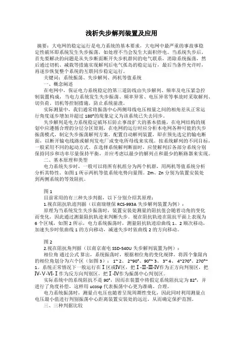
图1目前常用的有三种失步判据,以下分别介绍其原理:1.视在阻抗轨迹判据(以南瑞继保RCS-993A失步解列装置为例):原理为当系统发生失步振荡时,装置安装处测量的阻抗值会随着功角的变化而变化,因此通过测量阻抗轨迹来判断失步。
视在阻抗轨迹在阻抗平面上表现为6个区域,如图2所示,电力系统振荡时,测量阻抗轨迹沿曲线1、2顺次移动,加速失步时依曲线1的方向移动,减速失步时依曲线2的方向移动。

1Safety Instructions• FAILURE to use this device according toinstructions may cause serious injury.• NEVER attempt to transfer a patient or residentwhose weight exceeds the indicated maximumcapacity for this device or any accessory.• NEVER leave a patient unattended during transfer• DO NOT use without complete understanding ofsafe and correct operation• DO NOT use for the purpose of transportation overlong distances.• DO NOT use for the purpose of seating over longextended periods of time..3Product Features DESCRIPTION & APPLICATIONSThe Span F450T is a device from Span-America that represents a class of medical devices collectively referred to as standing transfer aids. The Span standing transfer aid is positioned between a traditional walkeror wheelchair and the common electric stand assist patient lift. TheF450T is a transfer assist unit which keeps the user actively engaged in the process. Transfer functions of all types are quick and require minimal caregiver assistance. Each unit is equipped with a crossbar where users can grasp and pull their self up into a standing position using their own strength. The padded split seats swing out allowing the user to stand place to form a secure and comfortable seat for the user to sit on for the remainder of the transfer.A patient or resident who qualifies to use the lift must have enoughleg and lower body strength to stand up and remain in the standing/ sitting position. Adequate arm strength is required if the patient must use present a potential for falling down will find the F450T a useful and safe transfer device. For patients who lack these requirements, a sit-to-stand lift such as the electric powered Span patient lift is preferred and recommended.The Span F450T standing transfer aid is suitable for the following types of transfers:• Bed to Chair/Wheelchair• Bed/Chair/Wheelchair to commode• Room to Room4235SPAN F450TMaximum CapacityMinimum Base Width Closed Base Width Base Height Unit Weight Maximum Base Width Base opens Minimum Seat Height Knee Pads / Shin Guards Optional Seat Locks Open Base Width Overall Height Overall Length Seat Width Optional Support Strap *Measured to the outside of each base leg with the base legs in the widest open position **Measured from the ground to the bottom of the seatUpgrade Base to 450 Lb 450 Lb / 205 Kg 26.826.7”4.5”71 Lb37”*Yes26.7”**YesYes37”*43.3”35.4”20”YesN/ASpecifications & Options4Assembly6Prior to assembly, unpack all parts from the shipping carton and check for any missing parts. Contact your dealer immediately if a part is missing.Factory assembled base with foot plate and castorsParts List1.Cross Bar x 22.Right Side Arm 3.Left Side Arm 4.Side Support Arm x 25.Knee Pad Support Bar 6.Knee Pad x 27.Seat x 2Tools & FastenersA18x Carriage bolt A22x Hex bolt A34x Hex screw A410x Washer A510x Lock washer A68x Lock nut A72x Plastic cap T11x Wrench T21x Allen keyease of assembly.Insert the kneepads into the support bar andsecure them in place with bolts and washers(A2 +A5 +A4) as indicated below.Cover the two bolt heads with black plasticcaps (A7) to complete kneepad assembly. Install the kneepad assembly between the twoside support arms as shown. Fasten in placewith four carriage bolts, nuts and washers.854Use the 4 hex screws (A3)Allen key (T2) to tightenthe completed assemblyInsert the two cross bars into the holes on the seat and handle bar support units.holes in the support units.Insert the kneepad side support assemblyinto the base slots and then insert the seatassembly into the kneepad and sidesupport assembly.Optional Seat Lock8Operating InstructionsMaintenance & Inspection • The Span F450T Standing Transfer Aid is a manual unit and therefore requires minimal maintenance on an ongoing basis. However to insure safety and proper use the following steps should be taken on a monthly basis.• Check all bolt/nut assemblies to make sure they are tight and no wear and tear is evident. Replace and tighten any worn assemblies prior to using the F450T.• Check the two seat assemblies to make sure they are not worn or damaged and that the bolts are tight. Replace any worn or damaged seat components before using the F450T.• Check the casters to make sure they are in working order and are secured firmly to the F450T. Replace any worn or damaged casters prior to using the F450T.1311WARRANTY POLICYSpan-America (“Span”) off ers a limited warranty on all patient lifts, slings and accessories to be free of defects in workmanship and product performance. This warranty extends only to the original purchaser and is non-transferrable. All warranty claims must be submitted by the authorized dealer or distributor who originally sold the product with proper proof of sale and serial number where applicable. Prior Return Authorization (RA) from Span is required for all warranty replacements. Span reserves the right to repair or replace only defective parts or accessories in lieu of a complete new patient lift. The repaired or replacement part shall be warranted for a period equal to the remainder of the warranty period of the defective part.Span does not provide advance replacements for warranty claims. For situations where an end user requires a replacement in advance and before a warranty item can be returned, dealer or distributor must purchase the replacement at full cost. All freight charges for the replacement are the sole responsibility of the dealer or distributor. When end user returns warranty item and item proves to be defective, Span will issue full credit for the replacement less freight charges.Product returned without RA number clearly marked on the package or product returned later than 30 days after authorization will be refused and returned at sender’s expense. Final disposition of warranty claims will be determined at the sole discretion of Span. Warranty claims will be denied for any of the following: product abuse or misuse, accidental or malicious damage, improper installation, product used with parts, components or accessories with quality or specifi cations incompatible with product, adulterated product, user neglect, failure to maintain and service product as specifi ed in the owner’s manual or care tag, serial number removed or defaced, or normal wear and tear.Span warrants the following products and components beginning from the purchase invoice date for the specifi ed time period: WARRANTY PERIOD PRODUCT OR COMPONENTThree (3) Years Patient lift frame or spreader barTwo (2) Years Actuator, control box, pendant, charger, weigh scale, Stand Aids, or casters excluding normal tread wearOne (1) Year Battery or hydraulic pumpSix (6) Months Reusable fabric slingsSingle Patient Specifi c slings are designed for limited use with one patient and may not be laundered. Span will replace any disposable sling found to have a manufacturing defect. Normal wear and tear will not be covered under warranty.This warranty expressly excludes wearable components including but not limited to foam parts and caster tread. Furthermore, this warranty is void and null for product that has not been purchased or paid for in full.RETURN GOODS POLICYPatient lifts may not be returned unless the wrong lift is shipped in error by Span or the lift is heavily damaged or defective out of the box. For all other items, purchaser may request a RA for purchased goods within thirty (30) days of purchase invoice date. All returns must be received by Span no later than thirty (30) days after authorization or the RA will be voided. Return package must be clearly marked with the RA number or the package may be refused and returned at sender’s expense. Patient lifts are subject to a minimum restocking fee of 25% or more. Please note that patient lifts being returned must be in the original carton with all parts, components and packing materials included. Failure to comply with this requirement will incur higher restocking fees or a rejection of the return. Slings, parts and accessories may only be returned if they have not been used. There are no exceptions to this provision.All freight charges are the sole responsibility of purchaser when any of the following occurs: (i) ordering error where an incorrect item is shipped in accordance with purchase order, (ii) an order is cancelled while in transit or (iii) delivery is refused by customer. Span reserves the right to issue credit amounts based on strict adherence to this policy.13。

![SSD540C通信码表V3[1][1][1].04](https://uimg.taocdn.com/83bc5f194431b90d6c85c7aa.webp)
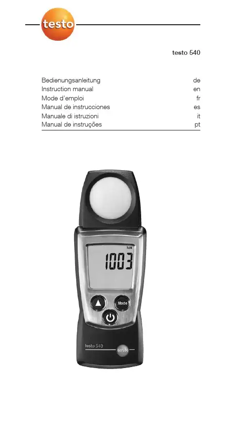
testo 540 Bedienungsanleitung de Instruction manual en Mode d’emploi fr Manual de instrucciones es Manuale di istruzioni it Manual de instruções ptShort manual testo 54011Short manual testo 540Protection cap: Park positionLight sensorDisplayControl keysBattery compartment (on rear)Basic settingsInstrument off > press and hold 2s > select withconfirm with ():Auto off function: OFF, ONSwitching the instrument onPress .Switching the display light on (for 10s)Instrument on > pressSelect display sizeInstrument on > select with :lux, ftcSelect display modeInstrument on > select with :Current reading > Hold: Readings are held > Max: Maximum values > Min: Minimum valuesSwitching the instrument off:Instrument on >press and hold 2s.en12Safety and the environmentSafety and the environment About this documenti Please read this documentation through carefully andfamiliarise yourself with the product before putting it to use.Keep this document to hand so that you can refer to it whennecessary. Hand this documentation on to any subsequentusers of the product.i Pay particular attention to information emphasised by thefollowing symbols:Important.Avoid personal injury/damage to equipmenti Only operate the measuring instrument properly, for itsintended purpose and within the parameters specified in thetechnical data. Do not use force.i Never store the product together with solvents, acids or otheraggressive substances.i Only carry out the maintenance and repair work that isdescribed in the documentation. Follow the prescribed stepswhen doing so. Use only OEM spare parts from Testo.Protecting the environmenti Take faulty rechargeable batteries as well as spent batteries tothe collection points provided for them.i Send the product back to Testo at the end of its useful life. Wewill ensure that it is disposed of in an environmentally friendlymanner.Specifications13 SpecificationsFunctions and useThe testo 540 is an illuminance measuring instrument. It is normally used to measure illuminance, e.g. at workplaces. Technical dataMeasurement data·Sensor:Photo diode·Parameters:Lux (lm/m2), foot candle (lm/ft2) ·Measuring ranges:0...99999 Lux, 0...93000 ftc ·Resolutions:1 Lux (0...19,999 Lux), 10 Lux (rest of range)0.1 ftc (0...1,858.0 Lux), 1 ftc (rest of range)·Accuracies (Nominal temperature 25°C, ±1 Digit):± 3 % to reference (Class B, DIN5032 part7)·Measuring rate:0.5 s Further instrument data·Protection class: IP40·Ambient conditions:0...50 °C, 32...122 °F·Storage/transport conditions:-40...70 °C, -40...158 °F ·Voltage supply:2x 1.5 V type AAA·Battery life:200 h (without display light)·Dimensions:133x46x25mm / 5.2x1.8x1.0 in (inc. protection cap)·Weight: 95 g / 3.4 oz (inc. batteries and protection cap)Directives,standards and tests·EC Directive:2004/108/EEC Warranty·Duration: 2 years·Warranty conditions: see guarantee cardProduct description14Product descriptionAt a glanceProtection cap: Park positionLight sensorDisplayControl keysBattery compartment (on rear)First steps²Inserting batteries:1To open the battery compartment, push the battery cover down.2Insert batteries (2x 1.5 V type AAA). Observe the polarity!3To close the battery compartment, push the battery cover back on.²Basic settings (configuration mode):Adjustable functions·Auto off function: OFF, ON(instrument switches off automatically if no key ispressed for 10 minutes)1until and appear on the display (configuration mode).-The adjustable function is displayed. The current setting flashes.23Press () to confirm the input.-The instrument changes to measuring mode.Using the product15 Using the productTo guarantee correct readings: Hold the instrument horizontally so that the light sensor is directed upwards.²Switching the instrument on:i Press .-Measuring mode is opened.²Switching the display light on:The instrument is switched on.i Press .-The display light goes out automatically if no key ispressed for 10 seconds.²Changing the parameter unit:i Press until the desired unit appears.Adjustable units·lux·ftc²Changing the display view:Adjustable views·Current reading·Hold: Readings are held.·Max: Maximum values since the instrument was last switched on or last reset.·Min: Minimum values since the instrument was last switched on or last reset.i Press several times until the desired view appears.²Resetting Max/Min values:1Press several times until the desired view appears.2Press and hold until ----appears.3Repeat steps 1and 2for all values that are to be reset.²Switching the instrument off:i Press and hold until the display goes out.16Maintaining the productMaintaining the product±Changing batteries:1To open the battery compartment, push the battery cover down.2Remove used batteries and insert new batteries(2x 1.5 V type AAA). Observe the polarity!3To close the battery compartment, push the battery cover back on.±Cleaning the housing:i Clean the housing with a moist cloth (soap suds) if it is dirty.Do not use aggressive cleaning agents or solvents!Tips and assistance17 Tips and assistanceQuestions and answersQuestion Possible causes/solutionsHi·Readings outside the measuring range (too high:Keep to the permitted measuring range.·Residual capacity <10 min: Change batteries.If we could not answer your question, please contact your dealeror Testo Customer Service. Contact details can be found on the guarantee card or on the Internet at: 18Notestesto AGPostfach 1140, 79849 Lenzkirch Testo-Straße 1, 79853 Lenzkirch Telefon: (07653) 681-0Fax: (07653) 681-100E-Mail:*************Internet: 0973.5400/03/Sh/dr/07.08.2008w w w .t e s t o .c o m。
![ZXUPS_T520&T530&T540&T560&T580(V2.0)不间断电源用户手册[1]](https://uimg.taocdn.com/70c712d5360cba1aa811dab2.webp)

由巴西3.21大停电谈电力系统稳定控制整体解决方案事故原因为:定值误整定造成断路器过负荷跳闸,引起交流母线失压,进而造成美一直流双极停运,在交流母线失压情况下,稳控装置认为切机信号无效,美丽山水电站机组因自身保护而切除。
事故造成北部和东北部电网解列,南部、东南部以及中西部电网因低频策略动作而切负荷。
最终损失负荷是事故前美一直流输送功率的5倍。
此次事故启示我们:(1)重视稳控系统、低频低压减载、高周切机、振荡解列方案的研究和三道防线的建设;(2)研究在线实时稳定控制系统,解决稳控策略失配问题。
2 稳定控制技术的现状电力系统稳定控制是指为防止电力系统由于扰动而发生稳定破坏、运行参数严重超出规定范围,以及事故进一步扩大引起大范围停电而进行的紧急控制,构成了电力系统的第二道防线和第三道防线。
电力系统稳定控制的类型包括暂态稳定控制、动态稳定控制、电压稳定控制、频率稳定控制和过负荷控制。
根据策略实现方式采取技术路线的不同,稳定控制系统分为如下三类:(1)技术人员采用离线仿真软件工具(如BPA、PSASP等)开展大量的仿真计算,通过分析、归纳、总结,形成包含运行方式、故障元件、故障类型、稳定控制措施、定值等关键字段的策略表,交由稳控装置设备厂家开发人员编程(或配置)实现。
实际运行时,通过判断运行方式、故障元件和类型,实时匹配离线策略表,找到相应的控制措施,并动作出口。
基于离线策略表的稳定控制系统已得到了大量应用,技术最成熟,是目前的主流实现方式。
但这类稳定控制系统存在离线工作量大,控制措施的过量或欠量受策略制定技术人员的经验和性格影响,在实际运行中存在策略失配的问题。
(2)基于在线预决策的稳定控制系统:在线预决策系统定周期(典型时间取5分钟)地从数据采集与监控系统(SCADA)获得电网运行状态数据,基于预想故障集,开展在当前运行方式下的稳定性评估,对于失稳的情形,搜索控制措施集,形成稳控策略表,刷新现场稳控装置中存储的策略表或定值。
Dell Studio™ 540 服务手册注、注意和警告本说明文件中的信息如有更改,恕不另行通知。
2008 Dell Inc. 版权所有,翻印必究。
未经 Dell Inc. 书面许可,严禁以任何形式复制这些材料。
本文中使用的商标:Dell 、DELL 徽标和 Dell Studio 是 Dell Inc. 的商标;Microsoft 、Windows 是 Microsoft Corporation 在美国和/或其他国家和地区的商标或注册商标。
本说明文件中述及的其它商标和商品名称是指拥有相应标记和名称的公司或其制造的产品。
Dell Inc. 对其它公司的商标和产品名称不拥有任何所有权。
型号:DCMA2008 年 7 月 修订版 A00技术概览开始之前装回主机盖装回前面板装回内存模块更换 PCI/PCI Express 卡更换驱动器更换风扇更换前 I/O 面板 更换处理器 装回系统板 更换电源设备 更换电池 更换橡皮脚垫 系统设置程序注: "注"表示可以帮助您更好地使用计算机的重要信息。
注意: "注意"表示可能会损坏硬件或导致数据丢失,并告诉您如何避免此类问题。
警告: "警告"表示可能会造成财产损失、人身伤害甚至死亡。
返回目录页面开始之前Dell™ Studio 540 服务手册技术规格建议使用的工具关闭计算机安全说明本章介绍了卸下和安装计算机中组件的步骤。
除非另有说明,否则将认为在执行每个步骤时均满足下列条件:l 您已经执行了关闭计算机和安全说明中的步骤。
l您已经阅读了计算机附带的安全信息。
l 可以通过以相反顺序执行拆卸步骤来装回组件或安装单独购买的组件。
技术规格有关计算机技术规格的信息,请参阅计算机随附的《安装指南》或参阅 Dell 支持 Web 站点: 。
建议使用的工具执行本说明文件中的步骤可能需要使用小型 2 号梅花槽螺丝刀。
关闭计算机1.关闭操作系统。
Version7.0Copyright2022Hillstone Networks.All rights reserved.Information in this document is subject to change without notice.The software described in this document is fur-nished under a license agreement or nondisclosure agreement.The software may be used or copied only in accord-ance with the terms of those agreements.No part of this publication may be reproduced,stored in a retrieval system,or transmitted in any form or any means electronic or mechanical,including photocopying and recording for any purpose other than the purchaser's personal use without the written permission of Hillstone Networks. Hillstone Networks本文档禁止用于任何商业用途。
关于本手册本手册为硬件参考指南,帮助用户正确安装山石网科的设备。
获得更多的文档资料,请访问:https://针对本文档的反馈,请发送邮件到:*************************联系信息北京苏州地址:北京市海淀区宝盛南路1号院20号楼5层地址:苏州市高新区科技城景润路181号邮编:100192邮编:215000联系我们:https:///about/contact_Hillstone.html山石网科https://TWNO:TW-HW-ADC-CN-V7.0-8/23/2022目录目录1产品中有毒有害物质或元素的名称及含量1前言1内容简介1手册约定1第1章产品介绍2主机硬件介绍2前面板介绍2后面板介绍6指示灯8系统参数11扩展模块18扩展模块指示灯含义20接口扩展模块的配置与使用22查看扩展模块的信息23扩展槽23端口属性24配置口(CON口)24USB接口24千兆电口24SFP接口25 SFP+接口26 QSFP+接口27 QSFP+接口的拆分28切换光接口工作模式28光接口的光转电29光模块29 1GE(SFP)光模块30 1GE(SFP)光模块适配情况31千兆光电模块33光电模块适配情况33 10GE(SFP+)光模块33 10GE(SFP+)光模块适配情况35 40GE(QSFP+)光模块37 40GE(QSFP+)光模块适配情况38设备适配光模块情况39查看光模块信息40 CLR按键41电源42电源模块43硬盘46国家商用密码算法加密卡46第2章设备安装前的准备工作47介绍47安装场所要求47温度/湿度要求47洁净度要求48防静电要求49电磁环境要求49接地要求49检查安装台49机柜要求50机柜尺寸和间距50机柜通风要求50机架要求50机架尺寸和承重要求50机架间距要求51机架固定要求51确认收到的物品51安装设备、工具和电缆51其它安全注意事项51第3章设备的安装53常用工具53注意事项53将设备安装在工作台上53将设备安装到标准机架中54使用托盘安装54使用导轨安装56线缆连接59连接地线59连接配置电缆60连接以太网线缆60连接以太网电口线缆61连接以太网光口线缆61连接交流电源线62连接直流电源线62安装完成后的检查64第4章设备的启动和配置65介绍65搭建配置环境65搭建配置口(CON口)的配置环境65搭建WebUI配置环境66连通网络67使用单臂模式连通网络67步骤一:配置接口。
本文档包含有关安装 Sun Fire X4540 服务器的基本信息。
有关详细的安装信息,请参见可订阅的文档《Sun Fire X4500/X4540 服务器安装指南》(820-5997)。
有关其他的 Sun Fire X4540 服务器文档,可以在以下网址获取:/app/docs/prod/sf.x4540安全标准和规范信息安装 Sun Fire X4540 服务器之前,请先参阅安全标准和规范指南以及《Sun 硬件系统重要安全信息》(包含在包装箱中)。
连接电缆从包装箱中取出系统并将其安装在机架上之后,请将各种电缆连接到 Sun Fire X4540 服务器上可用的输入/输出(I/O) 端口。
根据需要,将线缆连接到服务器背面板上的相应连接器。
参见图1。
图 1 Sun Fire X4540 服务器背面板注 – 将采用新型 PSU 盖板。
盖板打开和关闭服务器电源此服务器有两种级别的电源:备用电源和主电源。
要对服务处理器 (SP) 进行初始配置,需要使用备用电源。
此外,本节还介绍了打开和关闭主电源模式的过程。
提供备用电源以便进行服务处理器 (SP) 的初始配置进行 SP 初始配置之前,请执行本过程以便为 SP 接通备用电源。
注意 – 必须先安装好所有风扇、组件散热器、空气挡板以及各个盖板,然后才能运行服务器。
如果没有安装好适当的冷却装置而操作服务器,则可能对服务器组件造成严重损害。
1.将接地型交流 (AC) 电源线插入服务器背面板上的两个交流电源连接器,以及接地型交流(200 V AC 至 240 V AC)电源插座。
注 – 本系统适合使用 220 VAC 电压。
可以选择使用第三个 PSU 在 110 VAC 电压下操作。
按照第 3 页中的“连接到 ILOM 服务处理器”中的描述,继续执行初始软件设置任务。
▼打开主电源模式1.确认已连接好电源线且已打开备用电源。
在备用电源模式下,前面板中的电源/正常 LED 指示灯将闪烁。
S S D场强仪使用说明书 The document was prepared on January 2, 2021目录8. 技术指标 (8)A 场强仪概述17S5200/17S5200D场强仪是一款用于模拟电视/数字电视建设和维护,测量电视信号电平和功率电平的仪器,在CATV 系统日常维护中有广泛应用。
兼容模拟/数字频道,综合性能强;采用高亮度背光工作模式,液晶显示清晰明了,双频道测量显示,方便实用;设置数字键盘输入,应用操作简单;本仪器是一个体积小、重量轻便携式信号电平测量仪器,方便在不同的工作坏境下测试。
B 仪器功能特点1、适用于CATV 系统维护测试的仪器2、体积小、重量轻,方便携带3、采用大容量锂电池,使用时间长4、双频道测量显示,方便实用5、C/N、V/A、斜率、干线电压测量C 注意事项1. 仪器使用电池为800mAh 锂电池,请在首次使用前,对电池进行充电,充电时间应不小于2 小时。
2. 对本机电池进行充电,请使用本公司提供的充电器,否则,有可能造成用户不必要的损失。
3. 仪器请勿在强电磁场环境中工作,否则会造成测量数值不准确。
4. 仪器的RF 输入插座,最大输入电压(交流或直流)应不大于100V,否则会造成仪器的损坏。
5. 仪器设有自动关机功能,如果三分钟无任何按键操作将自动关闭电源。
D 面板及液晶显示器RF 输入插座液晶显示屏操作键盘充电插座E 按键说明单频道测量键单频率测量键双频道同屏显示/斜率测量键载噪比测量键干线电压及电池电压测量键、液晶背光开启键选定的频道数增加键选定的频道数减少键扬声器开启/关闭键频道输入切换、小数点输入键~ 数字1~9 输入键电源开关键数字/模拟频道切换、数字0输入键输入确认键1. 单频道测量按下键,仪器进入单频道测量模式,液晶显示界面如下:此时,屏幕左下方显示当前频道的频道号,右下方显示当前频道的图像载波频率值,屏幕左方显示当前频道的V/A 值(图像载波电平与伴音载波电平差),右方显示当前频道的图像载波电平。
USR-N540产品使用说明手册工业级串口服务器联网找有人可信赖的智慧工业物联网伙伴产品使用说明手册USR-N540USR-N540产品使用说明手册目录Content 一、基本测试案例 (3)1.1 结构框图and数据流向 (3)1.2 资料下载 (3)1.3 测试环境 (3)1.4 拨码开关 (4)1.5 DB9转接板使用介绍 (4)1.6 DB9引脚定义 (5)1.7 指示灯状态 (5)1.8 恢复出厂设置方式 (6)1.9 测试步骤 (6)1.9.1. 硬件连接 (6)1.10 参数设置 (6)1.10.1. 数据通信测试 (12)1.11 基本测试常见问题 (14)二、常见用法 (15)三、常见问题排查方法 (15)3.1 串口无法传输数据 (15)3.2 网络连接异常 (15)3.3 无法建立TCP连接 (15)3.4 透传数据格式不对 (15)3.5 MODBUS网关无法读取数据 (15)3.6 连接云平台设置问题 (16)四、更新历史 (17)五、联系方式 (18)一、基本测试案例1.1结构框图and数据流向1.2资料下载联系技术索取相关资料。
1.3测试环境如果您已经购买USR-N540(H7),会有如下配件:所需物品:R-N540-H7一台2.DC5V 1A或DC12V 1A电源一个3.232转USB串口线*1或485转USB串口线*1(需要自备)4.网线一根5.电脑一台注:DB9-M转RJ45转接头发货时默认只配一个,需要多个,需单独购买232转USB串口线购买链接:https:///item.htm?id=542589831435&spm=2014.21600712.0.0 485转USB购买链接:/peijian/usb-rs485.html转接头购买链接:/peijian/RJ45zhuanjiexian.html系统说明:当前使用的是windows 10系统,软件兼容windows 7、windows 8、windows Vistal1.4拨码开关1.5DB9转接板使用介绍为方便用户使用接线端子接线,N540为用户配置串口转接板,串口转接板为工业级接口,更适合工业场合使用。