海尔洗衣机 全系列产品培训
- 格式:ppt
- 大小:1.26 MB
- 文档页数:28
一、双桶洗衣机培训资料(一)洗衣机的产生及进展第一台洗衣机产生于十九世纪末的欧洲,是一台木质的人力驱动洗衣机,随着现代工业的高速进展,洗衣机的制造技术也发生了革命性的变化,先后显现了美洲的搅拌式洗衣机、欧洲的滚筒式洗衣机和亚洲的波轮式洗衣机,洗衣机制造技术在全球迅速普及,到二十世纪末全球洗衣机年销量超过5000万台。
中国的洗衣机生产开始于70年代,最早生产单桶洗衣机,进入80年代后,开始引进日本技术生产双桶洗衣机,80年代后期机械程控器操纵的套桶全自动洗衣机显现了,90年代初,电脑操纵的套桶全自动洗衣机逐步走向市场,同期开始引进欧洲技术在国内生产滚筒洗衣机。
到90年代末,我国洗衣机年销量已超过1000万台,成为世界上最大的洗衣机生产国。
(二)洗衣机的差不多概念和术语1)几个差不多概念I、家用电动洗衣机利用电能驱动,依靠机械作用洗涤衣物的器具。
II、波轮式洗衣机被洗涤物浸没于洗涤水中,依靠波轮连续转动或波轮正反转动的方式进行洗涤的洗衣机。
波轮洗涤时转动时刻大于等于15秒,停止时刻为5秒的称涡卷式;转动时刻小于15秒,停止时刻小于5秒的称为新水流式。
III、滚筒式洗衣机被洗涤物放在滚筒内,部分浸在水中,依靠滚筒连续转动或定时正反向转动的方式进行洗涤的洗衣机。
IV、搅拌式洗衣机被洗涤物浸没于洗涤水中,依靠搅拌叶往复运动的方式进行洗涤的洗衣机。
V、一般洗衣机洗涤、漂洗、脱水各功能的动作需要手工转换的洗衣机。
VI、半自动洗衣机在洗涤、漂洗、脱水各功能之间,其中任意两个功能转换不用手工操作而能自动进行的洗衣机。
VII、全自动洗衣机同时具有洗涤、漂洗、脱水各功能,它们之间的转换不用手工操作而能自动进行的洗衣机。
VIII、额定洗涤容量一次可洗干燥状态标准洗涤物的最大质量,以千克为单位。
IX、额定脱水容量一次可脱水干燥状态标准洗涤物的最大质量,以千克为单位。
2)波轮式洗衣机的几个重要指标I、洗净比被测样机洗净率与参比样机洗净率之比。


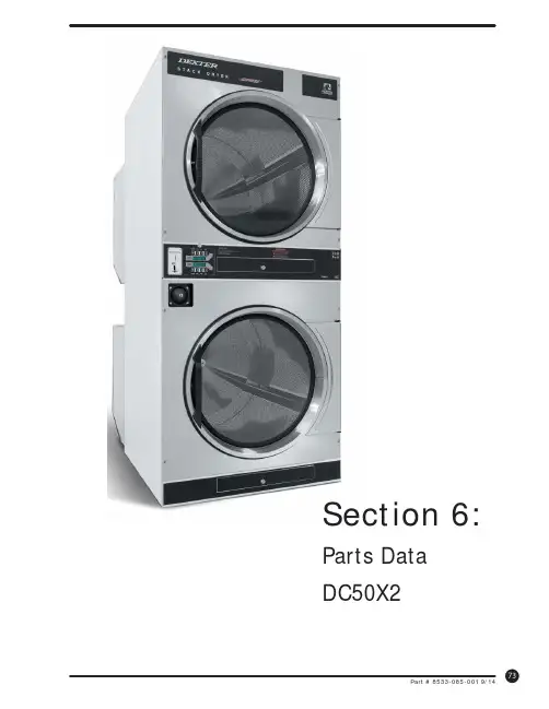
Section 6: Parts DataDC50X264310131211216547Cabinet GroupKey Part Number Description Quantity * 9960-285-008Door Assy., Loading Complete-Wht (2)* 9960-285-011Door Assy., Loading Complete-SS (2)* 9960-285-007Door Assy., Loading Complete-Chrome/BLK/SS (2)1 9960-284-002Door Assy., Loading-SS(ring only) (2)1 9960-284-004Door Assy., Loading-Chrome(ring only) (2)2 9982-353-002Plate Assy., Hinge (Wht) No Pin (2)2 9982-353-001Plate Assy., Hinge (SS) No Pin (2)* 9545-012-015Screw, Hinge to Door (8)* 8640-413-002Nut, Hinge to Door (8)3 9212-002-004Glass, Door (2)4 9206-413-002Gasket, Glass Black (2)* 9548-117-000Support, Door Glass (2)5 9206-420-005Gasket, Outer Rim Black (2)6 9244-082-001Handle, Loading Door (2)* 9545-018-017Screw, Handle 1/4-20 x 3/8 (4)* 9531-033-003Stud, Door Catch (2)* 8640-413-001Nut, Hex (2)* 8640-413-003Nut, Acorn (2)* 9086-015-002Catch, Loading Door (2)* 8638-190-009Pop Rivet for mtg. catch (4)* 8641-582-006Lockwasher (4)* 8640-399-001Spring Nut (6)7 9989-521-003Panel Assy., Front- Lower (Wht) (1)7 9989-521-001Panel Assy., Front- Lower (SS) (1)8 9989-517-003Panel Assy., Front- Upper (Wht) (1)8 9989-517-001Panel Assy., Front- Upper (SS) (1)* 9277-054-001Insulation Front Panel, half moon (top) (2)* 9277-054-002Insulation Front Panel, half moon (bottom) (2)9 9545-008-014Screw, FLHDCR, 10B x 1 (14) (6)* 8641-585-001 Lockwasher* 8640-399-001Nut, Spring (12)10 9544-069-002Strap, Hinge (Wht) (2)10 9544-069-005Strap, Hinge (SS/Black) (2)* 9545-012-028Screw, Hinge to Panel (8)11 9545-052-001Screw, Door to Hinge Strap (Special Black Type) (2)12 8641-436-003Washer, Fiber (2)13 9021-041-001Acceptor, Coin (1)* 9486-149-001Retainer, Coin Acceptor (2)14 9545-053-002Screw (4)* 9801-099-001Switch, Optical (1)Cabinet Group ContinuedKey Part Number Description Quantity15 9994-032-001Escutcheon, Upper (1)16 9435-039-002Trim, Overlay-Upper Blue (1)16 9435-039-001 Trim, Overlay-Upper Black (1)17 9994-033-001Escutcheon, Lower (1)18 9435-023-001Trim, Overlay-Lower Blue (1)18 9435-031-001Trim, Overlay-Lower Black (1)* 9545-020-009Screw (20)19 9412-167-002Nameplate Stack Dryer Express Blue (1)19 9412-167-001Nameplate Stack Dryer Express Black (1)20 9866-005-001Lint Drawer Assembly Blue (2)20 9866-005-004Lint Drawer Assembly Black (2)21 9435-024-001Overlay Trim, Lint Drwr-Blue (1)21 9435-032-001Overlay Trim, Lint Drwr-Black (1)* 9532-074-003Felt Seal ( back of lint screen assembly ) (2)* 9805-033-002Lint Screen Assembly ONLY (no front) (2)* 9555-057-008Replaceable Lint Screen Only (2)22 8650-012-004Lock and Key, Lint Drawer (2)* 6292-006-010Key 6101 only (2)* 9095-043-001Cam, Lock (2)* 9545-008-001Lint Screen Strap Hold Down Screws 10Bx 1/4 (32)23 9857-198-001Controls Assy, Blue (1)23 9857-198-003Controls Assy, Black (1)* 9627-869-001Harness, Electronic Control (1)24 8650-012-003Lock and Key, Control (1)* 9095-041-001Cam, Lock (1)* 6292-006-007Key only 6324 (1)* 9627-855-003Harness, Heat Sensor (1)* 8640-276-002Wire Nut Connector Grey (4)25 9501-004-003Sensor Temp Control (2)26 9501-008-001Bracket for Heat Sensor Mounting (Under Basket) w/ sensor..2* 9545-045-005Screw, Round Head (Mounts sensor; phillips head) (2)* 9209-037-002Gromm.et, 3/16 ID (2)* 8544-006-001Leg, Leveling 1/2” (4)* 9074-320-001 Cover, Cabinet (Top) (1)* 9277-041-017 Insulation Cabinet Cover (1)* 9732-276-001Kit for Dryers without Neutral and using 208-240 volt (1)* 9732-102-013LP Kit for 50Lb Stk Dryers (1)* 9732-243-001Stack Dryer Trunion Puller (1)* 9544-041-002 Strap - Bead Tie (1)27 9942-038-005 Vault, Coin Box (1)* 9545-008-024 Screws, Mounting-Coin Vault (2)28 9897-099-002 Coin Box Assy, Large Blue (1)28 9807-099-004 Coin Box Assy, Large Black (1)191526252792531089Control Parts GroupKey Part Number Description Quantity * 9857-198-001Controls Assy, Electronic Mounted With Membrane Switch, BLU (1)* 9857-198-003Controls Assy, Electronic Mounted With Membrane Switch, BLK (1)1 9826-008-001 Trough Assembly (1)2 9032-062-002 Button-Push, Control, Blue (2)2 9032-062-001 Button-Push, Control, Black (2)3 9538-166-011Spacer-Metal, 4mm (4)4 9486-158-001 Retainer-Push Button (2)5 8640-424-002Nut-Hex, Elastic stop, #4-40 (4)6 8652-130-038Terminal-Grounding clip (1)7 9534-365-001Spring-Flat, Control (1)8 9545-008-001Screw-Hex, #10B x 1/4 (2)9 9545-044-010 Screw-Hex, #10B x 1/4 (10)9 8641-582-005Washer-External tooth, #6 (10)10 9435-038-001Overlay-Control, Coin, Black (1)10 9435-038-002Overlay-Control, Coin, Blue (1)11 9021-041-001Acceptor-Coin, Optical (1)* 9486-149-001Retainer, Coin Acceptor (1)12 9545-053-002Screw (4)* 9801-099-001 Optical Sensor, Replacement (1)Note: Jumpers required if using 1.5 Control on Older Machines (P9 Connection)* 8220-155-001 Wire Assy, Jumper, 30Lb Stack Coin (1)* 8220-155-002 Wire Assy, Jumper, 50Lb Stack Coin (1)Door Switch GroupPart NumberDescription Quantity9539-487-001Door Switches (2)Hinge Plate Cover1 9074-340-002 Cover-Hinge, Black .....................................................................22 8636-008-010 Screw-TRHDCR, 10B x 3/8, Black.. (4)12Bearing Housing GroupKey Part Number Description Quantity J1 9241-189-002 Housing, Bearing (2)J2 9036-159-003Bearing, Ball Rear..................................................................... .2 * 9538-183-001 Spacer, Bearing (2)* 9036-159-001Bearing, Ball Front .................................................................... .2 J5 9545-017-017Bolt, 1/2 x 3/4 . (8)J7 8640-417-002Nut, 1/2 (8)* 9803-201-001Bearing Housing Complete Ass’y (includes bearings,spacer) (2)J4 9545-017-018Screw 1/2 x 1 1/2 (4)Burner Housing GroupKey Part Number Description Quantity * 9803-207-001 Housing Assembly, Burner (2)1a 9452-730-001Service Burner Plate Front... (2)1 9452-729-001 Service Plate baffl e Recirculation Chamber Clean Out (2)* 9545-008-006Screws (8)2 9545-008-001Screw (16)18 9003-220-001Angle, Burner Support (2)* 9545-008-006Screw (4)17 9048-020-002Burner, Main (4)* 9545-008-006Screw 10AB x 3/8” (4)* 9454-824-001 Panel, Back Burner Housing (2)4 9545-008-001Screw 10B x1/4” (8)5 9875-002-003Electrode Assy, Ignition (2)19 9545-045-001Screw, Electrode Mtg 8B x 1/4” (4)7 9379-186-001Valve, Gas Shut Off (1)8 9857-134-001Control Assy, Gas (2)9 9381-012-001Manifold, Assy (2)* 9425-069-021Orifi ce, Burner-Natural #27 (4)* 9425-069-022Orifi ce, Burner-LP #44 (4)10 9029-175-001Bracket, Manifold (2)22 8615-104-038Pipe Plug in end of Burner Manifold (2)* 9545-008-006Screw (4)12 9576-203-002Thermostat, Hi-Limit (2)* 9538-142-001Spacer, Hi-Limit (4)* 9545-045-007 Screw 8B x 3/4” (4)13 9074-329-001Cover, Hi-Limit Stat Ignitor (2)* 9545-008-006Screw (6)* 9576-207-008Thermostat, Safety Shutoff (2)* 9545-008-006Screw (4)15 9825-062-001Cover, Safety Stat (2)* 9545-008-024Screw (6)16 9857-116-003Control, Ignition Fenwall (3 trybox) (2)* 9732-102-013Kit, LP Conversion 50Lb Stack Kit (2)* 9838-018-003Welded One Piece Gas Pipe Assembly (1)Part # 8533-085-001 9/14Burner Housing Group Photos10221092221851A141594851613Rear ViewKey Part Number Description Quantity * 9627-861-001Wire Harness Overtemperature Switch/Air Switch (2)* 9801-098-001Switch Assy, Air Flow (2)1 9539-461-009Switch, Air Flow (2)2 9029-200-001 Bracket, Switch- Air Flow (2)3 9008-007-001Actuator, Switch (2)4 9451-169-002Pin, Cotter (2)5 9545-020-001Screw 4-40 x 5/8” (4)* 8640-401-001Nut, Special Twin .#4-40 (2)* 9550-169-003Shield, Switch (2)6 9376-322-001Motor, Drive (2)7 9452-770-001Plate, Motor Mounting (1)* 9545-029-008Bolt 3/8” - 16 x 3/4” (8)* 8641-582-003Lockwash Spring 3/8 (8)8 9545-018-019Screw, Motor Plate to Back Assy. 1/4-20x 2 1/2 (8)* 8641-582-007Lockwasher 1/4 (8)9 9538-163-006Spacr (8)* 8641-581-017Flat Washer 1/4 x 7/8 (24)* 9209-086-002Rubber Grommet (8)* 9538-166-006Grommet Spacers (8)* 9545-028-013Screw, Set (4)10 9962-018-002Back Assy, Blower Hsg (2)11 9991-053-001Support Assy, Intermed. Pulley (2)12 9545-029-010Bolt, Rd Hd 3/8-16 x 1 1/4 (6)12 8640-415-004Nut Flange Wizlock 3/8” - 16 (6)12 8641-581-035Washer, Flat (6)13 9545-029-003Bolt, 3/8-16 x 1 1/2 (2)14 9861-022-001Arm Assy-Tension, Complete (2)* 9487-200-003Ring-Retaining (6)15 9908-048-003Pulley Assy, Intermediate with bronze fl ange bearing (2)* 9036-145-002Bronze Flange Bearing (4)16 9908-047-002Pulley Driven Tumbler (2)17 9040-076-009Belt, Drive Motor (2)18 9040-073-011Belt, Driven Intermediate to Tumbler (2)19 9534-151-000Spring, Tension (2)20 9099-012-005Chain, Tension (2)21 9248-022-002Hook, Tension (2)* 9451-146-001Pin, Damper Hinge (2)* 9074-334-001 Cover Duct Upper (1)22 9973-032-001 Heat Recirculation Assembly Duct (2)* 9453-169-013Motor Pulley - Driver (1)* 9545-028-013Set Screws (2) (2)* 9278-043-001Impeller23 8641-581-026Washer, Flat 1/2” for Tumbler Pulley (2)24 9545-017-009Bolt, 1/2”-13 x 1 1/4 (2)25 8641-582-016Washer, Star 1/2” for Tumbler Pulley (2)* 9545-008-001Screw 10 Bx 1/4” (6)* 9545-014-004Bolt, 5/16-18 x 5/8” (8) (8)5/16-18* 8640-400-003Nut,* 9538-184-001Spacer, Shaft (2)* 9487-234-005Ring Tolerance (2)* 9125-007-001Damper Inside Duct Exhaust (2)* 9125-007-002Damper Inside Duct Exhaust (1)* 8520-141-000Nut, Spring (4)* 9074-335-001Cover Duct Lower (1)* 9545-008-024Screw 10ABx 3/8” (72)* 9029-173-001Bracket for Wire Harness Under Burner Housing (2)Part # 8533-085-001 9/14Part # 8533-085-001 9/14Rear View Photos1264722Rear Panel & Cover GroupKey Part Number Description Quantity19208-090-001Rear Guard Side Panel 1 (2)4 9545-008-024Screws 10 AB x 3/8 (30)5 8502-649-001Label - Connection Electrical (1)8 9208-089-001Rear Guard Back Panel (2)10 8502-600-001Label Warning & Notice (1)11 8502-645-001Label - Instructions (1)12 9109-113-001Transition Assembly Outlet (1)13 9074-320-001 Top Cover Dryer Panel (1)14 9550-188-001 Top Burner Housing Heat Shield Inlet (1)15 9074-321-001 Top Panel Burner Housing Cover (1)Part # 8533-085-001 9/141851113121514Tumbler GroupKey Part Number Description Quantity 9848-131-001Tumbler Assembly Galvanized w/spider (2)G2 9568-013-001Spider Assembly (2)G3 9497-226-002Rod, Tumbler (6)G4 8640-417-005Nut, 1/2 - 13 (6)G6 8641-590-002Washer, Special (6).............................................................................AR G7 9552-013-000Shim* 9848-130-002Tumbler Assembly Stainless Steel (2)G1 9848-130-001Tumber Assembly Galvanized (2)Part # 8533-085-001 9/14Control Assembly GroupKey Part Number DescriptionQuantity* 9857-189-001 Control Assmbly Complete (all below included) .............................1* 9108-117-001 Control Box Cover ..................................................................... 1* 8220-001-478 Wire Assembly Green 7” ............................................................ 1* 8639-621-007 Screw #10-32 x 12 Green ............................................................1* 8641-582-006 Lockwasher Ext Tooth #10 ..........................................................13 9897-026-002 Terminal Block Main Power Middle ...............................................14 9897-026-001 Terminal Block ............................................................................2* 9545-045-012 Screw #8 ABx 1/2 for terminal block ............................................6 5 8711-011-001 Transformer Ignition ...................................................................2* 9545-008-024 Screws 10AB x 3/8” ...................................................................46 9982-348-001 Plate Assembly MTG Ignition Control............................................2* 9545-008-024 Screws 10B x 1/4” MTG Above Plate and Others ...........................47 9857-116-003 Ignition Control ..........................................................................2* 8640-411-003 #6-32 Nuts ................................................................................48 9631-403-009 Wire Assembly High Voltage Upper ..............................................19 9627-860-001 Wire Harness Ignition Control Upper ............................................110 9627-860-002 Wire Harness Ignition Control Lower ............................................1* 9053-067-002 Bushing Wire 7/8” .......................................................................413 9200-001-002 Fuseholder Assembly ..................................................................314 8636-018-001 Fuse 1.5 Amp .............................................................................315 5192-299-001 Relay Power ...............................................................................216 9897-035-001 Terminal Block Assembly Main Power Inlet ...................................1* 9545-008-024 Screw #8 AB x 1/2” ....................................................................2* 8220-062-036 Wire Assembly Red/Black 14” ......................................................1* 8220-062-037 Wire Assembly Red/White 14” .....................................................1* 8220-062-038 Wire Assembly White 14” ............................................................221 9627-864-004 Wire Harness Motor Extension .....................................................2* 9527-007-001 Stand Off - Wire Saddle / Arrowhead ..........................................13* 9545-031-005 Screw 6 B x 3/8” ........................................................................422 9558-029-003 Strip Terminal Marker (Behind Input Power) ..................................124 9627-863-001 Wire Harness Main Extension Access Under Burner Housing .........123 9631-403-008 Wire Ass’y - High Voltage Lower ..................................................125 9627-859-001 Wire Harness - Main Power (1)Part # 8533-085-001 9/14Control Assembly GroupPart # 8533-085-001 9/1416252223245Coin AccecptorKey Part Number Description Quantity1 9021-041-001Coin Accecptor, Optical (1)Replacement (1)2 9801-099-001Sensor-Optical,3 9545-039-002Screw, Heighth Bar, 3mm (2)* 9486-136-001 Retainer, Coin Acceptor (1)* 9545-053-002 Screw (4)Part # 8533-085-001 9/14NotesPart # 8533-085-001 9/14NotesPart # 8533-085-001 9/14Section 7: VoltageConversionPart # 8533-085-001 9/14Part # 8533-085-001 9/14Instructions - Convert a Dual Voltage Stack Dryer from 120V to 208-240V with Neutral Wire Only1. Remove incoming power from the dryer. Use a known working voltmeter to check power.2. Remove the cover of both the upper and lower control box assemblies from the dryer using a 5/16” wrench.3. Move the black/blue wire from the N position of the main power terminal block to the L2 position of the mainpower terminal block in the upper control box assembly. See Figure 6 below.4. Move the white wire of the upper motor harness to an upper inner left terminal in the middle terminal block in thelower control box assembly. See Figure 6 below.5. Move the orange wire of the upper motor harness to an upper inner left terminal in the middle terminal block inthe lower control box assembly. See Figure 6 below.6. Move the white wire of the lower motor harness to a lower inner left terminal in the middle terminal block in thelower control box assembly. See Figure 6 below.7. Move the orange wire of the lower motor harness to a lower inner left terminal in the middle terminal block in thelower control box assembly. See Figure 6 below.8. Reconnect power to the dryer and test to ensure proper operation; one line voltage to L1, one line voltage to L2,the neutral to N, and the earth ground to E.9. Reinstall the cover of both the upper and lower control box assemblies from the dryer using a 5/16” wrench.Part # 8533-085-001 9/14NotesPart # 8533-085-001 9/14Section 9: MaintenancePart # 8533-085-001 9/14MaintenanceDaily1. Clean lint screen by unlocking and sliding out in their tracks for access. Use soft brush ifnecessary. Failure to do so will slow drying and increase gas usage and temperatures through out the dryer.2. Check lint screen for tears. Replace if necessary.Monthly1. Remove lint accumulation from end bells of motor.2. Clean lint from lint screen compartment.3. Remove lint and dirt accumulation from top of the dryer and all areas above, and around theburners and burner housing. Failure to keep this portion of the dryer clean can lead to a buildup of lint creating a fi re hazard.4. Inspect Recirculation burner housing for excessive buildup.5. Place a few drops of light oil on top and bottom pivots of the clothes door hinge.6. Grease bearings and shaft of intermediate drive pulley.Quarterly1. Check belts for looseness, wear or fraying.2. Inspect gasket of door glass for excessive wear.3. Check tightness of all fasteners holding parts to support channel.4. Check tightness of tumbler shaft retaining nut. MUST MAINTAIN 150 FOOT LBS.5. Remove lint accumulation from primary air ports in burners.6. Grease pivot pins and tension arms where in contact with each other.Semiannually1. Remove and clean main burners.2. Remove all orifi ces and examine for dirt and hole obstruction.3. Remove all lint accumulation. Remove front panel, lint screen housing and remove lintaccumulation.Annually1. Check intermediate pulley bearings for wear.2. Check and remove any lint accumulation from exhaust system.NOTE: DRYER MUST NOT BE OPERATED WITHOUT LINT SCREEN IN PLACE。

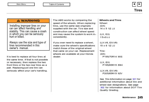
TiresIt is best to replace all four tires at the same time. If that is not possible or necessary, then replace the two front tires or the two rear tires as a pair. Replacing just one tire can seriously affect your car's handling.The ABS works by comparing the speed of the wheels. When replacing tires, use the same size originally supplied with the car. Tire size and construction can affect wheel speed and may cause the system to work in-consistently.If you ever need to replace a wheel,make sure the wheel's specifications match those of the original wheel that came on your car. Replacement wheels are available at your Honda dealer.Wheels and Tires Wheel:(DX)14 x 5 1/2 JJ (LX, EX)15x 6J J (LX-V6, EX-V6)15 x 6 1/2 JJ Tire:(DX)P195/70R14 90S (LX, EX)P195/65R15 89H (LX-V6, EX-V6)P205/65R15 92VSee Tire Information on page 301 for additional information about tire and wheel size designations. See page 302 for information about DOT Tire Quality Grading.MaintenanceTiresWinter DrivingTires that are marked "M + S" or "All Season" on the sidewall have an all-weather tread design. They should be suitable for most winter driving conditions. Tires without these markings are designed for optimum traction in dry conditions.They may not provide adequate performance in winter driving.For the best performance in snowy or icy conditions, you should install snow tires or tire chains. They may be required by local laws under certain conditions.Snow TiresIf you mount snow tires on your Honda, make sure they are radial tires of the same size and load range as the original tires. Mount snow tires on all four wheels to balance your car's handling in all weather conditions. Keep in mind the traction provided by snow tires on dry roads may not be as high as your car'soriginal equipment tires. You should drive cautiously even when the roads are clear. Check with the tire dealer for maximum speed recommenda-tions.Tire ChainsMount snow chains on your vehicle when warranted by driving condi-tions or required by local laws. Make sure the chains are the correct size for your tires. Install them only on the front tires.4-cylinder modelsIf metal chains are used, they must be SAE class "S". Cable-type traction devices can also be used.6-cylinder modelsUse only SAE class "S" cable-type traction devices.When installing chains, follow the manufacturer's instructions and mount them as tightly as you can.Drive slowly with chains installed. If you hear the chains contacting the body or chassis, stop and investigate.Make sure the chains are installed tightly, and that they are not contacting the brake lines orsuspension. Remove the chains as soon as you begin driving on cleared roads.Chains of the wrong size or that are improperly installed can damage your car's brake lines, suspension, body, and wheels. Stop driving if you hear the chains hitting any part of the car.MaintenanceNOTICE。
洗衣机使用说明书型号XQB80-Z1269• 本说明书为通用手册• 本公司保留说明书解释权• 产品外观请以实物为准• 阅后请与发票一并妥善保存• 如遇产品技术或软件升级,恕不另行通知• 本产品只适合在中国大陆销售和使用1. 产品介绍1 1.1. 产品介绍1 1.1.1. 部件介绍1 1.2. 技术规格21.2.1. 参数介绍22. 使用说明4 2.1. 安全注意事项4 2.1.1. 图示说明4 2.1.2. 警告类4 2.1.3. 注意类4 2.2. 洗衣机的安装5 2.2.1. 拆除包装5 2.2.2. 洗衣机的放置6 2.2.3. 洗衣机的调平6 2.2.4. 排水管7 2.2.5. 进水管7 2.3. 洗涤注意事项11 2.3.1. 不可洗涤衣物11 2.3.2. 检查衣物11 2.3.3. 衣物分类洗涤15 2.3.4. 重污衣物预处理16 2.3.5. 衣物放入方法18 2.3.6. 衣物洗涤重量参考19 2.4. 洗衣操作19 2.4.1. 洗衣步骤19 2.4.2. 操控界面20 2.4.3. 开机20 2.4.4. 程序21 2.4.5. 参数22 2.5. 清洁保养25 2.5.1. 线屑过滤器25 2.5.2. 进水阀过滤网272.5.3. 箱体与内桶303. 售后服务32 3.1. 疑问解答32 3.1.1. 问题解答32 3.1.2. 显示代码及处理方法34 3.2. 有害物质343.2.1. RoHS有害物质说明34 3.3. 售后服务34 3.3.1. 保修说明351. 产品介绍1.1. 产品介绍1.1.1. 部件介绍本电子说明书使用的配图均为示意图,由于产品改进及系列化扩展,您所得到的产品外观、颜色及功能部件可能与此图片不一致,请以实际产品为准。
洗衣机各部件名称 (正面示意图)洗衣机各部件名称(背面示意图)附件1.2. 技术规格1.2.1. 参数介绍技术数据智能双宽:宽电压:187V~253V(当电压波动较大时整机可运行,但性能可能会有衰减);宽水压:当水压较小时整机可运行,但洗涤剂、洗衣粉或柔顺剂冲洗效果等性能会衰减。
卖海尔洗衣机的基础操作流程下载温馨提示:该文档是我店铺精心编制而成,希望大家下载以后,能够帮助大家解决实际的问题。
文档下载后可定制随意修改,请根据实际需要进行相应的调整和使用,谢谢!并且,本店铺为大家提供各种各样类型的实用资料,如教育随笔、日记赏析、句子摘抄、古诗大全、经典美文、话题作文、工作总结、词语解析、文案摘录、其他资料等等,如想了解不同资料格式和写法,敬请关注!Download tips: This document is carefully compiled by theeditor. I hope that after you download them,they can help yousolve practical problems. The document can be customized andmodified after downloading,please adjust and use it according toactual needs, thank you!In addition, our shop provides you with various types ofpractical materials,such as educational essays, diaryappreciation,sentence excerpts,ancient poems,classic articles,topic composition,work summary,word parsing,copy excerpts,other materials and so on,want to know different data formats andwriting methods,please pay attention!1. 了解产品。
熟悉海尔洗衣机的各种型号、功能和特点。
掌握不同型号之间的差异,以便能够根据客户需求进行推荐。
MX4、MX6 系列多联机售后培训资料(原奥蕴多联机、奥蕴VILLA 系列)RFC226/280/335/400/450MX6(原KMR-226/280/335/400/450W/D532B(NEW))RFC250/300/350/400/450MX4(原KMR-250/300/350/400/450W/D532S(新))青岛海尔空调电子有限公司目录一、机型简介二、系统介绍三、奥蕴多联拨码开关四、故障代码表及故障排查五、奥蕴多联检测工装使用六、常见问题分析与解决一、机型简介1.1 原奥蕴多联、奥蕴VILLA 统一成三菱重工型号命名法则室内机:1.2、原奥蕴多联、奥蕴VILLA 与MX4、MX6 系列机型对照表匹数原奥蕴多联型号对应三菱新型号原奥蕴VILLA型号对应三菱新型号8HP KMR-226W/D532B(NEW)RFC226MX6 KMR-250W/D532S(新)RFC250MX4 10HP KMR-280W/D532B(NEW)RFC280MX6 KMR-300W/D532S(新)RFC300MX4 12HP KMR-335W/D532B(NEW)RFC335MX6 KMR-350W/D532S(新)RFC350MX4 14HP KMR-400W/D532B(NEW)RFC400MX6 KMR-400W/D532S(新)RFC400MX4 16HP KMR-450W/D532B(NEW)RFC450MX6 KMR-450W/D532S(新)RFC450MX4 注:1)KMR-*W/D532B(NEW)机型与不带(NEW)的机型区别在于:带(NEW)的机型采用的压缩机驱动模块为自制模块,不带(NEW)的型号于2010 年 4 月分淘汰;2)KMR-250W/D532S(新)机型与不带(新)机型区别在于:带(新)的机型采用交流电机,不带(新) 机型为直流电机,和*W/D532B 系列机型电机一样,该机型在MX4 机型上市后即将淘汰。
实训二全自动洗衣机一、实训目的1、理解自控成型机的工作原理。
2、掌握编程软件的使用以及对程序的输入、检查、修改和运行调试。
3、掌握I/O口的分配和I/O口的接法。
二、实训器材1、亚龙PLC主机单元一台。
2、亚龙PLC自控成形机单元一台。
3、计算机或编程器一台。
4、安全连线若干条。
5、PLC串口通讯线一条。
三、实训原理全自动洗衣机的工作方式:(1)按启动按钮,首先进水电磁阀打开,进水指示灯亮。
(2)按上限按钮,进水指示灯灭,搅轮在正反搅拌,两灯轮流亮灭。
(3)等待几秒钟,排水灯亮,后甩干桶灯亮了又灭。
(4)按下限按钮,排水灯灭,进水灯亮。
(5)重复两次(1)—(4)的过程(6)第三次按下限按钮时,蜂鸣器灯亮10秒钟后灭,整个过程结束。
(7)操作过程中,按停止按钮可结束动作过程。
(8)手动排水按钮是独立操作命令,按下手动排水后,必须要按下限按钮。
四、I/O分配表五、I/O接线图六、实训步骤1、先将PLC主机上的电源开关拨到关状态,严格按图接线,注意12V和24V电源的正负不要短接,电路不要短路,否则会损坏PLC触点。
2、将电源线插进PLC主机表面的电源孔中,再将另一端插到220V电源插板。
3、将PLC主机上的电源开关拨到开状态,并且必须将PLC串口置于STOP状态,然后通过计算机或编程器将程序下载到PLC中,下载完后,再将PLC的串口置于RUN状态。
4、实训操作按工作方式操作。
七、实物接线图八、实训小结通过本次实训理解自控成型机的工作原理,掌握编程软件的使用以及对全自动洗衣机程序的输入、检查、修改和运行调试。
掌握I/O口的分配和I/O口的接法。
学会的全自动洗衣机程序的编写与实物连接。
发现不足并改正。
海尔波轮全自动洗衣机操作使用说明一.洗前准备1.确认衣物有无特殊洗涤要求,不易吸水的衣物请用手按入水中。
2.清理衣袋,将硬币、砂子、发夹等物品取出3.将长带打结、纽扣扣好、拉链拉好4.洗涤物不应过量,投入前衣物展开抖松5.洗衣机运转时,衣物的纽扣可能会发出声音,为慎重起见,将带有纽扣的衣物放在衣物当中二.洗涤剂的使用1.洗衣粉a 模糊程序(标准)及预约洗涤时,建议将洗衣粉直接投入洗衣粉盒使用b 在洗衣机内直接融化(不适用于模糊程序(标准)及预约洗涤):注入少量水(选择最低水位)→放入洗衣粉,运转约30秒钟,使之充分溶化后按动“启动/暂停”→放入洗涤物,选择合适水位,再次按动“启动/暂停”c 准备约30℃的温水和容器→边搅拌边放入洗衣粉,使之充分溶化→将溶解液倒入洗衣机d洗衣粉用量参考洗衣粉说明,建议不要使用高泡洗衣粉2.漂白剂注水至规定水位后,将漂白剂用容器稀释后,慢慢倒入液体洗涤剂注入口。
3.液体洗涤剂将液体洗涤剂倒入液体洗涤剂注入口。
三.投放洗涤物一次洗涤以放入适量洗涤物,洗涤过程中洗涤物能正常翻转为宜。
1.0kg以下的布量不要选择高水位,以防水滴飞溅。
四.洗涤程序操作操作流程:电源/暂停→程序→水量→启动/暂停流程说明:1.按动“电源开/关”按钮,开启电源2.按动“程序”按钮,选择合适的全自动程序,默认为“大物”3.按动“水量”按钮:选择适合衣物洗涤的用水量,注意“快速”程序和“脱水”程序均无法选择水量。
4.按动“启动/暂停”按钮五.关闭上盖在脱水过程中,如打开上盖,洗衣机会停止运行并报警。
六.洗衣结束洗衣过程结束后,洗衣机蜂鸣报警,然后自动断电。
★注意事项:1.不要洗涤雨衣、自行车罩等防水性衣物,以免异常振动或损坏衣物。
2.不要将如何热的、重的物品、湿的衣物放在洗衣机上,尤其是程序操作面板上。
3.不要使用50℃以上的热水洗衣物。
4.洗衣机正在工作时,请勿拔下电源插头或切换电源,更不能用湿手拔电源插头。