沃尔沃标准 VCS 1027,61319 橡胶材料耐液性[中文]
- 格式:doc
- 大小:41.50 KB
- 文档页数:7
nbs耐磨的测试和标准
NBS(Nordic Ball Sliding)耐磨测试是一种常用的测试方法,用于评估材料的耐磨性能。
该测试通过使用一颗固定形状和质量的钢球在特定负荷下在材料表面滑动,并衡量钢球滑动一定距离后对材料造成的磨损。
NBS耐磨测试的标准可以根据不同的应用领域和材料类型而有所不同。
以下是一些常见的NBS耐磨测试标准:
1. ASTM G133:用于评估建筑涂料和涂层的耐磨性能。
2. ASTM D1630:用于评估塑料和橡胶材料的耐磨性能。
3. ISO 4649:用于评估橡胶材料的耐磨性能。
4. GB/T 9867:用于评估橡胶材料的耐磨性能。
这些标准中通常会规定测试参数,如滑动速度、负荷、测试周期等,以确保测试结果的可比性和可重复性。
1 4Issue PageThe English language version is the original and the reference in case of dispute.此英文版为初始版,如有争议,以英文版为准。
TEST METHOD 试验方法Odour of trim materials in vehicles汽车装饰材料气味Organic materials有机材料Orentation引言This standard is a further development of standard STD 1027,2712, issue 1, which it replaces and from which it differs in that the requirements under section 3.1 ”Conditioning of test pieces” have been changed.本标准是标准STD 1027,2712,版本1的延伸,该标准在章节3.1:测试件条件做了更改,区别并代替以前版本。
This standard conforms to VDA 270, Versions A2, B2 and C2, with the exception that the test has been extended to include placing a set of test pieces in a test vessel without water.除了该实验扩展到了在无水试验容器中包含一套试验样件外,本标准和VDA 270, 版本 A2, B2 和 C2是一致的。
Contents 内容1 Scope and field of application范围和适用性2 Apparatus 设备3 Test pieces 测试件3.1 Conditioning of test pieces测试件条件3.2 Quantity of materials for testing测试材料数量4 Testing 测试5 Evaluation评估6 Test report 试验报告1 Scope and field of application 范围和适用性The purpose of the test is to assess odour under the influence of temperature and moisture. The test is performed on materials from the interior of vehicles and on components that come into contact with the air flow supplied to the interior of vehicles.本试验目的在于在温度和湿度影响下评估气味。
Volvo Car Cor por a t ionIssue 4 Page 1 Dept / Issued by 6857 Thomas Andersson Issue 4 Established 2004-01 UM Page 1(9)The English language version is the original and the reference in case of dispute.此英文版为初始版,如有争议,以英文版为准。
TEST METHOD试验方法Fogging 雾化Organic materials有机材料Orientation 定位As to its technical content, this standard conforms to ISO 6452:2000.本标准技术内容符合ISO 6452:2000。
This issue differs from issue 3 in that sections 4, 4.5, 4.6, 5, 6.1.3, 6.1.4.2, 6.2.3 and 6.2.4.3 have been changed.本问题在不同于问题3,因为章节4, 4.5,4.6, 5, 6.1.3, 6.1.4.2, 6.2.3 和 6.2.4.3作了修改。
Contents1 Field of application适用领域2 Definition 定义3 Reagents 试剂4 Apparatus 设备5 Test piece 测试件6 Test procedure 测试步骤6.1 Method F (reflectometric method, evaluationof fogging using a glossmeter)方法F(反射法,用光泽及评估雾化)6.2 Method G (gravimetric method, evaluation offog- ging using balance)方法G(重量法,用天平评估)7 Report 报告1 Field of application 适用领域This method covers determination of the fogging characteristics of organic materials.本标准涵盖了有机材料雾化属性的测定。
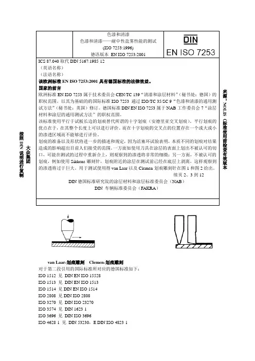
van Laar-划痕雕刻 Clemen-划痕雕刻对于第二段引用的国际标准所对应的德国标准如下:ISO 1512 见 DIN EN ISO 15528ISO 1513 见 DIN EN ISO 1513ISO 1514 见DIN EN ISO 1514ISO 2808 见DIN ISO 2808ISO 3270 见 DIN ISO 23270ISO 3574 见 DIN 1623-1ISO 3696 见 DIN ISO 3696ISO 4628-1 见 DIN 53230,E DIN ISO 4823-1大众集团 按照DIN说明进行复制ISO 4628-2 见DIN 53209,E DIN ISO 4823-2ISO 4628-3 见DIN 53210,E DIN ISO 4823-3ISO 4628-4 见DIN ISO 4628-4,E DIN ISO 4823-4ISO 4628-4 见DIN ISO 4628-5,E DIN ISO 4823-5修改相对于DIN 53167:1985-12对如下内容进行了修改:等效采用国际标准ISO 7253:1996的规定。
无本质性的变动,因为以前的版本标准DIN 53167:1985-12对测试的描述在内容上与国际标准ISO 7253一致。
ISO 4628-8应采纳DIN 53176:1985-12对样板评价的描述,并计划作为欧洲标准(DIN EN ISO 4628-8)采用。
以前的版本DIN 53167:1972-08,1985-12国家的附录(NA)(资料性附录)国家之间的附录的文献指示DIN 53209,涂层气泡度的标志DIN 53210,涂层或类似的涂覆层的生锈标志DIN 53230,涂料和类似的涂覆层材料的检验——检验的分析结果鉴定系统DIN EN 10130 用于冷变型的低碳钢冷轧板——交货技术条件DIN EN 23270,清漆和色漆以及它们的材料——预处理和试验用的温度和湿度(ISO 3270:1984);德语版本EN 23270:1991DIN EN ISO 1513,清漆和色漆——用于进一步测试的取样的预测试和准备(ISO 1513:1992);德语版本EN ISO 1513:1994。
VOLVOVolvo Car Corporation 沃尔沃汽车公司Standard 标准VCS 1029,54719Dept / Issued by Magnus Karlsson Issue 2 Established 2006-04 UM 部门/发行人:Magnus Karlsson 第2版,2006-04 UM 制定Page 1(9) 第1(9)页TEST METHOD测试方法Adhesion, water spraying under high-pressure粘附性,高压喷水 Paints and enamels涂料和搪瓷Orientation简介This issue differs from issue 1 in that an alternative for when scribing shall be made has been included.Furthermore, the manufacture of the spray nozzlehas been specified, and the material for calibrationhas been changed. Handling after moisture exposure has been clarified.本版本与第1版的区别在于包含了划线的替代方法。
此外,已经规定了喷嘴的制造程序,已经更改了校准的材料。
已经澄清了暴露于潮湿环境后的处理程序。
1 Scope and field of application1 应用范围和领域This test method is used for assessing the adhesion between paint films and between paint film and substrate respectively. The method is intended to simulate the strain and load that the paint films are subjected to during high-pressure cleaning.本测试方法用于评估漆膜之间以及漆膜和基材之间的粘附性。
Dept / Issued by 93733 Magnus Karlsson Issue 2 Established2007-03UM Page1(2)The English language version is the original and the reference in case of dispute. Den engelska språkversionen är originalversion och skall åberopas i händelse av tvist.TEST METHOD PROVNINGSMETODEvaluation degrees for blistering of paints Utvärderingsskala för blås-bildning hos färgerPaints and enamels Färg och lackOrientation OrienteringAs to its technical content, this standard conforms to ISO 4628-2:2003.This issue of the VCS standard differs from issue 1 by:−Referring to ISO 4628-2:2003 and its pictorial standards−Giving an alternative evaluation method by rating the density of each size of blistersseparately−Defining the blister size of each size rating number as a guide for the assessment −Describing the assessment procedure more thoroughly−Describing how to evaluate very small blisters (< 0,05 mm). Denna standard överensstämmer i sak medISO 4628-2:2003.Denna utgåva av VCS-standarden skiljer sig frånutgåva 1 genom att:−Referera till ISO 4628-2:2003 och dessbildlikare−Ange en alternativ utvärderingsmetod där tätheten av varje storleksklass av blåsorbetygssätts separat−Definiera blåsornas storlek inom varjestorleksklass som en vägledning vidbedömningen−Beskriva bedömningsproceduren mergenomgående−Beskriva hur mycket små blåsor (< 0,05 mm) utvärderas.1 Scope 1 OmfattningThis standard is intended to be used when determin-ing the degree of blistering of paint coatings on test objects, which have been tested or used under accelerated or atmospheric conditions. Standarden är avsedd att användas vid bestämning av blåsbildningsgrad i lackskikt på provobjekt som provats eller använts under accelererade eller atmos-färiska betingelser.2 Definitions 2 DefinitionerBlisters are defined as moisture-containing enclosures in the paint film.The degree of blistering is defined as the rating number of the density and the size of blisters in a coating. Blåsor definieras som fuktinnehållande inneslutningar i lackskiktet.Blåsbildningsgraden definieras som betygsklassen för blåsornas täthet och storlek i en lackfilm.3 Assessment 3 BedömningThe test objects shall be examined before the accelerated test to identify dirt and other defects in the paint film. These shall be marked to avoid them to be mixed up with blisters caused by the test. Provobjekten skall bedömas före den accelererade provningen för att identifiera smuts och andra defekter i lackskiktet. Dessa ska markeras för att undvika att de förväxlas med blåsor som orsakas av provningen.Issue2Page2Unless otherwise specified, the degree of blistering shall be assessed immediately after completion of the accelerated test. The test objects shall be examined under good illumination, from closer than arm's length and from all viewing angles. The density and size of the blisters shall be assessed by means of the pictorial standards in ISO 4628-2:2003. Thesepictorial standards illustrate blisters in densities 2, 3, 4 and 5 and, for each density, blisters of sizes S2, S3, S4 and S5.Om inget annat anges ska blåsbildningsgraden bedömas omedelbart efter avslutad accelererad provning. Provobjekten skall bedömas i godbelysning, inom armlängds avstånd och från alla betraktelsevinklar. Blåsornas täthet och storlek skall bedömas med hjälp av bildlikarna i ISO 4628-2:2003. Dessa bilder visar blåsor i tätheterna 2, 3, 4 och 5 och för varje täthet blåsor i storlekarna S2, S3, S4 och S5.It is then decided which of the pictorial standards that best matches the blistering of the test object. The degree of blistering is then the rating number of density and size of that pictorial standard. Den bildlikare som bäst överensstämmer med blåsbildningen på provobjektet bestäms. Blås-bildningsgraden är då betygsklassen för täthet och storlek som anges för denna bildlikare.If the rating for density and size respectively is less than 2, the rating is 1. If there are no blisters, the rating is 0.Bedöms täthet respektive storlek vara mindre än 2 blir betyget 1. Finns inga blåsor blir betyget 0.If none of the pictorial standards match the blistering of the test object, an alternative evaluation method can be used. By rating the density of each size of blisters separately, a combined rating is obtained. For example: The blisters of a test object are assessed to have density 3 of size S1 and density 2 of size S4. The degree of blistering is then 3(S1) + 2(S4). Om ingen bildlikare överensstämmer medblåsbildningen på provobjektet, kan en alternativutvärderingsmetod användas. Genom att betygssätta tätheten av varje storleksklass för sig erhålls ett sammansatt betyg. Till exempel: Blåsorna på ettprovobjekt bedöms ha tätheten 3 av storleken S1 och tätheten 2 av storleken S4. Blåsbildningsgraden är då 3(S1) + 2(S4).In case of uncertainty regarding the size rating of the blisters, the table below can be used as a guide.Vid osäkerhet angående storleksbedömning av blåsorna, kan tabellen nedan vägleda. Size rating number StorleksklassMean diameter of blister (d)Medeldiameter av blåsa (d) S1 d ≤ 0,5 mmS2 0,5 < d ≤ 1 mm S3 1 < d ≤ 2 mm S42 < d ≤ 4 mm S5d > 4 mmBlisters smaller than 0,05 mm (hair diameter) shall not be evaluated as blisters if they disappear within 24 h, stored at 23 ± 2°C and 50 ± 5% RH, after completion of the accelerated test.Blåsor som är mindre än 0,05 mm (hårdiameter) skall inte bedömas som blåsor om de försvinner inom 24 h, vid förvaring i 23 ± 2°C och 50 ± 5 % RF, efter avslutad accelererad provning.4 Test report4 RapportThe test report shall include: a) Identification of the test object. b) Testing as per VCS 1027,0519.c) The numerical rating of the density and size ofblistering. I provrapporten anges: a) Identifiering av provobjektet. b) Provning enligt VCS 1027,0519. c) Blåsornas täthetsklass och storleksklass.。
Established Date: Issue: Page: 2014-04 3 1(10)The English language version is the original and the reference in case of dispute. Den engelskspråkiga versionen är originalversion och ska åberopas i händelse av tvist.COMPUTER-AIDED DESIGN DATORSTÖDD KONSTRUKTIONDigital Shape Model basis – DSM basis Numerisk formmodell bas – DSM-basOrientation OrienteringThis issue differs from issue 2 in that the content of the standard has been expanded to also cover the case with an annotated geometry model (3D). Denna utgåva skiljer sig från utgåva 2 genom att standarens innehåll har utökats till att också omfatta fallet med en annoterad geometrimodell (3D).1 Scope and field of application 1 Omfattning och tillämpningThis standard establishes the rules that apply when using a digital shape model for the description of nominal geometry. Standarden lägger fast vad som gäller när en numerisk formmodell används för att beskriva nominell geometri.Rules for how CATIA V5 models shall be made are given in standard VCS 5027,1. Regler för hur CATIA V5-modeller ska vara utformade finns i standard VCS 5027,1.The rules in VCS 5023,059 “General require-ments for the execution of drawings” apply to DSM basis. Reglerna i VCS 5023,059 ”Allmänna krav på ritningars utförande” gäller för DSM-bas.2 Definitions 2 DefinitionerDigital shape model (DSM) Numerisk formmodell (DSM)A geometric representation of a part using mathematical formulas to describe form features and topology, stored in a reference position. En geometrisk representation av en artikel vilken använder matematiska formler för att beskriva formegenskaper och topologi och som lagrats i ett referensläge.The concept ”DSM basis” shall be used as a term when the digital shape model is included in the product-defining basic material. Begreppet ”DSM-bas” används som term när den numeriska formmodellen ingår i det produktdefinierande underlaget.3 Rules 3 ReglerWhen dimensions are indicated on the drawing or displayed on a model, these dimensions apply. Då mått angetts på ritningen eller visas utskrivna i modellen gäller dessa mått.Dimensions that are indicated on the drawing or displayed on a model shall be in conformance with the DSM but shall be rounded to the number of decimal places required for the function. Mått som angetts på ritning eller visats utskrivna i modellen ska överensstämma med DSM men avrundas till lämpligt antal decimaler efter vad som krävs för funktionen.3 2(10)When dimensions are omitted on the drawing or not displayed on a model, the DSM basis applies. These dimensions shall be obtained by analyzing the model.När mått saknas på ritning eller inte visautskrivna i modellen gäller DSM-bas. Dessa mått ska då erhållas genom analys av modellen. Note - Dimensions intended as information only shall be given within brackets in accordance with the ordinary drawing rules.Anm: Mått som enbart är för information ges inom parantes enligt ordinarie ritregler.4 Drawing and digital shape model (DSM) in combination4 Ritning och numerisk formmodell (DSM) i kombinationIn order to provide a complete definition of a part, a drawing and a digital shape model (DSM) are often used in combination För att ge en komplett definition av en artikelanvänds ofta en kombination av en ritning och en digital model (DSM).The part may be represented on a drawing using one ore more orthographic or axonometric views and sections. Figure 1 shows a digital shapemodel without any annotation. A drawing shall be used along with it to provide geometrical and other requirements.En artikel kan beskrivas på en ritning med en eller flera ortografiska eller axonometriska vyer och snitt. Figur 1 visar en digital formmodell utan några annoteringar. En ritning ska då användas tillsammans med den för att ge geometriska och andra krav.Fig. 1 Digital Shape Model (DSM) – Numerisk formmodell (DSM)Figure 2 gives an example of an orthographic drawing depicting the modelled part. The drawing shall contain a note stating that the digital model (DSM) is basis for dimensions not stated on the drawing.I figure 2 visas ett exempel på ortografisk ritning som återger den modellerade artikeln. Ritningen ska då innehålla en not som säger att dendigitala modellen (DSM) är bas för mått som ej anges på ritningen.3 3(10)Fig. 2 Orthograhic drawing to be used along with the DSM / Ortografisk ritning som ska användas tillsammans med DSM5 Annotated geometry model (3D)5 Annoterad geometrimodell (3D)The annotaded geometry model shall provide complete product definition, for example, a digital model (DSM), its annotation and all related documentation.Den annoterade geometrimodellen skainnehålla en komplett definition av artikeln, t.ex. en digital modell (DSM), dess annoteringar och all relaterad dokumentation.When all indications of dimensions, tolerances and surface texture are done directly in 3D, the rules how to indicate are mainly the same as in 2D but, for some special cases, the rules have been slightly modified for indication in 3D.När all angivning av mått, toleranser, ytstruktur görs direkt i 3D är angivningsreglerna i stort desamma som för 2D men för vissa speciella fall så har reglerna modifierats något för angivning 3D.In this standard, the cases where the indication rules have been modified or clarified are shown. I denna standard visas de fall där reglerna har modifierats eller förtydligats för att fungera i 3D. For some cases, also the indication rules for 2D give several ways to indicate the same thing where one of those is especially suitable for indication in 3D. This standard also shows a few such cases. I vissa fall ger också angivningsreglerna för 2D flera alternativ för att markera samma sak varav något av dessa är speciellt lämpligt förangivning i 3D. I denna standard visas också några sådana fall.A general rule for specification of requirements in 3D is that a single extension line from a surface shall not be used fo indication.En generell regel vid kravsättning i 3D är att en ensam förlängningslinje från en yta inte ska användas att markera mot.3 4(10)5.1 Lines in a specific direction5.1 Linjer i bestämd riktningWhen tolerancing lines on a surface, the rule in 2D is that the direction of the lines is parallel to the projection plane in that view where the tolerance is given. However, this rule does not work in 3D. Vid toleranssättning av linjer på en yta är regeln i 2D att riktningen på linjerna är parallella med projektionsplanet i den vy där kravet visas. Denna regel fungerar inte vid angivning i 3D. At indication in 3D, the direction of the lines can be given with a line as shown in figure 3. This way to indicate is equivalent to the rule from the projection plane in 2D.Vid angivning i 3D kan riktningen visas med en linje såsom visas i figur 3. Detta angivningssätt är likvärdigt med regeln via projektionsplanet i 2D.Fig. 3In ISO 1101:2012, a possibility to indicate thedirection of the tolerance lines by the use of a new symbol placed after the tolerance frame was also introduced. See example in figure 4.I ISO 1101:2012 infördes också en möjlighet att ange de toleranssatta linjernas riktning genom att använda en ny symbol som placeras efter toleransrektangeln. Se exempel i figur 4. The indication in figure 4 is a little moreunambiguous than the indication with a line since a specific surface is used as a basis when determining the direction of the lines.Angivningen i figur 4 är ju något tydligare än sättet att markera en linje eftersom man med den nya symbolen utgår från en bestämd yta när riktningen på linjerna bestäms.3 5(10)The meaning of the example in figure 4 is that the tolerance applies to all lines on the surface that are perpendicular to datum B. Exemplet i figur 4 ger betydelsen att toleransen gäller alla linjer på ytan som är vinkelräta mot referens B.Fig. 45.2 Indication of a geometricaltolerance to the axis of a diameter5.2 Angivning av form- ochlägetolerans för centrumlinjen av en diameterTo indicate in 2D that a geometrical tolerance shall apply to the axis, the annotation used has since long been that the line from the tolerance frame shall be against the diameter dimension as shown in figure 5.Då en form- och lägetolerans ska gälla för centrumlinjen har angivningssättet i 2D sedan lång tid tillbaka varit att man markerar mot diametermåttet såsom visas i figur 5.Indication in accordance with figure 5 is however not so practical in 3D where you wish, as far as possible, to avoid the use of extension lines for dimensioning.Angivningsättet enligt figur 5 är dock opraktiskt i 3D då man så långt som möjligt vill undvika utdragna måttgränslinjer.3 6(10)Therefore, a new possibility to indicate that ageometrical tolerance applies to the axis has been added in the new versions of the tolerancingstandards. This is done by indicating the symbol A (the letter A within a circle) after the tolerance value; then it is possible to indicate against thesurface, see figure 6. The letter A stands for “Axis”. I toleransstandarderna har därför nu också införts möjligheten att ange att form- ochlägetoleransen gäller för centrumlinje genom att markera med symbolen A (bokstaven A i en cirkel) efter toleransvärdet och då kan manpeka mot ytan, se figur 6. Bokstaven A kommer från engelska ordet ”Axis”.Fig. 5Fig. 6The indication in 3D can than be as shown infigure 7. The straightness tolerance then applies to the axis of the smaller diameter.I 3D kan då angivningen göras såsom visas i figur 7 där rakhetstoleransen då gäller för centrumlinjen för den mindre diametern.Fig. 75.3 Indication of a datum to be the axisof a diameter5.3 Angivning av referens somcentrumlinje för en diameterWhen a datum shall be the axis of a diameter, the way to indicate has since long been that thesymbol for the datum shall be placed against the diameter dimension as shown with datum A in figure 8.Då en referens ska vara centrumlinjen för en diameter har angivningssättet sedan lång tid varit att man markerar symbolen för referens som en förlängning av diametermåttet såsom visas med referens A i figur 8.3 7(10)The way to indicate datum A in accordance with figure 8 is, however, not so practical in 3D when you wish, as far as possible, to avoid the use of extension lines for dimensioning.Angivningsättet med referens A är dockopraktiskt i 3D då man så långt som möjligt vill undvika utdragna måttgränslinjerTherefore, a new possibility to indicate that a datum is the axis by placing the symbol for the datum directly underneath a diameter dimension, as shown with datum B in figure 8, has been introduced in the new versions of the tolerancing standards. The meaning is then that the datum is the axis of that diameter.I toleransstandarderna har därför nu också infört möjligheten att ange referenssymbolen direkt under ett diametermått såsom visas med referens B i figur 8. Betydelsen är då attreferensen är centrumlinjen av den diametern.Fig. 85.4 Median plan as toleranced featureor as a datum5.4 Mittplan som toleransbestämtelement eller som referensWhen a median plane of a width shall be the toleranced feature or a datum, it is howevernecessary to use extension lines for dimensioning. See figure 9.Då ett mittplan ska vara toleransbestämtelement eller utgöra referens måste man dock använda utdragna måttgränslinjer. Se figur 9.Fig. 93 8(10)5.5 Examples of indications5.5 AngivningsexempelFigures 10 and 11 contain examples of indication where applications of the above-mentioned rules can be found.I figurerna 10 och 11 visas angivningsexempel där man kan se tillämpningar av ovanstående regler.Fig. 10Fig. 113 9(10)5.6 Indication of surface texture5.6 Angivning av ytstrukturWhen requirements on surface texture areindicated in 3D, the indication rules are mainly the same as in 2D. However, the symbol for surface texture shall not be placed against a single extension line from a surface.Vid angivning av ytstrukturkrav i 3D ärangivningsreglerna i stort samma som i 2D. Symbolen för ytstruktur ska dock inte anges mot en ensam förlängningslinje från en yta. The rule in 2D to indicate that the direction of the surface lay is parallel or perpendicular to theprojection plane in that view where the requirement is given does not work in 3D.Regeln som finns i 2D för att ange att riktningen på bearbetningsspåren ska vara parallell eller vinkelrät mot projektionsplanet i den vy där kravet visas fungerar dock inte i 3D.When this shall be indicated in 3D, a line element can be added to correspond to the projection plane in 2D. In figure 12, there is an example of this with the meaning that the direction of the surface lay shall be perpendicular to the shown line element.I 3D kan man för detta ange ett linjeelement som kan sägas motsvara projektionsplanet i 2D. Ett exempel visas i figur 12 där betydelsen då är att riktningen på bearbetningsspåren ska vara vinkelrät mot det visade linjeelementet.Fig. 123 10(10)5.7 Other indications in 3D5.7 Andra angivningar i 3DWhen it comes to other types of indications in 3D, e.g. different requirements for joining, the ordinary rules for indications in 3D apply. Figure 13 shows an example of indication of spot welds.När det gäller andra typer av angivningar, t.ex. olika krav på fogning, så följer man de ordinarie reglerna för visning 3D. I figur 13 visas ett exempel på angivning av punktsvetsar.Fig. 136 Reference to this standard6 Hänvisning till denna standardReference to this standard shall be done with the following note:Hänvisning till denna standard ska göras med följande not:DIGITAL SHAPE MODEL IS BASIS WHERE DIMENSIONS ARE OMITTED VCS 5027,39When a drawing shall be used in a combination with a digital shape model (DSM), the text note shall be indicated on the drawing.När en ritning används i kombination med den digitala modellen (DSM) ska textnoten anges på ritningen.When only an annotated geometry model (DSM) is used, the text note shall be indicated in this model. När endast annoterad geometrimodell (DSM) används ska textnoten anges i denna modell.。
Dept / Issued by 93663 Magnus Jarlid Issue 3 Established 2012-06 Page 1(2)The English language version is the original and the reference in case of dispute. Den engelska språkversionen är originalversion och ska åberopas i händelse av tvist.TEST METHOD PROVNINGSMETODConditioning of painted test panels before testing Konditionering av lackerade provpaneler före provningPaints and enamels Färg och lack Orientation OrienteringThis issue differs from issue 2 in that reference to DIN 50014 has been removed. Denna utgåva skiljer sig från utgåva 2 genom att hänvisning till DIN 50014 är borttagen.1 Scope and field of application 1 Omfattning och tillämpningThe standard describes how consistent test conditions are obtained. Standarden beskriver hur enhetliga provningsförut-sättningar uppnås.Generally, all coating systems shall have passed the hardening and drying process applicable to the paint material in question before post-curing and conditioning are carried out in accordance with section 3. Generellt gäller för alla lacksystem att de ska ha ge-nomgått de för lackmaterialet gällande processen för härdning respektive torkning innan efterhärdning och konditionering utförs enligt avsnitt 3.2 Definitions 2 DefinitionerPost-curing treatment facilitates reactions (normally with moisture) of unreacted paint film species that normally would react before transportation of the vehicle to the customer. Efterhärdningsbehandling åstadkommerhärdningsreaktioner (normalt med fukt) för oreagerade specier i färgfilmen, vilka normalt skulle reagera innan fordonet transporteras till kund.Conditioning places the paint system in a normalized state regarding temperature and moisture to achieve comparable results in subsequent test programmes.Konditionering försätter färgsystemet i ett normaliserat tillstånd med avseende på temperatur och fukt för att åstadkomma jämförbara resultat i efterföljande provningsprogram.3 Procedure 3 Utförande 3.1 Post-curing 3.1 EfterhärdningPost-curing shall be performed before conditioning. Unless otherwise specified, the following applies: Efterhärdning utförs före konditionering. Om inget annat anges gäller följande:Test panels coated with one-component stoving paint systems cured at temperatures higher than 100 °C shall be conditioned in accordance with section 3.2. No post-curing is necessary. Provpaneler lackerade med 1-komponents ugns-härdande lacksystem som härdas över 100 °C ska konditioneras enligt avsnitt 3.2.Ingen efterhärdning är nödvändig.Test panels coated with two-component stoving paint systems cured at temperatures higher than 100 °C shall be post-cured for at least 48 h in standard atmosphere 23 ± 2 °C and 50 ± 5 % RH. Provpaneler lackerade med 2-komponents ugns-härdande lacksystem som härdas över 100 °C ska efterhärdas i minst 48 h i normalklimat 23 ± 2 °C och 50 ± 5 % RH.Issue 3 Page 2Test panels coated with two-component stoving paint systems cured at temperatures lower than 100 °C or two-component paint systems of room-temperature drying type shall be post-cured for at least 13 days at standard atmosphere 23 ± 2 °C and 50 ± 5 % RH. Provpaneler lackerade med 2-komponents ugns-härdande lacksystem som härdas under 100 °C eller 2-komponents i rumstemperatur torkande lacksystem ska efterhärdas under minst 13 dygn i normalklimat 23 ± 2 °C och 50 ± 5 % RH.Test panels coated with paint systems of room- temperature drying type (physically drying or oxidatively drying)shall be dried for at least 6 days at standard atmosphere 23 ± 2 °C and 50 ± 5 % RH. Alternatively, physically drying paint systems can be forced dried for 16 h at 50 °C before conditioning is carried out in accordance with section 3.2. Provpaneler lackerade med i rumstemperatur torkande lacksystem (fysikaliskt torkande eller oxida-tivt torkande)ska torkas under minst 6 dygn i normalklimat 23 ± 2 °C och 50 ± 5% RH. Alternativt kan fysikaliskt torkande lacksystem forcer-torkas under 16 h vid 50 °C innan konditioneringutförs enligt avsnitt 3.2.3.2 Conditioning 3.2 KonditioneringConditioning shall be carried out after proper post-curing as described above. Konditionering utförs efter korrekt efterhärdning enligt ovanstående beskrivning.The conditioning shall be carried out for at least 24 h at standard atmosphere 23 ± 2 °C and 50 ± 5 % RH. Konditioneringen utförs under minst 24 h i normal-klimat 23 ± 2 °C och 50 ± 5 % RH.4 References 4 ReferenserISO 3270 Paints and varnishes and their rawmaterials – Temperatures and humiditiesfor conditioning and testing ISO 3270 Paints and varnishes and their rawmaterials – Temperatures and humiditiesfor conditioning and testing。

EN10327-1-欧洲标准 EN103272004.6ICS 77.140.50; 77.140.10 替代 EN 10142:2000EN 10154:2002EN 10214:1995EN 10215:1995冷成形用连续热浸镀低碳钢钢板和钢带——交货技术条件CEN欧洲标准化委员会EN10327-2-1 范围1.1 本标准规定了厚度在0.35mm~3.0mm(除非另有协议,见1.2)的连续热浸镀低碳钢镀锌(Z)、镀锌铁合金(ZF)、镀锌铝合金(ZA)、镀铝锌合金(AZ)和镀铝硅合金(AS)(见表1)的钢板和钢带的交货技术要求。
这里的厚度是指交货产品镀层后的最终厚度。
本标准适用于所有宽度的钢带和从宽度≥600mm 的钢带剪切而成的钢板及从宽度<600mm 的钢带剪切而成的定尺产品。
1.2 如果在询价和订货时有协议,本标准也适用于厚度>3.0mm 的连续热浸镀镀层扁平材产品。
在这种情况下,产品的力学性能、镀层附着性和表面质量要求都应在订货或询价时进行协商。
1.3 本标准规定的产品主要用于那些将冷成形性和耐腐蚀性作为重要参考因素的场合下。
合金的耐腐蚀性与镀层厚度成正比(见7.3.2)。
1.4 本标准不适用于:• 结构用热浸镀镀层扁平材产品(见EN10326);• 冷轧电镀扁平材钢产品(见EN 10152);• 连续有机镀层(涂层带卷)扁平材钢产品(见EN 10169-1、EN 10169-2 和EN 10169-3)• 冷成形用较高屈服强度的连续热浸镀涂层钢板和钢带(见EN 10292)。
2 引用标准下列文件中的条款通过本标准的引用而成为本标准的条款。
凡是注日期的引用文件,仅该版本适用于本标准。
凡是不注日期的引用文件,其最新版本适用于本标准(包括修改单)。
EN 10002-1 金属材料-拉伸试验-第1部分:室温实验方法EN 10020:2000 钢牌号定义和分类EN 10021:1993 钢及钢产品交货一般技术要求EN 10027-1 钢代号体系—第1部分:钢名称、基本符号EN 10027-2 钢代号体系—第2部分:数字代号体系EN 10079 钢产品分类EN 10143 连续热浸镀金属镀层钢板和钢带—尺寸外形及允许偏差EN 10204 金属产品—检验文件的类型EN 10113 金属材料—钢板和钢带—塑性应变比的测定EN 10275金属材料—钢板和钢带—拉伸应变硬化指数的测定EN 10260 钢代号体系—补充符号3 术语和定义本标准除采用EN 10020:2000、EN 10021:1993、EN 10079:1992、EN 10204:1991中的术语和定义外,还采用如下术语和定义:注1 钢铁的防护一般导则见EN ISO 14713.注2 连续热浸镀钢带镀层的成分见3.1到3.4。
注解一般情况下,仅当橡胶厚度<4mm时,可以采用用于方法M的仪器。
4.2.4 小O型圈和曲率半径<4mm的零件用合适的夹具或blocks握住这些零件或用蜡将其固定到仪器台上。
采用方法M的仪器测量。
如果最小半径<0,8mm时,不进行试验。
5 式样按照ISO 4661-1准备式样。
5.1 方法N和M5.1.1 一般的式样的上下表面应平整、光滑并且互相平行。
在具备相同厚度的式样上进行试验。
5.1.2 厚度5.1.2.1 方法N标准式样厚度为8mm~10mm,由1、2或3层橡胶组成,其中最薄厚度应<2mm。
所有表面应平整并且平行。
非标准的式样要么较厚或较薄,但厚度不<4mm。
5.1.2.2方法M标准式样的厚度为2mm±0,5mm。
也可以使用更厚或更薄的式样,但厚度决不<1mm。
一旦是这些式样,一般情况下,读数都不会与标准式样上获得的读数达成一致。
5.1.3 侧面尺寸5.1.3.1方法N标准和非标准式样的侧面尺寸不应在从式样边缘距离<表2中展示的合适的距离执行试验。
表2—从式样边缘接触点最小距离5.1.3.2方法M侧面尺寸应不在从边缘<2mm的距离上执行试验。
当在微量试验仪器上测试厚度>4mm的式样时,因为侧面尺寸或可用的平整区域不能允许正常仪器上的试验,那么应在尽可能离边缘远的距离上执行试验。
5.2方法CN和CM式样要么是一个完整的零件或从中剪取的一片。
在硬度试验期间,应合适地支撑式样的底面。
如果执行试验的表面是布-标记的,那么试验前应擦亮此表面。
擦亮后,允许将式样在23℃的条件下恢复至少16小时,并按照§7进行调节。
此段调节期间可能形成恢复期间的一部分。
表4 D值与国际橡胶硬度IRHD之间的转换,用于方法N材料平均值实验室内实验室之间r (r) R (R) ABCD合并ABCD合并值表6 类型1精确度,中等硬度橡胶,方法N材料平均值实验室内实验室之间r (r) R (R) ABC合并值14 压痕与硬度之间的实验关系图1- 和从3到100国际橡胶硬度之间的关系图2- 和从3到40国际橡胶硬度之间的关系图3 和从80到100国际橡胶硬度之间的关系和从3到40国际橡胶硬度之间的关系15 指导使用精确度结果15.1 一般的使用精确度结果的一般程序如下所示,符号指的是任意两个测量值之间的正偏差。
vcs 1027,3379标准
VCS 1027和VCS 3379是两个标准的编号,它们分别代表着不
同的规范和要求。
VCS是"Vehicle Certification Agency"的缩写,是英国的车辆认证机构,负责制定和执行车辆认证标准。
让我们分
别来看一下这两个标准。
首先,VCS 1027标准涉及到车辆的安全认证。
这个标准通常包
括车辆的结构、安全气囊、座椅安全带、碰撞测试等方面的要求。
它确保车辆在发生事故时能够提供足够的保护,减少乘客和行人的
伤害风险。
其次,VCS 3379标准可能涉及到车辆的排放认证。
这个标准通
常包括车辆引擎的排放控制要求,以确保车辆在运行时排放的废气
符合环保标准,减少对环境的污染。
除了上述内容,这两个标准可能还涉及到车辆的制造工艺、材
料选用、电子设备等方面的要求,以确保车辆的质量和性能达到规
定的标准。
总的来说,VCS 1027和VCS 3379标准都是为了保障车辆的安
全、环保和质量而设立的,它们对车辆制造商和销售商来说是一种指导和要求,也对消费者来说是一种保障和信心。
这些标准的执行有助于提升整个汽车行业的水平,保护乘客和环境的安全与健康。
橡胶制品常用检测标准(国内版)科标橡塑实验室专业提供橡胶材料与制品的检测与分析。
橡胶制品常用标准:减震器检测:HG 2864-1997 车辆用橡胶缓撞器HG/T3080-2009防震橡胶制品用橡胶材料HG/T2866-2003 橡胶护舷JT/T 4-2004 公路桥梁板式橡胶支座JT 391-2009 公路桥梁盆式橡胶支座TB/T1893-2006 铁路桥梁板式橡胶支座TB/T2331-2004 铁路桥梁盆式橡胶支座检测JG 118-2000 建筑隔震橡胶支座HG/T2289-2001 可曲挠橡胶接头检测JT/T 327-2004公路桥梁伸缩装置HG/T3328-2006 铁路混凝土枕轨下用橡胶垫板JT/T 529-2004预应力混凝土桥梁用塑料波纹管GB/T17955-2009桥梁球型支座橡胶支座第4部分普通橡胶支座胶辊检测:HG/T2287-2008 印刷胶辊HG/T2447-2003 胶辊第4部分印染胶辊HG/T2446-2005 胶辊第5部分造纸胶辊HG/T2445-2005 胶辊第6部分电子打字(印)机胶辊HG/T 2697-2001 胶辊第二部分聚氨酯胶辊HG/T2013-2001胶辊第三部分织物预缩橡胶毯汽车零部件检测、汽车材料检测、汽车用品检测:HG/T2196-2004 汽车用橡胶材料分类系统GB/T12730-2008 一般传动用窄V带HG/T2578-1994 汽车液压制动缸用橡胶护罩HG/T2491-2009汽车用输水橡胶软管和纯胶管HG/T3088-1999 车辆门窗橡胶密封条检测GB/T15846-2006集装箱门框密封条橡胶手套检测:AQ6102-2007 耐酸(碱)手套AQ6101-2007 橡胶耐油手套GB 7543-2006 一次性使用灭菌橡胶外科手套GB 10213-2006一次性使用医用橡胶检查手套HG/T2888-1997 橡胶家用手套橡胶铺地材料检测:HG/T2015-2003 橡胶海绵地毯衬垫HG/橡塑铺地材料第1部分橡胶地板HG/橡塑铺地材料第2部分橡胶地砖橡胶鞋检测:HG/T2017-2000 普通运动鞋HG/T2016-2001 篮排球运动鞋HG/T2870-1997 乒乓球运动鞋HG/T3085-1999 橡塑冷粘鞋HG/T2018-2003 轻便胶鞋HG/T 2019-2001黑色雨靴(鞋)HG/T2020-2001 彩色雨靴(鞋)HG/T2401-1992 工矿靴HG/T2182-2008 棉胶鞋HG/T2494-2005 布面童胶鞋HG/T2495-2007 劳动鞋密封制品材料检测:HG/T2810-2008 往复运动橡胶密封圈材料HG/T2811-1996 旋转轴唇形密封圈橡胶材料GB/T9877-2008液压传动旋转轴唇形密封圈设计规范GB/T15326-1994 旋转轴唇形密封圈外观质量GB/ 密封元件为弹性体材料的旋转轴唇形密封圈第1部分:基本尺寸和公差HG/T2021-1991 耐高温滑油O型橡胶密封圈材料GB/ 液压气动用O形橡胶密封圈第2部分:外观质量检验规范HG/T3089-2001 燃油用O形橡胶密封圈材料HG/T2181-2009 耐酸碱橡胶密封件材料HG/T2579-2008 普通液压系统用0形橡胶密封圈材料GB/ 液压气动用O形橡胶密封圈第1部分尺寸系列及公差GB/液压气动用O形橡胶密封圈第2部分:外观质量检验规范GB/T12002-1989 塑料门窗用密封条HG/T3099-2004建筑橡胶密封垫预成型实心硫化的结构密封垫用材料规范TB /T1964-1987 客车门窗用密封条JB/机械密封用O形橡胶圈检测JC/T 946-2005混凝土和钢筋混凝土排水管用橡胶密封圈检测JC/T 483-2006聚硫建筑密封胶HG/T3326-2007采煤综合机械化设备橡胶密封件用胶料JC/T 748-1987(1996)预应力与自应力钢筋混凝土管用橡胶密封圈GJB 250A-1996耐液压油和燃油丁腈橡胶胶料规范GB/T15325-1994往复运动橡胶密封圈外观质量GB/往复运动橡胶密封圈结构尺寸系列第一部分单向密封橡胶密封圈GB/往复运动橡胶密封圈结构尺寸系列第二部分双向密封橡胶密封圈GB/往复运动橡胶密封圈结构尺寸第三部分橡胶防尘密封圈自动喷水灭火系统第11部分:沟槽式管接件JC/T976-2005道桥嵌缝用密封胶GB/T21873-2008橡胶密封件给、排水管及污水管道用接口密封圈材料规范HG2865-1997汽车液压制动橡胶皮碗HG2950-1999汽车制动气室橡胶隔膜GJB 5258-2003航空橡胶零件及型材用胶料规范橡胶带检测:GB/T524-2007平型传动带GB/T1171-2006一般传动用普通V带GB/T7984-2001运输带具有橡胶或塑料覆盖层的普通用途织物芯输送带检测GB/T9770-2001普通用途钢丝绳芯输送带HG/T2297-1992耐热输送带GB 13552-2008汽车多楔带HG/T3647-1999耐寒输送带GB/T13487-2002一般传动用同步带HG2014-2005钢丝绳牵引阻燃输送带HG/T2442-2001洗衣机V带HG2539-1993钢丝绳芯难燃输送带HG/T2577-2006橡胶或塑料提升带GB/T10822-2003一般用途织物芯阻燃输送带GB/T20786-2006橡胶履带GB 13552-2008汽车多楔带检测:GB 10717-1989同步带齿剪切强度试验方法GB/T7762-2003 硫化橡胶或热塑性橡胶耐臭氧龟裂静态拉伸试验GB/T1682-1994 硫化橡胶低温脆性的测定单试样法GB/T3512-2001硫化橡胶或热塑性橡胶热空气加速老化和耐热试验GB/T11545-2008 带传动汽车工业用V带疲劳试验GB/T3686-1998 三角带全截面拉伸性能试验方法GB 12732-2008汽车V带GB/T7762-2003 硫化橡胶或热塑性橡胶耐臭氧龟裂静态拉伸试验橡胶软管检测:GB 16897-1997制动软管FMVSS 106 制动软管GB 16897-1997制动软管FMVSS 106 制动软管GB 16897-1997制动软管FMVSS 106 制动软管。
倍耐力限制使用工艺标准- 版本 # 2 -挤出冷却水倍耐力轮胎汽车轮胎 - 材料-过程部门第一版本编制 : Luca Merlo ( 01-02-2000 ) 批准: P. van Raepenbush改本编制 : C. Zanichelli ( 26-10-2004 ) 批准: A. Bottomley目录1. 冷却水标准…………………………….…........................................页码 2 - 32.挤出冷却水特点......................................................…………….页码 3 - 43. 参考分析方式..........................……………………………………...页码 4 - 54.半成品挤出冷却设备……………........................................................页码 6 - 9 ___________________________________________________________________主要改变 :1. 详细地介绍防止水中再有海带渣的处理和相关控制操作2. 详细地介绍H2O的闭路设备的管理方式3. 加宽了H2O 的pH 值的接受范围工艺标准挤出冷却水1. 冷却水标准工业的热喂料和冷喂料–cold/hot feed - 挤出品需要经受冷却的处理;收取处理它们的温度是40°C以下并且这样处理不会危害胶料的黏性和缝合性;后者特性对轮胎的完整很重要。
一般的情况下,冷却工艺使用工业的H2O;成形品的冷却处理可通过雾化或滴漏(灌溉)或通过浸在冷却池。
如浸在冷却池里,水应该有标准的温度、应该是逆流而且水池的容量应该由挤出设备的大小决定的。
但是最有效的冷却方式应该是雾化设备:从上面落下来的已雾化的毛毛细水滴,把挤出条盖满了,然后渐进地吸收热度并再蒸发出来。